


HRXDS8, HRXDS16
8-, 16-Channel Models
Digital Video Recorder
User Guide
Document 800-04559 – Rev D – 11/09

Revisions
Issue Date Revisions
A 07/09 New document
B 08/09 Corrected document p/n. Minor changes throughout.
C 08/09 Changed two figures in Configuration chapter
D 11/09 Updated back cover
2

FCC Compliance Statement
INFORMATION TO THE USER: This equipment has been tested and found to comply
with the limits for a Class A digital device, pursuant to part 15 of the FCC rules. These
limits are designed to provide reasonable protection against harmful interference when
the equipment is operated in a commercial environment. This equipment generates,
uses, and can radiate radio frequency energy and, if not installed and used in
accordance with the instruction manual, may cause harmful interference to radio
communications. Operation of this equipment in a residential area is likely to cause
harmful interference in which case the user will be required to correct the interference
at his own expense.
CAUTION: Changes or modifications not expressly approved by the party responsible
for compliance could void the user’s authority to operate the equipment.
This Class A digital apparatus complies with Canadian ICES-003.
Cet appareil numérique de la Classe A est conforme à la norme NMB-003 du Canada.
CE Complliance
This equipment has been tested in accordance with the following directives:
• 2006/95/EC The Low Voltage Directive
• 2004/108/EC The Electromagnetic Compatibility Directive
WARNING! This is a Class A product. In a domestic environment this
product may cause radio interference, in which case the
user may be required to take adequate measures.
Explanation of Graphical Symbols
Document 800-04559 Rev D 3
11/09
This symbol alerts the user to the presence of uninsulated, dangerous
voltage within the product enclosure that may be of sufficient
magnitude to constitute a risk of electric shock.
This symbol alerts the user to the presence of important operating and
maintenance (servicing) instructions in the literature accompanying the
appliance.
WEE Compliance
WEEE (Waste Electrical and Electronic Equipment)
Correct Disposal of this Product (Applicable in the European Union and other
European countries with separate collection systems)
WARNING
RISK OF ELECTRIC SHOCK
DO NOT OPEN
WARNING: TO REDUCE THE RISK OF ELECTRIC SHOCK,
DO NOT REMOVE COVER (OR BACK).
NO USER-SERVICEABLE PARTS INSIDE.
REFER SERVICING TO QUALIFIED SERVICE PERSONNEL.
This marking shown on the product or its literature, indicates that it
should not be disposed with other household wastes at the end of
its working life. To prevent possible harm to the environment or
human health from uncontrolled waste disposal, please separate
this from other types of wastes and recycle it responsibly to
promote the sustainable reuse of material resources.
Household users should contact either the retailer where they
purchased this product, or their local government office, for details
of where and how they can take this item for environmentally safe
recycling.
Business users should contact their supplier and check the terms
and conditions of the purchase contract. This product should not be
mixed with other commercial wastes for disposal.
RoHS
4

Important Safeguards
1. Read Instructions
All the safety and operating instructions should be read before the appliance is
operated.
2. Retain Instructions
The safety and operating instructions should be retained for future reference.
3. Cleaning
Unplug this equipment from the wall outlet before cleaning it. Do not use liquid
aerosol cleaners. Use a damp soft cloth for cleaning.
4. Attachments
Never add any attachments and/or equipment without the approval of the
manufacturer as such additions may result in the risk of fire, electric shock, or
other personal injury.
5. Water and/or Moisture
Do not use this equipment near water or in contact with water.
6. Accessories
Do not place this equipment on an unstable cart, stand, or table. The equipment
may fall, causing serious injury to a child or adult, and serious damage to the
equipment. Wall or shelf mounting should follow the manufacturer’s instructions,
and should use a mounting kit approved by the manufacturer.
This equipment and cart combination should be moved with care. Quick stops,
excessive force, and uneven surfaces may cause the equipment and cart
combination to overturn.
7. Power Sources
This equipment should be operated only from the type of power source indicated
on the marking label. If you are not sure of the type of power, please consult your
equipment dealer or local power company.
8. Power Cords
Operator or installer must remove power, BNC, alarm, and other connections
before moving the equipment.
9. Lightning
For added protection for this equipment during a lightning storm, or when it is left
unattended and unused for long periods of time, unplug it from the wall outlet and
disconnect the antenna or cable system. This will prevent damage to the
equipment due to lightning and power-line surges.
Document 800-04559 Rev D 5
11/09

10. Overloading
Do not overload wall outlets and extension cords to avoid the risk of fire or electric
shock.
11. Objects and Liquids
Never push objects of any kind through openings of this equipment as they may
touch dangerous voltage points or short out parts that could result in a fire or
electric shock. Never spill liquid of any kind on the equipment.
12. Servicing
Do not attempt to service this equipment yourself. Refer all servicing to qualified
service personnel.
13. Damage Requiring Service
Unplug this equipment from the wall outlet and refer servicing to qualified service
personnel under the following conditions:
• When the power-supply cord or the plug has been damaged
• If liquid is spilled or objects have fallen into the equipment
• If the equipment has been exposed to rain or water
• If the equipment does not operate normally by following the operating
instructions, adjust only those controls that are covered by the operating
instructions as an improper adjustment of other controls may result in
damage and will often require extensive work by a qualified technician to
restore the equipment to its normal operation.
• If the equipment has been dropped or the cabinet damaged
• When the equipment exhibits a distinct change in performance—this
indicates a need for service.
14. Replacement Parts
When replacement parts are required, be sure the service technician has used
replacement parts specified by the manufacturer or that have the same
characteristics as the original part. Unauthorized substitutions may result in fire,
electric shock, or other hazards.
15. Safety Check
Upon completion of any service or repairs to this equipment, ask the service
technician to perform safety checks to determine that the equipment is in proper
operating condition.
16. Field Installation
This installation should be made by a qualified service person and should
conform to all local codes.
17. Correct Batteries
WARNING! Risk of explosion if battery is replaced by an incorrect
type. Dispose of used batteries according to the
instructions.
18. Operating Temperature
6

An operating temperature range is specified (see Appendix K, Specifications) so
that the customer and installer may determine a suitable operating environment
for the equipment.
19. Elevated Operating Ambient Temperature
If installed in a closed or multi-unit rack assembly, the operating ambient
temperature of the rack environment may be greater than room ambient.
Therefore, consideration should be given to installing the equipment in an
environment compatible with the specified operating temperature range.
20. Reduced Air Flow
Installation of the equipment in the rack should be such that the amount of airflow
required for safe operation of the equipment is not compromised.
21. Mechanical Loading
Mounting of the equipment in the rack should be such that a hazardous condition
is not caused by uneven mechanical loading.
22. Circuit Overloading
Consideration should be given to connection of the equipment to supply circuit
and the effect that overloading of circuits might have on over-current protection
and supply wiring. Appropriate consideration of equipment nameplate ratings
should be used when addressing this concern.
23. Reliable Earthing (Grounding)
Reliable grounding of rack mounted equipment should be maintained. Particular
attention should be given to supply connections other than direct connections to
the branch circuit (for example, use of power strips).
Document 800-04559 Rev D 7
11/09

8

Contents
Contents
Important Safeguards . . . . . . . . . . . . . . . . . . . . . . . . . . . 5
About This Document 19
Overview of Contents . . . . . . . . . . . . . . . . . . . . . . . . . . 19
1 Introduction . . . . . . . . . . . . . . . . . . . . . . . . . . . . . 21
Features . . . . . . . . . . . . . . . . . . . . . . . . . . . . . . . . . 21
Technical Overview . . . . . . . . . . . . . . . . . . . . . . . . . . . 22
2 Installation . . . . . . . . . . . . . . . . . . . . . . . . . . . . . . 25
Before You Begin . . . . . . . . . . . . . . . . . . . . . . . . . . . . 25
Unpack Everything . . . . . . . . . . . . . . . . . . . . . . 25
Required Installation Tools . . . . . . . . . . . . . . . . . . 26
Connecting the Video Input . . . . . . . . . . . . . . . . . . . . . . . 27
Connecting the Loop-Through Video . . . . . . . . . . . . . . . . . . 27
Connecting the Monitor . . . . . . . . . . . . . . . . . . . . . . . . . 28
Video Out/SVHS Out . . . . . . . . . . . . . . . . . . . . . 28
Spot Out . . . . . . . . . . . . . . . . . . . . . . . . . . . . 28
VGA Port . . . . . . . . . . . . . . . . . . . . . . . . . . . . 29
Connecting to the RS485 Port . . . . . . . . . . . . . . . . . . . . . 29
Connecting to the Network Port . . . . . . . . . . . . . . . . . . . . 30
Connecting Alarms . . . . . . . . . . . . . . . . . . . . . . . . . . . 30
AI 1 to 16 (Alarm-In) . . . . . . . . . . . . . . . . . . . . . . 31
GND (Ground) . . . . . . . . . . . . . . . . . . . . . . . . . 31
AO 2 to 16 (Alarm-Out) . . . . . . . . . . . . . . . . . . . . 31
NC/NO (Relay Alarm Output) . . . . . . . . . . . . . . . . . 31
ARI (Alarm Reset In) . . . . . . . . . . . . . . . . . . . . . . 32
Connecting to the Ultra Wide SCSI Port . . . . . . . . . . . . . . . . 32
Connecting to the RS232 Port . . . . . . . . . . . . . . . . . . . . . 33
Connecting to the USB Ports . . . . . . . . . . . . . . . . . . . . . . 33
Factory Reset . . . . . . . . . . . . . . . . . . . . . . . . . . . . . . 34
Connecting Audio . . . . . . . . . . . . . . . . . . . . . . . . . . . . 35
Connecting the Power Cord . . . . . . . . . . . . . . . . . . . . . . 35
3 Configuration . . . . . . . . . . . . . . . . . . . . . . . . . . . . 37
Front Panel Controls . . . . . . . . . . . . . . . . . . . . . . . . . . 37
Turning On the Power. . . . . . . . . . . . . . . . . . . . . . . . . . 42
Initial Unit Setup . . . . . . . . . . . . . . . . . . . . . . . . . . . . . 42
Logging On . . . . . . . . . . . . . . . . . . . . . . . . . . 42
Setup Screen . . . . . . . . . . . . . . . . . . . . . . . . . . . . . . 43
System Information . . . . . . . . . . . . . . . . . . . . . . 44
Date/Time Setup . . . . . . . . . . . . . . . . . . . . . . . . . . . . 48
Document 800-04559 Rev D 9
11/09

Contents
User Setup Screen . . . . . . . . . . . . . . . . . . . . . . .54
Shutdown Screen. . . . . . . . . . . . . . . . . . . . . . . . 57
Logout Screen . . . . . . . . . . . . . . . . . . . . . . . . .57
Network and Notification Setup . . . . . . . . . . . . . . . . . . . . .58
Network Screen. . . . . . . . . . . . . . . . . . . . . . . . . 58
LAN Setup. . . . . . . . . . . . . . . . . . . . . . . . . . . .59
DVRNS Setup . . . . . . . . . . . . . . . . . . . . . . . . . .62
WebGuard Setup . . . . . . . . . . . . . . . . . . . . . . . .64
Notification Setup . . . . . . . . . . . . . . . . . . . . . . . .65
Configuring Devices . . . . . . . . . . . . . . . . . . . . . . . . . . .67
Camera Setup Screen . . . . . . . . . . . . . . . . . . . . .67
Recording Settings . . . . . . . . . . . . . . . . . . . . . . . . . . . .77
Record Screen . . . . . . . . . . . . . . . . . . . . . . . . . 78
Schedule Screen . . . . . . . . . . . . . . . . . . . . . . . .79
Pre-Event Screen . . . . . . . . . . . . . . . . . . . . . . . . 81
Archive Screen . . . . . . . . . . . . . . . . . . . . . . . . .82
Event Settings . . . . . . . . . . . . . . . . . . . . . . . . . . . . . .83
Alarm-In Screen. . . . . . . . . . . . . . . . . . . . . . . . .84
Motion Detection Screen . . . . . . . . . . . . . . . . . . . .86
Video Loss Screen . . . . . . . . . . . . . . . . . . . . . . .91
Text-In Screen. . . . . . . . . . . . . . . . . . . . . . . . . .94
System Event Screen . . . . . . . . . . . . . . . . . . . . . .98
Event Status Screen . . . . . . . . . . . . . . . . . . . . . 101
4 Operation . . . . . . . . . . . . . . . . . . . . . . . . . . . . . . 103
Turning on the Power. . . . . . . . . . . . . . . . . . . . . . . . . . 103
Live Monitoring . . . . . . . . . . . . . . . . . . . . . . . . . . . . . 104
Active Cameo Mode . . . . . . . . . . . . . . . . . . . . . 105
PIP Mode . . . . . . . . . . . . . . . . . . . . . . . . . . . 105
Zoom Mode . . . . . . . . . . . . . . . . . . . . . . . . . . 105
PTZ Mode . . . . . . . . . . . . . . . . . . . . . . . . . . . 105
Image Adjustment . . . . . . . . . . . . . . . . . . . . . . 107
Event Monitoring . . . . . . . . . . . . . . . . . . . . . . . . . . . . 108
Covert Camera . . . . . . . . . . . . . . . . . . . . . . . . . . . . . 108
Spot Monitoring. . . . . . . . . . . . . . . . . . . . . . . . . . . . . 109
Using a Mouse . . . . . . . . . . . . . . . . . . . . . . . . . . . . . 110
Recording Video . . . . . . . . . . . . . . . . . . . . . . . . . . . . 112
Recording Audio . . . . . . . . . . . . . . . . . . . . . . . . . . . . 113
Playing Recorded Video . . . . . . . . . . . . . . . . . . . . . . . . 113
Searching Video . . . . . . . . . . . . . . . . . . . . . . . . . . . . 116
Go to . . . . . . . . . . . . . . . . . . . . . . . . . . . . . 117
Calendar Search . . . . . . . . . . . . . . . . . . . . . . . 118
Record Table Search . . . . . . . . . . . . . . . . . . . . . 119
Event Log Search . . . . . . . . . . . . . . . . . . . . . . . 121
Text-In Search. . . . . . . . . . . . . . . . . . . . . . . . . 123
Motion Search . . . . . . . . . . . . . . . . . . . . . . . . 125
Clip Copy . . . . . . . . . . . . . . . . . . . . . . . . . . . 127
Print Screen . . . . . . . . . . . . . . . . . . . . . . . . . . 130
Disk Mirroring. . . . . . . . . . . . . . . . . . . . . . . . . . . . . . 131
Appendix A USB Hard Disk Drive Preparation . . . . . . . . . . . 133
Preparing the USB Hard Disk Drive in Windows Vista . . . . . . . . . 133
Appendix B Text-In Search Examples . . . . . . . . . . . . . . . 135
10

Contents
Search Example I . . . . . . . . . . . . . . . . . . . . . . . . . . . .135
Search Example III . . . . . . . . . . . . . . . . . . . . . . . . . . .136
Appendix C Video Clip Review. . . . . . . . . . . . . . . . . . . . 139
Image Display . . . . . . . . . . . . . . . . . . . . . . . . .140
ClipPlayer Toolbar Controls . . . . . . . . . . . . . . . . . .141
Appendix D WebGuard. . . . . . . . . . . . . . . . . . . . . . . . 143
System Requirements. . . . . . . . . . . . . . . . . . . . . . . . . .143
Launching WebGuard. . . . . . . . . . . . . . . . . . . . . . . . . .143
Troubleshooting . . . . . . . . . . . . . . . . . . . . . . . . . . . . .145
Web Monitoring Mode . . . . . . . . . . . . . . . . . . . . . . . . .146
Web Search Mode . . . . . . . . . . . . . . . . . . . . . . . . . . .149
Appendix E Time Overlap . . . . . . . . . . . . . . . . . . . . . . 153
Appendix F Solutions . . . . . . . . . . . . . . . . . . . . . . . . 155
Appendix G Connector Pin Outs. . . . . . . . . . . . . . . . . . . 157
I/O Connector Pin Outs . . . . . . . . . . . . . . . . . . . . . . . . .157
RS485 Connector Pin Outs . . . . . . . . . . . . . . . . . . . . . . .158
Appendix H Map of Screens . . . . . . . . . . . . . . . . . . . . . 159
Appendix I System Log Notices . . . . . . . . . . . . . . . . . . 161
Appendix J Error Code Notices . . . . . . . . . . . . . . . . . . . 163
Appendix K Specifications . . . . . . . . . . . . . . . . . . . . . . 165
Index 167
Document 800-04559 Rev D 11
11/09

Contents
12

Figures
Figures
Figure 1-1 Typical DVR Installation . . . . . . . . . . . . . . . . . . . 23
Figure 2-1 16-Channel DVR Rear Panel . . . . . . . . . . . . . . . . . 26
Figure 2-2 Video Input Connectors . . . . . . . . . . . . . . . . . . . 27
Figure 2-3 Video Loop-Through Connectors . . . . . . . . . . . . . . 27
Figure 2-4 Video Out/SVHS Out Connectors . . . . . . . . . . . . . . 28
Figure 2-5 Spot Out Connectors . . . . . . . . . . . . . . . . . . . . . 28
Figure 2-6 VGA Connector . . . . . . . . . . . . . . . . . . . . . . . . 29
Figure 2-7 RS485 Connector. . . . . . . . . . . . . . . . . . . . . . . 29
Figure 2-8 Network Connector. . . . . . . . . . . . . . . . . . . . . . 30
Figure 2-9 Alarm Input Connectors . . . . . . . . . . . . . . . . . . . 30
Figure 2-10 Alarm Output Connectors . . . . . . . . . . . . . . . . . . 31
Figure 2-11 Relay Alarm Output Connectors . . . . . . . . . . . . . . . 31
Figure 2-12 Alarm Reset Input Connectors . . . . . . . . . . . . . . . . 32
Figure 2-13 SCSI Port . . . . . . . . . . . . . . . . . . . . . . . . . . . 32
Figure 2-14 RS232 Port . . . . . . . . . . . . . . . . . . . . . . . . . . 33
Figure 2-15 USB Ports. . . . . . . . . . . . . . . . . . . . . . . . . . . 33
Figure 2-16 Factory Reset Switch . . . . . . . . . . . . . . . . . . . . . 34
Figure 2-17 Audio In and Out Connectors . . . . . . . . . . . . . . . . 35
Figure 2-18 Power Cord Connector. . . . . . . . . . . . . . . . . . . . 35
Figure 3-1 16-Channel DVR Front Panel Controls . . . . . . . . . . . . 37
Figure 3-2 Remote Control. . . . . . . . . . . . . . . . . . . . . . . . 39
Figure 3-3 Login Screen . . . . . . . . . . . . . . . . . . . . . . . . . 43
Figure 3-4 Setup Screen . . . . . . . . . . . . . . . . . . . . . . . . . 43
Figure 3-5 Virtual Keyboard . . . . . . . . . . . . . . . . . . . . . . . 44
Figure 3-6 Information Screen . . . . . . . . . . . . . . . . . . . . . . 44
Figure 3-7 Upgrade Screen . . . . . . . . . . . . . . . . . . . . . . . 46
Figure 3-8 Setup Import Screen . . . . . . . . . . . . . . . . . . . . . 46
Figure 3-9 Setup Export Screen . . . . . . . . . . . . . . . . . . . . . 46
Figure 3-10 System Log Screen. . . . . . . . . . . . . . . . . . . . . . 47
Figure 3-11 Date/Time Setup Screen . . . . . . . . . . . . . . . . . . . 48
Figure 3-12 Holiday Setup Screen . . . . . . . . . . . . . . . . . . . . 49
Figure 3-13 Time Sync Screen . . . . . . . . . . . . . . . . . . . . . . 50
Figure 3-14 Storage Screen. . . . . . . . . . . . . . . . . . . . . . . . 51
Document 800-04559 Rev D 13
11/09

Figures
Figure 3-15 Device Format Screen . . . . . . . . . . . . . . . . . . . . .51
Figure 3-16 Device Information Screen. . . . . . . . . . . . . . . . . . .52
Figure 3-17 Storage Status Screen. . . . . . . . . . . . . . . . . . . . .53
Figure 3-18 User Setup Screen. . . . . . . . . . . . . . . . . . . . . . .54
Figure 3-19 New Group Setup Screen . . . . . . . . . . . . . . . . . . .55
Figure 3-20 New User Setup Screen . . . . . . . . . . . . . . . . . . . .56
Figure 3-21 Shutdown Screen . . . . . . . . . . . . . . . . . . . . . . .57
Figure 3-22 Log Out Screen . . . . . . . . . . . . . . . . . . . . . . . .57
Figure 3-23 Network Menu . . . . . . . . . . . . . . . . . . . . . . . . .58
Figure 3-24 Network Setup Screen. . . . . . . . . . . . . . . . . . . . .58
Figure 3-25 LAN (Manual) Setup Screen . . . . . . . . . . . . . . . . . .59
Figure 3-26 Port Number Setup Screen . . . . . . . . . . . . . . . . . .60
Figure 3-27 LAN (DHCP) Setup Screen . . . . . . . . . . . . . . . . . .61
Figure 3-28 LAN (ADSL) Setup Screen. . . . . . . . . . . . . . . . . . .62
Figure 3-29 DVRNS Setup Screen . . . . . . . . . . . . . . . . . . . . .63
Figure 3-30 WebGuard Setup Screen . . . . . . . . . . . . . . . . . . .64
Figure 3-31 Notification Mail Setup Screen. . . . . . . . . . . . . . . . .65
Figure 3-32 Authentication Setup Screen . . . . . . . . . . . . . . . . .66
Figure 3-33 Notification Callback Setup Screen . . . . . . . . . . . . . . 66
Figure 3-34 Device Menu . . . . . . . . . . . . . . . . . . . . . . . . . .67
Figure 3-35 Camera Setup Screen . . . . . . . . . . . . . . . . . . . . .67
Figure 3-36 Camera PTZ Setup Screen . . . . . . . . . . . . . . . . . .69
Figure 3-37 PTZ Device List . . . . . . . . . . . . . . . . . . . . . . . .69
Figure 3-38 Port Setup Window . . . . . . . . . . . . . . . . . . . . . .70
Figure 3-39 Audio Setup Screen . . . . . . . . . . . . . . . . . . . . . . 70
Figure 3-40 Alarm Out Settings Screen . . . . . . . . . . . . . . . . . .71
Figure 3-41 Alarm-Out Schedule Screen . . . . . . . . . . . . . . . . . .71
Figure 3-42 OSD Display Screen . . . . . . . . . . . . . . . . . . . . . .72
Figure 3-43 OSD Margin Screen . . . . . . . . . . . . . . . . . . . . . . 74
Figure 3-44 Main Monitor Sequence Screen . . . . . . . . . . . . . . . .74
Figure 3-45 Spot Monitor Screen. . . . . . . . . . . . . . . . . . . . . . 75
Figure 3-46 Remote Control Setup Screen. . . . . . . . . . . . . . . . .76
Figure 3-47 Printer Setup Screen. . . . . . . . . . . . . . . . . . . . . .76
Figure 3-48 Record Menu. . . . . . . . . . . . . . . . . . . . . . . . . . 77
Figure 3-49 Record Setup Screen . . . . . . . . . . . . . . . . . . . . .78
Figure 3-50 Schedule Setup Screen . . . . . . . . . . . . . . . . . . . . 80
Figure 3-51 Default Setup Screen . . . . . . . . . . . . . . . . . . . . . 81
Figure 3-52 Pre-Event Setup Screen . . . . . . . . . . . . . . . . . . . .82
Figure 3-53 Archive Setup Screen . . . . . . . . . . . . . . . . . . . . .83
Figure 3-54 Event Menu . . . . . . . . . . . . . . . . . . . . . . . . . .84
Figure 3-55 Alarm-In Settings Screen . . . . . . . . . . . . . . . . . . .84
Figure 3-56 Alarm-In Actions 1 Screen . . . . . . . . . . . . . . . . . . .85
Figure 3-57 Alarm-In Notify Menu . . . . . . . . . . . . . . . . . . . . .86
14

Figures
Figure 3-58 Alarm-In Actions 2 Screen . . . . . . . . . . . . . . . . . . 86
Figure 3-59 Motion Detection Settings Screen . . . . . . . . . . . . . . 87
Figure 3-60 Motion Detection Sensitivity Screen . . . . . . . . . . . . . 87
Figure 3-61 Motion Detection Min. Blocks Screen . . . . . . . . . . . . 87
Figure 3-62 Motion Detection Zone Screen. . . . . . . . . . . . . . . . 88
Figure 3-63 Motion Detection Zone Menu . . . . . . . . . . . . . . . . 88
Figure 3-64 Daytime Setup Screen . . . . . . . . . . . . . . . . . . . . 89
Figure 3-65 Motion Detection Actions 1 Screen . . . . . . . . . . . . . 90
Figure 3-66 Motion Detection Actions 2 Screen . . . . . . . . . . . . . 91
Figure 3-67 Video Loss Settings Screen . . . . . . . . . . . . . . . . . 92
Figure 3-68 Video Loss Actions 1 Screen. . . . . . . . . . . . . . . . . 92
Figure 3-69 Video Loss Actions 2 Screen. . . . . . . . . . . . . . . . . 93
Figure 3-70 Text-In Settings Screen. . . . . . . . . . . . . . . . . . . . 94
Figure 3-71 Text-In Device (VP Filter) Settings Screen . . . . . . . . . . 95
Figure 3-72 Text-In Device (Generic Text, EPSON-POS) Settings Screen 95
Figure 3-73 Text-In Actions 1 Screen . . . . . . . . . . . . . . . . . . . 97
Figure 3-74 Text-In Actions 2 Screen . . . . . . . . . . . . . . . . . . . 98
Figure 3-75 System Event — Health Check Screen . . . . . . . . . . . 99
Figure 3-76 Check Recording Screen. . . . . . . . . . . . . . . . . . . 99
Figure 3-77 Storage Screen . . . . . . . . . . . . . . . . . . . . . . . .100
Figure 3-78 Event Status Screen . . . . . . . . . . . . . . . . . . . . . 101
Figure 4-1 PTZ Select Camera Menu . . . . . . . . . . . . . . . . . .106
Figure 4-2 PTZ Preset Screens . . . . . . . . . . . . . . . . . . . . .106
Figure 4-3 PTZ Menu. . . . . . . . . . . . . . . . . . . . . . . . . . .107
Figure 4-4 PTZ Toolbar Controls. . . . . . . . . . . . . . . . . . . . .107
Figure 4-5 Spot Monitor Menu . . . . . . . . . . . . . . . . . . . . . .109
Figure 4-6 Sequence Menu . . . . . . . . . . . . . . . . . . . . . . .110
Figure 4-7 Mouse Menu . . . . . . . . . . . . . . . . . . . . . . . . .111
Figure 4-8 Mouse Display Menu . . . . . . . . . . . . . . . . . . . . .111
Figure 4-9 Select Playback Camera Menu. . . . . . . . . . . . . . . .114
Figure 4-10 Mouse Playback Controls . . . . . . . . . . . . . . . . . .115
Figure 4-11 Search Menu . . . . . . . . . . . . . . . . . . . . . . . . .116
Figure 4-12 Go to Menu . . . . . . . . . . . . . . . . . . . . . . . . . .117
Figure 4-13 Go to the Date/Time Screen . . . . . . . . . . . . . . . . .117
Figure 4-14 Calendar Search Screen . . . . . . . . . . . . . . . . . . .118
Figure 4-15 Record Table Search Screens . . . . . . . . . . . . . . . .119
Figure 4-16 Event Log Search Screen . . . . . . . . . . . . . . . . . .121
Figure 4-17 Event Log Search Option Screen . . . . . . . . . . . . . .122
Figure 4-18 Text-In Search Screen . . . . . . . . . . . . . . . . . . . .123
Figure 4-19 Text-In Search Option Screen . . . . . . . . . . . . . . . .124
Figure 4-20 Motion Search Screen . . . . . . . . . . . . . . . . . . . .125
Figure 4-21 Motion Search Options Screen. . . . . . . . . . . . . . . .125
Figure 4-22 Clip-Copy Screen. . . . . . . . . . . . . . . . . . . . . . .127
Document 800-04559 Rev D 15
11/09

Figures
Figure 4-23 Print Screen . . . . . . . . . . . . . . . . . . . . . . . . . 130
Figure 4-24 Storage Information Screen . . . . . . . . . . . . . . . . . 131
Figure B-1 Text-In Search Example (1) Screen . . . . . . . . . . . . . 136
Figure B-2 Text-In Search Example (2) Screen . . . . . . . . . . . . . 137
Figure C-1 ClipPlayer Screen . . . . . . . . . . . . . . . . . . . . . . 140
Figure D-1 WebGuard Login Screen . . . . . . . . . . . . . . . . . . 144
Figure D-2 WebWatch Screen . . . . . . . . . . . . . . . . . . . . . . 146
Figure D-3 WebSearch Screen . . . . . . . . . . . . . . . . . . . . . 149
Figure G-1 I/O Connector Pin Outs . . . . . . . . . . . . . . . . . . . 157
16

Tables
Tables
Table 2-1 16-Channel DVR Real Panel Connector Descriptions . . . . 26
Table 3-1 16-Channel DVR Front Panel Descriptions . . . . . . . . . . 38
Table 3-2 Infrared Remote Control Descriptions. . . . . . . . . . . . . 39
Table D-1 System Requirements for WebGuard . . . . . . . . . . . . .143
Table F-1 Troubleshooting . . . . . . . . . . . . . . . . . . . . . . . .155
Document 800-04559 Rev D 17
11/09

Tables
18

About This Document
This document introduces the HRXDS Series Digital Video Recorder (DVR) and
describes how to install, configure, and operate the DVR.
This guide covers the 8- and 16-channel HRXDS Series DVRs. The DVRs are identical
except for the number of cameras and alarms that can be connected and the number
of cameras that can be displayed. For simplicity, the illustrations and descriptions in this
guide refer to the 16-camera model.
Overview of Contents
This document contains the following chapters and appendixes:
• Chapter 1, Introduction, introduces the HRXDS Series DVR, lists the features and
gives a functional overview of its components.
• Chapter 2, Installation, describes how to install the DVR and connect the system
components.
• Chapter 3, Configuration, provides an overview of the front panel controls and
LCD displays and provides instructions for configuring the DVR.
• Chapter 4, Operation, covers live monitoring, recording video and audio, playing
recorded video, and searching for video.
• Appendix A, USB Hard Disk Drive Preparation, shows how to prepare the USB
hard disk drive for computers using Microsoft
• Appendix B, Text-In Search Examples, provides typical examples of text searches.
• Appendix C, Video Clip Review, describes the Clip Player program and its
features.
• Appendix D, WebGuard, demonstrates using WebGuard to access a remote DVR,
monitor live video and search for recorded video using Internet Explorer.
• Appendix E, Time Overlap, instructs how to search for recorded video when you
have overlapping time segments.
• Appendix F, Solutions, provides answers for common technical issues.
• Appendix G, Connector Pin Outs, describes I/O and RS485 connector pinouts.
• Appendix H, Map of Screens, provides a graphical illustration of the menu
screens.
®
Windows® Vista operating system.
Document 800-04559 Rev D 19
11/09

• Appendix I, System Log Notices, lists all of the System Log notices.
• Appendix J, Error Code Notices, lists the system upgrade and clip copy Error
Code notices.
• Appendix K, Specifications, lists the DVR specifications.
20

Introduction
Introduction
This chapter provides an overview of the features and technical aspects of the HRXDS
Series DVR.
Features
1
Your color digital video recorder (DVR) provides recording capabilities for eight or 16
camera inputs. It provides exceptional picture quality in both live and playback modes,
and offers the following features:
• 8 or 16 Composite Video Input Connectors
• Compatible with Color (NTSC or PAL) and B&W (CCIR and EIA-170) Video
Sources
• Auto Detection for NTSC and PAL
• Multiple Monitor Connectors: 1 BNC Video Out, 1 SVHS, 4 Spot, 1 VGA
• Pentaplex Functionality (Monitoring, Recording, Playback, Archiving and
Transmission at the same time)
• Multiple Search Engines (Date/Time, Calendar, Event)
• Records up to 240/200 Images per Second (NTSC/PAL)
• Loop-Through Video Connectors
• Continuous Recording in Disk Overwrite Mode
• Video Archiving via Ultra SCSI Interface
• 3 USB 2.0 Ports
• Continues Recording while Archiving, Transmitting to Remote Site and during
Playback
• User-friendly Graphical User Interface (GUI) Menu System
Document 800-04559 Rev D 21
11/09

• Multiple Recording Modes (Time-lapse, Pre-event, Alarm, Motion and Panic)
• 4-Channel Audio Recording and 1-Channel Audio Playback
• Text Input for ATM and POS
• Alarm Connections Include: Input, Output and Reset Input
• Built-in Alarm Buzzer
• Live or Recorded Video Access via Ethernet
• Time Synchronization using industry standard protocol
• Built-in DVD RW Drive
• Self-diagnostics with automatic notification including hard disk drive S.M.A.R.T.
protocol
• Infrared Remote Control
Technical Overview
HRXDS Series DVR User Guide
In addition to replacing both a time-lapse VCR and a multiplexer in a security
installation, your DVR has many features that make it much more powerful and easier
to use than even the most advanced VCR.
The DVR converts analog NTSC or PAL video to digital images and records them on a
hard disk drive. Using a hard disk drive allows you to access recorded video almost
instantaneously; there is no need to rewind tape. The technology also allows you to
view recorded video while the DVR continues recording video.
Digitally recorded video has several advantages over analog video recorded on tape.
There is no need to adjust tracking. You can freeze frames, fast forward, fast reverse,
slow forward, and slow reverse without image streaking or tearing. Digital video can be
indexed by time or events, and you can instantly view video after selecting the time or
event.
Your DVR can be set up for event or time-lapse recording. You can define times to
record, and the schedule can change for different days of the week and user defined
holidays.
The DVR can be set up to alert you when the hard disk drive is full, or it can be set to
record over the oldest video when the disk is full.
Your DVR uses a proprietary encryption scheme making it nearly impossible to alter
video.
You can view video and control your DVR remotely by connecting via Ethernet. There
is a SCSI port that can be used to record or archive video to external hard disk drives,
and there are also three USB ports that can be used to upgrade the system or copy
video clips to external hard disk, CD-RW and flash drives.
22
Introduction
Note This manual covers the 8- and 16-channel digital video
recorders. The DVRs are identical except for the number of
cameras and alarms that can be connected and the number of
cameras that can be displayed. For simplicity, the illustrations
and descriptions in this manual refer to the 16-camera model.
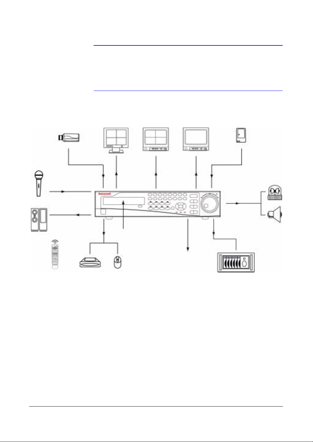
Figure 1-1 Typical DVR Installation
Up to 16 Cameras
Up to 4
Audio Inputs
Audio Output
IR Remote
Control
RGB Monitor
VGA Out
Internal DVD RW
Up to 3 USB Device
Mouse Support
Monitor
NTSC or PAL
Video Out
Digital Video Recorder
Up to 4 Monitors
Spot Outs
Network Connections
NTSC or PAL
Up to 16 Sensors
Flashing Light
Up to 16
Alarm Outputs
Siren
External SCSI
Hard Disk Drive
Document 800-04559 Rev D 23
11/09

HRXDS Series DVR User Guide
24

Installation
Installation
This chapter:
• Lists the package contents
• Shows the rear panel connectors
• Describes how to connect peripherals to the rear panel
2
Before You Begin
Please read this guide carefully before you install the HRXDS DVR. Keep this guide for
future reference.
Unpack Everything
Check that the items received match those listed on the order form and packing slip.
The HRXDS Series DVR packing box should include:
• Digital Video Recorder
•Power cord
• User Guide (this document)
• Multilingual User Guide (RASplus CD-ROM)
• RASplus User Guide
• Multilingual RASplus Software CD and User Guide (RASplus CD-ROM)
• DVRNS Server Software and User Guide (RASplus CD-ROM)
• Rack-mount Kit
• Assembly screws and guide rails for adding Hard Disk Drive
• Screws for attaching SCSI Connector
• Infrared Remote Control
If any parts are missing or damaged, contact the dealer you purchased the camera
from or call Honeywell Customer Service.
Document 800-04559 Rev D 25
11/09
HRXDS Series DVR User Guide
Required Installation Tools
No special tools are required to install the DVR. Refer to the installation manuals for the
other items that make up part of your system.
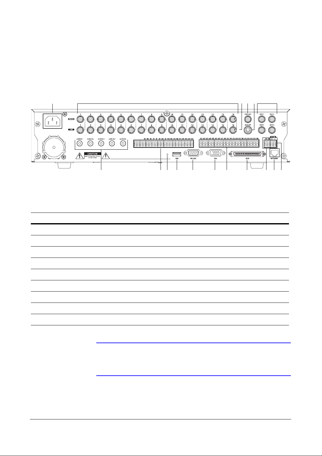
Figure 2-1 16-Channel DVR Rear Panel
17 1 2 3 4 5
NCCOMNO
Table 2-1 16-Channel DVR Real Panel Connector Descriptions
Location Description Location Description
678910111213141516
1 Video In 2 Video Loop Through
3Video Out 4SVHS Out
5 Spot Out 6 RS485 Port
7 Network Port 8 Alarm Reset In
9 SCSI Port 10 Alarm Out
11 VGA Port 12 RS232C Port
13 USB Port 14 Factory Reset Switch
15 Alarm In 16 Audio In/Out
17 Power Cord Connector
Note You can use your DVR with either NTSC or PAL equipment but
you cannot mix them. For example, you cannot use a PAL
camera and an NTSC monitor.
26

Installation
Connecting the Video Input
Figure 2-2 Video Input Connectors
Connect the coaxial cable from the video source to the BNC Video In connectors.
Connecting the Loop-Through Video
Figure 2-3 Video Loop-Through Connectors
If you would like to connect your video source to another device, you can use the Loop
BNC connectors.
Note The Loop BNC connectors are auto terminated. Do NOT connect
a cable to the Loop BNC unless it is connected to a terminated
device because it will cause poor quality video.
Document 800-04559 Rev D 27
11/09
Connecting the Monitor
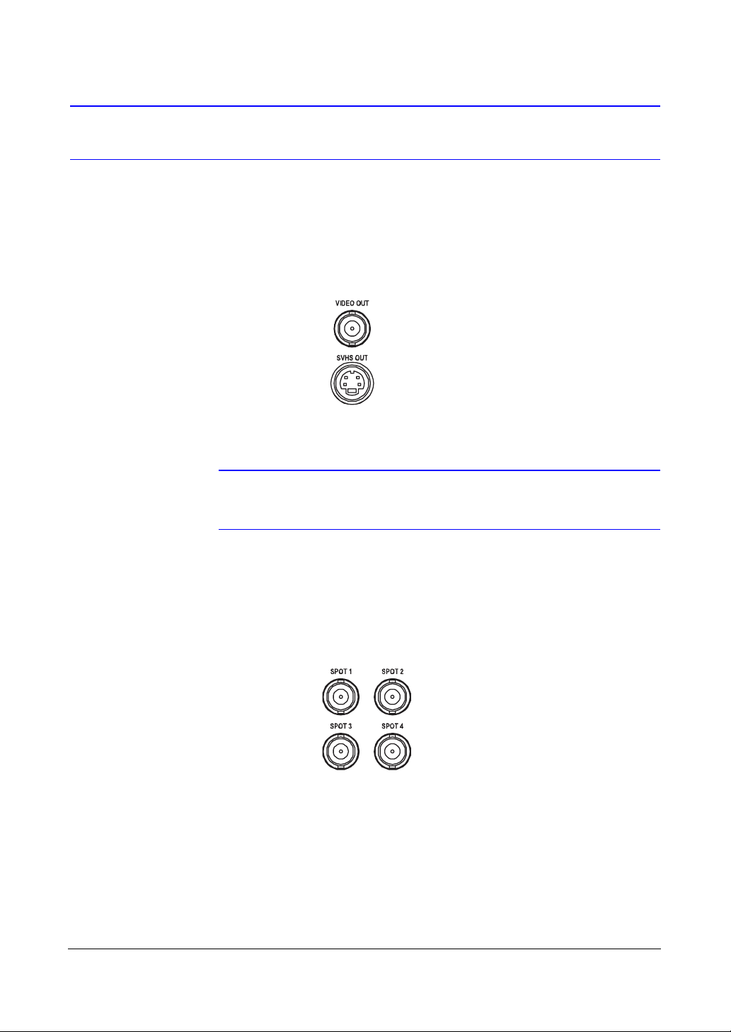
Video Out/SVHS Out
Figure 2-4 Video Out/SVHS Out Connectors
Connect the main monitor to either the Video Out or SVHS Out connector.
HRXDS Series DVR User Guide
Spot Out
Note If your main monitor has an SVHS input, Honeywell recommends
that you use it for better quality video display.
Figure 2-5 Spot Out Connectors
Connect up to four spot monitors to the SPOT 1, SPOT 2, SPOT 3 and SPOT 4
connectors as needed.
28

Installation
VGA Port
Figure 2-6 VGA Connector
A VGA connector is provided so that you can use a standard, multi-sync computer
monitor as your main monitor. Use the cable supplied with your monitor to connect it to
the DVR.
Note The Video Out (BNC), SVHS Out and VGA connectors may be
connected to individual monitors for simultaneous operation.
Connecting to the RS485 Port
Figure 2-7 RS485 Connector
The DVR can be controlled remotely by an external device or control system, such as a
control keyboard, using RS485 half-duplex serial communications signals. The RS485
connector can also be used to control PTZ (pan, tilt, zoom) cameras. Connect RX-/TXand RX+/ TX+ of the control system to the - and + (respectively) of the DVR. See
Chapter 3, Configuration and the PTZ camera or remote controller manufacture's
manual for configuring the RS485 connection.
Document 800-04559 Rev D 29
11/09

Connecting to the Network Port
Figure 2-8 Network Connector
The DVR can be networked using the 10/100Mb Ethernet connector. Connect a CAT5
cable with an RJ45 jack to the DVR connector. The DVR can be networked with a
computer for remote monitoring, searching, configuration and software upgrades. See
Chapter 3, Configuration for configuring the Ethernet connections.
Caution The network connector is not designed to be connected directly
with cable or wire intended for outdoor use.
HRXDS Series DVR User Guide
Connecting Alarms
Figure 2-9 Alarm Input Connectors
Note To make connections on the Alarm Connector Strip, press and
30
hold the button and insert the wire in the hole below the button.
After releasing the button, tug gently on the wire to make certain
it is connected. To disconnect a wire, press and hold the button
above the wire and pull out the wire.
 Loading...