

Page 1

HRTL-One
Digital Video Recorder
User Guide
Document 900.0259 – 10/04 – Rev 1.00
Page 2

HRTL-One Digital Video Recorder
User Guide
Page 3

Revisions
Issue Date Revisions
1.00 10/04 New document.
Page 4

HRTL-One Digital Video Recorder User Guide
Contents
About This Document . . . . . . . . . . . . . . . . . . . . . . . . . . . . . . . . . . . . . . . xi
Overview of Contents . . . . . . . . . . . . . . . . . . . . . . . . . . . . . . . . . . . . . . . . xi
Important Safeguards and Warnings . . . . . . . . . . . . . . . . . . . . . . . . . . . . . . . . . xii
Regulatory Compliance . . . . . . . . . . . . . . . . . . . . . . . . . . . . . . . . . . . . . . . xiii
Warranty and Service . . . . . . . . . . . . . . . . . . . . . . . . . . . . . . . . . . . . . . . xiii
Typographical Conventions. . . . . . . . . . . . . . . . . . . . . . . . . . . . . . . . . . . . . xiv
1 Overview . . . . . . . . . . . . . . . . . . . . . . . . . . . . . . . . . . . . . . . . . . . 1
Features . . . . . . . . . . . . . . . . . . . . . . . . . . . . . . . . . . . . . . . . . . . . . . . .1
2 Installation . . . . . . . . . . . . . . . . . . . . . . . . . . . . . . . . . . . . . . . . . . 3
Before You Begin . . . . . . . . . . . . . . . . . . . . . . . . . . . . . . . . . . . . . . . . . . . .3
Installing the Hard Drive . . . . . . . . . . . . . . . . . . . . . . . . . . . . . . . . . . . . . . . .4
Hard Drive Front Panel Functions. . . . . . . . . . . . . . . . . . . . . . . . . . . . . . . 7
Installing the HRTL-One in the Rack Mount . . . . . . . . . . . . . . . . . . . . . . . . . . . . . .8
Connecting the HRTL-One to Peripheral Equipment. . . . . . . . . . . . . . . . . . . . . . . . . . 8
Rear Panel Connections . . . . . . . . . . . . . . . . . . . . . . . . . . . . . . . . . . . 10
3 System Setup . . . . . . . . . . . . . . . . . . . . . . . . . . . . . . . . . . . . . . . . . 15
Recording Times . . . . . . . . . . . . . . . . . . . . . . . . . . . . . . . . . . . . . . . . . . . 16
Accessing the Menu Setup . . . . . . . . . . . . . . . . . . . . . . . . . . . . . . . . . . . . . . 18
Exiting the Menu Setup . . . . . . . . . . . . . . . . . . . . . . . . . . . . . . . . . . . . . . . . 19
Setting Overall System Configuration. . . . . . . . . . . . . . . . . . . . . . . . . . . . . . . . . 19
Setting the Internal Alarm Buzzer . . . . . . . . . . . . . . . . . . . . . . . . . . . . . . 20
Setting the Hard Drive Override . . . . . . . . . . . . . . . . . . . . . . . . . . . . . . 20
Message Latch Setup . . . . . . . . . . . . . . . . . . . . . . . . . . . . . . . . . . . . 21
Setting the Clock . . . . . . . . . . . . . . . . . . . . . . . . . . . . . . . . . . . . . . 21
Changing Your Password . . . . . . . . . . . . . . . . . . . . . . . . . . . . . . . . . . 22
Clearing the Data on the Hard Drive . . . . . . . . . . . . . . . . . . . . . . . . . . . . 23
Resetting to System Defaults . . . . . . . . . . . . . . . . . . . . . . . . . . . . . . . . 23
Timer Recording Setup . . . . . . . . . . . . . . . . . . . . . . . . . . . . . . . . . . . . . . . . 24
Recording Setup . . . . . . . . . . . . . . . . . . . . . . . . . . . . . . . . . . . . . . . . . . . 26
Alarm Mode Setup . . . . . . . . . . . . . . . . . . . . . . . . . . . . . . . . . . . . . . . . . . 27
Remote Protocol Setup. . . . . . . . . . . . . . . . . . . . . . . . . . . . . . . . . . . . . . . . 29
Event Reporting Setup . . . . . . . . . . . . . . . . . . . . . . . . . . . . . . . . . . . . . . . . 31
Rev 1.00 Document 900.0259
v
10/04
Page 5

Contents
4 Operation . . . . . . . . . . . . . . . . . . . . . . . . . . . . . . . . . . . . . . . . . . . 33
Front Panel LEDs . . . . . . . . . . . . . . . . . . . . . . . . . . . . . . . . . . . . . . . . . . . 34
Powering Up the HRTL-One . . . . . . . . . . . . . . . . . . . . . . . . . . . . . . . . . . . . . 34
Recording Video . . . . . . . . . . . . . . . . . . . . . . . . . . . . . . . . . . . . . . . . . . . 35
System Status Reporting. . . . . . . . . . . . . . . . . . . . . . . . . . . . . . . . . . . 35
Recording Video Triggered by an External Device . . . . . . . . . . . . . . . . . . . . . 36
Recording Timer Scheduled Video . . . . . . . . . . . . . . . . . . . . . . . . . . . . . 37
Recording Video Manually . . . . . . . . . . . . . . . . . . . . . . . . . . . . . . . . . . 37
Playing Back Video . . . . . . . . . . . . . . . . . . . . . . . . . . . . . . . . . . . . . . . . . . 38
Playing Back Single Images . . . . . . . . . . . . . . . . . . . . . . . . . . . . . . . . . . . . . . 39
Searching for Video Clips to Play Back . . . . . . . . . . . . . . . . . . . . . . . . . . . . . . . . 39
Video Loss . . . . . . . . . . . . . . . . . . . . . . . . . . . . . . . . . . . . . . . . . . . . . . 41
Key Lock . . . . . . . . . . . . . . . . . . . . . . . . . . . . . . . . . . . . . . . . . . . . . . . 42
Appendix A Solutions. . . . . . . . . . . . . . . . . . . . . . . . . . . . . . . . . . . . . . 43
Appendix B Compatible Hard Drives . . . . . . . . . . . . . . . . . . . . . . . . . . . . . 45
Appendix C Specifications . . . . . . . . . . . . . . . . . . . . . . . . . . . . . . . . . . .47
Appendix D Warranty . . . . . . . . . . . . . . . . . . . . . . . . . . . . . . . . . . . . .49
Index . . . . . . . . . . . . . . . . . . . . . . . . . . . . . . . . . . . . . . . . . . . . . . . . 1
Rev 1.00 Document 900.0259
vi
10/04
Page 6

HRTL-One Digital Video Recorder User Guide
Figures
Figure 2-1 Hard Drive Front Panel (Original Carrier) . . . . . . . . . . . . . . . . . . . . . . . . . . 7
Figure 2-2 Hard Drive Front Panel (New Carrier) . . . . . . . . . . . . . . . . . . . . . . . . . . .7
Figure 2-3 Rack Mount Installation. . . . . . . . . . . . . . . . . . . . . . . . . . . . . . . . . . . . 8
Figure 2-4 Single Camera Installation . . . . . . . . . . . . . . . . . . . . . . . . . . . . . . . . . .9
Figure 2-5 Multiple Cameras and Multiplexer Installation . . . . . . . . . . . . . . . . . . . . . . . . 9
Figure 2-6 Rear Panel Connections . . . . . . . . . . . . . . . . . . . . . . . . . . . . . . . . . . 10
Figure 2-7 9-Pin COM Port Pinout . . . . . . . . . . . . . . . . . . . . . . . . . . . . . . . . . . 11
Figure 2-8 25-Pin COM Port Pinout on External Device . . . . . . . . . . . . . . . . . . . . . . . 11
Figure 3-1 Front Panel Controls . . . . . . . . . . . . . . . . . . . . . . . . . . . . . . . . . . . . 15
Figure 3-2 Main Menu . . . . . . . . . . . . . . . . . . . . . . . . . . . . . . . . . . . . . . . . . 19
Figure 3-3 System Setup Menu. . . . . . . . . . . . . . . . . . . . . . . . . . . . . . . . . . . . . 20
Figure 3-4 Clear Hard Drive Screen . . . . . . . . . . . . . . . . . . . . . . . . . . . . . . . . . . 23
Figure 3-5 System Reset Screen . . . . . . . . . . . . . . . . . . . . . . . . . . . . . . . . . . . . 24
Figure 3-6 Timer Screen . . . . . . . . . . . . . . . . . . . . . . . . . . . . . . . . . . . . . . . . 25
Figure 3-7 Record Screen . . . . . . . . . . . . . . . . . . . . . . . . . . . . . . . . . . . . . . . 26
Figure 3-8 Alarm Screen . . . . . . . . . . . . . . . . . . . . . . . . . . . . . . . . . . . . . . . . 27
Figure 3-9 Remote Screen . . . . . . . . . . . . . . . . . . . . . . . . . . . . . . . . . . . . . . . 29
Figure 3-10 PC Keyboard / DVR Keypad . . . . . . . . . . . . . . . . . . . . . . . . . . . . . . . . 30
Figure 3-11 Event Screen . . . . . . . . . . . . . . . . . . . . . . . . . . . . . . . . . . . . . . . . 31
Figure 4-1 Front Panel Controls . . . . . . . . . . . . . . . . . . . . . . . . . . . . . . . . . . . . 33
Figure 4-2 Search Menu . . . . . . . . . . . . . . . . . . . . . . . . . . . . . . . . . . . . . . . . 39
Rev 1.00 Document 900.0259
vii
10/04
Page 7

HRTL-One Digital Video Recorder User Guide
Ta b l e s
Table 2-1 Hard Drive Front Panel Indicators . . . . . . . . . . . . . . . . . . . . . . . . . . . . . .7
Table 2-2 Rear Panel Connections to Peripheral Equipment. . . . . . . . . . . . . . . . . . . . . . 10
Table 2-3 9-Pin COM Port Pinouts . . . . . . . . . . . . . . . . . . . . . . . . . . . . . . . . . . 12
Table 3-1 Front Panel Controls . . . . . . . . . . . . . . . . . . . . . . . . . . . . . . . . . . . . 15
Table 3-2 NTSC Typical Recording Times (120 GB). . . . . . . . . . . . . . . . . . . . . . . . . . 17
Table 3-3 PAL Typical Recording Times (120 GB). . . . . . . . . . . . . . . . . . . . . . . . . . . 17
Table 3-4 NTSC Typical Recording Times (250 GB). . . . . . . . . . . . . . . . . . . . . . . . . . 17
Table 3-5 PAL Typical Recording Times (250 GB). . . . . . . . . . . . . . . . . . . . . . . . . . . 18
Table 3-6 Keypad Functions . . . . . . . . . . . . . . . . . . . . . . . . . . . . . . . . . . . . . . 30
Table 4-1 Play Speeds . . . . . . . . . . . . . . . . . . . . . . . . . . . . . . . . . . . . . . . . . 38
Rev 1.00 Document 900.0259
ix
10/04
Page 8

About This Document
This document introduces the HRTL-One Digital Video Recorder and describes how to
install the hard drive in the recorder, and then install the recorder and operate it.
The HRTL-One Digital Video Recorder is referred to as the HRTL-One throughout this
document.
HRTL-One Digital Video Recorder User Guide
Overview of Contents
This document contains the following chapters and appendixes:
• Chapter 1, Overview, introduces the HRTL-One and its features and functions.
• Chapter 2, Installation, shows the front and rear panel connections. It also describes
how to install the HRTL-One and connect it to peripheral equipment.
• Chapter 3, System Setup, describes how to set the overall system level
configuration.
• Chapter 4, Operation, shows how the HRTL-One front panel operates and
describes typical daily operating tasks.
• Appendix A, Solutions, lists typical technical issues and describes how to solve them.
• Appendix B, Compatible Hard Drives, lists compatible hard drive brands.
• Appendix C, Specifications, lists the specifications for the HRTL-One.
• Appendix D, Warranty, provides product warranty information.
Rev 1.00 900.0259
xi
10/04
Page 9

Important Safeguards and Warnings
Caution Please read all the safeguards and
warnings before operating the
HRTL-One.
Improper operation may cause
permanent, irreparable damage to the
HRTL-One digital video recorder.
Caution The installation of this equipment should be made only by qualified
technicians and should conform to all local codes.
Safety Cautions
Environment
• Please lift and place this equipment gently.
• Do not expose this equipment under straight sunlight.
• Do not use this equipment near or in contact with water.
Operation
• Operate this equipment only with the power source provided.
• Operate this equipment only from the type of power source indicated on the
manufacturer’s label.
• Do not switch the power on and off within a short period (within three seconds).
Proper Care and Maintenance
• Do not spill liquid of any kind on the equipment.
• Do not unplug the power connector before turning the power off.
Rev 1.00 900.0259
xii
10/04
Page 10
Service
Unauthorized repair or parts substitutions may result in fire, electric shock or other
hazards.
Regulatory Compliance
This device complies with part 15 of the FCC rules. Operation is subject to the following
two conditions: (1) This device may not cause harmful interference, and (2) this device
must accept any interference received, including interference that may cause undesired
operation.
HRTL-One Digital Video Recorder User Guide
RISK OF ELECTRIC
SHOCK
DO NOT OPEN
Œ
The Πmark on the product indicates that the system has been tested to and conforms
with the provisions noted within the EN 55024 Class A Electromagnetic Compatibility
Directive.
Warranty and Service
Subject to the terms and conditions listed on the Product Warranty (see Appendix D),
during the warranty period Honeywell will repair or replace, at its sole option, free of
charge, any defective products returned prepaid.
In the event you have a problem with any Honeywell product, please call Customer
Service for assistance or to request a Return Authorization (RA) number.
Call 1.800.796.CCTV.
Be sure to have the model number, serial number, and the nature of the problem
outlined for the technical service representative.
Prior authorization must be obtained for all returns, exchanges, or credits. Items
shipped to Honeywell without a clearly identified Return Authorization (RA) number
may be refused.
Rev 1.00 900.0259
xiii
10/04
Page 11

Typographical Conventions
This document uses the following typographical conventions:
Font What it represents Example
Lucida Values of editable fields that are mentioned in the
body text of the document for reference purposes,
but do not need to be entered as part of a
procedure
Text strings displayed on the screen The message
Lucida
Bold
Words or characters that you must type. The word
“enter” is used if you must type text and then press
the
Enter or Return key.
Values of editable fields that appear in tables (on first
mention)
Gill Sans
bold
Italic (any
font)
Menu titles and other items you select Select the Setup menu.
Buttons you click to perform actions Click Exit to close the program.
Placeholders: words that vary depending on the
situation
Cross-reference to external source Refer to the manual that came with your
The Time field can be set to
Hours:Minutes:Seconds
Password Updated
.
displays.
Enter the password:
1234
The Background Recording field can be
set to one of the following values:
Enabled
Disabled
Enter the basic parameters
hard drive.
Cross-reference within document See Overview.
Rev 1.00 900.0259
xiv
10/04
Page 12

Overview
1
The HRTL-One Digital Video Recorder converts analog NTSC or PAL video to digital
images and records them on a removable hard disk drive.
Digitally recorded video has several advantages over analog video recorded on tape,
including:
• There is no need to adjust tracking
• You can index digital video by time schedule or events
• You can instantly view video after selecting the time or event
• You can freeze frames, fast-forward, fast-reverse, slow-forward, and slow-reverse
without image streaking or tearing
• The HRTL-One Digital Video Recorder can be used as a replacement for a
time-lapse VCR in a security installation
Features
• Replaces a traditional timelapse VCR
• Compatible with most multiplexer and quad processors
• Compatible with NTSC and PAL
• Supports hard drive installation and upgrade in the field, up to 120 GB hard drive.
HRTL-One recorders with a serial number of 0405xxxxx and later support up to
250 GB hard drive
• Record speed options:
• NTSC: 1 image per second to 60 images per second
• PAL: 1 image per second to 50 images per second
• Offers a range of recording video compression settings to maximize usage of the
hard drive capacity
Recording video quality selection includes best, high, normal, and basic
• Quick search modes
Search video by time, event, or alarm list
• Variable viewing speeds
Rev 1.00 1 Document 900.0259
10/04
Page 13

Overview
Fast forward or reverse from 2X to 32X
Slow forward or reverse from 1/2X to 1/32X
• Time display format
• Password protection
• Alarm input enable record mode
One alarm input to activate recording
Auto detection for video loss
• One alarm input
One alarm output
• Time scheduled recording
• Power loss protection
Fault tolerance design provides quick, reliable recovery from power loss
• RS232C control port
The HRTL-One can be linked to external equipment through the RS-232C interface.
• The HRTL-One automatically stops recording when the hard drive disk is full or
continues recording when the overwrite feature is selected.
Rev 1.00 2 Document 900.0259
10/04
Page 14

Installation
This chapter describes how to:
• Install a hard drive in the HRTL-One.
• Install the HRTL-One in a 19 inch (482.6 mm) rack.
• Connect the HRTL-One to peripheral equipment. Depending on your
Before You Begin
Check that the items received match those listed on the packing slip. The HRTL-One
packing box should include, in addition to this User Guide:
2
requirements, you can connect the HRTL-One to a variety of equipment, including
camera(s), a monitor, multiplexer, alarm input or remote PC or laptop.
• One single channel HRTL-One Digital Video Recorder
• One hard drive cartridge and a key for the cartridge (key located inside cartridge)
• One power converter and power cord
• One DB-15 plug
• One rack mounting kit
• 80 GB Hard Drive (included with HRTL-One-80 DVR, not included with
HRTL-One DVR)
If any parts are missing or damaged, please contact the dealer you purchased the
HRTL-One from, or call Honeywell Customer Service. See Warranty and Service, page
xiii.
Rev 1.00 3 Document 900.0259
10/04
Page 15
Installation
Installing the Hard Drive
Caution The HRTL-One must be powered off before installing a new hard disk drive
or removing an existing hard disk drive.
Do not remove the hard drive until after the HRTL-One has been powered
down for at least 60 seconds. This will protect the hard drive from possible
damage.
The hard drive must be installed before the HRTL-One can record video. For a list of
compatible hard drives, see Appendix B.
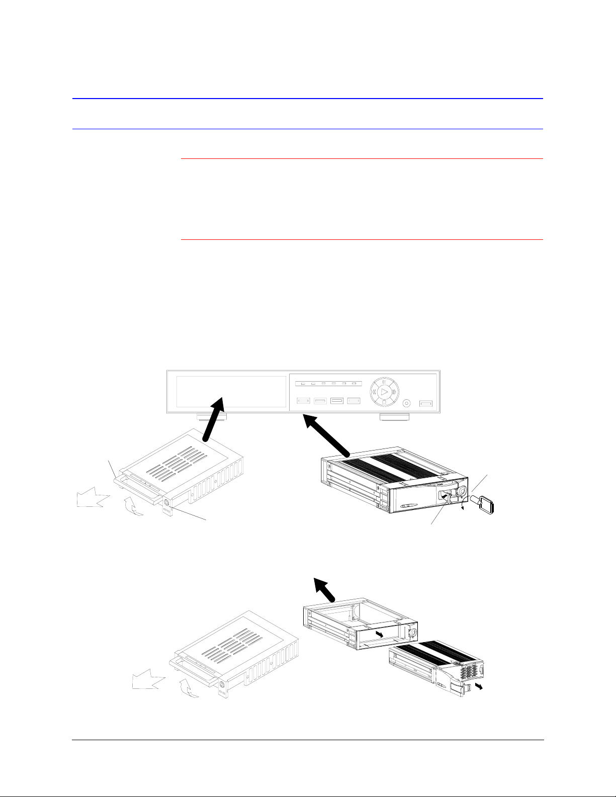
To install the hard drive:
1. Pull the active-handle outwards, then insert the miniature key (supplied in the hard
drive cartridge) into the key hole, turning the key counter-clockwise to the “power
off” (unlocked) position.
Active-handle
2. Pull the handle towards you to remove the carrier body away from the HRTL-One
New HD Carrier
Hard drive cartridge
New HD Carrier
Keyhole
chassis.
HDD Full
HDD
ALARM TIMER PLAY
MENU ENTER SEARCH SLOW
HRTL-One chassis
PAUSE
REC
/ Up
REW
Left
FF
Right
REC
STOP
/ Down
POWER
Original HD Carrier
Key
Active-handle
Original HD Carrier
Cartridge frame
Carrier body
Rev 1.00 4 Document 900.0259
10/04
Page 16
HRTL-One Digital Video Recorder User Guide
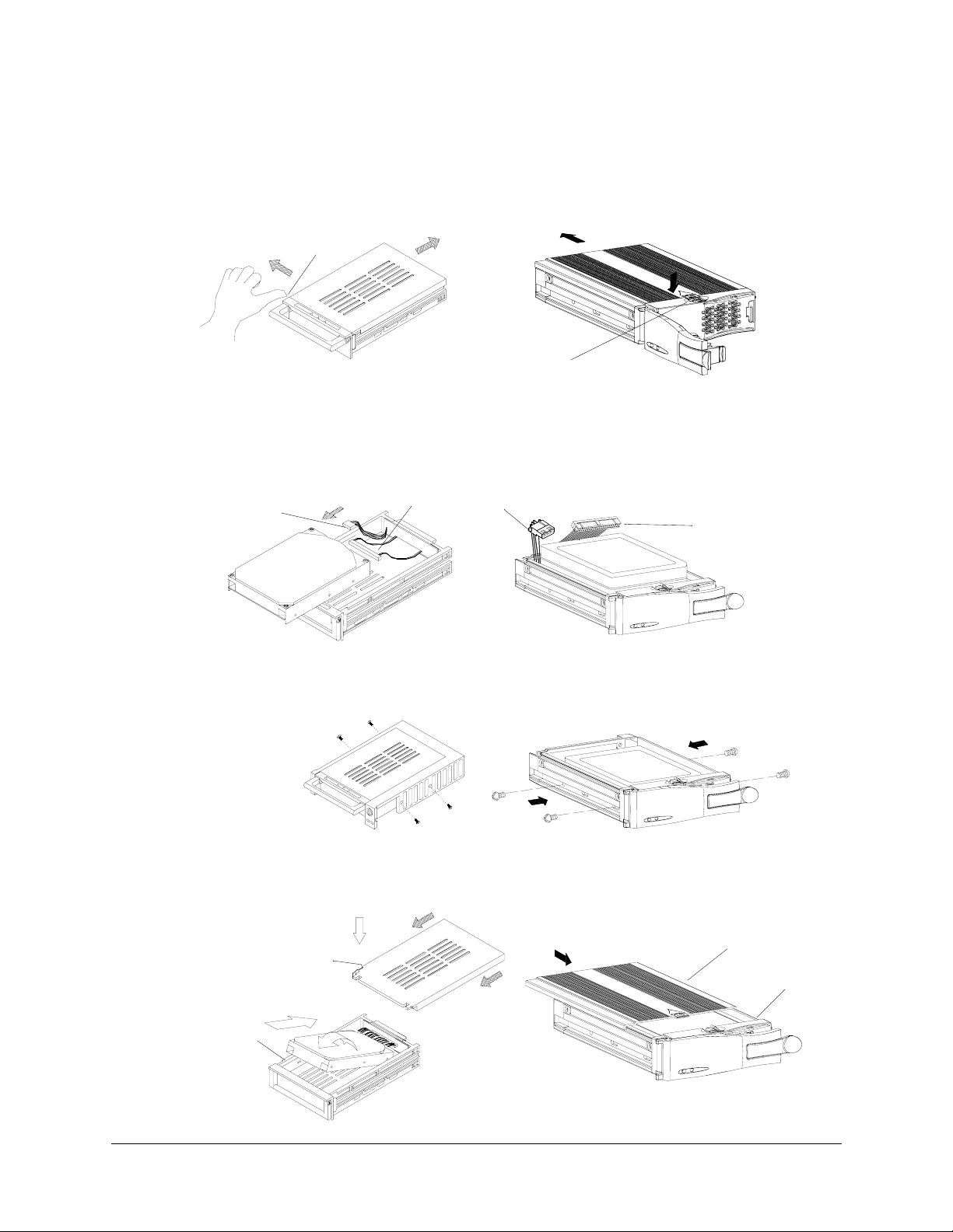
3. Push the black release latch on top of the carrier body (original carrier) or push the
side release latch with the word OPEN printed beside it (new carrier) to slide the
top cover backwards until it is completely removed.
New HD Carrier
Release latch
4. Ensure that the hard drive is configured as Master. Refer to the documentation
5. Plug the PC power cable and IDE ribbon cable into the hard drive cartridge.
New HD Carrier
PC power cable
6. Position the hard drive cartridge into the carrier body. Secure the hard drive using
Original HD Carrier
Release latch
supplied with the hard drive for the jumper settings.
Original HD Carrier
IDE ribbon cable
the four #6-32 screws supplied.
PC power cable
IDE ribbon cable
New HD Carrier
Original HD Carrier
7. Slide the top cover back on the carrier body by sliding it forward. The silver tab
(original carrier) or the side latch (new carrier) clicks over the black release latch to
secure the cover in place.
New HD Carrier
Top cover
Carrier body
Original HD Carrier
Top cover
Carrier body
Rev 1.00 5 Document 900.0259
10/04
Page 17
Installation
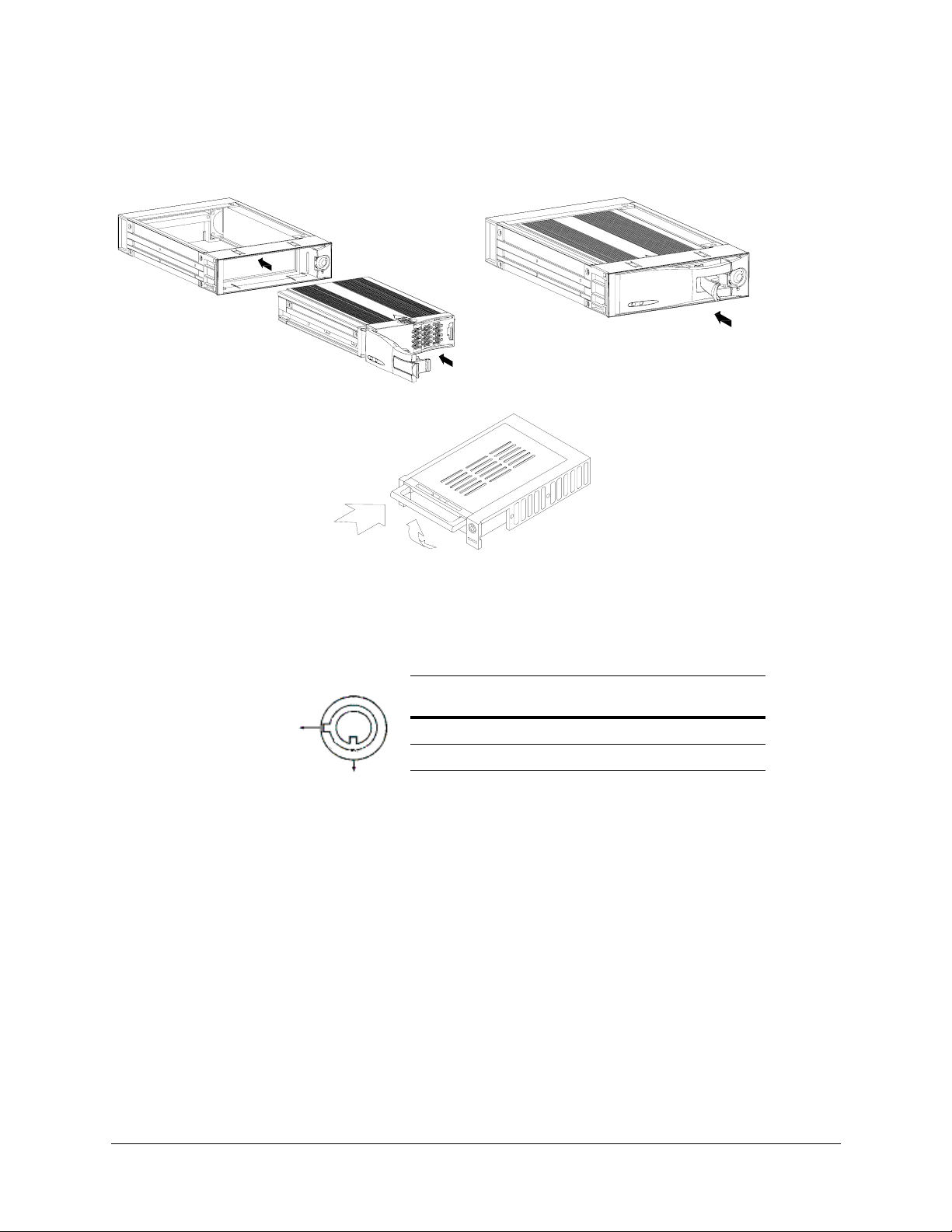
8. Slide the carrier body back into the cartridge frame until it is fully inserted.
Original HD Carrier
New HD Carrier
9. Push the handle towards the key lock (original carrier). Push the handle down to
secure the carrier in place (new carrier).
10. To ensure that the hard drive functions properly, turn the key lock clockwise to the
A position before powering the hard drive on.
Status
segment
A
A ON Locked (hard drive cannot be removed)
B OFF Unlocked (removable)
Power
status
Security status
B
Rev 1.00 6 Document 900.0259
10/04
Page 18
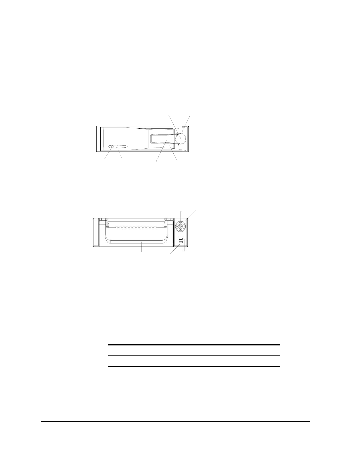
Hard Drive Front Panel Functions
Figure 2-1 shows the front panel of the hard drive and lists the functions of the various
components.
Figure 2-1 Hard Drive Front Panel (Original Carrier)
HRTL-One Digital Video Recorder User Guide
1
2
6
3
4
Legend
5
1. Hard drive access indicator
2. Power indicator
3. Active-handle
4. Handle
5. Cartridge frame
6. Key lock
Figure 2-2 Hard Drive Front Panel (New Carrier)
Legend
5
1. Hard drive access indicator
2. Power indicator
3. Active-handle
4. Handle
5. Cartridge frame
6. Key lock
34
6
2
1
Indicators
When the hard drive is powered up, the indicators display as follows:
Table 2-1 Hard Drive Front Panel Indicators
Indicator Color
Hard drive access indicator Amber
Power indicator Green
Rev 1.00 7 Document 900.0259
10/04
Page 19
Installation
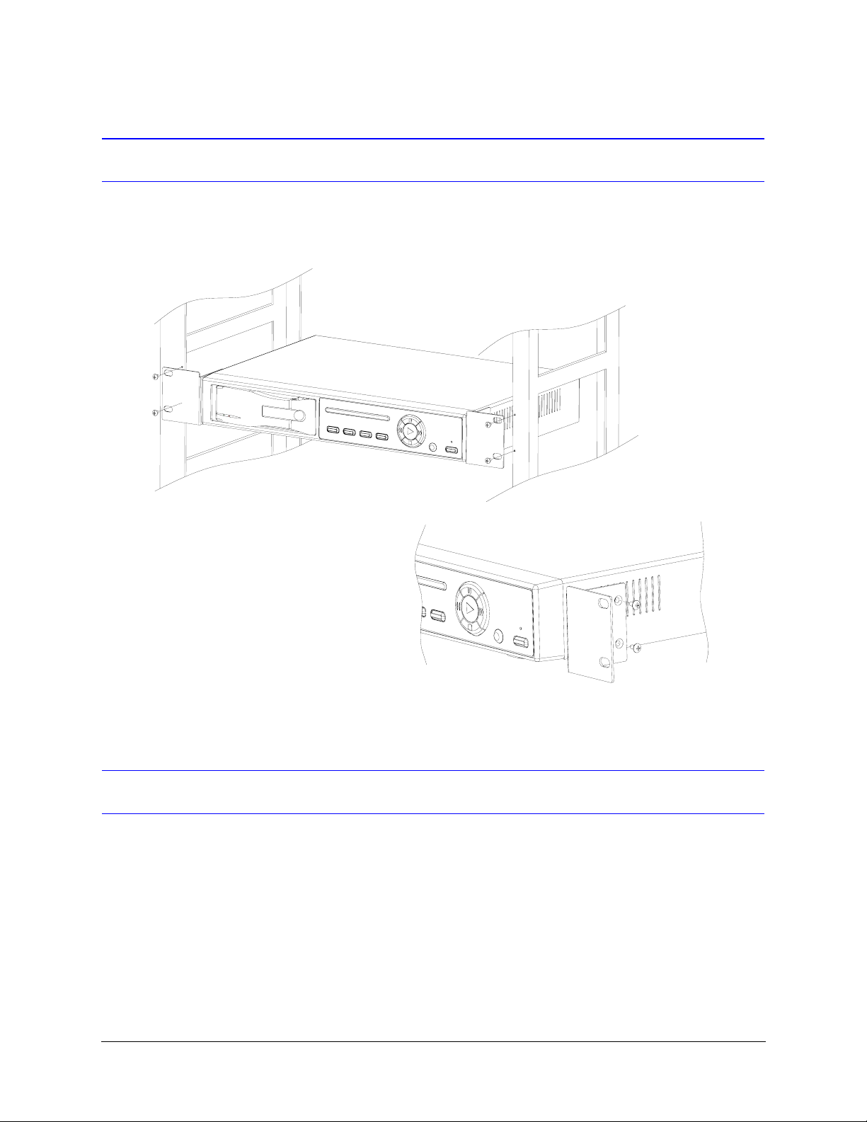
Installing the HRTL-One in the Rack Mount
Follow Figure 2-3 to mount the HRTL-One in the rack mount.
Figure 2-3 Rack Mount Installation
Front view
Side view
Connecting the HRTL-One to Peripheral Equipment
The HRTL-One is designed to work with a variety of other equipment, including:
• Video camera(s). You can connect:
• A single video camera
• An external multiplexer that is connected to up to 16 cameras.
• Monitor
• Alarm sensor or Personal Computer (PC)
Figure 2-4 and Figure 2-5 show typical single camera and multiplexer installations.
Rev 1.00 8 Document 900.0259
10/04
Page 20

HRTL-One Digital Video Recorder User Guide
Figure 2-4 Single Camera Installation
DVR
Figure 2-5 Multiple Cameras and Multiplexer Installation
Switch out
Rev 1.00 9 Document 900.0259
10/04
Page 21

Installation
Rear Panel Connections
Figure 2-6 shows the rear panel connections and Table 2-2 describes the connections.
Figure 2-6 Rear Panel Connections
VIDEO IN
POWER
VIDEO OUT
ALARM
Table 2-2 Rear Panel Connections to Peripheral Equipment
Connection Description
1. Video In Connect to video source (for example, a quad, multiplexer, or
camera).
2. Video Out Connect to a monitor if there is no quad or multiplexer in your
system (see Figure 2-4).
Connect to the video input of a quad or multiplexer, as shown
in Figure 2-5.
3. External
I/O
• RS-232 / RS-485 front panel command line interface
Controlled remotely by an external device or control
system (see Figure 2-4).
• Multiplexer synchronization
• Disk full indication
• Record enable/disable
• Video loss indication
• Alarm input/output
4. Power Connect to power cable.
Rev 1.00 10 Document 900.0259
10/04
Page 22

HRTL-One Digital Video Recorder User Guide
Alarm I/O Port
Figure 2-7 shows the 15-pin COM port pinouts on the rear panel of the HRTL-One for a
typical HRTL-One PC to DVR interface (RS-232 communication via DB9 connector).
Figure 2-8 shows the 15-pin COM port pinouts on the rear panel of the HRTL-One and
typical interface for RS-232 communication via DB25 connector. Table 2-3 describes the
9-pin pinouts.
Figure 2-7 9-Pin COM Port Pinout
Figure 2-8 25-Pin COM Port Pinout on External Device
Rev 1.00 11 Document 900.0259
10/04
Page 23

Installation
Table 2-3 9-Pin COM Port Pinouts
Pin Type Function
1 RS232-TX:
RS232
2 RS232-RX:
RS232
3 Video loss If video loss occurs, the system sends a signal to trigger another accessory. This pin
4 Switch out Connect to the VCR trigger recording terminal of the multiplexer to synchronize
5 Error out This pin becomes Low when hard drive errors occur and remains High under normal
6 Rec start This pin can accept the external trigger signal to activate record mode from an
7 External alarm NCUnder normal operation, COM (pin 15) connects with NC and disconnects with NO
The HRTL-One can be controlled remotely by an external device or control system
(for example, a control keyboard), using RS-232 serial communications signals. See
RS-232/RS-485 Remote Protocol, page 30.
The HRTL-One can be controlled remotely by an external device or control system
(for example, a control keyboard), using RS-232 serial communications signal.
output becomes Low when video loss occurs, and remains High under normal
operation.
recording signals. The default mode is falling (negative) edge.
operation.
external device. Options are:
Low: (default) When the external signal turns to Low it triggers the HRTL-One record
mode.
High: When the external signal turns back to High the HRTL-One stops recording.
(pin 8).
When an alarm is triggered, COM disconnects with NC and connects with NO.
8 External alarm NOUnder normal operation, COM (pin 15) connects with NC and disconnects with NO
(pin 7).
When an alarm is triggered, COM disconnects with NC and connects with NO.
9GND Ground
10 RS-485-B The HRTL-One can be controlled remotely by an external device or control system
(for example, a control keyboard) using RS-485 serial communication signals.
11 RS-485-A The HRTL-One can be controlled remotely by an external device or control system
(for example, a control keyboard) using RS-485 serial communication signals.
12 Disk full Under normal operation the state remains High.
When the disk is full, the HRTL-One sends a Low state.
Example:
When the hard drive is full and you have installed another HRTL-One recorder, a
signal can be sent to the next HRTL-One to activate recording.
Rev 1.00 12 Document 900.0259
10/04
Page 24

HRTL-One Digital Video Recorder User Guide
Table 2-3 9-Pin COM Port Pinouts
Pin Type Function
13 Alarm reset When the wire from the Alarm reset (pin 13) is connected to Ground (pin 9)
connector, it can disable the HRTL-One alarm notification (buzzer and flashing LED).
An external signal to Alarm reset (pin 13) can be used to reset both the Alarm output
signal and the internal buzzer on the HRTL-One. When an alarm has been triggered,
the signal becomes Low and all alarm activities are stopped.
Under normal operation the signal remains High.
14 Alarm input When the wire from Alarm input (pin 14) is connected to ground (pin 9) connector,
the HRTL-One starts recording and the buzzer will be on.
Under normal operation, the signal remains High.
15 COM Under normal operation, COM connects with NC (pin 7) and disconnects with NO
(pin 8).
When an alarm is triggered, COM disconnects with NC and connects with NO.
Rev 1.00 13 Document 900.0259
10/04
Page 25

System Setup
This chapter describes the front panel controls and how to use them to configure your
system and perform daily routine operations.
Figure 3-1 Front Panel Controls
3
HDD FullHDD ALARM PLAY REC
TIMER
MENU ENTER SLOWSEARCH
/ Up
Left
Right
REC
POWER
/ Down
Table 3-1 Front Panel Controls
Control Function
1. Hard
drive
The HRTL-One comes with a removable hard drive disk tray. Before powering up the HRTL-One
you must first install the hard drive and turn the key lock to the A position. See Installing the Hard
Drive, page 4.
2. MENU Press to enter Program mode and enter the Administrator password (default is 0000) to access the
Main Menu.
Press to navigate up the menu structure:
• Through the fields on the menus
• From the sub-menus back to the Main Menu
3. ENTER Press to accept changes that you make in Program mode.
4. SEARCH Press to search for previously recorded video.
5. SLOW Press to slow down the speed of Play mode.
6. STOP Press to stop recording or playing.
Rev 1.00 15 Document 900.0259
10/04
Page 26

System Setup
Table 3-1 Front Panel Controls
Control Function (cont’d)
7. REC Press to start recording.
8. POWER Press to power up the HRTL-One. Press again to power off the HRTL-One.
9. REW
(Left)
10. FF
(Right)
11. PAUSE Press to pause the video at the currently displayed image.
12. PLAY Press to play recorded video.
13. LEDs Under the following conditions, the red light is ON:
Press once to play video backward at high speed. Press again to adjust the speed (1, 2, 4, 8, 16, 32
times, depending on the number of times you press this button).
Press once to play video forward at high speed. Press again to adjust the speed (1, 2, 4, 8, 16, 32
times, depending on the number of times you press this button).
• HDD = The hard drive is activated.
• HDD FULL = The hard drive is full.
• ALARM = When alarm enable is set to Yes and an alarm is triggered, the LED flashes red.
• TIMER = When the recording timer is set for operation.
• PLAY = The HRTL-One is in Play mode.
• REC = The HRTL-One is in Record mode.
Recording Times
The record time depends on the record speed and record quality settings (see Recording
Setup, page 26). Table 3-2 provides typical NTSC recording times and Table 3-3 provides
typical PAL recording times for a 120 GB hard drive. Table 3-4 provides typical NTSC
recording times and Table 3-5 provides typical PAL recording times for a 250 GB hard
drive.
Rev 1.00 16 Document 900.0259
10/04
Page 27

HRTL-One Digital Video Recorder User Guide
Note Table 3-2 and Table 3-3 are based on a 120 GB hard drive, Table 3-4
and Table 3-5 are based on a 250 GB hard drive.
The data in these tables was obtained by recording a normal TV
program and is provided for reference only.
Table 3-2 NTSC Typical Recording Times (120 GB)
Record
quality
Best 12 hr 24 hr 48 hr 90 hr 180 hr 360 hr 720 hr
High 15 hr 30 hr 60 hr 112.5 hr 225 hr 450 hr 900 hr
Normal 24 hr 48 hr 96 hr 180 hr 360 hr 720 hr 1440 hr
Basic 40 hr 80 hr 160 hr 300 hr 600 hr 1200 hr 2400 hr
Table 3-3 PAL Typical Recording Times (120 GB)
Record
quality
Best 12 hr 24 hr 50 hr 101 hr 203 hr 304 hr 608 hr
High 15 hr 30 hr 63 hr 127 hr 253 hr 380 hr 760 hr
Normal 24 hr 49 hr 101 hr 203 hr 405 hr 608 hr 1220 hr
Basic 41 hr 81 hr 168 hr 338 hr 675 hr 1013 hr 2025 hr
Table 3-4 NTSC Typical Recording Times (250 GB)
6030158421
5025126321
IPS
IPS
Record
quality
Best 25 hr 50 hr 100 hr 187.5 hr 375 hr 750 hr 1500 hr
High 31.3 hr 62.5 hr 125 hr 234.4 hr 468.8 hr 937.5 hr 1875 hr
Normal 50 hr 100 hr 200 hr 375 hr 750 hr 1500 hr 3000 hr
Basic 83.3 hr 166.7 hr 333.3 hr 625 hr 1250 hr 2500 hr 5000 hr
Rev 1.00 17 Document 900.0259
60 30 15 8 4 2 1
IPS
10/04
Page 28

System Setup
Table 3-5 PAL Typical Recording Times (250 GB)
Record
quality
Best 25 hr 50 hr 104.2 hr 210.4 hr 422.9 hr 633.3 hr 1266.7 hr
High 31.3 hr 62.5 hr 131.3 hr 264.6 hr 527.1 hr 791.7 hr 1583.3 hr
Normal 50 hr 102.1 hr 210.4 hr 422.9 hr 843.8 hr 1266.7 hr 2541.7 hr
Basic 85.4 hr 168.8 hr 350 hr 704.2 hr 1406.3 hr 2110.4 hr 4218.8 hr
50 25 12 6 3 2 1
Accessing the Menu Setup
After you have powered on the HRTL-One, access the menu setup as follows:
1. Press MENU on the front panel of the HRTL-One.
2. You are prompted to enter a password. Press W or X to move to the next digit and
S or T to select the number. Press Enter to confirm the password.
IPS
Note The default password is 0000.
Password: 0000
3. The Main menu displays, indicating you have entered the correct password.
Rev 1.00 18 Document 900.0259
10/04
Page 29

Figure 3-2 Main Menu
HRTL-One Digital Video Recorder User Guide
(Menu)
Timer
J
Record
Alarm
Remote
System
Event
4. Press S or T to navigate through the menu items. For example, to select the
system setup, move to System, then press Enter.
Exiting the Menu Setup
To exit menu setup:
Legend
Timer = Record scheduling
Record = Record mode setup
Alarm = Alarm mode setup
Remote = Remote control setup
System = System setup
Event = Event list
• From the Main menu, press the Menu button.
• From the submenus, press the Menu button to navigate back to the Main menu,
then press Menu again to exit menu setup.
The HRTL-One automatically exits menu setup after 60 seconds of inactivity.
Setting Overall System Configuration
Use the System screen to set system-level configurations, including:
• Set the internal alarm buzzer
• Set the system clock
• Change password
• Clear the data on the hard drive
• Reset the system to the factory default settings
From the Main Menu, select System, then press Enter. Figure 3-3 displays.
Rev 1.00 19 Document 900.0259
10/04
Page 30

System Setup
Figure 3-3 System Setup Menu
(System)
Buzzer: On
J
HDD Overwrite: No
Message Latch: No
Date Display: Y-M-D
Date: 2002-JUL-14(SUN)
Time: 22:38:29
New Password: xxxx
Clear HDD: No
System Reset: No
Setting the Internal Alarm Buzzer
To enable or disable the internal alarm buzzer:
1. On the System screen (Main Menu ➤ System), press S or T to select Buzzer,
then press Enter.
2. Press S or T to enable or disable the internal alarm buzzer. Options are:
ON = Buzzer is on. When the HRTL-One detects an alarm trigger (for example,
when the hard drive is full) a buzzer sounds to alert the user.
OFF = Buzzer is off.
3. Press Menu to confirm your change.
4. Press S or T to move to another field on the System screen or press Menu to exit
this screen and confirm the current operation.
5. If you have completed all your system configuration changes, press Menu again to
exit and close menu setup.
Setting the Hard Drive Override
When the hard drive is full you can either:
• Have the HRTL-One overwrite the hard drive, OR
• Have the HRTL-One stop recording
1. On the System screen (Main Menu ➤ System), press S or T to select HDD
Overwrite, then press Enter.
2. Press S or T to enable or disable the hard drive overwrite option. Options are:
YES = The HRTL-One overwrites the data on the hard drive when the drive is full.
NO = Turns auto reverse off. The HRTL-One stops recording when the drive is full.
3. Press Menu to confirm your change.
Rev 1.00 20 Document 900.0259
10/04
Page 31

4. Press S or T to move to another field on the System screen or press Menu to exit
this screen and confirm the current operation.
5. If you have completed all your system configuration changes, press Menu again to
exit and close menu setup.
Message Latch Setup
HRTL-One Digital Video Recorder User Guide
This feature is used to select whether the
seconds or remain on the screen.
(System)
Buzzer: On
HDD Overwrite: No
Message Latch: No
J
Date Display: Y-M-D
Date: 2002-JUL-14(SUN)
Time: 22:38:29
New Password: xxxx
Clear HDD: No
System Reset: No
No
HDD Full
is the default setting.
When you set up the message latch to be On (
Overwrite
is not enabled, the message
HDD Full
you disable the message latch.
When you set up the message latch to be Off (
only 10 seconds.
message will disappear after 10
Yes
), once the hard drive fills up, and
will be displayed on the screen until
No
), the
HDD Full
message will appear for
HDD
Setting the Clock
You can set the system date and time and how the date displays on the Display Date
screen.
On-screen Display
1. On the System screen (Main Menu ➤ System), press S or T to select Date
Display, then press Enter.
2. Press S or T to choose a display format. Options are:
Y-M-D = Year - Month - Day
M-D-Y = Month - Day - Year
D-M-Y = Day-Month-Year
Rev 1.00 21 Document 900.0259
10/04
Page 32

System Setup
Off = The date and time will not show on the screen.
3. Press Menu to confirm your change.
4. Press S or T to move to another field on the System screen or press Menu to exit
this screen and confirm the current operation.
System Date
1. On the System screen (Main Menu ➤ System), press S or T to select System
Date, then press Enter.
2. Press S or T to choose a number, then press W or X to move to the next digit:
2002-JUL-14(SUN), YY-MM-DD(Day)
3. Press Menu to confirm your change.
4. Press S or T to move to another field on the System screen or press Menu to exit
this screen and confirm the current operation.
System Time
1. On the System screen (Main Menu ➤ System), press S or T to select Time,
then press Enter.
2. Press S or T to choose a number, then press W or X to move to the next digit:
Time: 22:38:29 HH:MM:SS; Hour, Minute, Second
3. Press Menu to confirm your change.
4. Press S or T to move to another field on the System screen or press Menu to exit
this screen and confirm the current operation.
5. If you have completed all your system configuration changes, press Menu again to
exit and close menu setup.
Changing Your Password
To change your password:
1. On the System screen (Main Menu ➤ System), press S or T to select New
Password, then press Enter.
2. Press S or T to choose a number, then press W or X to move to the next digit:
xxxx
3. Press Menu to confirm your change.
4. Press S or T to move to another field on the System screen or press Menu to exit
this screen and confirm the current operation.
Rev 1.00 22 Document 900.0259
10/04
Page 33

5. If you have completed all your system configuration changes, press Menu again to
exit and close menu setup.
Clearing the Data on the Hard Drive
Caution Clearing the data on the hard drive results in permanent, irreversible loss of
all video and other information currently stored on the hard drive.
To remove all the data from the hard drive:
1. On the System screen (Main Menu ➤ System), press S or T to select Clear
HDD, then press Enter.
2. Press S or T to choose:
Yes = Clear the hard drive.
HRTL-One Digital Video Recorder User Guide
No = Do not clear the hard drive at this time.
When you select Yes, the following screen displays:
Figure 3-4 Clear Hard Drive Screen
All Data in HDD
Will be Cleared
Are You Sure?
(I : No J : Yes)
3. Press X to clear the hard drive or W to abort the clear process.
4. Press Menu to exit this screen and confirm the current operation.
5. If you have completed all your system configuration changes, press Menu again to
exit and close menu setup.
Resetting to System Defaults
To reset the system to the factory default settings:
1. On the System screen (Main Menu ➤ System), press S or T to select System
Reset, then press Enter.
Rev 1.00 23 Document 900.0259
10/04
Page 34

System Setup
2. Press S or T to choose:
Yes = Confirm the system reset and load the default settings.
No = Do not reset the system at this time.
When you select Yes, the following screen displays:
Figure 3-5 System Reset Screen
(System)
Buzzer: On
HDD Overwrite: No
Message Latch: No
Date Display: Y-M-D
Date: 2002-JUL-14(SUN)
Time: 22:38:29
New Password: xxxx
Clear HDD: No
System Reset: No
J
3. Press Menu to exit this screen and confirm the current operation.
4. If you have completed all your system configuration changes, press Menu again to
exit and close menu setup.
Note Resetting the system will not change the date, time, and password settings.
Timer Recording Setup
Use the Timer screen to set timed daily recording and holiday scheduling.
1. On the Main Menu screen, press S or T to select Timer, then press Enter. The
following screen appears:
Rev 1.00 24 Document 900.0259
10/04
Page 35

Figure 3-6 Timer Screen
HRTL-One Digital Video Recorder User Guide
(Timer)
J
(Menu)
Timer
Record
Alarm
Remote
System
Event
Day Start End IPS
----- --:-- --:-- ---
----- --:-- --:-- ---
----- --:-- --:-- ---
----- --:-- --:-- ---
----- --:-- --:-- ---
----- --:-- --:-- ---
----- --:-- --:-- --Timer Enable No
2. Press Enter on the line you wish to edit.
3. Press S or T to choose the day. Options are:
Daily = Sets the same start and end recording times for each day of the week.
SUN = Sunday
MON = Monday
TUE = Tuesday
WED = Wednesday
THU = Thursday
FRI = Friday
SAT = Saturday
MO~FR = Monday to Friday
SA~SU = Saturday and Sunday
JAN-01 = Special date (can be set to any day of the year)
4. Press W or X to move to the Start record time, where 00:00 is HH:MM.
Press S or T to change the Start record time numerical digit.
5. Press W or X to move to the End record time, where 00:00 is HH:MM.
Press S or T to change the End record time numerical digit.
6. Press W or X to move to the IPS (images per second) field.
Press S or T to change the IPS selection.
NTSC = 1, 2, 4, 8, 15, 30, 60
OR
PAL = 1, 2, 3, 6, 12, 25, 50
OR
OFF = Not activated
7. Press Menu to confirm your change.
8. Press S or T to select Timer Enable, then press Enter. Options are:
Rev 1.00 25 Document 900.0259
10/04
Page 36

System Setup
9. Press Menu to confirm your change.
10. If you have completed all your system configuration changes, press Menu again to
Recording Setup
Yes = Timed recording is activated.
No = Timed recording is not activated.
exit and close menu setup.
Note Do not overlap timers. If timers overlap, the HRTL-One stops recording at
the end of the first timer interval.
Use the Record screen to set:
• Image per second (IPS) ratio
•Record quality
•Recording format
1. On the Main Menu screen, press S or T to select Record, then press Enter. The
following screen appears:
Figure 3-7 Record Screen
(Record)
J
(Menu)
Timer
Record
Alarm
Remote
System
Event
Record IPS: 60
J
Record Quality: Normal
Record Mode: Frame
2. Press S or T to select the Record IPS (images per second) field, then press
Enter.
Press S or T to choose from the following options:
NTSC = 1, 2, 4, 8, 15, 30, 60
OR
PAL = 1, 2, 3, 6, 12, 25, 50
Rev 1.00 26 Document 900.0259
10/04
Page 37

HRTL-One Digital Video Recorder User Guide
Press Menu to confirm your changes.
3. Press S or T to select the Record Quality field, then press Enter.
Press S or T to choose from the following options:
See Table 3-2 (NTSC) or Table 3-3 (PAL) as a guide to determine the record
duration vs. the quality selected.
Press Menu to confirm your changes.
4. Press S or T to select the Record Mode field, then press Enter.
Press S or T to choose from the following options:
Fields, Frames
Press Menu to confirm your changes.
5. Press Menu to exit this screen and confirm the current operations.
6. If you have completed all your system configuration changes, press Menu again to
exit and close menu setup.
Alarm Mode Setup
Use the Alarm screen to set how the system responds to an alarm event (for example,
video loss, power failure, full hard drive).
1. On the Main Menu screen, press S or T to select Alarm, then press Enter. The
following screen appears:
Figure 3-8 Alarm Screen
(Menu)
Timer
Record
Alarm
J
Remote
System
Event
2. Press S or T to select the Alarm Enable field, then press Enter.
Press S or T to choose from the following options:
(Alarm)
Alarm Enable: Yes
J
Alarm Duration: 1 MIN
Record IPS: 60
Quality: High
Record Mode: Frame
Yes = Turns on the alarm and activates a steady alarm LED on the front panel.
When the HRTL-One detects an alarm condition, the appropriate LED on the
front panel flashes to alert the user.
Rev 1.00 27 Document 900.0259
10/04
Page 38

System Setup
If the buzzer is enabled (see Setting the Internal Alarm Buzzer, page 20), the
HRTL-One also buzzes to alert the user.
No = The alarm is not turned on. The system will not respond when it detects
an alarm condition.
Press Menu to confirm your changes.
3. Press S or T to select the Alarm Duration field, then press Enter.
Press S or T to choose from the following options:
10 Sec, 15 Sec, 20 Sec, 30 Sec, 1 Min, 2 Min, 3 Min, 5 Min, 10 Min, 15
Min, 30 Min,
Always = Until the alarm condition is reset (pin 13 of the COM port)
Press Menu to confirm your changes.
4. Press S or T to select the Record IPS (images per second) field, then press
Enter.
Press S or T to choose from the following options:
NTSC = 1, 2, 4, 8, 15, 30, 60
OR
PAL = 1, 2, 3, 6, 12, 25, 50
Press Menu to confirm your changes.
5. Press S or T to select the Record Quality field, then press Enter.
Press S or T to choose from the following options:
Best, High, Normal, Basic
Press Menu to confirm your changes.
6. Press S or T to select the Record Mode field, then press Enter.
Press S or T to choose from the following options:
Fields, Frames
Press Menu to confirm your changes.
7. Press Menu to exit this screen and confirm the current operations.
8. If you have completed all your system configuration changes, press Menu again to
exit and close menu setup.
Rev 1.00 28 Document 900.0259
10/04
Page 39

Remote Protocol Setup
You can control the HRTL-One remotely using commands specified in Table 3-6. On the
Remote screen you configure:
• Remote protocol interface
• Transmission baudrate
• Remote protocol ID
1. On the Main Menu screen, press S or T to select Remote, then press Enter.
The following screen appears:
Figure 3-9 Remote Screen
HRTL-One Digital Video Recorder User Guide
(Remote)
J
(Menu)
Timer
Record
Alarm
Remote
System
Event
Remote Mode: RS-232
J
Baud Rate: 9600
ID: 000
2. Press S or T to select the Remote Mode field, then press Enter.
Press S or T to choose from the following options:
RS-232 = RS-232 interface
RS-485 = RS-485 interface
Press Menu to confirm your changes.
3. Press S or T to select the Baud Rate field, then press Enter.
Press S or T to choose from the following options:
115200, 57600, 19200, 9600, 4800, 3600, 2400, 1200
Press Menu to confirm your changes.
4. Press S or T to select the ID field, then press Enter.
Press S or T to set the numerical number and press W or X to move to the next
digit (3 digits).
Press Menu to confirm your changes.
5. Press Menu to exit this screen and confirm the current operations.
6. If you have completed all your system configuration changes, press Menu again to
exit and close menu setup.
Rev 1.00 29 Document 900.0259
10/04
Page 40

System Setup
RS-232/RS-485 Remote Protocol
You can use the PC keyboard to simulate a DVR keypad.
Figure 3-10 PC Keyboard / DVR Keypad
DATA: Remote protocol using 8 bit data, 1 start bit, 1 stop bit.
ACT OxCO ID CODE STOP
(OxFF) (Ox7F)
Table 3-6 describes the keypad functions.
Table 3-6 Keypad Functions
Function Code ASCII
Menu 0x4D M
Enter 0x0D Enter
Search 0x48 H
Slow 0x53 S
Up / Pause 0x55 U
Down / Stop 0x4E N
Left / Fast forward 0x4C L
Right / Fast reverse 0x52 R
Play 0x50 P
Record 0x72 r
Rev 1.00 30 Document 900.0259
10/04
Page 41

Event Reporting Setup
Events affecting service are logged and reported using the Event screen. Use the Event
screen to view a log of recorded events.
1. On the Main Menu screen, press S or T to select Event, then press Enter to
confirm a full list. The following screen appears:
Figure 3-11 Event Screen
HRTL-One Digital Video Recorder User Guide
PWR 2002-JAN-01 03:00:00
VLS 2002-JAN-01 01:02:04
HDD 2002-JAN-01 01:02:03
PWR 2002-JAN-01 01:02:02
VLS 2002-JAN-01 01:02:01
HDD-2002-JAN-01 01:02:00
I: Page Up J: Page Down
J
(Menu)
Timer
Record
Alarm
Remote
System
Event
2. Press S or T to select a recorded event clip.
Note Only eight events appear on the screen at one time. Press W or X to scroll
down the list.
PWR = Recovery time after the power shut down. For example, if the power shut
down at 01:00 and power was recovered at 03:00, the event displays as 03:00:00,
indicating that power was lost before 03:00.
HDD = Hard drive error time
VLS = Video loss time
3. Press Enter to play the selected recorded video.
Rev 1.00 31 Document 900.0259
10/04
Page 42

Operation
Control Function
4
After you set up your system, you are ready for day-to-day operation. This chapter
describes how to use the HRTL-One DVR to:
• Record video
• Play video clips
• Search for video clips
Figure 4-1 Front Panel Controls
PAUSE
STOP
/ Up
/ Down
FF
Right
REC
POWER
HDD
MENU
HDD Full
ENTER
ALARM TIMER PLAY
SEARCH SLOW
REC
REW
Left
MENU Press to enter menu setup and enter the Administrator password (default is 0000) to access the
Main Menu.
ENTER Press to accept changes that you make in menu setup.
SEARCH Press to search for previously recorded video.
SLOW Press to slow down the speed of Play mode.
STOP Press to stop recording or playing.
REC Press to start recording.
Note Pressing REC will put the system in manual recording mode, overriding any timed
recording configured in the menu setup.
POWER Press to power up the HRTL-One. Press again to power off the HRTL-One.
REW
(Left)
FF
(Right)
Press once to play video backward at high speed. Press again to adjust the speed (1X, 2X, 4X,
8X, 16X, 32X, depending on the number of times you press this button).
Press once to play video forward at high speed. Press again to adjust the speed (1X, 2X, 4X, 8X,
16X, 32X, depending on the number of times you press this button).
PAU SE Press to pause the video at the currently displayed image.
PLAY Press to play recorded video.
Rev 1.00 33 Document 900.0259
10/04
Page 43

Operation
Front Panel LEDs
Under the following conditions, the red light is ON:
• HDD = The hard drive is activated.
• HDD FULL = The hard drive is full.
• ALARM = When alarm enable is set to Yes and an alarm is triggered, the LED
• TIMER = When timer enable is Yes
• PLAY = The HRTL-One is in Play mode.
• REC = The HRTL-One is in Record mode.
flashes red.
Powering Up the HRTL-One
Before you power up the HRTL-One, make sure the hard drive is locked (key lock is in A
position) and the POWER LED (above the POWER button) is red.
Press the POWER button. You will notice:
The POWER LED turns orange, then all the other LEDs turn red, except the HDD
LED.
The On-screen Display (OSD) shows the message
The powering up process takes approximately five to 15 seconds. During power up, if the
HDD is set as Master, the message on the OSD is
set as Slave, the message on the OSD is
Note If the hard drive is set as Slave, change the jumper settings so that the hard
drive is set to Master.
When the powering up is complete, the POWER LED turns green.
HDD Detecting
HDD Master Connect
HDD Slave Connect
.
. If the HDD is
.
Rev 1.00 34 Document 900.0259
10/04
Page 44

Recording Video
Your HRTL-One DVR offers a variety of flexible recording modes. You can configure it to:
• Record all the time
• Record for scheduled time periods
• Record upon alarm activation
You can also configure record speed and resolution (quality).
The desired recording parameters are configured using the menu setup screens (see
Chapter 3). During normal (recording) operation, if power stops accidentally, after the
HRTL-One recovers power, it will continue to record after booting up.
HRTL-One Digital Video Recorder User Guide
Note You an also record manually by pressing the REC button on the front panel.
Manual recording overrides timed recording.
System Status Reporting
System operational status is reported on the On-Screen Display (OSD).
The HRTL-One automatically detects:
• The remaining hard drive capacity
• A full hard drive
• A system error
• Loss of video signal from connected camera(s)
There are four record modes:
• Alarm Record
• External Trigger Record
• Scheduling Timer Record
•Manual Record
An alarm trigger causes the HRTL-One to immediately start recording at the recording
speed and quality configured for Alarm mode setup (see Alarm Mode Setup, page 27).
Rev 1.00 35 Document 900.0259
10/04
Page 45

Operation
The OSD looks similar to the following:
2002 - JAN-01 01:02:03
A OW
OW = HDD overwrite
Recording Video Triggered by an External Device
You can program the HRTL-One to record from an external device (see Pin 6 on
Table 2-2). This external device trigger causes the HRTL-One to immediately start
recording, at the recording speed and video quality configured for Record mode (see
Recording Setup, page 26).
The OSD looks similar to the following:
Legend
A = Alarm trigger
= Recording
= 32GB. If the OW shows 32GB,
it means that the hard drive
has 32 GB capacity left
for storing recorded video.
2002 - JAN-01 01:02:03
E OW
Legend
E = External trigger record
= Recording
OW = HDD overwrite
= 32GB. If the OW shows 32GB,
it means that the hard drive
has 32 GB capacity left
for storing recorded video.
Rev 1.00 36 Document 900.0259
10/04
Page 46

Recording Timer Scheduled Video
When you set up recording schedules on the Timer screen, the HRTL-One records video
automatically during the set time periods at the recording speed and video quality
configured for Timer Recording mode setup (see Timer Recording Setup, page 24).
The OSD looks similar to the following:
HRTL-One Digital Video Recorder User Guide
2002 - JAN-01 01:02:03
Recording Video Manually
Press REC on the front panel to start recording immediately. The HRTL-One records
video at the recording speed and video quality configured for Record mode setup (see
Recording Setup, page 26).
Note Manual recording overrides timed recording configured in the menu setup.
T OW
Legend
T = Timer record
= Recording
OW = HDD overwrite
= 32GB. If the OW shows 32GB,
it means that the hard drive
has 32 GB capacity left
for storing recorded video.
The OSD looks similar to the following:
2002 - JAN-01 01:02:03
M OW
Rev 1.00 37 Document 900.0259
Legend
M = Manual record
= Recording
OW = HDD overwrite
= 32GB. If the OW shows 32GB,
it means that the hard drive
has 32 GB capacity left
for storing recorded video.
10/04
Page 47

Operation
Playing Back Video
To play back the most recent video clip recorded, press PLAY (Z) on the front panel.
The HRTL-One displays the last recorded video clip.
Table 4-1 Play Speeds
Play back speeds Use these controls
Fast forward Press PLAY (Z) on the front panel, then press XX to open
Fast reverse Press PLAY (Z) on the front panel, then press WW to open
the fast forward search screen.
Press XX once to increase the speed to 2X, twice to increase
the speed to 4X, and so on. The maximum fast forward speed
is 32X.
the fast reverse search screen.
Press WW once to increase the reverse speed to 2X, twice to
increase the reverse speed to 4X, and so on. The maximum
fast rewind speed is 32X.
Slow forward Press PLAY (Z) on the front panel, then press SLOW for
slow play.
Press XX to play images at slow speed (1/2X). Press XX again
to slow the speed to 1/4X. Continue to press XX to slow
down the speed. The minimum slow speed is 1/32X.
Slow reverse Press PLAY (Z) on the front panel, then press SLOW for
slow forward.
Press WW to play images slowly forward (1/2X). Press WW
again to slow the speed to 1/4X. Continue to press WW to
slow down the speed. The minimum slow forward speed is
1/32X.
Pause Press PLAY (Z) on the front panel, then press PAUSE to
lock the current image on the screen.
Stop Press STOP () on the front panel whenever you want to
return the HRTL-One to live monitoring mode.
Rev 1.00 38 Document 900.0259
10/04
Page 48

Playing Back Single Images
Use the image jog dial to play back single images.
1. Press PLAY (Z) on the front panel, then press PAUSE to lock the current image
on the screen.
2. Press XX to select single image play. Each time you press XX the next image will
display. Continuing to press XX will result in forward image by image playback.
OR
Press WW to select single image play, from the first recorded image. Continuing to
press WW will result in reverse image by image playback.
HRTL-One Digital Video Recorder User Guide
Searching for Video Clips to Play Back
To search for images:
1. Press SEARCH on the front panel. A screen similar to the following displays.
Figure 4-2 Search Menu
Last Record
J
Full List
Alarm List
Time Search
2. Press S or T to navigate through the menu items.
Last Recorded Video
Last Record = The last recorded video.
Full List = A complete list of recorded video,
sorted by time.
Alarm List = A list of recorded alarms, sorted
by time.
Time Search = Allows you to search for video
by entering time parameters.
Legend
1. Press SEARCH on the front panel, then select Last Record.
2. Press Enter to play the last recorded video clip.
Rev 1.00 39 Document 900.0259
10/04
Page 49

Operation
Search Through Full List
1. Press SEARCH on the front panel, then select Full List.
2. Press Enter. A screen similar to the following displays.
M 2002-JAN-01 01:02:03
J
M 2002-JAN-01 01:02:03
A 2002-JAN-01 01:02:03
T 2002-JAN-01 01:02:03
E 2002-JAN-01 01:02:03
M 2002-JAN-01 01:02:03
:
Page Up J : Page Down
I
M = Manual record time
A = Alarm record time
T = Timer record time
E = External record time
Legend
3. Press S or T to select the recorded event you wish to view.
Note Only eight events are displayed at one time on the screen. Press W or X to
scroll through the complete list.
Press Enter to play the selected recorded video.
Search Through Alarm Events
1. Press SEARCH on the front panel, then select Alarm List.
2. Press Enter. A screen similar to the following displays.
A 2002-JAN-01 01:02:03
J
A 2002-JAN-01 01:02:03
A 2002-JAN-01 01:02:03
A 2002-JAN-01 01:02:03
A 2002-JAN-01 01:02:03
A 2002-JAN-01 01:02:03
A 2002-JAN-01 01:02:03
:
Page Up J : Page Down
I
3. Press S or T to select the recorded alarm event you wish to view.
Rev 1.00 40 Document 900.0259
10/04
Page 50

HRTL-One Digital Video Recorder User Guide
Note Only eight events are displayed at one time on the screen. Press W or X to
scroll through the complete list.
Press Enter to play the selected recorded video.
Using Time Search
1. Press SEARCH on the front panel, then select Time Search.
2. Press Enter. A screen similar to the following displays.
Format for time search is:
Play Time: 2002-JAN-01 14
3. Press S or T to select the desired date and hour for the recorded event. Press W
or X to scroll between the clips.
4. Press Enter to play the selected recorded video.
Note If the system cannot find a record matching your search parameters in the
database, the screen displays the message
Year-Month-Day Hour
Time Not Found
.
Video Loss
If the OSD screen displays the message
Rev 1.00 41 Document 900.0259
Video Loss
, check the video input connection.
10/04
Page 51

Operation
Key Lock
To select the Key Lock function, press the front panel MENU and ENTER buttons at
the same time.
To cancel the Key Lock function, press the front panel MENU and ENTER buttons at
the same time.
Rev 1.00 42 Document 900.0259
10/04
Page 52

Solutions
A
This appendix describes some system malfunctions that may occur from time to time
and provides possible solutions.
If this happens … Try this …
The front panel POWER
LED is not lit.
The HRTL-One does not
work when I press any
button.
The HRTL-One is not
recording video.
You see the message
HDD Not Found. Please
Insert HDD and Press
Any Key
The Record Enable is not
working.
There is no live video. • Check the camera video cable and connections.
.
• Check the power source cable connections.
• Confirm there is power at the outlet.
• Check the Key Lock mode (press MENU and
ENTER at the same time).
Check that the hard drive has been properly
installed.
For more information, see Installing the Hard Drive,
page 4.
Check that the hard drive has been properly
installed.
Check that the Record Enable is set to Yes.
• Check the monitor video cable and
connections.
• Confirm that the camera has power.
• Check the camera lens setting.
The REC LED is on but the
HRTL-One is not recording.
Rev 1.00 43 Document 900.0259
When the HRTL-One is in Timer mode, it will only
record during the assigned times.
For more information, see Recording Timer Scheduled
Video, page 37.
10/04
Page 53

Compatible Hard Drives
This appendix lists the hard drive models that have been tested and found to be
compatible with the HRTL-One. Other IDE drives not on the list may also work but we
recommend that you use the hard drives specified on the list below.
B
Manufacturer Model Storage
capacity
Hitachi® Deskstar 180 GXP 120 GB 7200 RPM
Hitachi Deskstar 7K250, HDS722516VLAT20 160 GB 7200 RPM
Hitachi Deskstar 7K250, HDS722525VLAT80 250 GB 7200 RPM
IBM® Deskstar 120GXP 80 GB 7200 RPM
IBM Deskstar 120GXP 120 GB 7200 RPM
Maxtor® DiamondMax 536DX, 4W0601H4 60 GB 5400 RPM
Maxtor DiamondMax Plus 9 80 GB 7200 RPM
Maxtor DiamondMax Plus 9, 6Y120L 120 GB 7200 RPM
Maxtor DiamondMax Plus 9, 6Y160L0 160 GB 7200 RPM
Maxtor MaxLine Plus II, 7Y250P0 250 GB 7200 RPM
Seagate® Barracuda ATA IV, ST380021A 80 GB 7200 RPM
Seagate Barracuda ATA V, ST3120023A 120 GB 7200 RPM
Seagate Barracuda 7200.7 Plus, ST3160023A 160 GB 7200 RPM
Western Digital® Caviar WD1200BB-00CAA1 120 GB 7200 RPM
Rotation
Western Digital Caviar WD2000BB-00DWA0 200 GB 7200 RPM
Western Digital CaviarSE WD2500JB 250 GB 7200 RPM
Note Do not remove the hard drive until after the HRTL-One has been powered
down for at least 60 seconds. This will protect the hard drive from damage.
Rev 1.00 45 Document 900.0259
10/04
Page 54

Specifications
This appendix lists the HRTL-One specifications.
Specification Description
Video format: NTSC/EIA or PAL/DCIF
HDD storage: IDE type, UTMA 66 above,
Record mode: Manual, alarm, external, timer
Playback search options: Date and time, event, alarm
RS-232 interface: Yes
OSD (On-screen display): Yes
Security: Password protection
Video input: 1 video input, composite, 1 Vp-p, 75 ohms, BNC
C
Video output: 1 video output, composite, 1 Vp-p, 75 ohms, BNC
Video resolution: 720 x 576 (PAL)
720 x 486 (NTSC)
Video compression: Wavelet
Display refresh rate: 60 IPS (NTSC), 50 IPS (PAL)
Record refresh rate: 60 IPS (NTSC), 50 IPS (PAL)
Alarm input: TTL input, high (5V), low (GND)
Alarm output: COM, NO
Video loss detection: Yes
Time display format: Yes
Power source: AC100~240V switching adapter
Power consumption: < 27 W
Rev 1.00 47 Document 900.0259
10/04
Page 55

Specifications
Specification Description
Dimensions: 380 mm x 270 mm x 65 mm (W x L x H)
14.96 in. x 10.63 in. x 2.56 in.
Weight: 5.2 kg (11.46 lb.)
Operating temperature: 5º C to 40ºC
(41ºF to 104ºF)
Rev 1.00 48 Document 900.0259
10/04
Page 56

Warranty
VERY IMPORTANT
PLEASE READ THIS WARRANTY CAREFULLY.
IF, AFTER READING THIS WARRANTY, YOU DISAGREE WITH ANY OF
THE TERMS OR CONDITIONS, PLEASE RETURN THE PRODUCT TO
THE POINT OF PURCHASE FOR A FULL REFUND.
IF YOU UNPACK THIS PRODUCT, IT IS DEEMED THAT YOU ACCEPT
THE TERMS AND CONDITIONS OF THIS WARRANTY.
Honeywell Product Warranty
D
Honeywell warrants the components listed below against defects in workmanship and
materials for the periods specified:
HRTL-One DVR 1 Year Parts and Labor
Repairs are warranted for 90 days if performed outside of the initial product warranty.
If the product is within the initial warranty period then repairs are warranted for 90 days
or the remainder of the warranty, whichever is greater.
Provisions for Canadian Customers
For those customers whose mailing address is in Canada, Honeywell’s offer and any
agreement of sale resulting therefrom shall be governed by and construed in accordance
with the internal and domestic laws of the Province of BRITISH COLUMBIA without
giving effect to the conflict of laws rules thereof. The courts of British Columbia shall
have exclusive jurisdiction to entertain and determine all disputes and claims, whether
for specific performance, injunction, declaration, or otherwise arising out of or in any
way connected with the constructions, breach, or alleged, threatened or anticipated
Rev 1.00 49 Document 900.0259
10/04
Page 57

Warranty
breach of the contract resulting from this offer and shall have jurisdiction to hear and
determine all questions as to the validity, existence, or enforceability thereof. The United
Nations Convention On Contracts For The International Sale Of Goods shall not apply.
Provisions for American Customers
For those customers whose mailing address is in the United States, Honeywell’s offer and
any agreement of sale resulting therefrom shall be governed by and construed in
accordance with the internal and domestic laws of the State of WASHINGTON without
giving effect to the conflict of laws rules thereof. The Superior Court of Washington for
Whatcom County and U.S. District Court for the Western District of Washington shall
have exclusive jurisdiction to entertain and determine all disputes and claims, whether for
specific performance, injunction, declaration, or otherwise arising out of or in any way
connected with the construction, breach, or alleged, threatened, or anticipated breach of
the contract resulting from this offer and shall have jurisdiction to hear and determine all
questions as to the validity, existence, or enforceability thereof. Customer specifically
consents to such Court’s exercise of jurisdiction over it. The United Nations Convention
On Contracts For The International Sale Of Goods shall not apply.
Returns and Repairs
Subject to the terms and conditions listed below, during the warranty period Honeywell
International will repair or replace, at its sole option, free of charge any defective products
returned prepaid. In the event you have a problem with any Honeywell product, please
call and request a RETURN AUTHORIZATION (RA) NUMBER from the Service
Department.
Call 1.800.796.CCTV; please ask for the Service Department. Be sure to have the model
number, serial number, and the nature of the problem available for the customer service
representative. Prior authorization MUST be obtained for all returns, exchanges, or
credits. ITEMS SHIPPED WITHOUT A CLEARLY IDENTIFIED RA NUMBER
MAY BE REFUSED.
Products returned will be tested to verify the defect. Upon verification of the defect, the
product will be repaired, exchanged, or credited to the customer’s account, at our sole
discretion. As standard procedure, the product will be repaired or replaced. In the event
of replacement, the returned product will be credited to the customer’s account and a
new invoice issued for the replacement item. Honeywell reserves the right to issue a
credit only in lieu of replacement.
All merchandise returned for credit may be subject to a 20% restocking and refurbishing
charge.
Rev 1.00 50 Document 900.0259
10/04
Page 58

Disclaimer
HRTL-One Digital Video Recorder User Guide
If the product is found to be in good working order or its inability to function properly is
a result of user damage or abuse, the product will be returned in the same condition as
received unless repair is possible and requested by the customer. Repairs of such nature
will incur a charge for parts and labor and will proceed only by agreement with the
customer to accept the charge.
Without limiting the generality of the following, this warranty shall not apply to defects
resulting from unauthorized modification, misuse, vandalism, fire, floods, acts of nature, or
alterations of serial numbers.
This warranty is exclusive and in lieu of all other representations, warranties,
guarantees, and conditions, express or implied, statutory or otherwise and
without limiting the generality of the foregoing, Honeywell expressly disclaims
and excludes any implied warranty of merchantability, durability, or fitness for
purpose and any warranties or modified warranties arising from usage of trade
or course of dealing.
Any description of the goods or services, whether in writing or made orally by Honeywell
or our agents, specifications, samples, models, bulletins, drawings, diagrams, engineering
sheets, or similar materials used in connection with customer’s order are for the sole
purpose of identifying the goods and/or services and shall not be construed as an express
warranty. Any suggestions by Honeywell International or our agents regarding use,
applications, or suitability of the goods and/or services shall not be construed as an
express warranty unless confirmed to be such in writing by Honeywell International. You
assume full responsibility for selecting products to achieve your intended purposes, for
properly installing and using those products, and for verifying the results obtained
therefrom.
Your exclusive remedy and Honeywell’s entire liability arising from or in
connection with your use of the products and/or this agreement shall be repair
or replacement of defective products, as set forth above. Honeywell
International shall not be subject to and disclaims: (A) Any other obligations
or liabilities arising out of breach of contract or of warranty, (B) Any
obligations whatsoever arising from tort claims (including negligence, and
strict liability) or arising under other theories of law with respect to goods sold
or services rendered by seller, or any undertakings, acts, or omissions relating
thereto, and, (C) all consequential, incidental, special, and contingent
damages whatsoever, even if Honeywell has been specifically advised of the
possibility of such damages.
Without limiting the generality of the foregoing, Honeywell specifically disclaims any
liability for property or personal injury damages, penalties, special or punitive damages,
damages for lost profits or revenues, loss of use of goods or any associated equipment,
cost of capital, cost of substitute goods, facilities or services, down-time, shut-down or
Rev 1.00 51 Document 900.0259
10/04
Page 59

Warranty
slow-down costs, or for any other types of economic loss, and for claims of customer’s
customers or any third party for any such damages. Some jurisdictions do not allow
limitation or exclusion of incidental or consequential damages, so this limitation or
exclusion may not apply to you. In no event shall Honeywell’s total liability for any damages
to you or any other person in connection with the products or this agreement exceed the
lower of the suggested list price or the actual price paid for the products, regardless of
whether such liability arises from contract, tort, warranty, or any other form of claim.
If any provision of this agreement is found to be void, invalid, or unenforceable, that finding
shall not affect the remaining provisions, all of which shall be enforced to the full extent
permitted by law. If any remedy hereunder is determined to have failed of its essential
purpose, the limitations of liability and exclusion of damages set forth above shall remain
in full force and effect. This agreement may be modified only by a writing signed by a duly
authorized representative of Honeywell International.
Rev 1.00 52 Document 900.0259
10/04
Page 60

Index
HRTL-One Digital Video Recorder User Guide
A
alarm buzzer, setting 20
alarm events, searching 40
alarm I/O port 11
Alarm screen 27
alarm sensor, connecting 8
alarm status, viewing 36
C
camera(s)
connecting 8, 10
Clear Hard Drive screen 23
clock, setting 21
D
Date Display screen 21
date, setting system 22
E
Event screen 31
external trigger, viewing status 36
F
H
hard drive
clearing data 23
compatible brands 45
front panel functions 7
front panel indicators 7
installation 4–6
setting as Master 34
setting override 20
I
images
playing back 38
searching 39
K
key lock 42
keypad functions 30
L
LEDs
front panel 15
hard drive 7
features 1
Rev 1.00 1 Document
M
Main menu 19
manual recording status, viewing 37
menu setup
entering 18
exiting 19
monitor, connecting 8, 10
multiplexer
connecting 8, 10
900.0259
10/04
Page 61

N
New Password screen 22
O
OSD (On-screen Display), setting 21
P
password, changing 22
PC COM port 11
PC, connecting 8
pinouts
25-pin COM port 11
9-pin COM port 11
play back video 38
R
rack mount, installation 8
Record screen 26
recording modes 35
recording times
NTSC 17
PAL 17
remote protocol, setting 29
Remote screen 29
RS-232/RS-485 connection 10
RS-232/RS-485, remote protocol 30
search
by alarm events 40
by time 41
full list 40
Search menu 39
service xiii
solutions 43
specifications 47
System Date screen 22
system date, setting 22
System Reset screen 24
System Setup menu 20
system status 35
System Time screen 22
system time, setting 22
T
time
search 41
setting system 22
Time Search screen 41
timer recording status, viewing 37
Timer screen 25
V
video clips
playing back 38
searching 39
video loss 41
S
screens
Alarm 27
Clear Hard Drive 23
Date Display 21
Event 31
Main menu 19
New Password 22
Record 26
Remote 29
Search menu 39
System Date 22
System Reset 24
System Setup menu 20
System Time 22
Time Search 41
Timer 25
Rev 1.00 2
W
warranty xiii
Document 900.0259
10/04
Page 62

www.honeywellvideo.com
+1.800.796.CCTV
© 2004 Honeywell International Inc.
All rights reserved. No part of this publication may be reproduced by any means without written permission from
Honeywell Video Systems. The information in this publication is believed to be accurate in all respects. However,
Honeywell Video Systems cannot assume responsibility for any consequences resulting from the use thereof. The
information contained herein is subject to change without notice. Revisions or new editions to this publication may
be issued to incorporate such changes.
 Loading...