

Page 1
33-00331EF-05
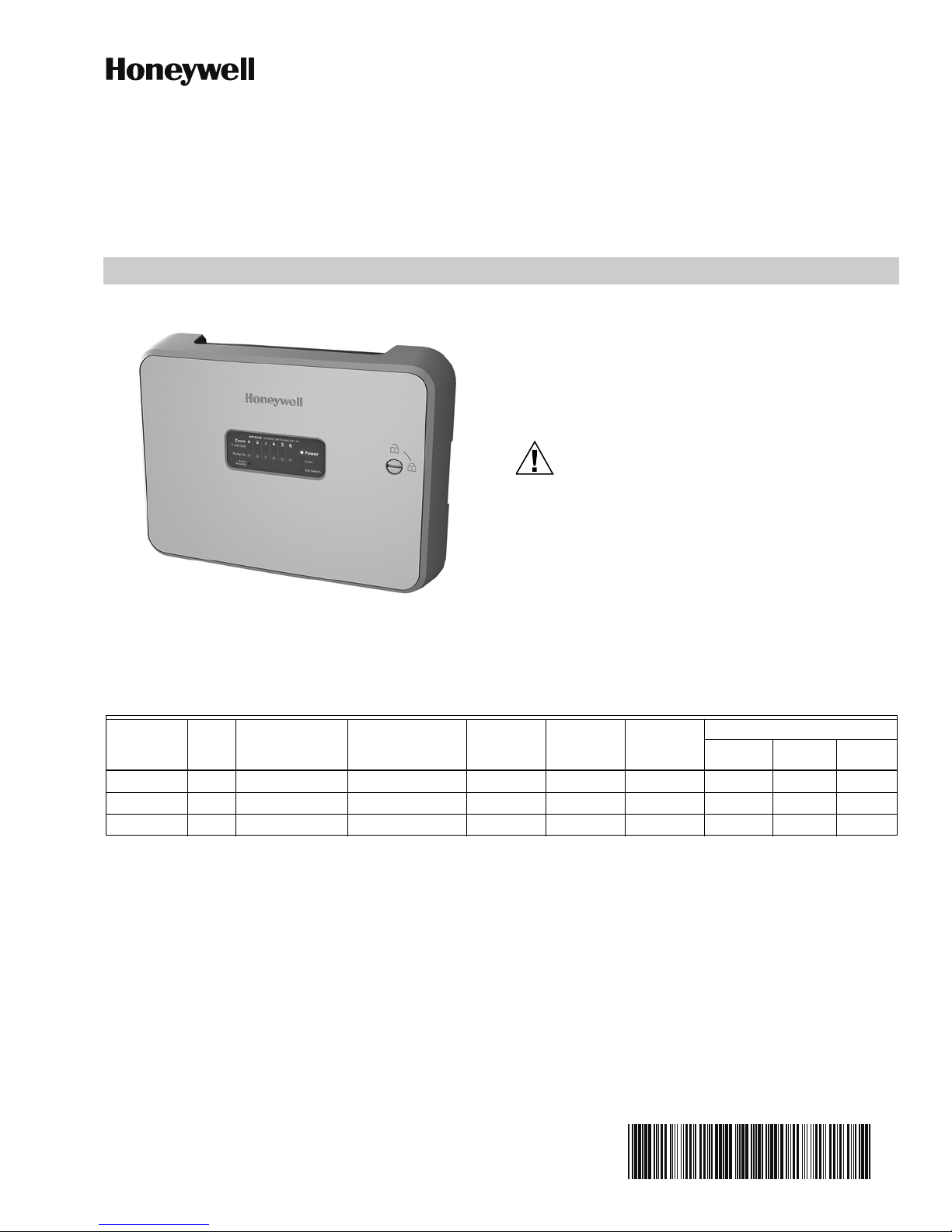
HPSR10*
CAUTION
HONEYWELL HYDRONIC PRO
SWITCHING RELAY PANEL
INSTALLATION INSTRUCTIONS
WHAT'S IN THE BOX?
• Hydronic Zone Panel
• Mounting Hardware (3 Screws and 3 Wall Anchors)
• 1, 2-Amp Fuse; 1, 6-Amp Fuse
• Install Manuals (English & French)
1. Disconnect power supply before beginning
installation to prevent electrical shock or
equipment damage.
2. Use copper conductors only.
3. Use only NEC Class 1 wire for all line voltage
wiring connections. Class 1 wires must be
rated for at least 167 °F (75 °C).
4. For installation by professionals only.
PANEL SPECIFICATIONS
Table 1.
Model Zones Transformers Input Power
HPSR103 3 (1) 24V 40VA 120VAC, 60Hz, 1 15 amps 6 Amp Yes 11-3/4" 8-3/4" 2-1/8"
HPSR104 4 (1) 24V 40VA 120VAC, 60Hz, 1 20 amps 6 Amp Yes 11-3/4" 8-3/4" 2-1/8"
HPSR106 6 (1) 24V 40VA 120VAC, 60Hz, 1 20 amps 6 Amp Yes 11-3/4" 8-3/4" 2-1/8"
NOTES:
• All circulator relay connections, including ZC/ZR, are rated for 5A full load and 30A locked rotor (1/6 to 1/2HP
depending on technology) at 120VAC. Check circulator plate ratings to ensure full load current is not exceeded.
• End switch connections are rated 24V, 1 Amp.
• All thermostat connections supply a 24V Class 2 output.
Maximum
Combined
Load
Pump
Fuse
Priority
Zone
Control
Type 1 Enclosure
Width Height Depth
Page 2
HPSR10*
M37084
M37085
M37086
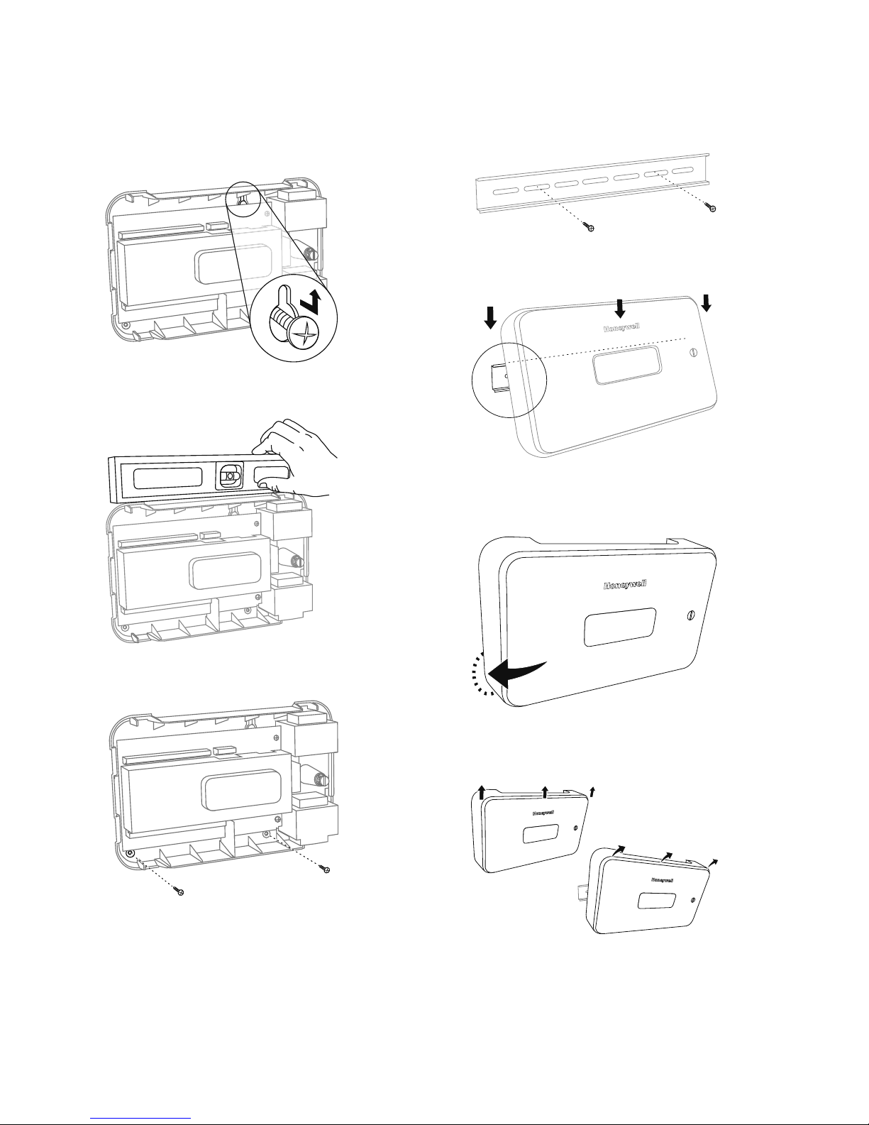
MOUNTING
Hang Hole Flow
1. Hang the panel on a wall-mounted screw.
Fig. 1.
2. Level the panel.
Din Rail Flow
1. Mount the DIN rail as per manufacturers instruc-
tions.
Fig. 4.
2. Hang panel by the tabs on the rail’s top edge.
M37083
M37087
Fig. 5.
3. Snap into rail by pressing the bottom of panel
against the wall.
Fig. 2.
3. Put the 2 bottom screws in.
Fig. 3.
M37088
Fig. 6.
4. To remove, lift up on panel and pull the top away
from the wall.
M37089
Fig. 7.
33-00331EF—05 2
Page 3

HPSR10*
R: 24V Hot (Commonly Red)
W: Heat (Commonly White)
C: Common 24V (Commonly Blue)
R W C
M37090
WIRING AND SETUP
Power Input
Honeywell Hydronic Panels include a convenient wiring
terminal for wiring 120V/60Hz/1Ph power. These
terminals, found at the bottom left side of the panel,
provide power to the transformer and all pumps installed
on the system.
Status Indicators
Honeywell Hydronic Panels feature Advanced Status
Lighting. This includes a transformer status light on the
status panel, and an Input Power Status Light near the
bottom left corner of the Zone Panel. These indicators
show the Power Status of the Panel at all times.
NOTE: Line volt LED is not visible with mylar cover
installed.
Zone Pump
Honeywell Hydronic Panels are compatible with common
zone Pumps and can be wired in as show in the wiring
diagrams on pages 4 and 5.
Thermostat Compatibility
THE HPSR10* zone panels are compatible with electronic,
power stealing, and electro mechanical thermostats.
Dedicated R and W terminals provide heat call messages
from the thermostat to the zone panel and with C terminal
may also provide auxiliary 24V power to electronic
thermostats.
Priority Override
Honeywell Hydronic Panels support priority operation and
can be enabled with the use of a switch located in the top
right section of the panel labeled "Priority Zone".
When priority operation is enabled, the panel employs a
priority override function which operates as shown below:
1. If a priority zone calls for 60 continuous minutes,
priority operation is disabled and control is returned
to each zone.
2. Once the priority zone satisfies, priority override is
disabled and standard operation resumes.
Grounding
A grounding bar has been provided below pump
connection terminal blocks.
NOTE: It is up to the installer to ensure that the 40VA per
transformer limit is not exceeded.
Additionally Honeywell Hydronic Panels are compatible
with Honeywell Equipment Interface Modules in
installations were sufficient wiring is not available.
Fig. 8.
NOTE: For power stealing thermostats, wire to R and W
on the zone panel. There are no additional components required to make these thermostats
function. For all thermostats that require a C wire
for power there is a C terminal available on the
panel for each thermostat.
3 33-00331EF—05
Page 4

HPSR10*
M37092
R W C
ZONE 1
(PRIOR ITY)
R W C
R W C
R W C
R W C
R W C
ZONE 2 ZONE 3 ZONE 4 ZONE 5 ZONE 6
T T
T T
BOILER
ON OFF ON OFF
24V THERMOSTAT CONNECTIONS
120 VAC PUMP CONNECTIONS
LIN E VOLTA GE
IN
LIN E VOLT
STATUS
POWER IN
24 VAC
120 VAC POWER TO
TRA NSFORMER
HPSR106
SIX ZONE
SWITCHING RELAY
LOW LIMIT
SWITCH
ZONE 6 FUSE
END SW ITC H
FUSE
40 VA
120 VAC INPUT
N
H
FACTORY
INSTALLED
JUMPER
TO BOI LER
TO DHW
Zone
T-stat Cal l
Pump On
DHW Prior ity
123456
Power
Boil er
End Switch
HWSR506 6 ZONE PUMP CONTROLLER
ZR
ZC
2 AMP
TRANSFORMER
FUSE
ZONE 1
FUSE
ZONE 2
FUSE
ZONE 3
FUSE
ZONE 4
FUSE
ZONE 5
FUSE
PRIORITY
END
SWITCH
PRIORITY
END
SWITCH
PRIORITY
ZONE
ZONE 1
(PRIOR ITY)
ZONE 2
ZONE 3
ZONE 4 ZONE 5
ZONE 6
GROUNDING BAR
INCLUDED
FOR GROUNDING
THERMOSTAT WIRING
CONNECTED
THERMOSTAT WIRING
NON-CONNECTED
OR POWER STEALING
Standard Wiring Layout
Below wiring diagrams represent a 6 zone pump panel and a 4 zone pump panel. Wiring diagram for the 3 zone pump
panel is identical to the 4 zone pump panel but with zone 4 depopulated.
NOTE: In addition to the low limit switch, each zone pump connection is protected by a 6 Amp fuse.
NOTE: In addition to the low limit switch, each zone pump connection is protected by a 6 Amp fuse.
THERMOSTAT WIRING
NON-CONNECTED
OR POWER STEALING
R W C R W C R W C R W C
ZONE 1
ZONE 2 ZONE 3 ZONE 4
(PRIOR ITY)
24V THERMOSTAT CONNECTIONS
HPSR104
FOUR ZONE
PUMP CONTROLLER
LIN E VOLT
STATUS
LIN E VOLTA GE
IN
GROUNDING BAR
FOR GROUNDING
(PRIOR ITY)
N
120 VAC INPUT
H
INCLUDED
ZONE 1
FUSE
ZONE 1
THERMOSTAT
WIRING
CONNECTED
Zone
T-stat Call
Pump On
DHW Priority
120 VAC PUMP CONNECTIONS
FUSE
ZONE 3
ZONE 3
FUSE
ZONE 4
ZONE 4
FUSE
ZONE 2
ZONE 2
T T
BOIL ER
PRIORITY
SWITCH
1234
Fig. 9.
TO BOI LER
TO DHW
T T
ON OFF ON OFF
PRIORITY
END
END
SWITCH
END SW ITC H
FUSE
BOIL ER END
SWITCH
ZR
FACTORY
INSTALLED
JUMPER
Fig. 10.
PRIORITY
ZC
ZONE
POWER IN
24 VAC
Power
Boiler
End Switch
2 AMP
TRANSFORMER
FUSE
120 VAC POWER TO
TRA NSFORMER
40 VA
M37203
33-00331EF—05 4
Page 5

HPSR10*
T-STAT
CALL
STATUS OF
ZR/ZC
CLOSED
BOILER RELAY=ON
END SWITCH=ON
ZONE PUMP=OFF
OPEN
NO PRIORITY ZONE OR PRIORITY END SWITCH
BOILER RELAY=ON
END SWITCH=ON
ZONE PUMP=ON
M37144
Boiler Controls
Honeywell Hydronic Panels are capable of managing boilers with DHW priority. The panel features two isolated end
switches labeled Boiler and End Switch for TT outputs to the boiler. Two slide switches are available to provide simple
programing of the end switches to meet the desired application. See the operational matrix below detailing functionality
of the switches.
Additionally, this panel features a LOW LIMIT input which must be closed for pumps to be activated. This input comes
with a factory installed jumper for cold start boiler operation when the controlling Aquastat has a HIGH LIMIT only. If the
installed boiler requires warm up time then this jumper should be removed and wired to the boiler.
Fig. 11.
PRIORITY ZONE, NO PRIORITY END SWITCH
T-STAT
CALL
WAIT FOR
PRIORITY ZONE
TO SATISFY
DEACTIVATE ALL
OTHER ZONES
PRIORITY ZONE?
IS PRIORITY
YES
YES
IS THIS THE
NO
ACTIVE?
NO
STATUS OF
ZR/ZC
CLOSED
OPEN
BOILER RELAY = ON
END SWITCH = ON
ZONE PUMP = ON
BOILER RELAY = ON
END SWITCH = ON
ZONE PUMP = OFF
M37145
T-STAT
CALL
WAIT FOR
PRIORITY ZONE
TO SATISFY
DEACTIVATE ALL
OTHER ZONES
YES
PRIORITY ZONE?
NO
YES
Fig. 12.
PRIORITY ZONE, PRIORITY END SWITCH
STATUS OF
ZR/ZC
IS THIS THE
IS PRIORITY
ACTIVE?
NO
OPEN
STATUS OF
ZR/ZC
OPEN
CLOSED
Fig. 13.
CLOSED
BOILER RELAY = ON
END SWITCH = ON
ZONE PUMP = ON
BOILER RELAY = ON
END SWITCH = ON
ZONE PUMP = OFF
BOILER RELAY = ON
END SWITCH = OFF
ZONE PUMP = ON
BOILER RELAY = ON
END SWITCH = OFF
ZONE PUMP = OFF
M37146
5 33-00331EF—05
Page 6

HPSR10*
M37098
Zone
T-s tat Call
Pump On
DHW Priority
123456
Power
Boiler
End Switch
HWSR506 6 ZONE PUMP CONTROLLER
M37301
TROUBLESHOOTING
Status Label
Fig. 14.
This panel provides a status indicator label which is
available both when the panel cover is in place and
removed. Descriptions of the indictor LED's are shown
below:
T-stat Call LED's indicate the thermostat associated with
that specific zone is calling for heat.
Pump On LED's indicate which circulators in the system
are being energized (or powered).
Mylar cover
DHW Priority LED indicate the priority zone is active and
calling.
Power LED indicates the transformer is powered.
Boiler and End Switch LED's indicate when each relay is
energized and calling for heat.
Table 2. Color Chart.
T-Stat
Call
Blue Green White White Red
Pump On
DHW
Priority
Power
Boiler &
End
Switch
REGULATORY INFORMATION
This device complies with part 15 of the FCC rules.
Operation is subject to the following two conditions:
(1) This device may not cause harmful interference, and
(2) this device must accept any interference received,
including interference that may cause undesired
operation.
5-YEAR LIMITED WARRANTY
Honeywell warrants this product to be free from defects in the workmanship or materials, under normal use and service,
for a period of five (5) years from the date of purchase by the consumer. If at any time during the warranty period the
product is determined to be defective or malfunctions, Honeywell shall repair or replace it (at Honeywell's option).
This warranty does not cover removal or reinstallation costs. This warranty shall not apply if it is shown by Honeywell that
the defect was caused by damage which occurred while the product was in the possession of a consumer.
All details on this limited warranty are explained in our Tradeline Catalog. If you have any questions, please write
Honeywell Customer Care, 1985 Douglas Dr, Golden Valley, MN 55422 or call 1-800-468-1502.
In the U.S.:
Honeywell
1985 Douglas Drive North
Golden Valley, MN 55422
customer.honeywell.com
Fig. 15. Mylar cover.
® U.S. Registered Trademark
© 2018 Honeywell International Inc.
33-00331EF—05 M.S. Rev. 03-18
Printed in United States
Page 7

HPSR10*
MISE EN GARDE
PANNEAU DE RÉGULATEURS DE POMPES
HYDRONIQUE PRO HONEYWELL
INSTRUCTIONS D’INSTALLATION
CONTENU DE L’EMBALLAGE
• Panneau de régulateurs de pompes de zone
hydronique
• Quincaillerie de montage (3 vis et 3 ancrages muraux)
• 1 fusible de 2 A; 1 fusible de 6 A
• Manuels d’installation (anglais et français)
1. Débranchez l’alimentation électrique avant de
commencer l’installation afin de prévenir les
chocs électriques ou les dommages matériels.
2.
Utilisez uniquement des conducteurs en cuivre.
3. Utilisez uniquement un câble NEC de classe 1
pour tous les raccordements de câblage de
tension secteur. Les câbles de classe 1 doivent
être adaptés à une température d’au moins
75 °C (167 °F).
4. Pour installation par des professionnels
seulement.
SPÉCIFICATIONS DU PANNEAU
Tableau 1.
Charge
Modèle Zones Transformateurs Alimentation
HPSR103 3 (1) 24 V 40 VA 120 V c. a.,
60 Hz, 1
HPSR104 4 (1) 24 V 40 VA 120 V c. a.,
60 Hz, 1
HPSR106 6 (1) 24 V 40 VA 120 V c. a.,
60 Hz, 1
REMARQUE :
• Tous les raccordements du relais du circulateur, y compris les ZC/ZR, sont adaptés à un rotor bloqué de 30 A et à une
charge nominale de 5 A (1/6 à 1/2 HP en fonction de la technologie) à 120 V c. a. Vérifiez les valeurs sur la plaque du
circulateur afin de vous assurer que le courant nominal n’est pas dépassé.
• Les raccordements de l’interrupteur d’extrémité sont adaptés à du 24 V, 1 A.
• Tous les raccordements du thermostat alimentent une sortie de classe 2 de 24 V.
combinée
maximale
15 A 6 A Oui 11-3/4" 8-3/4" 2-1/8"
20 A 6 A Oui 11-3/4" 8-3/4" 2-1/8"
20 A 6 A Oui 11-3/4" 8-3/4" 2-1/8"
Fusible
de la
pompe
Commande
des zones
prioritaires
Boîtier de type 1
Largeur Hauteur Profondeur
Page 8

HPSR10*
M37084
M37085
M37086
MONTAGE
Trou de suspension
1. Accrochez le panneau à une vis fixée au mur.
M37083
Fig. 1.
2. Mettez le panneau de niveau.
Rail DIN
1. Montez le rail DIN conformément aux instructions
du fabricant.
Fig. 4.
2. Suspendez le panneau par les languettes sur le bord
supérieur du rail.
M37087
Fig. 5.
Fig. 2.
3. Installez les 2 vis du bas.
Fig. 3.
3. Emboîtez le panneau dans le rail en appuyant le bas
du panneau contre le mur.
M37088
Fig. 6.
4. Pour retirer le panneau, soulevez-le et écartez la
partie supérieure du mur.
33-00331EF—05 2
M37089
Fig. 7.
Page 9

HPSR10*
CÂBLAGE ET
CONFIGURATION
Alimentation du panneau
Les panneaux hydroniques Honeywell comprennent une
borne de câblage pratique pour une alimentation de
120V/60Hz/1Ph. Ces bornes, situées dans le côté
inférieur gauche du panneau, fournissent l’alimentation
au transformateur et à toutes les pompes installées sur le
système.
Témoins d’état
Les panneaux hydroniques Honeywell intègrent des
témoins d’état de pointe. Il y a un témoin pour le
transformateur sur le circuit de contrôle et un témoin
d'alimentation situé près du coin inférieur gauche du
circuit de contrôle de zone. Ces témoins affichent l’état
d’alimentation du panneau en tout temps.
REMARQUE : le témoin de tension secteur n’est pas
visible lorsque le couvercle en mylar est
installé.
Pompe de zone
Les panneaux hydroniques Honeywell sont compatibles
avec les pompes de zone classiques et peuvent être
raccordés comme indiqué dans les schémas de câblage
aux pages 4 et 5.
Dérivation prioritaire
Les panneaux hydroniques Honeywell offrent une
fonction prioritaire qui peut être activée à l’aide d’un
interrupteur situé dans la partie supérieure droite du
panneau marquée « Zone prioritaire ».
Lorsque le fonctionnement prioritaire est activé, le
panneau recourt à une fonction de dérivation prioritaire
qui agit comme suit :
1. Si une zone prioritaire nécessite de la chaleur
pendant 60 minutes, le fonctionnement prioritaire
est désactivé et le contrôle est rétabli pour chaque
zone.
2. Une fois les besoins de la zone prioritaire satisfaits,
la dérivation prioritaire est désactivée et le
fonctionnement classique est rétabli.
Mise à la terre
Une barre de mise à la terre a été fournie en dessous des
borniers de raccordement de la pompe.
Compatibilité avec les thermostats
Les panneaux HPSR10* sont compatibles avec les
thermostats électroniques, les thermostats
électromécaniques et les thermostats qui n'ont pas besoin
du fil commun (fil C) pour l'alimentation. Chaque
thermostat a ses propres bornes R et W pour permettre au
thermostat de transmettre des demandes de chauffage au
panneau. La borne C offre du 24 V c. a aux thermostats
électroniques qui ont besoin de l'alimentation.
REMARQUE : il incombe à l’installateur de veiller à ce que
la limite de 40 VA par transformateur ne soit
pas dépassée.
En outre, les panneaux hydroniques Honeywell sont
compatibles avec les modules d’interface de l’équipement
Honeywell dans les installations ne disposant pas de
suffisamment de câblage.
R : 24 V (généralement rouge)
W : Chauffage (généralement blanc)
C : Commun (généralement bleu)
R W C
Fig. 8.
REMARQUE : Pour les thermostats qui n'ont pas besoin
du fil commun (fil C) pour l'alimentation,
branchez chaque thermostat au R et au W
du panneau. Ces thermostats n'ont besoin
d'aucun autre accessoire pour fonctionner.
Pour les thermostats qui ont besoin du fil
commun (fil C) pour l’alimentation, une
borne C est disponible sur le panneau pour
chaque thermostat.
MF37090
3 33-00331EF—05
Page 10

HPSR10*
MF37092
R W C
ZONE 1
(PRIORITÉ)
R W C
R W C
R W C
R W C
R W C
ZONE 2 ZONE 3 ZONE 4 ZONE 5 ZONE 6
T T
T T
CHAUDIÈRE
RACCORDEMENTS DES THERMOSTATS DE 24 V
RACCORDEMENTS DES POMPES 120 V c. a.
ALIMENTATION
ÉTAT DE LA
TENSION
SECTEUR
120 V c.a. (AU TRANSFO.)
RÉGULATEUR DE
POMPES À
6 ZONES HPSR106
INTERRUPTEUR DE
LIMITE INFÉRIEURE
FUSIBLE ZONE 6
FUSIBLE
INTERRUPTEUR
D’EXTRÉMITÉ
40 VA
ENTRÉE 120 V c. a.
N
H
CAVALIER POSÉ
EN USINE
VERS LA CHAUDIÈRE
VERS L’ECS
Zone
Demande du
thermostat
Pompe activée
Priorité de l’ECS
123456
Priorité
de l’ECS
Chaudière
Interrupteur
d’extrémité
RÉGULATEUR DE POMPE 6 ZONES HWSR506
ZR
ZC
FUSIBLE DE
TRANSFORMATEUR
2 A
FUSIBLE
ZONE 1
FUSIBLE
ZONE 2
FUSIBLE
ZONE 3
FUSIBLE
ZONE 4
FUSIBLE
ZONE 5
INTERRUPTEUR
D’EXTRÉMITÉ
PRIORITAIRE
INTERRUPTEUR
D’EXTRÉMITÉ
PRIORITAIRE
ZONE
PRIORITAIRE
ZONE 1
(PRIORITÉ)
ZONE 2
ZONE 3
ZONE 4 ZON E 5
ZONE 6
CÂBLE DE MISE À LA TERRE ET
CONNECTEUR POUR LA MISE À
LA TERRE INCLUS.
CÂBLAGE DU THERMOSTAT
AVEC LE FIL C
CÂBLAGE DU THERMOSTAT
SANS LE FIL C
MARCHE/ARRÊT MARCHE/ARRÊT
24 V c.a.
(DU TRANSFO.)
Disposition standard du câblage
Les schémas de câblage ci-dessous représentent un panneau de régulateurs de pompes à 6 zones et un à 4 zones. Les
schémas de câblage pour le panneau à 3 zones est similaire à celui à 4 zones.
Fig. 9.
REMARQUE : en plus de l'interrupteur de limite inférieure, chaque raccordement de pompe est protégé par un fusible de
6 A.
(PRIORITÉ)
RACCORDEMENTS DES THERMOSTATS DE 24 V
ÉTAT DE LA
TENSION
SECTEUR
ALIMENTATION
CÂBLE DE MISE À LA TERRE ET
CONNECTEUR POUR LA MISE À
LA TERRE INCLUS.
CÂBLAGE DU THERMOSTAT
SANS LE FIL C
R W C R W C R W C R W C
ZONE 1
ZONE 2 ZONE 3 Z ONE 4
RÉGULATEUR DE
POMPES À 4 ZONES
HPSR104
N
H
RACCORDEMENTS DES POMPES 120 V c. a.
ZONE 1
FUSIBLE
ZONE 1
(PRIORITÉ)
ENTRÉE 120 V c. a.
FUSIBLE
ZONE 2
CÂBLAGE DU
THERMOSTAT
AVEC LE FIL C
Demande du
thermostat
Pompe activée
Priorité de l’ECS
ZONE 3
ZONE 2
FUSIBLE
ZONE 3
Zone
ZONE 4
FUSIBLE
ZONE 4
T T
CHAUDIÈRE
1234
T T
MARCHE/ARRÊT MARCHE/ARRÊT
INTERRUPTEUR
D’EXTRÉMITÉ
PRIORITAIRE
D’EXTRÉMITÉ
PRIORITAIRE
FUSIBLE INTERRUPTEUR
D’EXTRÉMITÉ
INTERRUPTEUR
D’EXTRÉMITÉ DE LA
CHAUDIÈRE
ZR
CAVALIER POSÉ
EN USINE
VERS LA CHAUDIÈRE
VERS L’ECS
INTERRUPTEUR
ZONE
PRIORITAIRE
Alimentation
Chaudière
Interrupteur
d’extrémité
120 V c.a.
(AU TRANSFO.)
ZC
FUSIBLE DE
TRANSFORMATEUR
2 A
24 V c.a.
(DU TRANSFO.)
40 VA
MF37203
REMARQUE : en plus de l'interrupteur de limite inférieure, chaque raccordement de pompe est protégé par un fusible de
33-00331EF—05 4
6A.
Fig. 10.
Page 11

HPSR10*
ZONE PRIORITAIRE, INTERRUPTEUR D’EXTRÉMITÉ PRIORITAIRE
MF37146
DEMANDE DU
THERMOSTAT
STATUT
DE ZR/ZC
FERMÉ
RELAIS DE LA CHAUDIÈRE = MARCHE
INTERRUPTEUR D’EXTRÉMITÉ = MARCHE
POMPE DE LA ZONE = MARCHE
EST-CE UNE ZONE
PRIORITAIRE ?
DÉSACTIVER TOUTES
LES AUTRES ZONES
OUI
LA PRIORITÉ
EST-ELLE
ACTIVE ?
NON
NON
ATTENDRE QUE LES
BESOINS DE LA
ZONE PRIORITAIRE
SOIENT SATISFAITS
OUI
STATUT
DE ZR/ZC
FERMÉ
OUVERT
OUVERT
RELAIS DE LA CHAUDIÈRE = MARCHE
INTERRUPTEUR D’EXTRÉMITÉ = MARCHE
POMPE DE LA ZONE = ARRÊT
RELAIS DE LA CHAUDIÈRE = MARCHE
INTERRUPTEUR D’EXTRÉMITÉ = ARRÊT
POMPE DE LA ZONE = MARCHE
RELAIS DE LA CHAUDIÈRE = MARCHE
INTERRUPTEUR D’EXTRÉMITÉ = ARRÊT
POMPE DE LA ZONE = ARRÊT
Contrôles de la chaudière
Les panneaux hydroniques Honeywell permettent de gérer les chaudières avec une priorité pour l’ECS. Le panneau est
doté de deux interrupteurs d’extrémité isolés marqués « Chaudière » et « Interrupteur d’extrémité » pour les sorties TT
vers la chaudière. Deux interrupteurs sont disponibles afin de faciliter la programmation des interrupteurs d’extrémité et
ainsi obtenir l’application souhaitée. Consultez la matrice de fonctionnement ci-dessous afin d’en savoir plus sur le
fonctionnement des interrupteurs.
En outre, ce panneau dispose d'une entrée de LIMITE INFÉRIEURE qui doit être fermée pour permettre l’activation des
pompes. Cette entrée est livrée avec un cavalier posé en usine pour un démarrage à froid de la chaudière lorsque le
contrôleur Aquastat dispose d’une LIMITE SUPÉRIEURE uniquement. Si la chaudière installée requiert un temps de
préchauffage, alors ce cavalier doit être retiré et raccordé à la chaudière.
AUCUNE ZONE PRIORITAIRE OU INTERRUPTEUR D’EXTRÉMITÉ PRIORITAIRE
RELAIS DE LA CHAUDIÈRE = MARCHE
INTERRUPTEUR D’EXTRÉMITÉ = MARCHE
POMPE DE LA ZONE = MARCHE
RELAIS DE LA CHAUDIÈRE = MARCHE
INTERRUPTEUR D’EXTRÉMITÉ = MARCHE
POMPE DE LA ZONE = ARRÊT
MF37144
DEMANDE DU
THERMOSTAT
STATUT DE
ZR/ZC
FERMÉ
OUVERT
Fig. 11.
ZONE PRIORITAIRE, AUCUN INTERRUPTEUR D’EXTRÉMITÉ PRIORITAIRE
DEMANDE DU
THERMOSTAT
ATTENDRE QUE
LES BESOINS DE
LA ZONE PRIORITAIRE
SOIENT SATISFAITS
OUI
DÉSACTIVER TOUTES
LES AUTRES ZONES
OUI
EST-CE UNE ZONE
PRIORITAIRE ?
NON
LA PRIORITÉ
EST-ELLE
ACTIVE ?
STATUT
DE ZR/ZC
NON
Fig. 12.
Fig. 13.
5 33-00331EF—05
FERMÉ
OUVERT
RELAIS DE LA CHAUDIÈRE = MARCHE
INTERRUPTEUR D’EXTRÉMITÉ = MARCHE
POMPE DE LA ZONE = MARCHE
RELAIS DE LA CHAUDIÈRE = MARCHE
INTERRUPTEUR D’EXTRÉMITÉ = MARCHE
POMPE DE LA ZONE = ARRÊT
MF37145
Page 12

HPSR10*
MF37098
Zone
Demande du
thermostat
Pompe activée
Priorité de l’ECS
123456
Alimentation
Chaudière
Interrupteur
d’extrémité
RÉGULATEUR DE POMPES À 6 ZONES HWSR506
Priorité
zone 1
Marche/
Arrêt
Marche/
Arrêt
Chaudière
Interrupteur
d’extrémité
Interrupteur
d’extrémité
prioritaire
Zone
prioritaire
CIRCULATEURS 120 V C.A.
Priorité
zone 1
Entrée
120 V c.a.
120 V c.a.
THERMOSTATS 24 V CA
MF37301
DÉPANNAGE
Témoin d’état
Fig. 14.
Ce panneau affiche un témoin d’état, que le couvercle soit
placé ou non. Une description des témoins est fournie
ci-dessous :
Le témoin « Demande du thermostat » indique que le
thermostat associé à cette zone spécifique, demande du
chauffage.
Le témoin « Pompe activée » indique lesquels des
circulateurs du système sont alimentés.
Le témoin « Priorité de l’ECS » indique que la zone
prioritaire est active et demande du chauffage.
Le témoin « Alimentation » indique que le transformateur
est alimenté.
Les témoins « Chaudière » et « Interrupteur d’extrémité »
indiquent que chaque relais est alimenté et demande du
chauffage.
Tableau 2. Panneau des couleurs.
Demande du
thermostat
Pompe
activée
Priorité de
l’ECS
Alimentation
Chaudière et
Interrupteur
d’extrémité
Bleu Vert Blanc Blanc Rouge
INFORMATIONS
RÉGLEMENTAIRES
Cet appareil est conforme à la partie 15 des
réglementations de la FCC. Son fonctionnement est
soumis aux deux conditions suivantes :
(1) Ce dispositif ne peut pas causer d’interférences
dangereuses, et
(2) ce dispositif ne doit accepter aucune interférence
reçue, notamment les interférences à l’origine d’un
fonctionnement indésirable.
Couvercle en mylar
Fig. 15. Couvercle en mylar.
GARANTIE LIMITÉE DE 5 ANS
Honeywell garantit ce produit contre tout vice de fabrication ou de matériau dans la mesure où il en est fait une utilisation
et un entretien convenables, et ce, pour cinq (5) ans à partir de la date d’achat par le consommateur. En cas de défaillance
ou de mauvais fonctionnement pendant la période de garantie, Honeywell remplacera ou réparera le produit (à sa
discrétion).
La présente garantie ne couvre pas les frais de retrait ou de réinstallation. La présente garantie ne s’appliquera pas s’il est
démontré par Honeywell que la défaillance est due à un endommagement du produit qui s'est produit lorsque le
consommateur l’avait en sa possession.
Tous les détails concernant la garantie limitée sont inclus dans notre catalogue Tradeline. Si vous avez des questions,
veuillez écrire à Honeywell Customer Care, 1985 Douglas Dr, Golden Valley, MN 55422 ou composez le 1-800-468-1502.
Aux États-Unis :
Honeywell
1985 Douglas Drive North
Golden Valley, MN 55422
customer.honeywell.com
® Marque de commerce déposée aux États-Unis
© 2018 Honeywell International Inc.
33-00331EF—05 M.S. Rev. 03-18
Imprimé aux États-Unis
 Loading...