

Honeywell
12 Clintonville Road
Northford, CT 06472-1610
http://www.honeywellpower.com
Power Supply/Battery Charger
PN 52263:C 1/10/08 ECN 08-029
HPL624
Product Installation Document
1 Introduction
The HPL624 power supply/battery charger converts a low voltage AC input into an output of 6 VDC or 12 VDC @ 1.2
amps of continuous supply current or 24 VDC @ 750 mA of continuous supply current. This general purpose linear
power supply can provide additional power for a variety of applications such as access control, security and CCTV system
accessories.
2 Specifications
• Switch selectable for 6 VDC, 12 VDC or 24 VDC output.
• 1.2 amps of continuous supply current at 6 VDC or 12 VDC.*
• 750 mA of continuous supply current at 24 VDC.*
• Output that is filtered and electronically regulated.
• Built-in charger for sealed lead acid or gel type batteries.
• Maximum charge current of 500 mA.
If a battery charger is used, subtract max charge current of
500 mA from total to determine allowable load.
• Automatic switchover to stand-by battery upon AC fail.
• PTC battery protection.
• Thermal and short circuit protection with auto reset.
• LED indicators for AC input and DC output.
• Compact design (board dimension 3"L x 2.5"W x 1.5"H).
HPL624.wmf
• Battery leads and foam mounting tape included.
*Specified at 25ºC ambient.
3 Voltage Output and Transformer Selection
Output Voltage/Current
12 VDC @ 1.2 amps continuous supply current Closed Closed 16.5VAC / 40 VA
24 VDC @ 750 mA continuous supply current Open Closed 24VAC / 40 VA
6 VDC @ 1.2 amps continuous supply current Closed Open 12VAC / 20 VA
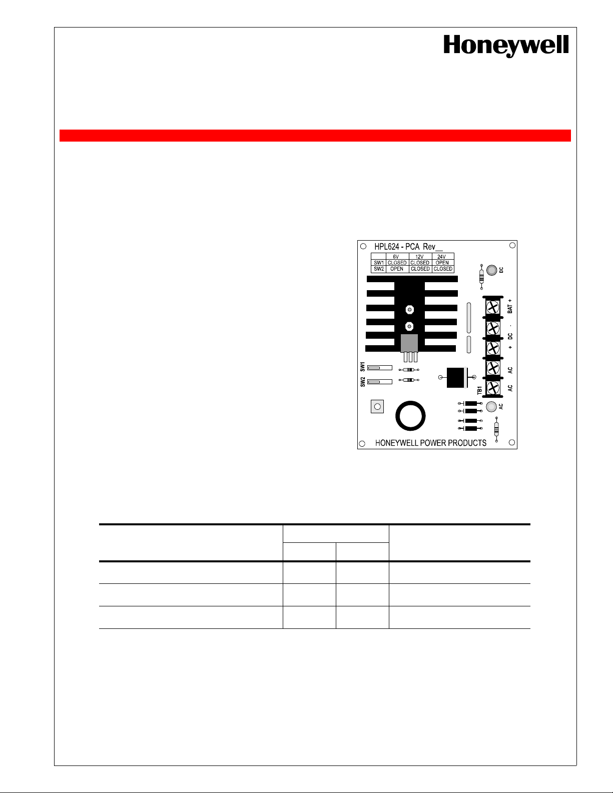
Switch
Tran sformer Requirements
SW1 SW2
DC LED
TB1
BAT +
DC –
DC +
AC
AC
AC LED
(model HTP1640)
(model HTP2440)
(model HTP1220)

4 Installation Instructions
The HPL624 should be installed in accordance with the National Electrical Code and Local Authority Having
Jurisdiction.
1. Mount the HPL624 Power Supply/Charger in the desired enclosure and location using supplied tape or optional
Snaptrack HST34. If mounted using screws, use #6 screws and 3/8" non-metallic spacer or supplied foam tape.
2. The HPL624 is factory set for 12 VDC. Refer to preceding table to change to 6 VDC or 24 VDC output.
3. Connect the proper transformer to terminals labeled [AC] (refer to preceding table for correct transformer selection).
4. Use 18 AWG or larger wire for all power connections (battery, DC output).
IMPORTANT! Keep a minimum spacing of 0.25" (6.35 mm) between all power-limited and nonpower-limited
wiring such as the 115VAC/60Hz Input and the battery wiring.
5. While carefully observing polarity, connect the devices to be powered to the terminals labeled [+ DC] and [DC -].
Note: To avoid potential damage, it is important to measure the output voltage prior to connecting any devices.
6. Connect the battery using the supplied battery leads to the terminals labeled [BAT +] and [DC -].
Use two (2) 12 VDC batteries connected in series for 24 VDC operation.
Note: If batteries are not used, a loss of AC will result in a loss of output voltage.
7. After batteries and AC power have been applied, both LEDs light.
8. It is recommended that the output current be measured to ensure that it does not exceed the rated maximum current.
5 LED Indicators
Red (DC) Green (AC) Power Supply Status
ON ON Normal operating condition.
ON OFF Loss of AC, Stand-by battery supplying power.
OFF ON No DC output. Short circuit or thermal overload condition.
OFF OFF No DC output. Loss of AC. Discharged or no battery present.
6 Terminal Identification
Terminal Label Function/Description
AC AC Low voltage AC input. (Refer to Voltage Output/Transformer Selection Table.)
– DC + 6 VDC – 12 VDC @ 1.2 amps continuous supply current output.
+ BAT – Stand-by battery connections. Maximum charge rate 500 mA.
For additional information:
• Visit our website at http://www.honeywellpower.com
• Contact Technical Support at (877) HPP-POWR
• E-mail us at hpp_techserv@honeywell.com
24 VDC @ 750 mA continuous supply current output.
2 HPL624 Power Supply/Charger — P/N 52263:C 1/10/08
 Loading...