

Page 1

Power Products
HPFF12(E)/HPFF12CM(E)
Notification Appliance Circuit Expander
Instruction Manual
Document 53576 Rev: B3
10/1/2018 ECN: 18-476
Page 2

Fire Alarm & Emergency Communication System Limitations
While a life safety system may lower insurance rates, it is not a substitute for life and property insurance!
An automatic fire alarm system—typically made up of smoke
detectors, heat detectors, manual pull stations, audible warning
devices, and a fire alarm control panel (FACP) with remote notification capability—can provide early warning of a developing fire. Such
a system, however, does not assure protection against property
damage or loss of life resulting from a fire.
An emergency communication system—typically made up of an
automatic fire alarm system (as described above) and a life safety
communication system that may include an autonomous control
unit (ACU), local operating console (LOC), voice communication,
and other various interoperable communication methods—can
broadcast a mass notification message. Such a system, however,
does not assure protection against property damage or loss of life
resulting from a fire or life safety event.
The Manufacturer recommends that smoke and/or heat detectors
be located throughout a protected premises following the
recommendations of the current edition of the National Fire
Protection Association Standard 72 (NFPA 72), manufacturer's
recommendations, State and local codes, and the
recommendations contained in the Guide for Proper Use of System
Smoke Detectors, which is made available at no charge to all
installing dealers. This document can be found at http://
www.systemsensor.com/appguides/. A study by the Federal
Emergency Management Agency (an agency of the United States
government) indicated that smoke detectors may not go off in as
many as 35% of all fires. While fire alarm systems are designed to
provide early warning against fire, they do not guarantee warning or
protection against fire. A fire alarm system may not provide timely or
adequate warning, or simply may not function, for a variety of
reasons:
Smoke detectors may not sense fire where smoke cannot reach
the detectors such as in chimneys, in or behind walls, on roofs, or
on the other side of closed doors. Smoke detectors also may not
sense a fire on another level or floor of a building. A second-floor
detector, for example, may not sense a first-floor or basement fire.
Particles of combustion or “smoke” from a developing fire may
not reach the sensing chambers of smoke detectors because:
• Barriers such as closed or partially closed doors, walls, chimneys, even wet or humid areas may inhibit particle or sm
oke
flow.
•
Smoke particles may become “cold,” stratify, and not reach t
he
c
eiling or upper walls where detectors are located.
• Smoke particles may be blown away from detectors by air outlets, such as air conditioning vents.
• Smoke particles may be drawn into air returns before reachi
ng
t
he detector.
The amount of “smoke” present may be insufficient to alarm smoke
detectors. Smoke detectors are designed to alarm at various levels
of smoke density. If such density levels are not created by a developing fire at the location of detectors, the detectors will not go into
alarm.
Smoke detectors, even when working properly, have sensing limitations. Detectors that have photoelectronic sensing chambers tend
to detect smoldering fires better than flaming fires, which have little
visible smoke. Detectors that have ionizing-type sensing chambers
tend to detect fast-flaming fires better than smoldering fires.
Because fires develop in different ways and are often unpredictable
in their growth, neither type of detector is necessarily best and a
given type of detector may not provide adequate warning of a fire.
Smoke detectors cannot be expected to provide adequate warning
of fires caused by arson, children playing with matches (especially
in bedrooms), smoking in bed, and violent explosions (caused by
escaping gas, improper storage of flammable materials, etc.).
Heat detectors do not sense particles of combustion and alarm
only when heat on their sensors increases at a predetermined rate
or reaches a predetermined level. Rate-of-rise heat detectors may
be subject to reduced sensitivity over time. For this reason, the rateof-rise feature of each detector should be tested at least once per
year by a qualified fire protection specialist. Heat detectors are
designed to protect property, not life.
IMPORTANT! Smoke detectors must be installed in the same
room as the control panel and in rooms used by the system for the
connection of alarm transmission wiring, communications, signaling, and/or power. If detectors are not so located, a developing fire
may damage the alarm system, compromising its ability to report a
fire.
Audible warning devices such as bells, horns, strobes, speakers and displays may not alert people if these devices are located
on the other side of closed or partly open doors or are located on
another floor of a building. Any warning device may fail to alert people with a disability or those who have recently consumed drugs,
alcohol, or medication. Please note that:
• An emergency communication system may take priority over a
fire alarm system in the event of a life safety emergency.
• Voice messaging systems must be designed to meet intelligibility
requirements as defined by NFPA, local codes, and Authoritie
s
Havi
ng Jurisdiction (AHJ).
• Language and instructional requirements must be clearly disseminated on any local displays.
• Strobes can, under certain circumstances, cause seizures in
people with conditions such as epilepsy.
• Studies have shown that certain people, even when they hear a
fire alarm signal, do not respond to or comprehend the meani
ng
of
the signal. Audible devices, such as horns and bells, can hav
e
di
fferent tonal patterns and frequencies. It is the property
owner's responsibility to conduct fire drills and other traini
ng
ex
ercises to make people aware of fire alarm signals an
d
i
nstruct them on the proper reaction to alarm signals.
• In rare instances, the sounding of a warning device can ca
use
t
emporary or permanent hearing loss
.
A
life safety system will not operate without any electrical power. If
AC power fails, the system will operate from standby batteries only
for a specified time and only if the batteries have been properly
maintained and replaced regularly.
Equipment used in the system may not be technically compatible
with the control panel. It is essential to use only equipment listed for
service with your control panel.
Telephone lines needed to transmit alarm signals from a premises
to a central monitoring station may be out of service or temporarily
disabled. For added protection against telephone line failure,
backu
p radio transmission systems are recommended.
The most common cause of life safety system malfunction is inadequate maintenance. To keep the entire life safety system in excellent working order, ongoing maintenance is required per the
manufacturer's recommendations, and UL and NFPA standards. At
a minimum, the requirements of NFPA 72 shall be followed. Environments with large amounts of dust, dirt, or high air velocity require
more frequent maintenance. A maintenance agreement should be
arranged through the local manufacturer's representative. Maintenance should be scheduled as required by National and/or local fire
codes and should be performed by authorized professional life
safety system installers only. Adequate written records of all inspections should be kept.
Limit-D2-2016
2 HPFF12 NAC Expander — P/N 53576:B3 10/1/2018
Page 3

Installation Precautions
Adherence to the following will aid in problem-free installation with long-term reliability:
WARNING - Several different sources of power can be connected to the fire alarm control panel. Disconnect all sources of
power before servicing. Control unit and associated equipment
may be damaged by removing and/or inserting cards, modules, or
interconnecting cables while the unit is energized. Do not attempt
to install, service, or operate this unit until manuals are read and
understood.
CAUTION - System Re-acceptance Test after Software
Changes: To ensure proper system operation, this product must be
tested in accordance with NFPA 72 after any programming operation or change in site-specific software. Re-acceptance testing is
required after any change, addition or deletion of system components, or after any modification, repair or adjustment to system
hardware or wiring. All components, circuits, system operations, or
software functions known to be affected by a change must be 100%
tested. In addition, to ensure that other operations are not inadvertently affected, at least 10% of initiating devices that are not directly
affected by the change, up to a maximum of 50 devices, must also
be tested and proper system operation verified.
This system meets NFPA requirements for operation at 0-49º C/
32-120º F and at a relative humidity . However, the useful life of
the system's standby batteries and the electronic components may
be adversely affected by extreme temperature ranges and humidity.
Therefore, it is recommended that this system and its peripherals
be installed in an environment with a normal room temperature of
15-27º C/60-80º F.
Verify that wire sizes are adequate for all initiating and indicating
device loops. Most devices cannot tolerate more than a 10% I.R.
drop from the specified device voltage.
Like all solid state electronic devices, this system may operate
erratically or can be damaged when subjected to lightning induced
transients. Although no system is completely immune from lightning transients and interference, proper grounding will reduce susceptibility. Overhead or outside aerial wiring is not recommended,
due to an increased susceptibility to nearby lightning strikes. Consult with the Technical Services Department if any problems are
anticipated or encountered.
Disconnect AC power and batteries prior to removing or inserting
circuit boards. Failure to do so can damage circuits.
Remove all electronic assemblies prior to any drilling, filing,
reaming, or punching of the enclosure. When possible, make all
cable entries from the sides or rear. Before making modifications,
verify that they will not interfere with battery, transformer, or printed
circuit board location.
Do not tighten screw terminals more than 9 in-lbs. Over-tightening may damage threads, resulting in reduced terminal contact
pressure and difficulty with screw terminal removal.
This system contains static-sensitive components. Always
ground yourself with a proper wrist strap before handling any circuits so that static charges are removed from the body. Use static
suppressive packaging to protect electronic assemblies removed
from the unit.
Follow the instructions in the installation, operating, and programming manuals. These instructions must be followed to avoid
damage to the control panel and associated equipment. FACP
operation and reliability depend upon proper installation.
Precau-D1-9-2005
FCC Warning
WARNING: This equipment generates, uses, and can radi-
ate radio frequency energy and if not installed and used in
accordance with the instruction manual may cause interference to radio communications. It has been tested and found
to comply with the limits for class A computing devices pursuant to Subpart B of Part 15 of FCC Rules, which is
designed to provide reasonable protection against such
interference when devices are operated in a commercial
environment. Operation of this equipment in a residential
area is likely to cause interference, in which case the user
will be required to correct the interference at his or her own
expense.
Canadian Requirements
This digital apparatus does not exceed the Class A limits for
radiation noise emissions from digital apparatus set out in
the Radio Interference Regulations of the Canadian Department of Communications.
Le present appareil numerique n'emet pas de bruits radioelectriques depassant les limites applicables aux appareils
numeriques de la classe A prescrites dans le Reglement sur
le brouillage radioelectrique edicte par le ministere des
Communications du Canada.
HARSH™, NIS™, and NOTI•FIRE•NET™ are all trademarks; and Acclimate®, FlashScan®, Honeywell®. NOTIFIER®, ONYX®, ONYXWorks®, VeriFire®, and
VIEW® are all registered trademarks of Honeywell International Inc. Microsoft® and Windows® are registered trademarks of the Microsoft Corporation. Chrome™ and
Google™ are trademarks of Google Inc. Firefox® is a registered trademark of The Mozilla Foundation.
©2018 by Honeywell International Inc. All rights reserved. Unauthorized use of this document is strictly prohibited.
HPFF12 NAC Expander — P/N 53576:B3 10/1/2018 3
Page 4

Software Downloads
In order to supply the latest features and functionality in fire alarm and life safety technology to our customers, we make frequent
upgrades to the embedded software in our products. To ensure that you are installing and programming the latest features, we
strongly recommend that you download the most current version of software for each product prior to commissioning any system.
Contact Technical Support with any questions about software and the appropriate version for a specific application.
Documentation Feedback
Your feedback helps us keep our documentation up-to-date and accurate. If you have any comments or suggestions about our online
Help or printed manuals, you can email us.
Please include the following information:
• Product name and version number (if applicable)
• Printed manual or online Help
• Topic Title (for online Help)
• Page number (for printed manual)
• Brief description of content you think should be improved or corrected
• Your suggestion for how to correct/improve documentation
Send email messages to:
FireSystems.TechPubs@honeywell.com
Please note this email address is for documentation feedback only. If you have any technical issues, please contact Technical
Services.
4 HPFF12 NAC Expander — P/N 53576:B3 10/1/2018
Page 5

Table of Contents
Section 1: System Overview............................................................................................................................................. 7
1.1: General...............................................................................................................................................................................................................7
1.2: Features..............................................................................................................................................................................................................7
1.3: Start-up Procedure .............................................................................................................................................................................................8
1.4: Jumpers ..............................................................................................................................................................................................................8
1.4.1: Charger Disable Jumper (J1) ..................................................................................................................................................................9
1.4.2: Ground Fault Disable Jumper (J2)..........................................................................................................................................................9
1.5: LED Indicators .................................................................................................................................................................................................. 9
1.6: Specifications ....................................................................................................................................................................................................9
Section 2: Installation ..................................................................................................................................................... 13
2.1: Backbox Mounting ..........................................................................................................................................................................................13
2.2: Chassis-Mounting in FACP Cabinets ..............................................................................................................................................................16
2.3: NAC Circuit Wiring ........................................................................................................................................................................................20
2.3.1: Four NACs Configured for Class B (Style Y)......................................................................................................................................20
2.3.2: Two NACs Configured for Class A (Style Z) ......................................................................................................................................21
2.3.3: Mixing Class B and Class A NACs ......................................................................................................................................................22
2.3.4: HPP31076 Optional Class A (Style Z) Adapter ...................................................................................................................................23
2.4: Mounting Addressable Modules......................................................................................................................................................................23
2.4.1: Mounting Modules from Honeywell Fire Systems ..............................................................................................................................24
2.4.2: Mounting Six-Circuit Modules from Honeywell Fire Systems............................................................................................................25
2.5: Power-Limited Wiring Requirements..............................................................................................................................................................25
2.5.1: Power-Limited Wiring, Standard Chassis ............................................................................................................................................26
2.5.2: Power-Limited Wiring, FACP Cabinet ................................................................................................................................................27
Section 3: Programming Options .................................................................................................................................. 29
3.1: DIP Switch Settings .........................................................................................................................................................................................29
3.2: Programmable Features ...................................................................................................................................................................................30
3.2.1: Input/Output Functions.........................................................................................................................................................................30
3.2.2: Synchronization Type ...........................................................................................................................................................................30
3.2.3: Trouble Reporting Delay with an AC Failure ......................................................................................................................................30
3.2.4: Split Alarm and Silencing ....................................................................................................................................................................31
Section 4: Trouble Supervision...................................................................................................................................... 32
4.1: Supervised Functions and Field Wiring...........................................................................................................................................................32
4.2: Trouble Reporting............................................................................................................................................................................................32
4.2.1: Normal/Standby ...................................................................................................................................................................................32
4.2.2: Alarm ...................................................................................................................................................................................................33
4.2.3: TB2: AC FAIL Contacts.......................................................................................................................................................................33
4.2.4: TB2: TROUBLE Contacts....................................................................................................................................................................33
4.2.5: TB3: Initiating Device Inputs SIGNAL 1 and SIGNAL 2 ...................................................................................................................33
4.2.6: Trouble Memory...................................................................................................................................................................................33
4.2.7: Ground Fault Detection ........................................................................................................................................................................34
4.2.8: NAC Overload Protection and Indication.............................................................................................................................................34
Section 5: Applications................................................................................................................................................... 35
5.1: Controlling Four NAC Circuits from a Single Source ....................................................................................................................................35
5.2: Controlling and Silencing Four NACs ............................................................................................................................................................36
5.3: Split Alarm and Selective Silence....................................................................................................................................................................37
5.3.1: Selective Silence ...................................................................................................................................................................................37
5.3.2: Split Alarm Mode .................................................................................................................................................................................38
5.4: Connecting Multiple Units ..............................................................................................................................................................................39
Section 6: Power Supply Requirements........................................................................................................................ 42
6.1: Overview..........................................................................................................................................................................................................42
6.2: Calculating the AC Branch Circuit Current.....................................................................................................................................................42
6.3: Calculating the System Current Draw .............................................................................................................................................................42
6.3.1: Overview...............................................................................................................................................................................................42
6.3.2: How to Calculate System Current Draw ..............................................................................................................................................43
6.4: Calculating the Battery Size ............................................................................................................................................................................44
6.4.1: NFPA Battery Requirements ................................................................................................................................................................44
6.4.2: Selecting and Locating Batteries ..........................................................................................................................................................44
6.5: NAC Circuit Loop Wiring Requirements........................................................................................................................................................44
HPFF12 NAC Expander — P/N 53576:B3 10/1/2018 5
Page 6

It is imperative that the installer understand the requirements of the Authority Having Jurisdiction (AHJ) and be familiar with the stan-
This product has been certified to comply with the requirements in the Standard for Control Units and Accessories for Fire Alarm Systems, UL 864, 9th Edition. Operation of this product with products not tested for UL 864, 9th Edition has not been evaluated. Such operation requires the approval of the local Authority Having Jurisdiction (AHJ).
dards set forth by the following regulatory agencies:
• Underwriters Laboratories Standards
• NFPA 72 National Fire Alarm Code
Before proceeding, the installer should be familiar with the following documents.
NFPA Standards
NFPA 72 National Fire Alarm Code
NFPA 70 National Electrical Code
Underwriters La
UL 464 Audible Signaling Appliances
UL 864 Standard for Control Units for Fire Protective Signaling Systems
UL 1638 Visual Signaling Appliances
UL 1971 Signaling Devices for Hearing Impaired
Other:
NEC Article 250 Grounding
NEC Article 300 Wiring Methods
NEC Article 760 Fire Protective Signaling Systems
Applicable Local and State Building Codes
Requirements of the Local Authority Having Jurisdiction (LAHJ)
HPP Documents:
HPP Device Compatibility
HPFF8(E)/HPFF8CM(E) NAC Expander
HPP31076 Optional Class A (Style Z) Adapter
boratories Documents:
cument #54399
Do
Document #53499
Document #53728
6 HPFF12 NAC Expander — P/N 53576:B3 10/1/2018
Page 7

The Honeywell Power Products FireForce (HPFF) is one of the most innovative fire alarm remote power supplies available that complies with UL 864 9th Edition. Designed with advanced switch-mode power supply technology and built with the latest surface-mount
electronic manufacturing techniques, they incorporate several new features that demanding installers requested to speed them through
installation and servicing.
The HPFF12 is a 12.0 A power supply that provides power for Notification Appliance Circuit (NAC) expansion to support ADA requirements and strobe synchronization (sync). It provides filtered 24 VDC power to drive four NAC outputs. The four-output circuits may be
configured as: four Class B (Style Y); two Class A (Style Z); two Class B and one Class A; or four Class A with the optional HPP31076
Class A adapter installed. The input circuits, which control the power supply operation, are triggered by the reverse polarity of a NAC or
by the reverse polarity of a 12 VDC or 24 VDC power source. The power supply is compatible with 12 VDC or 24 VDC control panels.
It contains an internal battery charger capable of charging up to 26.0 AH (amp hour) batteries.
The HPFF12 is a wall cabinet unit that can accommodate up to two 18 AH batteries. It can be configured to internally house one addressable control or relay module, a six-circuit relay module, or a six-circuit control module. (Modules available through authorized Honey-
well Fire Systems distributors.)
HPFF12CM is a chassis-mount model that can fit two 12.0 AH batteries. It is used for a multi-pack option that allows up to three
HPFF12CM units to be mounted in a compatible Fire Alarm Control Panel (FACP) cabinet; these separately sold cabinets are also
referred to as the large equipment enclosure. The addressable control or relay module option is not available on these models. (Equip-
ment enclosures available through authorized Honeywell Fire Systems distributors.)
HPFF12 and HPFF12CM power supply models operate at 120 VAC/60 Hz.
HPFF12E and HPFF12CME power supply models are export units that operate at 240 VAC/50 Hz.
NOTE: When an HPFF12CM unit is mounted in a FACP cabinet, the top row must be left open for proper heat dissipation.
1.1 General
The HPFF power supplies are used as remotely mounted power supplies and battery chargers. The Fire Alarm Control Panel (FACP) or
initiating device is connected to the input circuit(s). When the control input circuit activates due to the reverse polarity of the signal from
the initiating device, the power supply will activate its NAC outputs.
During the inactive or non-alarm state, the power supply supervises its NAC field wiring independently for short and open conditions. If
a NAC fault is detected, the power supply will open the initiating device input signal to notify the FACP and the Normally-Closed Trouble contact. If an AC loss is detected, the power supply will open the initiating device input signal, Normally-Closed Trouble, and a dedicated AC Fail contact.
If an alarm condition occurs and the NAC outputs are activated, the supervision and charger are disabled and the NAC circuit is no longer supervised (except for excessive loading or shorts). Supervision of other power supply faults such as battery voltage, AC loss, and
ground fault will continue and may be monitored via Trouble contacts.
Section 1: System Overview
1.2 Features
• The enclosures offered are self-contained lockable cabinets
– If the local Authority Having Jurisdiction (AHJ) requires the fire protection system to have matching locks, the units’ locks may
be swapped in the field to accommodate Honeywell Fire Systems branded panels: Honeywell, Notifier, Gamewell-FCI, Silent
Knight, Farenhyt, and Fire-Lite Alarms
• 24 VDC remote power supply
• Outputs are completely power-limited
• Four output circuits:
– Fully filtered power
– Four 24 VDC Class B (Style Y), or two Class A (Style Z), or two Class B (Style Y) and one Class A (Style Z) NACs (special
application)
– Four 24 VDC Class A (Style Z) NACs (special application) with optional HPP31076 Class A adapter
• Status LED indicators on control PCB
– Power On LED
– Auxiliary Trouble LED
– Battery Trouble LED
– Ground Fault LED
– Individual NAC Trouble LEDs
• Maximum current for any one output circuit: 3.0 A
• Maximum total continuous current available: 12.0 A for HPFF12, HPFF12E, HPFF12CM, and HPFF12CME
• NAC overload protection and indication:
– Shorted or excessively loaded NAC outputs automatically protect themselves
– Status LEDs will illuminate steady to indicate the circuit affected
• Integral supervised battery charger:
– Capable of charging 7.0 AH to 26.0 AH batteries
– For lead-acid batteries only
– Battery Trouble LED blinks to indicate charger fault
• Fully supervised power supply, battery, and NACs
HPFF12 NAC Expander — P/N 53576:B3 10/1/2018
Page 8

System Overview Start-up Procedure
!
• Two independent optically-isolated input/control circuits, compatible with 12 VDC and 24 VDC control panel NACs
• Selectable strobe synchronization for NACs compatible with System Sensor, Cooper Wheelock, Faraday, Amseco, and Gentex
notification appliances
• Selectable pass-through or filtered input
– Pass-through input of steady, coded audible, and synchronized strobe signals to NAC outputs
– Filtered for full-wave-rectified polarity-reversing inputs or reducing spurious noise to generate steady-on NAC outputs
• Silenceable with two independent alarm inputs or by passed-through synchronization protocol
• Split Alarm mode allows a combination of coded signals outputs and Selectable Silence on NAC pairs
• Selectable silence with two independent alarm inputs and the HPFF programmed in Split Alarm mode
• End-of-line resistor compare:
– Attach a single reference resistor to match value of the NAC end-of-line resistor (ELR)
– Provides use of a wide range of ELR resistors’ values: 1.9K ohms to 25K ohms
– Eases retrofit installations by matching existing ELR value without having to locate in the field. (ELRs must be UL Listed.)
• NAC Trouble memory:
– Individual NAC Trouble LEDs blink if past troubles occurred
– Aids installer or repair personnel to find the location of past troubles
• Fixed, clamp-style terminal blocks to accommodate 12 AWG (3.31 mm²) to 22 AWG (0.326 mm²) wire
• Separate Trouble and AC Fail Form-C relay contacts
• Initiating device input signal is interrupted for Trouble indication at device or FACP
• Optional two-hour delay:
– In opening of Trouble contacts upon AC loss (AC Fail contact always transfers immediately upon AC loss)
– In interruption of initiating device input signal for Trouble indication at device or FACP
– UL 864 9th Edition requires 1-3 hour delay, therefore always programming for the two-hour delay is recommended
• Auxiliary output:
– Continuous 24 VDC output (even in alarm): 2.0 A
– Resettable fuse (PTC) limited
• Mounting locations on the Control circuit board for optional addressable relay and control modules
1.3 Start-up Procedure
1. Configure the power supply jumpers as described in Section 1.4, “Jumpers”, on page 8.
2. Install the power supply as described in Section 2, “Installation”, on page 13.
3. Program the power supply as described in Section 3, “Programming Options”, on page 29.
4. Wire the power supply circuits, referring to the options described in Section 4, “Trouble Supervision”, on page 32 and the
application examples in Section 5, “Applications”, on page 35.
5. Connect the primary source wiring while observing the following:
• HPFF12 and HPFF12CM: make certain the primary source is 120 VAC, 60 Hz, 5.0 A.
• HPFF12E and HPFF12CME: make certain the primary source is 240 VAC, 50 Hz, 2.80 A.
• Run a pair of wires (with earth ground conductor) from the protected premises’ main breaker box to TB1 on the internal 24 VDC
power supply circuit board.
• For power supplies: use 14 AWG (2.089 mm²) wire with 600 V insulation.
• Connect ground of the protected premise to ground stud of the enclosure using a dedicated nut/lockwasher supplied in the
hardware kit.
WARNING: DISCONNECT POWER
MAKE CERTAIN THAT THE AC CIRCUIT BREAKER IS OFF BEFORE MAKING ANY WIRING CONNECTIONS
BETWEEN THE CIRCUIT BREAKER AND THE POWER SUPPLY.
6. Apply power to the power supply using the following procedure:
– Apply AC power by turning on the AC mains circuit breaker connected to the power supply.
– Connect a properly charged battery to the TB1 on the unit’s internal Control circuit board.
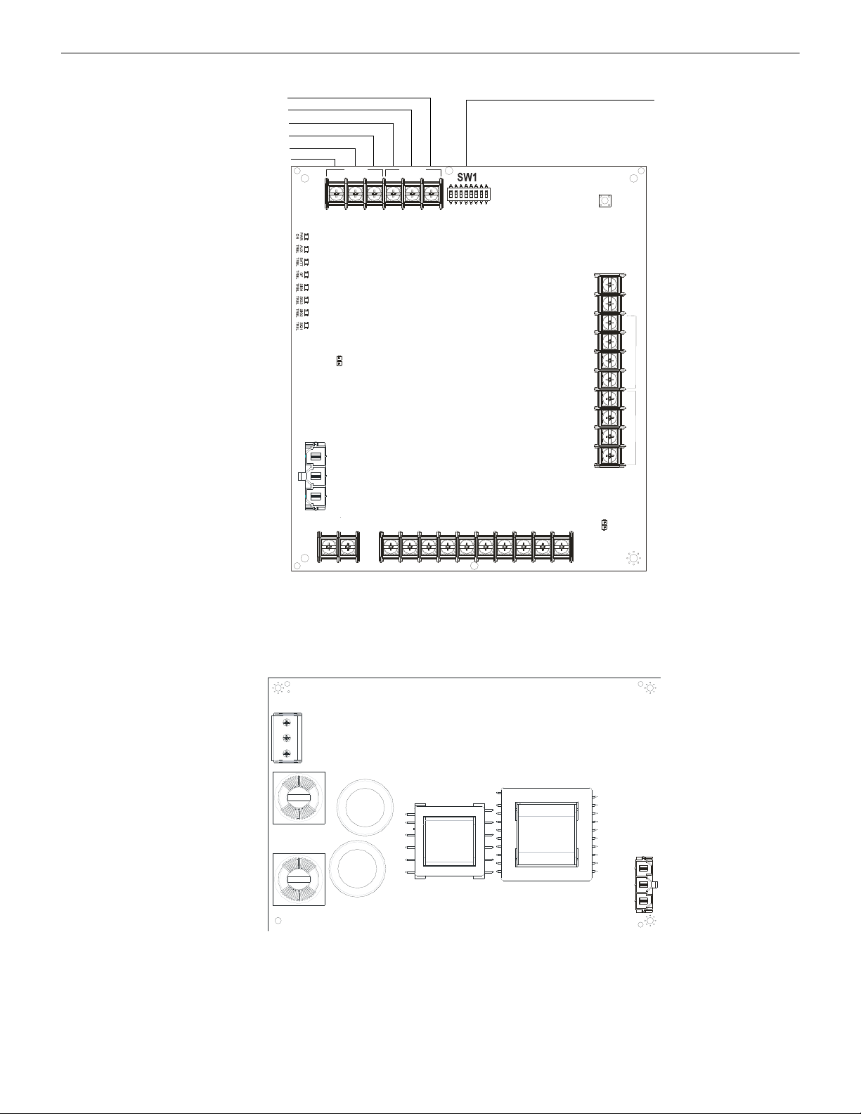
1.4 Jumpers
The HPFF power supplies are comprised internally of two basic components: a 24 VDC power supply and a Control circuit board. The
HPFF12 models have an installed 12.0 A power supply. Jumpers are located on the control circuit board; see Figure 1.1, “Control Circuit
Board”.
8 HPFF12 NAC Expander — P/N 53576:B3 10/1/2018
Page 9

LED Indicators System Overview
TB2
LEDs
N/O
N/C
COMM
N/O
N/C
COMM
AC FAIL
TROUBLE
J1
!
J2
1L2 2L1 2L2
3L1 3L2
4L1 4L2
1.4.1 Charger Disable Jumper (J1)
The HPFF power supplies’ battery charger capacity is 26 AH maximum using the integral
charger with a maximum charging rate of 0.75 A. The integral charger on the Control circuit
board must be disabled in certain situations by removing the charger-disable jumper. One
situation is when system requires a common battery set, as is possible in the large equipment
enclosure. Another situation is if the system requires a larger battery capacity than the integral charger can charge in the proper time. Larger capacity batteries can be used if they are
housed in an external UL-Listed enclosure, along with a UL-Listed battery charger that can
restore the full charge to the batteries in the proper time.
CAUTION: BATTERY CHARGER DISABLE
THE BATTERY CHARGER IS AUTOMATICALLY DISABLED DURING ALARM, SO BATTERIES WILL NOT BE
CHARGED WHEN THE POWER SUPPLY IS IN THE ALARM STAGE.
Larger capacity batteries can be used if they are housed in an external UL-Listed enclosure, along with a UL-Listed battery charger suitable for fire alarm service and with sufficient capacity to restore the full charge in the required time. The alternate enclosure and battery
charger shall be listed for Fire Protective Signaling use.
1.4.2 Ground Fault Disable Jumper (J2)
The Ground Fault detection circuit on the Control circuit board monitors the impedance
from earth ground to any user wiring point, including +24 VDC. An exception is the
initiating device signal inputs because they are optically-isolated from the rest of the
circuitry and should be detected by the initiating device or FACP. Remove ground-fault
disable jumper to disable the ground fault detection.
If the common circuitry of two or more HPFFs are connected together, or if the common of an HPFF is connected to the common of a system, such as a single battery connected to multiple units, then the ground fault jumpers must be removed from all but
one of the units. The unit with the jumper installed provides the ground monitoring for
the whole system. If two or more units are connected together with ground fault monitoring enabled, then the monitoring circuits interfere with each other, and false ground faults will be generated.
1.5 LED Indicators
Indicator Name State Trouble Condition
LED 1, 2, 3, 4 SIG(1, 2, 3, 4) TRBL
LED 5 GF TRBL Steady illumination An earth ground fault is present
LED 6 BAT TRBL
LED 7 AUX TRBL Steady illumination Excessive loading or shorted auxiliary output
LED 8 POWER ON
NOTE: If all four SIG TRBL LEDs are illuminated steady, check if the reference ELR resistor is missing or doesn’t match the ELR resistors
used to terminate the Class B circuits. Otherwise, each NAC must have a trouble.
1.6 Specifications
Refer to Section 1.1, “Control Circuit Board”, on page 11 for terminal locations.
Primary AC Power — TB1 (on 24 VDC power-supply circuit board)
• HPFF12 and HPFF12CM: 120 VAC, 60 Hz, 5.0 A
• HPFF12E and HPFF12CME: 240 VAC, 50 Hz, 2.80 A
• Wire size: 14AWG (2.08 mm²) with 600 V insulation
Initiating Device Signal Inputs — TB3 (on Control circuit board); terminals SIGNAL1: +IN, –IN, +OUT, –OUT, and SIGNAL2:
+IN, –IN, +OUT, –OUT
• Supervised by FACP or initiating device, power-limited
• A supervisory relay must be used if initiating device is a power source.
Blinking NAC Trouble Memory
Steady illumination Open or shorted NAC
Blinking Charger Fault
Steady illumination Low or missing battery
Blinking Low (brown-out) or missing AC input
Steady illumination Normal/Standby
Table 1.1 LED Indicators
HPFF12 NAC Expander — P/N 53576:B3 10/1/2018 9
Page 10

System Overview Specifications
• Available for one of the following:
– 4-wire inputs; or
– 2-wire inputs and an ELR; or
– facilitate multiple unit systems
• Trigger input voltage: 12 and 24 VDC
• Input trigger draw in alarm polarity:
– 12 VDC, 5.68 mA maximum per input
– 24 VDC, 12.26 mA maximum per input
• 12 AWG (3.31 mm²) to 18 AWG (0.821 mm²)
End-of-line Resistor Reference – TB3 (on Control circuit board); terminals REF+ and REF–
• Used for the ELR compare feature
• Range: 1.9K ohms to 25K ohms
• 12 AWG (3.31 mm²) to 22 AWG (0.326 mm²)
NAC Output Circuits — TB4 (on Control circuit board); terminals 1L1(+), 1L2(–), 2L1(+), 2L2(–), 3L1(+), 3L2(–), 4L1(+), and
4L2(–) — alarm polarity in parentheses (See below for other TB4 terminals.)
• Supervised, special application, and power-limited
• Voltage rating: 24 VDC filtered.
• Current:
– Maximum for any one circuit: 3.0 A
– Maximum total continuous for all outputs: HPFF12, HPFF12CM, HPFF12E, HPFF12CME: 12.0 A
• Output circuit types:
– four Class B (Style Y); or
– two Class A (Style Z);
– two Class B (Style Y) and one Class A (Style Z) NACs; or
– four Class A (Style Z) NACs with optional HPP31076 Class A adapter
• 12 AWG (3.31 mm²) to 18 AWG (0.75 mm²)
• Refer to the HPP Device Compatibility Document #54399. for listed compatible devices.
Trouble Contact Rating — TB2 (on Control circuit board); terminals TROUBLE: N/C, COM, and N/O
• Not supervised
• Fail-safe Form-C relay
• Normally energized, transfers with NAC, battery, charger (in standby), AC loss, ground fault, and auxiliary output trouble
• 2.0 A @ 30 VDC
• AC loss trouble can be delayed for 2 hours (see “Programming Options”)
• 12 AWG (3.31 mm²) to 18 AWG (0.75 mm²)
AC Fail Contact Rating — TB2 (on Control circuit board); terminals AC FAIL: N/C, COM, N/O (See above for other TB4 terminals.)
• Not supervised
• Fail-safe Form-C relay
• Normally energized, always transfers with AC loss
• 2.0 A @ 30 VDC
• 12 AWG (3.31 mm²) to 18 AWG (0.75 mm²)
Battery Charging Circuit — TB1 (on Control circuit board); terminals +BATT and –BATT
• Supervised, non-power-limited
• Supports lead-acid type batteries only
• Float charge voltage: 26.6 VDC
• Charger disabled if battery voltage falls below 15 VDC
• Maximum charge current: 0.75 A
• Battery fuse (F1): 15 A, 32 V
• Maximum battery capacity: 26.0 AH
• Minimum battery capacity: 7.0 AH
• Power supply draws a maximum standby current of 75 mA from batteries
Auxiliary Output — TB4 (on Control circuit board); terminals +A and –A (See above for other TB4 terminals.)
• Voltage checked for excessive loading, power limited (PTC), special application
• Voltage rating: 24 VDC continuous (even in alarm)
• Current: 2.0 A maximum. (Subtract auxiliary load from total to determine available NAC load.)
• 12 AWG (3.31 mm²) to 18 AWG (0.75 mm²)
• For a list compatible optional modules that can be connected to the Auxiliary output, see the HPP Device Compatibility Document
#54399.
10 HPFF12 NAC Expander — P/N 53576:B3 10/1/2018
Page 11
Specifications System Overview
TB3
TB4
TB1
TB2
SW2
LEDs
REF+ REF– + IN – IN + OUT – IN + OUT+ OUT + IN – OUT
SIGNAL 1
SIGNAL 2
BATT+ BATT–
A+
N/O
N/C
COMM
N/O
N/C
COMM
AC FAIL
TROUBLE
J1
J2
1L1 1L2 2L1 2L2
3L1 3L2
4L1 4L2A–
REF+
REF–
Signal 1 +IN
Signal 1 –IN
Signal 1 +OUT
Signal 1 –OUT
Signal 2 +IN
Signal 2 –IN
Signal 2 +OUT
Signal 2 –OUT
LEDs:
LED1 (Power On)
LED2 (Auxiliary Trouble)
LED3 (Battery Trouble)
LED4 (Ground Fault Trouble)
LED5 (Signal 4 Trouble)
LED6 (Signal 3 Trouble)
LED7 (Signal 2 Trouble)
LED8 (Signal 1 Trouble)
TB2: AC Fail & Trouble Relays
Trouble N/C
Trouble COMM
Trouble N/O
AC Fail N/C
AC Fail COMM
AC Fail N/O
T
B
1
:
B
a
t
t
e
r
y
+
-
J1: Charger Disable
J2: Ground Fault
Disable
HPFF812PCA2.wmf
S
W
1
(
l
e
f
t
t
o
r
i
g
h
t
)
:
S
I
G
S
E
L
A
C
2
H
R
S
Y
N
S
E
L
‘
B
’
S
Y
N
S
E
L
‘
A
’
S
I
G
3
/
4
‘
B
’
S
I
G
3
/
4
‘
A
’
S
I
G
1
/
2
‘
B
’
S
I
G
1
/
2
‘
A
’
TB3: ELR Reference/
IDC Inputs
Alarm Polarity
Shown
A+ A- 1L1 1L2 2L1 2L2 3L1 3L2 4L1 4L2
TB4: Auxiliary/NAC Outputs
Figure 1.1 Control Circuit Board
SW2: Reset
FF12pca.wmf
Figure 1.2 HPFF12 24 VDC Power Supply Circuit Board
HPFF12 NAC Expander — P/N 53576:B3 10/1/2018 11
Page 12

Notes
12 HPFF12 NAC Expander — P/N 53576:B3 10/1/2018
Page 13
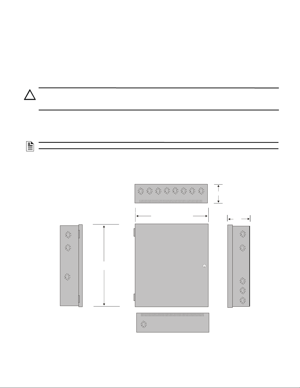
The standard cabinet may be either semi-flush or surface mounted. Fire Alarm Control Panel (FACP) cabinets can only be wall mounted.
!
ff8cab.wmf
Figure 2.1 Standard Cabinet: Dimensions
Door = 19.26” (48.92cm)
Backbox = 19.0” (48.26cm)
Door = 16.821” (42.73cm)
Backbox = 16.65” (42.29cm)
Depth = 5.207” (13.23cm)
Depth =
5.257”
(13.353cm)
Top
Bottom
Left Side Right Side
Each cabinet mounts using two or three key slots and two 0.250" (6.35 mm) diameter holes in the backbox. The key slots are located at
the top of the backbox and the two securing holes at the bottom.
Carefully unpack the system and check for shipping damage. Mount the cabinet in a clean, dry, vibration-free area where extreme temperatures are not encountered. The area should be readily accessible with sufficient room to easily install and maintain the panel. Locate
the top of the cabinet approximately 5 feet (1.5 m) above the floor with hinge mounting on the left. Determine the number of conductors
required for the devices to be installed. Sufficient knockouts are provided for wiring convenience. Select the appropriate knockout(s) and
pull the conductors into the box. All wiring should be in accordance with the National and/or Local codes for fire alarm systems and
power supplies.
2.1 Backbox Mounting
CAUTION: STATIC SENSITIVE COMPONENTS
THE CIRCUIT BOARD CONTAINS STATIC-SENSITIVE COMPONENTS. ALWAYS GROUND YOURSELF WITH A STATIC
STRAP BEFORE HANDLING ANY BOARDS SO THAT THE STATIC CHARGES ARE REMOVED FROM THE BODY. USE
STATIC SUPPRESSIVE PACKAGING TO PROTECT ELECTRONIC ASSEMBLIES.
To prevent damage to the circuit board and to facilitate backbox mounting, the chassis with the 24 VDC power supply and the Control
circuit board can be easily removed. Loosen the two #8-32 nuts securing the top flanges of the chassis, then slide the chassis up to free it
from the lower tabs. Place the chassis assembly in a safe location until it can be reinstalled in the backbox.
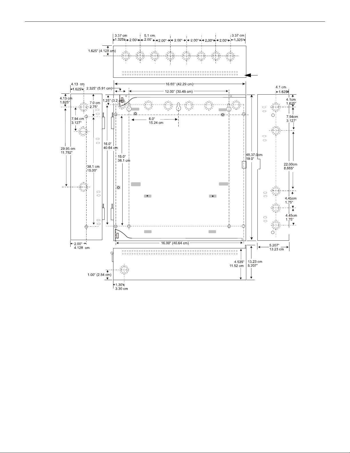
1. Mark and pre-drill a hole in the wall for the center top keyhole mounting bolt using the dimensions illustrated in Figure 2.2 or
Figure 2.3.
NOTE: See the EQ Series Install Sheet PN 53412 for door-mounting details and measurements for B-size and C-size backboxes.
2. Install the center top fastener in the wall with screw head protruding.
3. Place backbox over the top screw, level and secure.
4. Mark and drill the left and right upper and lower mounting holes.
Note: outer holes (closest to sidewall) are used for 16" O.C. stud mounting.
5. Install remaining fasteners.
Section 2: Installation
HPFF12 NAC Expander — P/N 53576:B3 10/1/2018
Page 14
Installation Backbox Mounting
Semi-Flush Mounting
Do not recess box more
than 3.875” into wall to
avoid covering venting
holes on top of box.
92udlsencl.wmf
Figure 2.2 Standard Cabinet: Dimensions for Wall-mounting
14 HPFF12 NAC Expander — P/N 53576:B3 10/1/2018
Page 15

Backbox Mounting Installation
(13.097cm)
5.156”
5.93”
(15.062cm)
5.93”
(15.062cm)
7.12”
(18.084cm)
(6.197cm)
2.44”
0.875” (2.223cm)
1.125” (2.858cm)
45-3/4"
(116.21)
24.125” (61.28cm)
24.0” (60.96cm)
1.625”
(4.13cm)
2.06”
(5.24cm)
11. 5”
(29.21cm)
5.16”
(13.1cm)
(10.16cm)
4”
4”
(5.08cm)
1”
(2.54cm)
11”
(27.94cm)
11”
(27.94cm)
2.625”
(6.604cm)
0.875 (2.22cm)
1.125 (2.86cm)
0.875 (2.22cm)
1.125 (2.86cm)
1.875”
(4.7cm)
37.03”
(94.06cm)
0.31”
(0.79cm)
0.31”
(0.79cm)
45.875”
(116.52cm)
2.25”
(5.72cm)
2.25”
(5.72cm)
19.5”
(49.53cm)
16.0” (40.64cm)
1.125”
(2.858 cm)
0.50”
(1.27 cm)
0.50”
(1.27 cm)
0.250”
(0.635 cm)
HPFF8LargeEqpt.wmf
Chassis-
mounting
studs
(2 per row of
backbox)
Keyholes
2 places
Mounting holes
2 places
e
q
c
a
b
-
d
2
.
w
m
f
Four rows of
Equipment
c
a
b
t
o
p
.
w
m
f
Top View of Backbox
c
a
b
4
k
e
y
h
o
l
e
.
w
m
f
Keyhole dimensions
Height of
mounting bolt
after installation
NOTE: See CAB-4 Series Install Sheet PN 15330 and EQ Series Install Sheet PN 53412 for door-mounting details and
measurements for A, B, and C size backboxes. This drawing shows EQBB-D4 knockout locations.
Top knockout:
Inner:
Outer:
Four Lower knockouts:
Inner:
Outer:
Knockouts:
Inner:
Outer:
Figure 2.3 FACP Cabinet-Mounting Details: Backbox-Mounting Holes and Chassis-Mounting Studs (EQBB-D4
shown)
HPFF12 NAC Expander — P/N 53576:B3 10/1/2018 15
Page 16

Installation Chassis-Mounting in FACP Cabinets
EQ Series Backboxes
(EQBB-D4 shown)
Note: Two-row and three-row mounting is equivalent. Drawings are not to scale.
E
Q
D
c
a
b
i
n
e
t
m
o
u
n
t
i
n
g
h
o
l
e
s
.
w
m
f
Figure 2.4 Chassis-Mounting in FACP Cabinet: Overview
2.2 Chassis-Mounting in FACP Cabinets
Up to three HPFF12CM units can fit into the FACP cabinet. Compatible Fire Alarm Control Panel cabinets include:
Number of Units
Supported
EQ Series Backboxes & Doors
One EQBB-B4 with EQDR-B4 or FCI-VDR-B4B
Two EQBB-C4 with EQDR-C4 or FCI-VDR-C4B
Three EQBB-D4 with EQDR-D4 or FCI-VDR-D4B
Table 2.1 FACP Cabinets
NOTES:
1. When an HPFF12CM unit is mounted in a FACP cabinet, the top row must be left open for proper heat dissipation.
2. Alternate the mounting direction for HPFF12CM as shown in Figure 2.7. Battery must be on left side of bottom row.
See power-limited wiring Section 2.5.2, “Power-Limited Wiring, FACP Cabinet”, on page 27.
Attaching the HPFF12CM onto Mounting Plates
1. Attach power cable to the FFSMTR9-PCA (ships unplugged) as shown in Figure 2.5.
2. Attach mounting plates as shown in Figure 2.6.
3. For the bottom-most chassis-mounting plate only, install four #8-32 keps nuts on the plate’s studs as shown in Figure 2.6. This will
properly space the battery well away from the backbox’s mounting hardware.
4. Align HPFF12CM module with the backbox’s mounting studs; fasten securely using four #8-32 keps nuts as shown in Figure 2.7.
5. Install battery well by resting the bottom on top of the studs and securing the top with two #8-32 keps nuts as shown in Figure 2.7.
16 HPFF12 NAC Expander — P/N 53576:B3 10/1/2018
Page 17

Chassis-Mounting in FACP Cabinets Installation
h
p
f
f
1
2
c
m
-
c
a
b
l
e
.
w
m
f
Attach plug to
transformer.
(Ships unplugged.)
Figure 2.5 Attaching Transformer Plug
Note: Components have been
removed from this graphic for
illustration purposes only.
hpff12cm-plate-mtg.wmf, hpff12cm-bottom-
Attach each chassis-
mounting plate to
backbox with two
#8-32 kep nuts.
For the bottom chassis-mounting plate only:
Install four #8-32 kep nuts onto studs
where battery well is to be located.
NOTE: This can be done before or after
attaching chassis-mounting plate to backbox.
Note: Two-row and three-row mounting is equivalent.
Figure 2.6 Installing Chassis-Mounting Plates onto Backbox (EQBB-D4 Shown)
HPFF12 NAC Expander — P/N 53576:B3 10/1/2018 17
Page 18

Installation Chassis-Mounting in FACP Cabinets
h
p
f
f
1
2
c
m
m
n
t
-
e
q
d
s
i
z
e
.
w
m
f
Do not mount
HPFF12CM
in top row.
The HPFF12CM
chassis-mounting
direction must be
alternated for proper
heat dissipation.
Battery must be on left
side of bottom row.
Attach
HPFF12CM
module with four
#8-32 keps nuts.
Secure top of
battery well with
two #8-32 keps nuts.
Figure 2.7 HPFF12CM: Chassis-Mounting in Backbox
(EQBB-D4 Shown)
18 HPFF12 NAC Expander — P/N 53576:B3 10/1/2018
See power-limited wiring “HPFF12CM(E) Power-Limited Wiring, EQBB-D4 Backbox” on page 27.
Page 19

Chassis-Mounting in FACP Cabinets Installation
Figure 2.8 Two HPFF12CM Modules in an
EQBB-C4 Backbox
h
p
f
f
1
2
c
m
m
n
t
-
e
q
c
s
i
z
e
.
w
m
f
Figure 2.9 One HPFF12CM Module in an
EQBB-B4 Backbox
h
p
f
f
1
2
c
m
m
n
t
-
e
q
c
s
i
z
e
.
w
m
f
See power-limited wiring “HPFF12CM(E) Power-Limited Wiring, EQBB-D4 Backbox” on page 27.
HPFF12 NAC Expander — P/N 53576:B3 10/1/2018 19
Page 20

Installation NAC Circuit Wiring
TB4TB1
TB2
LEDs
REF+ REF– + IN – IN
+ OUT
– IN
+ OUT+ OUT
+ IN
– OUT
SIGNAL 1
SIGNAL 2
BATT+ BATT–
A+
N/O
N/C
COMM
N/O
N/C
COMM
AC FAIL
TROUBLE
1L1 1L2 2L1 2L2
3L1 3L2
4L1 4L2A–
+
-
+
-
+
-
+
-
-
+
-
+
-
+
-
+
Reference Resistor
H
P
F
F
1
2
N
A
C
C
l
a
s
s
B
.
w
m
f
Horn Strobe
Horn Strobe
Horn Strobe
EOL same as
Reference Resistor
Alarm Polarity Shown
• Trouble on NAC1
will illuminate
LED1 SIG1 TRBL.
• Trouble on NAC2
will illuminate
LED2 SIG2 TRBL.
• Trouble on NAC3
will illuminate
LED3 SIG3 TRBL.
• Trouble on NAC4
will illuminate
LED4 SIG4 TRBL.
NAC 4
NAC 3
NACs 1 - 3 are wired the same as NAC4 and use
an ELR which is the same as Reference Resistor.
NAC 1 NAC 2
Figure 2.10 Four NACs in Class B (Style Y)
2.3 NAC Circuit Wiring
For wiring sizes, see Section 6.5, “NAC Circuit Loop Wiring Requirements”.
2.3.1 Four NACs Configured for Class B (Style Y)
Figure 2.10 shows four NACs configured for Class B (Style Y).
NOTES:
1. Typical ELRs for new installations can be 3.9k or 4.7k ohm.
2. The same gauge wire must be used if two conductors are connected to the same terminal of any terminal block.
3. Do not complete a continuous circuit around the screw terminal. There must be two separate wires on either side of the screw at the
terminal block. “T-tapping” is absolutely NOT ALLOWED.
20 HPFF12 NAC Expander — P/N 53576:B3 10/1/2018
Page 21

NAC Circuit Wiring Installation
+
-
+
-
+
-
+
-
TB3
TB4TB1
TB2
LEDs
REF+ REF– + IN – IN
+ OUT
– IN
+ OUT+ OUT
+ IN
– OUT
SIGNAL 1
SIGNAL 2
BATT+ BATT–
A+
N/O
N/C
COMM
N/O
N/C
COMM
AC FAIL
TROUBLE
1L1 1L2 2L1 2L2
3L1 3L2
4L1 4L2A–
-
+
-
+
-
+
-
+
NAC 2
H
P
F
F
1
2
N
A
C
C
l
a
s
s
A
.
w
m
f
Horn Strobe
Horn Strobe
Horn Strobe
Alarm Polarity
Shown
• Trouble on NAC1
will illuminate
LED1 SIG1 TRBL and
LED2 SIG2 TRBL
• Trouble on NAC2
will illuminate
LED3 SIG3 TRBL
and LED4 SIG4 TRBL
Note: NAC 2 in Class A;
no ELR required.
Note: NAC 1 Class A
wired same as NAC2.
NAC 1
Figure 2.11 Two NACs in Class A (Style Z)
2.3.2 Two NACs Configured for Class A (Style Z)
Figure 2.11 shows two NACs configured for Class A (Style Z).
NOTES:
1. Typical ELRs for new installations can be 3.9k or 4.7k ohm.
2. The same gauge wire must be used if two conductors are connected to the same terminal of any terminal block.
3. Do not complete a continuous circuit around the screw terminal. There must be two separate wires on either side of the screw at the
terminal block. “T-tapping” is absolutely NOT ALLOWED.
HPFF12 NAC Expander — P/N 53576:B3 10/1/2018 21
Page 22

Installation NAC Circuit Wiring
+
-
+-+-+
-
NOTE: NAC 1 and NAC 2 in
Class B (Style Y) - See
Section 2.3.1 for wiring.
NAC 3
H
P
F
F
1
2
N
A
C
C
l
a
s
s
A
w
i
t
h
B
.
w
m
f
Horn Strobe
Horn Strobe
Horn Strobe
Alarm Polarity
Shown
Note: NAC 3 in Class A;
no ELR required.
NAC 1
• Trouble on NAC1
will illuminate
LED1 SIG1 TRBL
• Trouble on NAC2
will illuminate
LED2 SIG2 TRBL
• Trouble on NAC3
will illuminate
LED3 SIG3 TRBL and
LED4 SIG4 TRBL
Reference Resistor
(Same as ELRs for
NAC 1 & NAC2)
NAC 2
Figure 2.12 Configuring Two Class B NACs and One Class A NAC on One HPFF
2.3.3 Mixing Class B and Class A NACs
Figure 2.12 shows two NACs configured for Class B (Style Y) and one NAC configured for
Class A (Style Z).
NOTES:
1. Typical ELRs for new installations can be 3.9k or 4.7k ohm.
2. The same gauge wire must be used if two conductors are connected to the same terminal of any terminal block.
3. Do not complete a continuous circuit around the screw terminal. There must be two separate wires on either side of the screw at the
terminal block. “T-tapping” is absolutely NOT ALLOWED.
22 HPFF12 NAC Expander — P/N 53576:B3 10/1/2018
Page 23

Mounting Addressable Modules Installation
TB4TB1
TB2
LEDs
REF+ REF– + IN – IN
+ OUT
– IN
+ OUT+ OUT
+ IN
– OUT
SIGNAL 1
SIGNAL 2
BATT+ BATT–
A+
N/O
N/C
COMM
N/O
N/C
COMM
AC FAIL
TROUBLE
1L1 1L2 2L1 2L2
3L1 3L2
4L1 4L2A–
-
+
-
+
-
+
-
+
}
NAC4
NAC Return
}
}
}
}
NAC3NAC2NAC1
– +– +– + – +
NAC Out
}
H
P
F
F
1
2
-
H
P
P
3
1
0
7
6
-
N
A
C
s
.
w
m
f
Reference Resistor
3.9K ohm is required
for the Class A adapter
Alarm Polarity
Shown
• Trouble on NAC1
will illuminate
LED1 SIG1 TRBL
• Trouble on NAC2
will illuminate
LED2 SIG2 TRBL
• Trouble on NAC3
will illuminate
LED3 SIG3 TRBL
• Trouble on NAC4
will illuminate
LED4 SIG4 TRBL
Note: ELR is not required, but
the 3.9kohm reference resistor
is required.
NACs 1 - 3 are wired the same
as NAC4.
Note: Use wire gauge from
12AWG-18AWG.
Figure 2.13 Four Class A (Style Z) NACs with HPP31076 Adapter
2.3.4 HPP31076 Optional Class A (Style Z) Adapter
The HPP31076 is an optional adapter to connect four Class A (Style Z) NAC circuits. It mounts directly onto the terminal block TB4 of
the Control circuit board. The adapter kit includes two plastic standoffs to provide support. The same gauge wire must be used if two
conductors are connected to the same terminal of any terminal block.
NOTE: Only use batteries with a maximum height of 4 inches in applications that require this adapter in the standard enclosure.
Otherwise, there is insufficient space to connect NAC field wiring, and a separate NFPA and UL 864 rated enclosure is required.
2.4 Mounting Addressable Modules
NOTES:
1. Typical ELRs for new installations can be 3.9k or 4.7k ohm.
2. The same gauge wire must be used if two conductors are connected to the same terminal of any terminal block.
3. Do not complete a continuous circuit around the screw terminal. There must be two separate wires on either side of the screw at the
terminal block. “T-tapping” is absolutely NOT ALLOWED.
The HPFF12 and the HPFF12E are designed to mount Honeywell Fire Systems addressable control or relay modules on the Control circuit board inside the power supply cabinet. This allows power to be fed from the Auxiliary output directly to the module, if needed, without running the power wires outside the cabinet. For a list of compatible optional modules that can be connected to the Auxiliary output,
see the HPP Device Compatibility Document. Two single output modules may be mounted directly above each other if required by applications such as Split Alarm or Selective Silence. Alternately, two outputs of a 6-output addressable module can also be used and
mounted on the Control board.
HPFF12 NAC Expander — P/N 53576:B3 10/1/2018 23
Page 24

Installation Mounting Addressable Modules
H
P
F
F
1
2
m
n
t
c
m
f
.
w
m
f
Standoff Standoff
Standoff
Standoff
Figure 2.14 Mounting Details for Control & Relay Modules from Honeywell Fire Systems
2.4.1 Mounting Modules from Honeywell Fire Systems
Addressable modules can be mounted directly to the Control circuit board as shown in Figure 2.14 for the wall cabinet. This allows wiring to remain in the cabinet. Two modules can be mounted on top of each other if the application requires two independent inputs, such
as silencing. Alternately, two outputs of a six-output addressable module can also be used. The six-output module can also be mounted
directly on the Control board.
Mounting addressable modules on the Control circuit board is also possible in the HPFF12CM(E) units. However, the six-output module
must be mounted in an optional multi-module chassis if used in the large cabinet enclosure.
See Section 2.5, “Power-Limited Wiring Requirements”.
24 HPFF12 NAC Expander — P/N 53576:B3 10/1/2018
Page 25

Power-Limited Wiring Requirements Installation
H
P
F
F
1
2
m
n
t
6
u
p
.
w
m
f
Figure 2.15 Mounting Details for Six-Output Modules from Honeywell Fire Systems
Standoff
Standoff
Standoff
Standoff
2.4.2 Mounting Six-Circuit Modules from Honeywell Fire Systems
Six-output addressable modules can be mounted directly to the control circuit board as shown in Figure 2.15 for the wall cabinet. This
allows wiring to remain in the cabinet. However, the six-output module cannot be mounted as shown in the HPFF12CM(E) units when
used in the large equipment enclosure. An optional multi-module chassis is available from Honeywell Fire Systems.
See Section 2.5, “Power-Limited Wiring Requirements”.
2.5 Power-Limited Wiring Requirements
Power-limited and non-power-limited circuit wiring must remain separated in the cabinet. All power-limited wiring must remain at least
0.25" away from any non-power-limited circuit wiring. Furthermore, all power-limited circuit wiring and non-power-limited circuit wiring must enter and exit the cabinet through different conduits. An example of this is shown below. Your specific application may require
different conduit knockouts to be used in the standard cabinet. Any conduit knockouts may be used. For power-limited applications, use
of conduit is optional.
HPFF12 NAC Expander — P/N 53576:B3 10/1/2018 25
Page 26

Installation Power-Limited Wiring Requirements
TB3
TB4TB1
TB2
LEDs
REF+ R EF– + IN – IN
+ OUT
– IN
+ OUT+ OUT
+ IN
– OUT
SIGNAL 1
SIGNAL 2
BATT+ BATT–
A+
N/O
N/C
COMM
N/O
N/C
COMM
AC FAIL
TROUBLE
1L1 1L2 2L1 2L2 3L1 3L2 4L1 4L2A–
Input Circuits
Power-limited
Specific Application:
Power & SLC are
power-limited
Output Circuits
Power-limited
AC Circuits
Nonpower-limited
Relay Contacts
Nonpower-limited
H
P
F
F
8
1
2
m
n
t
p
w
r
l
i
m
.
w
m
f
Battery connections
Nonpower-limited
Figure 2.16 Power-Limited Wiring Example:
HPFF12(CM)(E) Shown with Single-input Control Module
Input Circuits
Power-limited
Specific Application:
Power & SLC are
power-limited
Output Circuits
Power-limited
AC Circuits
Non-power-limited
Relay Contacts
Nonpower-limited
H
P
F
F
1
2
m
n
t
p
w
r
l
i
m
6
u
p
.
w
m
f
Battery connections
Nonpower-limited
Maintain vertical
separation where
power-limited and
non-power-limited
circuits appear
close together.
Figure 2.17 Power-Limited Wiring Example:
HPFF12(E) Shown with Multi-module
2.5.1 Power-Limited Wiring, Standard Chassis
26 HPFF12 NAC Expander — P/N 53576:B3 10/1/2018
Page 27

Power-Limited Wiring Requirements Installation
– +
– +
– + – +
Knockout for
Power-limited wiring
Output circuits and
Auxiliary Output:
Power-limited
Battery connections:
Non-power-limited
Relay Contacts:
Non-power-limited
Knockout for
Non-power-limited
wiring
Knockout for
Power-limited wiring
AC Power:
Non-power-limited
(See Figure 2.19 for
wiring detail.)
Maintain 0.25" in. vertical
separation where
power-limited and
non-power-limited circuits
appear to “cross”
Figure 2.18 Power-Limited Wiring Example: EQBB-D4 with HPFF12CM(E)
Input Circuits:
Power-limited
Output circuits and
Auxiliary Output:
Power-limited
Knockout for
Non-power-limited
wiring
2.5.2 Power-Limited Wiring, FACP Cabinet
HPFF12CM(E) Power-Limited Wiring, EQBB-D4 Backbox
HPFF12 NAC Expander — P/N 53576:B3 10/1/2018 27
Page 28

Installation Power-Limited Wiring Requirements
Ground Stud
TB1 on 24 VDC circuit board
L1
Ground
L2
Ground Stud
Wire Nut
Line Neutral Ground
Ring Terminal
Figure 2.19 Power-Limited Wiring Example: EQBB-D4 AC Wiring (Expanded)
28 HPFF12 NAC Expander — P/N 53576:B3 10/1/2018
Page 29

This section describes the programming options available via DIP switch settings. The HPFF can be field-programmed using DIP switch
Switches 2-7
shown in OFF position
Switch 1
shown in ON position
H
P
F
F
8
1
2
-
s
w
1
.
w
m
f
Figure 3.1 Field-Programming DIP Switches
SW1 on the Control circuit board. Refer to the following illustration for switch location and DIP switch settings for ON and OFF positions.
3.1 DIP Switch Settings
The following table lists the programmable features and the switch settings required to select a particular feature. A detailed description
of each is presented in the following pages.
1 SIG 1/2 “A”
2 SIG 1/2 “A”
3 SIG 3/4 “B”
4 SIG 3/4 “B”
5 SYN SEL “B”
6 SYN SEL “A”
7 AC 2HR OFF - No delay in Trouble reporting with an AC failure.
8 SIG SEL This switch works in conjunction with the initiating device signal input(s) and switches 1 through 6 to
1 OFF, 2 OFF = Pass-through (of Steady On, sync, or coded; DO NOT use with full-wave rectified input).
1 ON, 2 OFF = Temporal.
1 OFF, 2 ON = Sync generator (see switches 5 & 6).
1 ON, 2 ON = Pass-through Filtered (use for full-wave rectified inputs).
3 OFF, 4 OFF = Pass-through (of Steady On, sync, or coded; DO NOT use with full-wave rectified input).
3 ON, 4 OFF = Temporal.
3 OFF, 4 ON = Sync generator (see switches 5 & 6).
3 ON, 4 ON = Pass-through Filtered (use for full-wave rectified inputs).
5 OFF, 6 OFF = Cooper Wheelock
5 ON, 6 OFF = System Sensor
5 OFF, 6 ON = Amseco and Faraday
5 ON, 6 ON = Gentex
ON - 2 hour delay in Trouble reporting with an AC failure.
See Sections 3.2.3 and 3.2.4 for further details of TB2 immediate AC Fail and programmed no delay/delayed
Trouble contacts.
determine General Alarm*, Split Alarm**, or Silencing***.
8 ON = Split Alarm**
8 OFF, Signal Input 1 ON, Signal Input 2 ON = General Alarm* on all four NAC outputs.
8 OFF, Signal Input 1 ON, Signal Input 2 OFF = Silencing*** of all four NAC outputs.
*General Alarm is visual strobe and audible horn activation.
**Split Alarm is Signal Input I controlling NAC outputs 1 and 2, and Signal Input 2 controlling NAC outputs 3
and 4.
***Silencing is visual strobe activation but audible horn is silenced for the initiating device.
Section 3: Programming Options
SW1 DIP Switch
• NAC outputs 1 and 2 are controlled by Signal Input 1.
• NAC outputs 3 and 4 are controlled by Signal Input 2.
Table 3.1 DIP Switch Settings
HPFF12 NAC Expander — P/N 53576:B3 10/1/2018
Page 30

Programming Options Programmable Features
3.2 Programmable Features
3.2.1 Input/Output Functions
DIP switches 1 through 4 are used to determine the input to output functions of the HPFF power supplies. The NAC outputs are programmed in pairs. DIP switches 1 and 2 are used to determine the input to output functions for NAC outputs 1 and 2. DIP switches 3 and
4 are used determine the input to output functions for NAC outputs 3 and 4.
NAC Outputs 1 & 2
DIP Switch 1 DIP Switch 2 Function
OFF OFF Pass-through (of Steady On, sync, or audible coded; DO NOT use with full-wave rectified input).
ON OFF Temporal generator.
OFF ON Sync generator (see Synchronization Type below).
ON ON Pass-through Filtered (use for full-wave rectified inputs).
Table 3.2 Input/Output Configurations for NACs 1 & 2
NAC Outputs 3 & 4
DIP Switch 3 DIP Switch 4 Function
OFF OFF
ON OFF
OFF ON
ON ON
The pass-through feature passes any signal on the initiating device inputs to the NAC outputs. These signal inputs are independent in
pass-through, so visual sync protocol and audible coded signals may be passed simultaneously. The signal types may include steady-on,
march time, temporal or audible coded signals.
The temporal generator feature is used to have the power supply generate a temporal audible code.
The filtered feature is used to provide a steady-on output with full-wave rectified unfiltered input, and can be used to reduce or eliminate
spurious outputs that are caused by noise on the inputs.
Pass-through (of Steady On, sync, or audible coded; DO NOT use with full-wave rectified input).
Temporal generator.
Sync generator (see Synchronization Type below).
Pass-through Filtered (use for full-wave rectified inputs).
Table 3.3 Input/Output Configurations for NACs 3 & 4
3.2.2 Synchronization Type
Synchronization is a feature that controls the activation of notification appliances in such a way that all devices turn on and off at exactly
the same time. Unsynchronized strobe activation can be a potential hazard and can cause confusion. The HPFF power supplies can be
programmed to operate with a variety of manufacturers’ devices.
DIP switches 5 and 6 are used to select the synchronization type when switches 1 & 2 and 3 & 4 are programmed for the power supply to
be a sync generator.
DIP Switch 5 DIP Switch 6 Synchronization Type
OFF OFF
ON OFF
OFF ON
ON ON
Cooper Wheelock devices
System Sensor devices
Amseco and Faraday devices
Gentex devices
Table 3.4 Synchronization Type for DIP Switches 5 and 6
3.2.3 Trouble Reporting Delay with an AC Failure
There are three ways to report trouble of AC loss or brownout. The transfer of TB2's AC FAIL contacts, TB2's TROUBLE contacts, and
the opening of the FACP or initiating device SIGNAL 1’s and SIGNAL 2’s connections on TB3.
Both SIGNAL 1’s and SIGNAL 2’s +IN to +OUT connections are opened to disconnect Class B ELR’s or the positive wire run of Class
A configuration. They remain closed in the alarm state, even if a trouble condition exists, to pass the alarm signal if multiple units are
connected. Therefore, supervised monitoring TB2's AC FAIL and TROUBLE contacts is necessary for UL 864 9th Edition compliance.
• DIP switch 7 set to the ON position will delay the transfer of the TB2's TROUBLE contacts and the opening of connections on TB3
for 2 hours (unless in alarm state), upon an AC loss or brownout.
• DIP switch 7 set to the OFF position will have no delay in the transfer of the TB2's TROUBLE contacts and the opening of ELR
connections on TB3 (unless in alarm state), upon an AC loss or brownout.
TB2's AC FAIL contacts will always immediately transfer if an AC loss or brownout occurs, regardless of DIP switch 7 setting. These
contacts can be used for local reporting to the protected premises, in compliance with UL 864 9th Edition.
30 HPFF12 NAC Expander — P/N 53576:B3 10/1/2018
Page 31

Programmable Features Programming Options
The DIP switch 7 setting of a 2 hour delay of TB2 TROUBLE contacts can be used for remote station, central station, or proprietary protected premises reporting, in compliance with UL 864 9th Edition.
NOTE: Always use supervised monitoring of TB2’s AC FAIL and TROUBLE contacts and to set DIP switch 7 for a delay for UL 864 9th
Edition compliance.
3.2.4 Split Alarm and Silencing
DIP switch 8, in conjunction with initiating device signal inputs and DIP switches 1 through 6, is used to program the features of General
Alarm, Split Alarm, or Silencing.
• DIP switch 8 set to the ON position will split the NAC outputs to pairs. NAC outputs 1 & 2 are controlled by Signal Input 1 and
NAC outputs 3 & 4 are controlled by Signal Input 2. The output pairs will be selectively silenced if DIP switches 1 through 6 are set
for Pass-through and FACP input is wired and programmed for that operation.
• DIP switch 8 set to the OFF position and at least one of the NAC outputs are programmed for synchronization, Signal Input 1 & 2
ON will generate a General Alarm on all four NAC outputs. General Alarm is activation of both visual strobe and audible horns.
• DIP switch 8 set to the OFF position and at least one of the NAC outputs are programmed for synchronization, Signal Input 1 ON
and Signal Input 1 OFF will silence all four NAC outputs while keeping visual strobe activation.
NOTE: See Section 5.1 and 5.2 for proper alarm input wiring when DIP switch 8 is programmed in the OFF position.
HPFF12 NAC Expander — P/N 53576:B3 10/1/2018 31
Page 32

Section 4: Trouble Supervision
4.1 Supervised Functions and Field Wiring
• Field-wiring fault (short or open) on the NAC outputs of the power supply
• AC failure or brownout at the power supply
• Battery failure (no battery or battery voltage less than 20.5 VDC) condition at the power supply
• Battery charger failure on the power supply
• Ground fault condition
• +/- Reference Resistor
NOTE: The trouble contacts AC FAIL and TROUBLE on TB2 and initiating device inputs SIGNAL1 and SIGNAL2 on TB3 are not
supervised by the HPFF12, but are used for supervision of the HPFF12 by the FACP.
4.2 Trouble Reporting
4.2.1 Normal/Standby
Normal / Standby Trouble contacts
Fault
Present (Note
Field Wiring (NAC
& +/-REF)
Battery No Battery or <20.5 VDC (Note
Battery Charger
Auxiliary output Excessive load or short (Note
AC
1. No transfer and COMM & N/C are shorted.
2. The shorted contacts of COMM & N/C transfer to COM & N/O.
3. A battery fail indication can also occur if there was an AC failure within the first 24 hours after initial power-up and the battery voltage had been
discharged to a voltage between 20.5- 26.5 VDC. The BATT TRBL battery trouble LED may illuminate steady, after a certain delay during
charging, to indicate the battery was discharged and may not support a full alarm load. The delay is based on operational conditions (time
remaining in the first 24 hours, time in stand-by, and time in alarm) and will extinguish if the battery charging has time to reach its float voltage.
Short or
Open
Ground Fault (Note
Battery not reach float
Loss or
Brownout
Past
(Trouble
Memory)
Fault (Note
3
)
(Note
No Delay
Delay
TB2: AC
FAIL
1
1
(Note
1
1
1
1
(Note
1
immediate
transfer
immediate
transfer
TB2:
TROUBLE
)(Note 2) open
)(Note 1)closed
)(Note 1) open LED5: GF TRBL Steady illumination Auto
)(Note 2) open LED6: BATT TRBL Steady illumination Auto
)(Note 2) open LED6: BATT TRBL Blink Auto
)(Note 2) open LED6: BATT TRBL Steady illumination Auto
)(Note 2) open LED7: AUX TRBL Steady illumination Auto
no delay
transfer
2hr delayed
transfer
TB3: +IN &
+OUT
no delay
open
2hr delayed
open
LED Reset?
LED1: SIG1 TRBL Steady illumination Auto
LED2: SIG2 TRBL Steady illumination Auto
LED3: SIG3 TRBL Steady illumination Auto
LED4: SIG4 TRBL Steady illumination Auto
LED1: SIG1 TRBL Blink
LED2: SIG2 TRBL Blink
LED3: SIG3 TRBL Blink
LED4: SIG4 TRBL Blink
LED8: PWR ON Blink Auto
LED8: PWR ON t Blink Auto
SW1 or
Power cycle
SW1 or
Power cycle
SW1 or
Power cycle
SW1 or
Power cycle
32 HPFF12 NAC Expander — P/N 53576:B3 10/1/2018
Page 33

Trouble Reporting Trouble Supervision
4.2.2 Alarm
Alarm Trouble contacts
Fault
Excessive
Field Wiring
(NAC & +/- REF)
Battery No battery or <20.5 VDC (Note
Battery Charger
Auxiliary Output Excessive load or short (Note
AC
1. No transfer and COMM & N/C are shorted.
2. The shorted contacts of COMM & N/C transfer to COM & N/O.
3. A battery fail indication can also occur if there was an AC failure within the first 24 hours after initial power-up and the battery voltage had been
discharged to a voltage between 20.5- 26.5 VDC. The BATT TRBL battery trouble LED may illuminate steady, after a certain delay during
charging, to indicate the battery was discharged and may not support a full alarm load. The delay is based on operational conditions (time
remaining in the first 24 hours, time in stand-by, and time in alarm) and will extinguish if the battery charging has time to reach its float voltage.
4. Battery Charger disabled during alarm.
Short or
Open
Battery not reach float
Loss or
Brownout
Load (Two
re-tries of
>4 Amps)
Ground Fault (Note
Fault (Note
3
)
(Note
No Delay
Delay
TB2: AC
Fail
1
(Note
1
1
1
1
(Note
1
Immediate
transfer
Immediate
transfer
TB2:
TROUBLE
)(Note 2)closed
)(Note 2) closed LED5: GF TRBL Steady Illumination Auto
)(Note 1) closed LED6: BATT TRBL (Note 4)(Note
)(Note 1) closed LED6: BATT TRBL (Note 4)(Note
)(Note 1) closed LED6: BATT TRBL (Note 4)(Note
)(Note 1) closed LED7: AUX TRBL Steady Illumination Auto
No delay
transfer
2hr delayed
transfer
TB3: +IN &
+OUT
LED1: SIG1 TRBL Steady Illumination
LED2: SIG2 TRBL Steady Illumination
LED3: SIG3 TRBL Steady Illumination
LED4: SIG4 TRBL Steady Illumination
closed LED8: PWR ON Blink Auto
closed LED8: PWR ON Blink Auto
LED Reset?
Power cycle
Power cycle
Power cycle
Power cycle
SW1 or
SW1 or
SW1 or
SW1 or
4
)
4
)
4
)
4.2.3 TB2: AC FAIL Contacts
TB2’s AC FAIL contacts are not supervised by the HPFF power supply, but will be supervised by the FACP. The normally shorted
COMM and N/C contacts will transfer to the COMM and N/O contacts being shorted, only when an AC failure occurs. The transfer
always occurs immediately
reporting of an AC failure for compliance of UL 864 9
and will not be delayed even if DIP switch 7 is in the ON position. These contacts should be used for local
th
Edition.
4.2.4 TB2: TROUBLE Contacts
TB2’s TROUBLE contacts are not supervised by the HPFF power supply, but will be supervised by the FACP. The normally shorted
COMM and N/C contacts will transfer to the COMM and N/O contacts being shorted when a fault condition occurs. The transfer will not
be delayed except if the fault is an AC failure and DIP switch 7 is in the ON position. The transfer will be delayed for 2 hours in this
case. These contacts should be used for delayed remote reporting of an AC failure for compliance of UL 864 9
4.2.5 TB3: Initiating Device Inputs SIGNAL 1 and SIGNAL 2
TB3’s alarm SIGNAL 1 and SIGNAL 2 inputs are not supervised by the HPFF power supply. They will be supervised by the FACP or
initiating device. The four connections +IN, –IN, +OUT, and –OUT are used to connect either from a two-wire/Class B (Style Y) NAC
with an end-of-line resistor (ELR) or a four-wire/Class A (Style Z) NAC.
Both SIGNAL 1’s and SIGNAL 2’s +IN to +OUT connections are opened to disconnect Class B ELR’s or the positive connection of
Class A input. However, they will always remain closed* in the alarm state, even if a trouble condition exists. The alarm signal will then
be passed if multiple units are connected.
NOTE: *TB3's SIGNAL 1 and SIGNAL 2 connections remain closed in the alarm state. Always use supervised monitoring of TB2's
TROUBLE and AC FAIL contacts to annunciate troubles at the FACP.
4.2.6 Trouble Memory
The HPFF has NAC Trouble Memory by storing the NAC output number(s) when a trouble has been experienced. The unit will then
blink the corresponding yellow SIGTRBL LED(s) when all the troubles are cleared. This helps the installer or repair personnel to find
the cause of intermittent troubles.
The NAC Trouble Memory is permanently latched. To clear it, the AC must be cycled and the battery momentarily disconnected, or just
press SW2 (microprocessor reset) on the control PCB.
If the panel is in alarm, an excessively loaded or shorted NAC is only trouble condition that will cause the Trouble contacts to transfer.
th
Edition.
HPFF12 NAC Expander — P/N 53576:B3 10/1/2018 33
Page 34

Trouble Supervision Trouble Reporting
If the current in any NAC exceeds 3.5 A due to excessive loading, the unit disables its output for approximately 8 seconds. The unit will
then attempt to re-engage the NAC output(s), and will disable it if the 3.5 A is exceeded again. If an overload condition exceeding 4.0 A
exists for more than two re-engagements, the unit will illuminate the corresponding yellow SIG TRBL LED(s) steady and generate a
general trouble. This is a latched overload condition, but the unit will keep attempting to re-engage the NAC output. The general trouble
transfers only the Trouble contact until the alarm condition clears.
4.2.7 Ground Fault Detection
A ground fault trouble will be generated if there is 50 K ohms or lower between Earth Ground and the field wiring, except the initiating
device SIGNAL 1 and SIGNAL2 inputs and TB2 AC FAIL and TROUBLE contacts. The signal inputs are optically-isolated from the
HPFF’s circuitry and will be supervised by the FACP. TB2’s contacts are dry contacts and will be supervised by the FACP.
4.2.8 NAC Overload Protection and Indication
If the current in any NAC exceeds the 3.5 A maximum, the unit disables its output for approximately 8 seconds. The unit will then
attempt to re-engage the NAC output(s), and will disable it if the 3.5 A is exceeded again. If an overload condition exceeding 4.0 A
exists for more than two re-engagements, the unit will illuminate the corresponding yellow SIG TRBL LED(s) steady and transfer the
TB2’s TROUBLE contacts. This is a latched overload condition, but the unit will keep attempting to re-engage the NAC output while in
alarm.
To clear the permanently latched overload condition, the AC must be cycled and the battery momentarily disconnected, or just press
SW2 (microprocessor reset) on the Control circuit board.
34 HPFF12 NAC Expander — P/N 53576:B3 10/1/2018
Page 35

Section 5: Applications
TB3
TB4TB1
TB2
SW2
LEDs
REF+ REF– + IN – IN + OUT – IN + OUT+ OUT + IN – OUT
SIGNAL 1
SIGNAL 2
BATT+ BATT–
A+
N/O
N/C
COMM
N/O
N/C
COMM
AC FAIL
TROUBLE
J1
J2
1L1 1L2 2L1 2L2
3L1 3L2
4L1 4L2A–
+
-
Alarm Polarity
Shown
NAC Output
from FACP
Ref +
Ref -
In #1 +
In #1 -
Out #1 +
Out #1 -
In #2 +
In #2 -
Out #2 +
Out #2 -
ELR
Ref
Figure 5.1 Controlling Four NAC Circuits from a Single Source
5.1 Controlling Four NAC Circuits from a Single Source
In this application, all four NACs (Notification Appliance Circuits) are controlled by single input from a FACP (Fire Alarm Control
Panel) as illustrated in Figure 5.1. The FACP could be replaced by a supervised addressable control module associated with a fire alarm
control panel.
If the Programming DIP Switches are set as shown below, all four NACs will follow (Pass-through) the signal from the FACP.
SW1-8
OFF
SW1-7
N/A
SW1-6
OFF
SW1-5
OFF
SW1-4
OFF
SW1-3
OFF
SW1-2
OFF
SW1-1
All four NAC outputs will follow FACP output. FACP output can be steady on, coded, temporal, sync, etc.
OFF
Notes for Figure 5.1:
1. When the power supply is in normal/standby state, a trouble will result in an open circuit condition on the FACP’s NAC circuit
(monitored by End-of-Line Resistor across TB3). The HPFF's alarm input circuit will always remain closed in the alarm state.
Therefore, the Trouble contacts at TB2 need to be used to report troubles to the FACP during an alarm. See Section 4.1, “Supervised
Functions and Field Wiring”.
2. The FACP’s NAC circuit can be steady on, coded, temporal, Sync, etc.
3. The value of the ELR (End-of-Line Resistor) across TB3 terminals SIGNAL 2 +OUT & -OUT depends on the FACP used.
4. For a list of compatible devices, refer to the HPP Device Compatibility Document.
5. The same gauge wire must be used if two conductors are connected to the same terminal of any terminal block.
6. Do not complete a continuous circuit around the screw terminal. There must be two separate wires on either side of the screw at the
terminal block. “T-tapping” is absolutely NOT ALLOWED.
HPFF12 NAC Expander — P/N 53576:B3 10/1/2018 35
Page 36

Applications Controlling and Silencing Four NACs
TB3
TB4TB1
TB2
SW2
LEDs
REF+ REF– + IN – IN
+ OUT
– IN
+ OUT+ OUT
+ IN
– OUT
SIGNAL 1
SIGNAL 2
BATT+ BATT–
A+
N/O
N/C
COMM
N/O
N/C
COMM
AC FAIL
TROUBLE
J1
J2
1L1 1L2 2L1 2L2
3L1 3L2
4L1 4L2A–
Control Module
Non-Silenceable Point
Activated by Alarm
Relay Module
Silenceable Point
Activated by Alarm
Alarm Polarity
Shown
Supervision
Relay
SLC
SLC
ELR
PwrPwr+
A/BA/B+
Ref +
Ref -
In #1 +
In #1 -
Out #1 +
Out #1 -
In #2 +
In #2 -
Out #2 +
Out #2 -
Figure 5.2 Controlling and Silencing Four NACs
5.2 Controlling and Silencing Four NACs
In this application, the power supply has been set as a master with synchronized, silenceable outputs (see SW1 switch settings in following illustration). The four NAC (Notification Appliance Circuits) output circuits can be silenced in the sync generation mode by removing alarm input from Signal Input 2. This can be accomplished using two addressable modules as illustrated in Figure 5.2.
The FACP must be capable of a visual annunciation to the silencing status of the output or zone(s) to which the HPFF unit(s) are connected. The addressable modules are shown to demonstrate the use of a remotely mounted device associated with an addressable fire
alarm control panel. The module could be replaced with any circuit capable of polarity reversal, such as an FACP NAC.
Two independent inputs are required for silencing. Two separate addressable modules can be used as shown in Figure 5.2, mounted on
the control board (one on the other) or in a separate UL-Listed panel. Alternately, two outputs of a six-output addressable module can
also be used and mounted on the Control board (see Section 5.3, “Split Alarm and Selective Silence”).
SW1-8
OFF
SW1-7
NA
SW1-6
OFF
SW1-5
ON
SW1-4
ON
SW1-3
All four NAC outputs will have silenceable sync for System Sensor devices.
OFF
SW1-2
ON
SW1-1
OFF
Notes for Figure 5.2:
1. When the power supply is in normal/standby state, a trouble will result in an open circuit condition on the control module output
circuit (monitored by the End-of-Line Resistor on TB3). The HPFF's alarm input circuit will always remain closed in the alarm
state. Therefore, the Trouble contacts at TB2 need to be used to report troubles to the FACP during an alarm. Section 4.1,
“Supervised Functions and Field Wiring”.
2. The addressable relay module must be programmed as a silenceable point at the FACP to allow silencing of horn/strobe devices.
3. The addressable control module must be programmed as a non-silenceable point at the FACP.
4. Do not loop wires under screw terminals. Break wires to maintain proper supervision.
5. The value of the ELR (End-of-Line Resistor) across TB3 terminals depends on the control module used.
6. For a list of compatible devices, refer to the HPP Device Compatibility Document.
7. The same gauge wire must be used if two conductors are connected to the same terminal of any terminal block.
8. Do not complete a continuous circuit around the screw terminal. There must be two separate wires on either side of the screw at the
terminal block. “T-tapping” is absolutely NOT ALLOWED.
36 HPFF12 NAC Expander — P/N 53576:B3 10/1/2018
Page 37

Split Alarm and Selective Silence Applications
+
-
+
-
TB3
TB4TB1
TB2
SW2
LEDs
REF+ REF– + IN – IN
+ OUT
– IN
+ OUT+ OUT
+ IN
– OUT
SIGNAL 1
SIGNAL 2
BATT+ BATT–
A+
N/O
N/C
COMM
N/O
N/C
COMM
AC FAIL
TROUBLE
J1
J2
1L1 1L2 2L1 2L2
3L1 3L2
4L1 4L2A–
Class B NAC output from FACP or Sync Module:
Non-Silenceable Point Activated by Alarm
Class B NAC output from FACP or Sync Module:
Silenceable Point Activated by Alarm
Alarm Polarity
Shown
ELR
Ref
ELR
Figure 5.3 Wiring for Selective Silence
5.3 Split Alarm and Selective Silence
Selective silence can only be accomplished if the sync protocol from the FACP is passed through the HPFF unit, which is configured for
Split Alarm. The selective silencing is accomplished in pairs of NACs 1&2 and 3&4.
5.3.1 Selective Silence
In this application, the power supply and FACP have been configured for selective silence as illustrated in Figure 5.3. The sync protocol
has to be passed through the HPFF unit from the FACP to selectively silence the NACs. The FACP must be capable of a visual annunciation to the silencing status of the output or zone(s) to which the HPFF unit(s) are connected.
If the Programming DIP Switches are set as shown below, all four NACs will follow (Pass-through) the signal from the FACP including
which NAC output pair will be silenced.
SW1-8
ON
SW1-7
NA
SW1-6
OFF
SW1-5
OFF
SW1-4
OFF
SW1-3
OFF
SW1-2
OFF
SW1-1
ON
NAC 1 & 2 will NOT be silenced; NAC 3 & 4 will be silenced.
Two independent inputs are required for silencing. Two separate addressable modules can be used as shown in Figure 5.2, mounted on
the control board (one on the other) or in a separate UL-Listed panel. Alternately, two outputs of a six-output addressable module can
also be used and mounted on the Control board as shown in Figure 5.4.
Ref +
Ref -
In #1 +
In #1 -
Out #1 +
Out #1 -
In #2 +
In #2 -
Out #2 +
Out #2 -
Notes for Figure 5.3:
1. When the power supply is in normal/standby state, a trouble will result in an open circuit condition on the control module output
circuit (monitored by the End-of-Line Resistors on TB3). The HPFF’s alarm circuit will always remain closed in the alarm state.
Therefore, the Trouble contacts at TB2 need to be used to report troubles to the FACP during an alarm. See Section 4.1, “Supervised
Functions and Field Wiring”.
2. The FACP NAC outputs must be programmed as a silenceable points and the HPFF12 programmed for Selective/Split Alarm to
allow selective silence of horn/strobe devices.
3. The value of the ELRs (End-of-Line Resistors) on TB3 depends on the FACP used.
4. For a list of compatible devices, refer to the HPP Device Compatibility Document.
5. The same gauge wire must be used if two conductors are connected to the same terminal of any terminal block.
6. Do not complete a continuous circuit around the screw terminal. There must be two separate wires on either side of the screw at the
terminal block. “T-tapping” is absolutely NOT ALLOWED.
HPFF12 NAC Expander — P/N 53576:B3 10/1/2018 37
Page 38

Applications Split Alarm and Selective Silence
–
+
–
+
–
+
TB3
TB4TB1
TB2
SW2
LEDs
REF+ REF– + IN – IN
+ OUT
– IN
+ OUT+ OUT
+ IN
– OUT
SIGNAL 1
SIGNAL 2
BATT+ BATT–
A+
N/O
N/C
COMM
N/O
N/C
COMM
AC FAIL
TROUBLE
J1
J2
1L1 1L2 2L1 2L2
3L1 3L2
4L1 4L2A–
Install jumpers
supplied
with module
Alarm Polarity Shown
S
u
p
e
r
v
is
io
n
R
e
la
y
ELR
SLC
Figure 5.4 Wiring for Split Alarm Mode
5.3.2 Split Alarm Mode
The Split Alarm mode shows the versatility of the HPFF. A combination of coded signals can be generated by or passed-through to the
NAC output circuit pairs of 1&2 and 3&4.
In this application, the power supply has been the configured for Split Alarm mode. Control Input #1 (TB3, Terminals 3 & 4) is connected to an addressable control module which will control power supply output circuits 1 & 2. Control Input #2 (TB3, Terminals 7 & 8)
is connected to an addressable relay module which controls output circuits 3 & 4.
If the programming DIP switches are set as shown below the power supply is set as a Sync Generator with two synchronized (System
Sensor protocol) and two non-synchronized outputs. Control module #1 will cause the synchronized power supply output circuits 1 & 2
to turn on. Control module #2 will activate a Temporal Signal on output circuits 3 & 4.
SW8
ON
SW7
N/A
SW6
OFF
SW5
ON
SW4
OFF
SW3
ON
SW2
ON
SW1
OFF
NAC outputs circuits 1 & 2 will have sync for System Sensor device. NAC outputs circuits 3 & 4 will have a Temporal signal.
Two independent inputs are required for Split Alarm. Two separate addressable modules can be used as shown in Figure 5.2, mounted on
the control board (one on the other) or in a separate UL-Listed panel. Alternately, two outputs of a six-output addressable module can
also be used and mounted on the Control board shown in Figure 5.4.
Ref +
Ref -
In #1 +
In #1 -
Out #1 +
Out #1 -
In #2 +
In #2 -
Out #2 +
Out #2 -
Notes for Figure 5.4:
1. When the power supply is in normal/standby state, a trouble will result in an open circuit condition on the control module output
circuit (monitored by the End-of-Line Resistors on TB3). The HPFF’s alarm circuit will always remain closed in the alarm state.
Therefore, the Trouble contacts at TB2 need to be used to report troubles to the FACP during an alarm. Section 4.1, “Supervised
Functions and Field Wiring”.
2. Do not loop wires under screw terminals. Break wires to maintain proper supervision.
3. The value of the ELRs (End-of-Line Resistors) across TB3 terminals depends on the control module used.
4. For a list of compatible devices, refer to the HPP Device Compatibility Document.
5. The same gauge wire must be used if two conductors are connected to the same terminal of any terminal block.
6. Do not complete a continuous circuit around the screw terminal. There must be two separate wires on either side of the screw at the
terminal block. “T-tapping” is absolutely NOT ALLOWED.
38 HPFF12 NAC Expander — P/N 53576:B3 10/1/2018
Page 39

Connecting Multiple Units Applications
TB3
TB4TB1
TB2
SW2
LEDs
REF+ REF– + IN – IN
+ OUT
– IN
+ OUT+ OUT
+ IN
– OUT
SIGNAL 1
SIGNAL 2
BATT+ BATT–
A+
N/O
N/C COM M
N/O
N/C COMM
AC FAIL
TROUBLE
J1
J2
1L1 1L2 2L1 2L2
3L1 3L2
4L1 4L2A–
TB3
TB4TB1
TB2
SW2
LEDs
REF+ REF– + IN – IN + OUT – IN + OUT+ OUT + IN – OUT
SIGNAL 1
SIGNAL 2
BATT+ BATT–
A+
N/O
N/C COMM
N/O
N/C COMM
AC FAIL
TROUBLE
J1
J2
1L1 1L 2 2L1 2L2
3L1 3L2
4L1 4L2A–
TB3
TB4
TB1
TB2
SW2
LEDs
REF+ REF– + IN – IN
+ OUT
– IN
+ OUT+ OUT
+ IN
– OUT
SIGNAL 1
SIGNAL 2
BATT+
BATT–
A+
N/O
N/C COMM
N/O
N/C COMM
AC FAIL
TROUBLE
J1
J2
1L1 1L2 2L1 2L2
3L1 3L2
4L1 4L2A–
FACP
Remote Sync
or NAC Output
conventional
to NACs
ELR or to
next units
conventional
to NACs
ELRs or to
next units
FACP
NAC Outputs
non-silenceable
silenceable
FACP
SLC
NAC Outputs
to NACs
Control Module
(non-silenceable point)
ELRs
or to
next
units
Relay Module
(silenceable
point)
HPFF12 Sync
Generator or
Pass-Through
(Slave)
HPFF12 Sync
Generator or
Pass-Through
(Slave)
(filtered if
FWR input)
HPFF12 Sync
Generator or
Pass-Through
(Slave)
(filtered if
FWR input)
NAC Outputs
NAC Outputs
Figure 5.5 Typical System Connections
TB3
TB4TB1
TB2
SW2
LEDs
REF+ REF– + IN – IN + OUT – IN + OUT+ OUT + IN – OUT
SIGNAL 1 SIGNAL 2
BATT+ BATT–
A+
N/O
N/C
COMMN/O
N/C
COMM
AC FAIL
TROUBLE
J1
J2
1L1 1L2 2L1 2L2
3L1 3L2
4L1 4L2A–
TB3
TB4
TB1
TB2
SW2
LEDs
REF+ REF– + IN – IN + OUT – IN + OUT+ OUT + IN – OUT
SIGNAL 1
SIGNAL 2
BATT+ BATT–
A+
N/O
N/C
COMMN/O
N/C
COMM
AC FAIL
TROUBLE
J1
J2
1L1 1L2 2L1 2L2
3L1 3L2
4L1 4L2A–
TB3
TB4
TB1
TB2
SW2
LEDs
REF+ REF– + IN – IN + OUT – IN + OUT+ OUT + IN – OUT
SIGNAL 1
SIGNAL 2
BATT+
BATT–
A+
N/O
N/C
COMMN/O
N/C
COMM
AC FAIL
TROUBLE
J1
J2
1L1 1L2 2L1 2L2
3L1 3L2
4L1 4L2A–
TB3
TB4TB1
TB2
SW2
LEDs
REF+ REF– + IN – IN
+ OUT
– IN
+ OUT+ OUT
+ IN
– OUT
SIGNAL 1
SIGNAL 2
BATT+ BATT–
A+
N/O
N/C
COMMN/O
N/C
COMM
AC FAIL
TROUBLE
J1
J2
1L1 1L2 2L1 2L2
3L1 3L2
4L1 4L2A–
HPFF12
Pass-Through
(Slave)
(filtered if
FWR input)
Remote Sync or NAC
Output with sync
Figure 5.6 System Sync Connections
NAC Outputs
to NACs
to NACs to NACs
to NACs
NAC Outputs NAC Outputs
HPFF12
Pass-Through
(Slave)
(filtered if
FWR input)
HPFF12
Pass-Through
(Slave)
(filtered if
FWR input)
HPFF12
Pass-Through
(Slave)
(filtered if
FWR input)
ELR or to
next unit
5.4 Connecting Multiple Units
Two or more HPFF12 and/or HPFF8 units can be connected to each other to provide additional NAC extenders for a system; see wiring
in Figures 5.5–5.10 and in the HPFF8 manual PN 53499. Maintain separation of power-limited and non-power limited wiring as discussed in Section 2.5, “Power-Limited Wiring Requirements”.
NOTE: Multiple units should not be connected in a “daisy chain” fashion. DO NOT connect a NAC output of one unit to the initiating device
signal input of the next unit. The synchronization signal will not pass unimpeded through multiple units with this wiring method.
Notes for Figures 5.5–5.10:
1.
The FACP’s NAC output must be regulated (not Full Wave Rectified [FWR]) if the HPFF is programmed for Sync Generator.
2. The number of possible units that can be interconnected depends on the current capability of the FACP output. Each HPFF12 input
HPFF12 NAC Expander — P/N 53576:B3 10/1/2018 39
draws 12.26 mA at 24 VDC.
3. The total line impedance for interconnected units cannot be such that it creates a voltage drop > 2 VDC.
Zline total =2V/(1 Unit + 1 ELR)
Example: Zline total = 2V/(12.26 mA + (24-2)/4.7K) =118.1 ohms
Page 40

Applications Connecting Multiple Units
+
-
TB3
REF+ REF– + IN – IN
+ OUT
– IN
+ OUT+ OUT
+ IN
– OUT
SIGNAL 1
SIGNAL 2
+
-
TB3
REF+ REF– + IN – IN
+ OUT
– IN
+ OUT+ OUT
+ IN
– OUT
SIGNAL 1
SIGNAL 2
++-
-
TB3
REF+ REF– + IN – IN
+ OUT
– IN
+ OUT+ OUT
+ IN
– OUT
SIGNAL 1
SIGNAL 2
in from FACP or
previous HPFF12
ELR or out
to next unit
in from FACP or
previous HPFF12
ELR or out
to next unit
in from FACP or
previous HPFF12
in from FACP or
previous HPFF12
ELR or out
to next unit
ELR or out
to next unit
Ref +
Ref -
In #1 +
In #1 -
Out #1 +
Out #1 -
In #2 +
In #2 -
Out #2 +
Out #2 -
Ref +
Ref -
In #1 +
In #1 -
Out #1 +
Out #1 -
In #2 +
In #2 -
Out #2 +
Out #2 -
Ref +
Ref -
In #1 +
In #1 -
Out #1 +
Out #1 -
In #2 +
In #2 -
Out #2 +
Out #2 -
Figure 5.7 Class B Input Connections
TB3
REF+ REF– + IN – IN
+ OUT
– IN
+ OUT+ OUT
+ IN
– OUT
SIGNAL 1
SIGNAL 2
TB3
REF+ REF– + IN – IN
+ OUT
– IN
+ OUT+ OUT
+ IN
– OUT
SIGNAL 1
SIGNAL 2
TB3
REF+ REF– + IN – IN
+ OUT
– IN
+ OUT+ OUT
+ IN
– OUT
SIGNAL 1
SIGNAL 2
+
-
+
-
+
-
+
-
+
-
+
-
+
-
+
-
+-+-+-+-+-+-+-+
-
In from FACP or
previous FF23
Out to next
HPFF12 or
return to FACP
In from FACP or
previous HPFF12
Out to next HPFF12
or return to FACP
In from FACP or
previous HPFF12
In from FACP or
previous HPFF12
Out to next HPFF12
or return to FACP
Out to next HPFF12
or return to FACP
Figure 5.8 Class A Input Connections
TB3
TB4TB1
TB2
SW2
LEDs
REF+ REF– + IN – IN + OUT – IN + OUT+ OUT + IN – OUT
SIGNAL 1
SIGNAL 2
BATT+ BATT–
A+
N/O
N/C
COMM
N/O
N/C
COMM
AC FAIL
TROUBLE
J1
J2
1L1 1L2 2L1 2L2
3L1 3L2
4L1 4L2A–
conventional
NAC Outputs
to NACs
ELRs or to
next units
FACP
HPFF12 Sync
Generator
(paired outputs
in any
combination of
temporal or a
sync protocol)
NAC Outputs
ELRs or to
next units
TB3
TB4TB1
TB2
SW2
LEDs
REF+ REF– + IN – IN
+ OUT
– IN
+ OUT+ OUT
+ IN
– OUT
SIGNAL 1
SIGNAL 2
BATT+ BATT–
A+
N/O
N/C COMM
N/O
N/C COMM
AC FAIL
TROUBLE
J1
J2
1L1 1L2 2L1 2L2
3L1 3L2
4L1 4L2A–
conventional
FACP
NAC Outputs
silenceable
silenceable
HPFF12
Pass-Through
(Slave)
(filtered if
FWR input)
NAC Outputs
to NACs
ELRs or to
next units
ELRs or to
next units
silenced
pair
silenced
pair
w
Notes for Figures 5.5–5.10:
1. The FACP’s NAC output must be regulated (not Full Wave Rectified [FWR]) if the HPFF is programmed for Sync Generator.
2. The number of possible units that can be interconnected depends on the current capability of the FACP output. Each HPFF12 input
3. The total line impedance for interconnected units cannot be such that it creates a voltage drop > 2 VDC.
40 HPFF12 NAC Expander — P/N 53576:B3 10/1/2018
Figure 5.9 Split Alarm Connections Figure 5.10 Selective Silencing Connections
draws 12.26 mA at 24 VDC.
Zline total =2V/(1 Unit + 1 ELR)
Example: Zline total = 2V/(12.26 mA + (24-2)/4.7K) =118.1 ohms
Page 41

Notes
HPFF12 NAC Expander — P/N 53576:B3 10/1/2018 41
Page 42

Section 6: Power Supply Requirements
6.1 Overview
This section contains instructions and tables for calculating power supply currents in standby and alarm conditions. This is a four step
process, consisting of the following:
1. Calculating the total amount of AC branch circuit current required to operate the system
2. Calculating the power supply load current for non-alarm and alarm conditions and calculating the secondary (battery) load
3. Calculating the size of the batteries required to support the system if an AC loss occurs
4. Selecting the proper batteries for your system.
This section also contains related calculations for NAC circuits; see Section 6.5, “NAC Circuit Loop Wiring Requirements”.
6.2 Calculating the AC Branch Circuit Current
The power supply requires connection to a separate, dedicated AC branch circuit, which must be labeled FIRE ALARM. This branch circuit must be connected to the line side of the main power feed of the protected premises. No other non-fire alarm equipment may be
powered from the fire alarm branch circuit. The branch circuit wire must run continuously, without any disconnect devices, from the
power source to the power supply. Overcurrent protection for this circuit must comply with Article 760 of the National Electrical codes
as well as local codes. Use 14 AWG (2.08 mm²) wire with 600 volt insulation for this branch circuit.
Use Table 6.1 to determine the total amount of current, in AC amperes, that must be supplied to the system.
Device Type
HPFF12/HPFF12CM
or
HPFF12E/HPFF12CME
( ) ( ) X ( ) =
( ) ( ) X ( ) =
Number
of Devices
#X
Sum Column for AC Branch Current Required =
Table 6.1 120/240 VAC Branch Circuit Requirements
6.3 Calculating the System Current Draw
6.3.1 Overview
The power supply must be able to power all internal and external devices continuously during the non-alarm condition. To calculate the
non-alarm condition load on the power supply when primary power is applied, use the Calculation Column 1 in Table 6.4. The power
supply must support a larger load current during an alarm condition. To calculate the fire alarm load on the power supply, use the Calculation Column 2 in Table 6.4. The secondary power source (batteries) must be able to power the system during primary power loss. To
calculate the non-alarm condition load on the power supply when primary power is applied, use the Calculation Column 3 in Table 6.4.
When calculating current draw and the battery size, note the following:
• Primary refers to the main AC power source for the power supply.
• Secondary refers to the Power supply's backup batteries.
• All currents are given in amperes (A). Table 6.2 shows how to convert milliamperes and microamperes to full amperes.
To convert... Multiply Example
Milliamperes (mA) to amperes (A) mA x 0.001 3 mA x 0.001 = 0.003 A
Microamperes (µA) to amperes (A) µA x 0.000001 300 µA x 0.000001 = 0.0003 A
Table 6.2 Converting to Full Amperes
Current Draw
(AC Amps)
5.0
or
2.80
Total Current
per Device
=
42 HPFF12 NAC Expander — P/N 53576:B3 10/1/2018
Page 43

Calculating the System Current Draw Power Supply Requirements
The following table shows the maximum number of Notification Appliances that can be connected to the NAC outputs per manufacturer.
These maximum numbers are equivalent to the full 12 Amps capability of the power supply. The maximum number of devices will have
to be reduced if an Auxiliary load is present, see Table 6.4.
Device Manufacturer Maximum Number of Devices
Cooper Wheelock
SpectrAlert Advanced
System Sensor
SpectrAlert
Amseco
Faraday 132 total
Gentex 144 total
200 total
50 for 3.0 Amp loaded NAC
184 total
46 for 3.0 Amp loaded NAC
200 total
50 for 3.0 Amp loaded NAC
136 total
34 for 3.0 Amp loaded NAC
33 for 3.0 Amp loaded NAC
36 for 3.0 Amp loaded NAC
Table 6.3 Maximum Number of Notification Appliances per Extender
6.3.2 How to Calculate System Current Draw
Use Table 6.4 to calculate current draw as follows:
1. Enter the quantity of devices in all three columns.
2. Enter the current draw where required. Refer to the specifications of compatible devices for their current draw.
3. Calculate the current draws for each in all columns.
4. Sum the total current for each column.
5. Copy the totals from Column 2 and Column 3 to Table 6.4.
Following are the types of current that can be entered into Table 6.4 on page 43.
• Calculation Column 1 — The primary AC supply current load that the power supply must support during a non-alarm condition,
with AC power applied
• Calculation Column 2 — The primary AC supply current load that the power supply must support during an alarm condition, with
AC power applied
• Calculation Column 3 — The standby current drawn from the batteries in a non-alarm condition during a loss of AC
Table 6.4 contains three columns for calculating current draws. For each column, calculate and enter the total (in amperes) in the bottom
row. When finished, copy the totals from Calculation Column 2 and Calculation Column 3 to Table 6.5.
Calculate Column 1
Device Type
Main Circuit Board =[0.207] =[0.206] = [0.075]
Trouble Contacts
(coil current)
NAC Output #1
NAC Output #2 [ ] X[ ] =
NAC Output #3 [ ] X[ ] =
NAC Output #4 [ ] X[ ] =
Auxiliary Output
Current Draw from
2
TB4
Terminals
+A & –A
Sum each column
for total:
1. Current limitation on TB4 NAC circuits is 3.0 Amps per NAC.
2. Current limitation on TB4 AUX Output is 2.0 Amps.
3. Total current draw cannot exceed 12.0 Amps in alarm.
1
Primary, Non-Alarm Current
(Amps RMS)
Qty X (current draw) = Total Qty X (current draw) = Total Qty Excrement draw) = Total
1 X [0.0659] = 1 X [0.0659] = = 0.0
Primary Non-Alarm = Primary Alarm
Calculate Column 2
Primary, Fire Alarm Current
(DC Amps)
[ ] X[ ] =
[ ] X[ ] = [ ] [ ] =
[ ] X[ ] = [ ] [ ] =
[ ] X[ ] = [ ] [ ] =
3
= Secondary Non-Alarm =
Calculate Column 3
Secondary, Non-Alarm Current
Table 6.4 System Current Draw Calculations
(DC Amps)
HPFF12 NAC Expander — P/N 53576:B3 10/1/2018 43
Page 44

Power Supply Requirements Calculating the Battery Size
6.4 Calculating the Battery Size
Use Table 6.5 to calculate the total Standby and Alarm load in amperes hours (AH). This total load determines the battery size (in AH)
required to support the power supply under the loss of AC. Complete Table 6.5 as follows:
1. Enter the totals from Table 6.4, Calculation Columns 2 and 3 where shown.
2. Enter the NFPA Standby and Alarm times. Refer to “NFPA Battery Requirements.”
3. Calculate the ampere hours for Standby and Alarm conditions, then sum the Standby and Alarm ampere hours.
4. Multiply the sum by the derating factor of 1.2 to calculate the proper battery size (in AH).
5. Write the ampere-hour requirements on the Protected Premises label located inside the cabinet door.
Secondary Standby Load
(total from Table 6.4 Calculation
Column 3)
[ ]
Primary Alarm Load
(total from Table 6.4 Calculation
Column 2)
[ ]
Sum of Standby and Alarm Ampere Hours = AH
Multiply by the Derating Factor X 1.2
Battery Size, Total Ampere Hours Required = AH
Table 6.5 Total Secondary Power Requirements at 24 VDC
6.4.1 NFPA Battery Requirements
NFPA 72 Local and Propriety Fire Alarm Systems require 24 hours of standby power followed by 5 minutes in alarm
6.4.2 Selecting and Locating Batteries
Select batteries that meet or exceed the total ampere hours calculated in Table 6.5. The power supply can charge 7 AH to 26 AH batteries.
The standard HPFF wall cabinet is capable of housing batteries up to 18 AH. Larger capacity batteries can be used if they are housed in
an external UL-Listed enclosure, along with a UL-Listed battery charger with sufficient capacity to restore the full charge to the batteries
in the required time. To use an external battery charger, remove the control board’s jumper at J1 CHARGER DISABLE and connect an
external battery to the battery terminals on the control PCB. The alternate enclosure and battery charger shall be listed for Fire Protective
Signaling use.
that can fit two 12AH batteries. used for a multi-pack option that allows up to four HPFF12 units mounted in large equipment enclosures.
Required Standby Time
(24 or 60 hours)
X [ ] = AH
Required Alarm Time
(for 5 min., enter 0.084,
for 10 min., enter 0.168)
X [ ] = AH
NOTE: The HPFF12 cannot be mounted in the top position of the large equipment enclosure.
6.5 NAC Circuit Loop Wiring Requirements
Make sure these requirements are met:
1. For any NAC circuit with a full load (up to 3 Amps), the total wire resistance must be less than or equal to 0.66 Ohms.
and
2. The NAC loop current draw multiplied by total wire resistance on any single NAC circuit cannot exceed 2.0 volts.
NOTE: For loads smaller than 3 Amps, use the second calculation.
44 HPFF12 NAC Expander — P/N 53576:B3 10/1/2018
Page 45

Index
A
AC branch circuit 42
AC fail 7, 8, 10, 11, 29, 30, 31, 32, 33, 34
AC fail contact rating 10
7, 8, 10, 30, 32, 33, 42
AC loss
AC Power
Wiring 28
AC power
9, 26, 27, 28
wiring
addressable control or relay modules
alarm load calculations 44
applications
connecting multiple units
controlling and silencing 4 NACs 36
four NAC circuits controlled by a single
35
source
selective silence 37
split alarm mode 38
auxiliary output TB4 on control circuit board
23–25
39
10
B
backbox 13
dimensions
batteries
selection and placement 44
battery
using one battery with multiple HPFFs
battery charging circuit (TB1 on control circuit
10
board)
brownout 9
brownout (see AC loss)
13, 14, 15
9
C
cabinet 13, 16
dimensions 13, 14, 15
calculating
AC branch circuit current
battery size 44
power supply currents
system current draw 42, 43
calculating fire alarm load 42
calculating power supply requirements
procedures
charger disable jumper (J1) 9
chassis
removing
chassis-mounting 16
class A (style Z)
class A (Style Z) adapter 23
class B (Style Y) 22
class B (style Y)
clearing the permanently latched overload condi-
34
tion
conduit knockouts 25
contact ratings 10
control panel circuit board
converting milliamperes and microamperes to full
amperes 42
current draw calculations
42
13
21
20
42
42
11
42
D
delay 29
delayed trouble reporting 30
dimensions
13, 14, 15
cabinet
DIP switch settings 29
selective silence 37
split alarm and silencing
split alarm mode 38
synchronization
30
31
E
EQBB-D4 see cabinet
excessive loading
34
F
features 7
field programming
filtered feature 30
fire alarm control panel cabinet, see large equipment enclosure
form-C relay contacts (also see trouble and AC
8
fail)
29
G
ground fault detection 34
ground fault disable jumper (J2) 9
ground monitoring
9
H
HPFF12CM installation 16
HPP31076
23
I
initiating device signal inputs (TB3 on control circuit board)
input/output functions 30
installation 13
9
J
jumpers
charger disable (J1) 9
ground fault disable (J2)
jumper locations on control circuit board
11
9
L
large equipment enclosure see cabinet
latched overload condition 34
20, 22, 23
LEDs
LED diagram 11
LED indicators
9
M
mounting 13, 14, 16
addressable modules
control and relay modules (single-input) 24
six-circuit modules 25
23–25
multi-module, see six-circuit modules
multiple units
9, 10, 39
N
NAC output circuits (TB4 on control circuit board)
10
NAC output programming
NAC overload protection and indication
NAC synchronization 30
NAC trouble memory 33
NACs
applications
maximum number per manufacturer 43
programming
wiring 20–23
NFPA battery requirements 44
notification appliance circuits see NACs
36
30
34
30, 31
O
overcurrent protection requirements 42
overload condition
34
P
pass-through feature 30
power supply circuit board
power-limited wiring requirements 25–28
primary power (defined) also see AC power
primary power supply (defined)
programming DIP switches, see DIP switch settings
programming input/output functions
11
42
30
S
secondary power supply (defined) 42
selecting and locating batteries
selective silence 37
semi-flush mounting 14
SIGNAL 1, SIGNAL 2
silencing 31
silencing, see selective silence
specifications
split alarm 31
split alarm mode 38
standards
standby load calculations 44
start-up procedure 8
style Y NACs
style Z NACs 21
supervised
switch diagram
switches 29
sync generator 30
synchronization
system current draw calculations 42, 43
system overview 7
9–11
6
20, 22
field wiring
functions 32
11
30
32
44
33
HPFF12 NAC Expander — P/N 53576:B3 10/1/2018 45
Page 46

Index
T
TB3 33
TB4 10
temporal generator feature
terminal block diagram 11
trouble 7, 8, 10, 11, 31, 32, 33, 34
conditions
contact rating 10
history
memory 33
reporting 29, 32–34
reporting delay
trouble supervision 32
troubleshooting 9, 32
false ground faults
LEDs 20, 22, 23
two-hour delay 8
9
33
30
30
9
U
UL power-limited wiring requirements 25–28
W
wall-mounting 14
wiring
AC branch circuit 42
also see NAC wiring
connecting multiple units
control panel circuit board 11
NAC applications
NACs 20, 21, 22
separating power-limited from non-power-
limited circuits
split alarm mode 38
system sync 39
wire specifications
wiring size 44
39
35, 36
25–28
9–11
46 HPFF12 NAC Expander — P/N 53576:B3 10/1/2018
Page 47

Page 48

Honeywell Power Products
12 Clintonville Road
Northford, CT 06472-1610
877.HPP.POWR
www.honeywellpower.com
53576 | B3 | 11-10
©2018 Honeywell International Inc.
 Loading...