

Page 1

6 Amp NAC Expander
Honeywell Power Products
12 Clintonville Road
Northford, CT 06472-1653
A
Honeywell
Power Products
HPF602ULADA
HPF602ULADA
6 Amp NAC Expander
US
INSTALLATION & OPERATION MANUAL
Document 151341
10/14/10 Rev:
P/N 151341:L1 ECN: 10-0642
L1
Page 2

Installation Precautions
FCC Warning
Maintenance
Adherence to these statements will aid in problem-free installation and enhance long-term
reliability.
Unit should be inspected at least once per year for proper operation as follows:
WARNING
book prior to starting the installation.
Follow the instructions
Disconnect AC power and batteries
Remove all electronic assemblies
Verify that wire sizes are adequate
Install this equipment in the proper environment.
Tighten screw terminals adequately
Like all solid state electronic devices,
Though designed to last many years,
W
This device may not cause radio interference, and (2) This device must accept any interference received, including
interference that may cause undesired operation.
in all installation, operating, and programming manuals. These instructions must be followed to avoid
proper installation by qualified personnel.
prior to servicing. Failure to do so can damage circuits. Fuses are one time use devices and
he
same type and rating (see markings on the boards). Replace any fuse covers before energizing.
prior to any drilling, filing, reaming, or p unc hing of the enc lo sure . W hen po ss ible, ma ke a ll cable
entries from the sides or rear. Before making a ny mo d ifications , verify that they will not interfere with battery, transformer, and
printed circuit board location.
DC output, AC input). Use 18 AWG to 14 AWG for power limited circuits (AC Fail/Low Battery signal). Assure proper output voltage
by measurem ent before connecting devices. This helps avoid potential damage. Keep power limited wiring separate from nonpower limited wiring (120VAC / 60Hz Input, Battery Wires). Minimum .25” spacing must be provided. Use 75 C or higher rated UL
insulated wire for connecting the unit to the electrical mains.
may be adversely affected by extreme temperature ranges and humidity. Therefore, it is recommended that this system and all
peripherals be installed in an environment with a nominal room temperature of 0-49° C/32-120° F. To reduce the risk of fire or
electric shock, do not expose to rain or excessive moisture. Do not block any ventilation openings. Upon completion of wiring,
secure enclosure door with screws (supplied) or a key lock. Installation hardware and method must be adequate to support the
weight of the unit and foreseeable mechanical loadings. Clean only with a dry cloth.
. Over-tightening may damage threads, resulting in reduced terminal contact pressure and
difficulty with screw terminal removal. Use only accessories and replacement parts specified by the manufacturer.
this system may operate erratically or can be damaged when subjected to lightning-induced
suppressive d evices will re duc e susceptibility. Consu lt the Technical Services Departmen t shou ld pro blems be anticipated or
encountered.
system components can fail at any time. This system contains static-sensitive components.
static-suppressive packaging to protect electronic assemblies removed from the unit.
Under normal load conditions, the DC output voltage should be checked for proper voltage level.
Under normal load conditions check that the battery is fully charged, check specified voltage at the battery terminals
5 years, however it is recommended to change batteries within 4 years or less as necessary.
Honeywell is not responsible for any typographical errors.
to contain voltage drop
Output Voltage Test:
Battery Test:
: This unit should be installed by qualified service personnel and in accordance with The National Electrical
Code, as well as NFPA 72 and all applicable Local Regulations. It is recommended to first review this complete instruction
damage to the product and minimize hazard. Keep them in a safe place for periodic review. Operation and reliability depend upon
must be replaced when they blow. For continued protection against risk of electric shock and fire hazard replace all fuses with t
in all circuits. Use 18 AWG or larger for all power connections (Battery,
transients. Although no system is completely immune from lightning transients and interferences, proper grounding and use of surge
Always ground yourself with a proper wrist strap before handling any circuits so that static charges are removed from the body. Use
ARNING: This device has been verified to comply with FCC Rules Part 15. Operation is subject to the following conditions: (1)
and at the board terminals marked [+ BAT-- ] to insure that there is no break in the battery connection wires. Expected battery life is
The useful life of the system's standby batteries and the electronic components
Page 3

Contents
Section 1
Introduction ..................................................................................................................................................1
Section 2
UL Requirements ..................................................................................................................................2
2.1 ULC Requirements ......................................................................................................................................2
Section 3
System Overview ..................................................................................................................................3
3.1 Terminal Descriptions and Electrical Ratings .............................................................................................3
3.2 Signal Input Terminals ............ .....................................................................................................................4
3.3 Notification Appliance Circuit Terminals ....................................................................................................5
Section 4
Installation .....................................................................................................................................................6
4.1 Mounting ......................................................................................................................................................6
4.1.1 Preventing Water Damage ....................................................................................................................6
4.2 Wire Routing ................ .............................................................. ..................................................................7
4.3 Current Requirements (Standby and Alarm) .............................................. .................................................8
4.3.1 Current Drawn From Host Panel ................. .........................................................................................8
4.3.2 Current Drawn from Battery .................................................................................................................8
4.3.2.1 CAN/ULC-S527 .........................................................................................................................8
4.4 Connecting the HPF602ULADA to a FACP .............................................................................................10
4.4.1 Common Trouble Relay ......................................................................................................................11
4.5 Notification Appliance Wiring ...................................................................................................................12
4.5.1 Class A Supervised Wiring .......................................................................... .......................................12
Class A Output Notification Circuits ..............................................................................................12
Class A Supervised Input Circuits .......................................................................................... ........12
4.5.2 Class B Supervised Wiring ........................................... ......................................................................13
Class B Output Notification Circuits ..............................................................................................13
Class B Supervised Input Circuits .................................................... ...............................................14
4.6 Ground Fault Detection Enable/Disable Jumper .......................................................................................14
4.7 Battery Connection ....................................................................................................................................15
4.8 DIP Switch Settings ................................................................................................................................... 15
151341 i
Page 4

HPF602ULADA Distributed Power Module Installation Manual
4.8.1 Selecting the Standard Input/Output Configurations ..........................................................................16
4.8.1.1 Input/Output Configurations That Select ANSI Temporal-Coded Outputs .............................17
4.8.2 Selecting Synchronized Output Configurations .................................................................................18
4.8.2.1 Selecting Synchronized Faraday Configurations .....................................................................18
4.8.2.2 Selecting Synchronized Gentex Configurations ......................................................................18
4.8.2.3 Selecting Synchronized System Sensor Configurations .......................................................... 19
4.8.2.4 Selecting Synchronized Wheelock Configurations ..................................................................19
4.8.2.5 Selecting Synchronized AMSECO Configurations .................................................................19
4.8.3 Setting the Loss of AC Delay .............................................................................................................20
4.8.4 Setting the Auxiliary Output ...............................................................................................................20
Section 5
Sample Applications ......................................................................................................................21
5.1 Notification Power Applications ................................................................................................................21
5.2 Non-Resettable Power Application ............................................................................................................23
5.3 Door Holder Application ...........................................................................................................................24
Section 6
Troubleshooting ..................................................................................................................................25
6.1 LEDs ..........................................................................................................................................................25
6.2 Trouble Conditions ....................................................................................................................................26
6.3 Earth Fault Resistance ................................................................................................................................27
6.4 Removing and Replacing the Control Panel ..............................................................................................28
6.4.1 Removing the Control Panel ...............................................................................................................28
6.4.2 Replacing the Control Panel ...............................................................................................................28
Appendix A
UL Listed Notification Appliances
A.1 Notification Appliances .............................................................................................................................29
...............................................................................29
ii 151341
Page 5

Section 1 Introduction
The HPF602ULADA is a notification appliance circuit and auxiliary power expander that
provides up to 6 amps of filtered, 24 volt power for powering notification appliances and
auxiliary devices. The HPF602ULADA provides its own AC power connection, battery
charging circuit, and battery connections. Used with security and fire alarm control panels, the
HPF602ULADA enables you to connect and distribute power to many more devices than your
panel may normally allow.
• Input Configurations
The HPF602ULADA has two optically isolated signaling inputs that provide the signal
connection from the main control panel to the HPF602ULADA (see Section 3.2 for more
details).
• Output Configurations
The HPF602ULADA has four power-limited notification appliance circuits that can be
configured in various combinations of Class A and Class B circuits (see Section 3.3 for
details).
• Auxiliary Power Configurations
The HPF602ULADA has a dedicated, power-limited, auxiliary output that can be
configured in two different ways. The auxiliary output can either be non-resettable
(always on), or configured to switch off during the AC power failure to conserve the
battery standby power . When the auxiliary power is configured to switch off, there is a 30
second delay before the auxiliary power is turned off after the AC power fails (see Section
4.8.4 for details).
• Form C Trouble Relay
The HPF602ULADA includes a general trouble relay that will de-energize for any trouble
situation. (see Section 4.4.1 for details).
• Earth Fault Detection
The HPF602ULADA monitors for earth faults to the system power or system ground.
When detected, the system de-energizes the trouble relay and the input supervision relays
(see Section 5.2 for details).
• ANSI Temporal Code
The HPF602ULADA provides two configuration options that will drive outputs with the
ANSI temporal code if the inputs are on constantly (see Section 4.8.1 for details).
• Supports Synchronized appliances
The HPF602ULADA provides configuration options that will eliminate the need for
synchronized modules when using AMSECO, Faraday, Gentex, System Sensor, or
Wheelock synchronization appliances.
151341 1
Page 6

HPF602ULADA Distributed Power Module Installation Manual
Section 2 UL Requirements
When installed in accordance with NFPA 70 and NFPA 72 standards, the HPF602ULADA
can be connected to UL Listed devices.
The HPF602ULADA is also listed to meet UL Standard 864 and power limiting requirements.
The HPF602ULADA is compatible with any UL listed control unit utilizing reverse polarity
supervised notification appliance circuits, using 24 VDC regulated outputs.
2.1 ULC Requirements
Install in accordance with CE 22.1 and ULC S524. For the installation to comply with ULC,
the Silent Knight 5612 module must be installed between the battery and control as describe
in Section 4.8.
2 151341
Page 7
System Overview
Section 3 System Overview
CAUTION
Each output circuit is rated at 3 amps. DO NOT OVERLOAD. Overloading a circuit will cause it to shut down
(power limit). The circuit will automatically reset once you remove the overload condition.
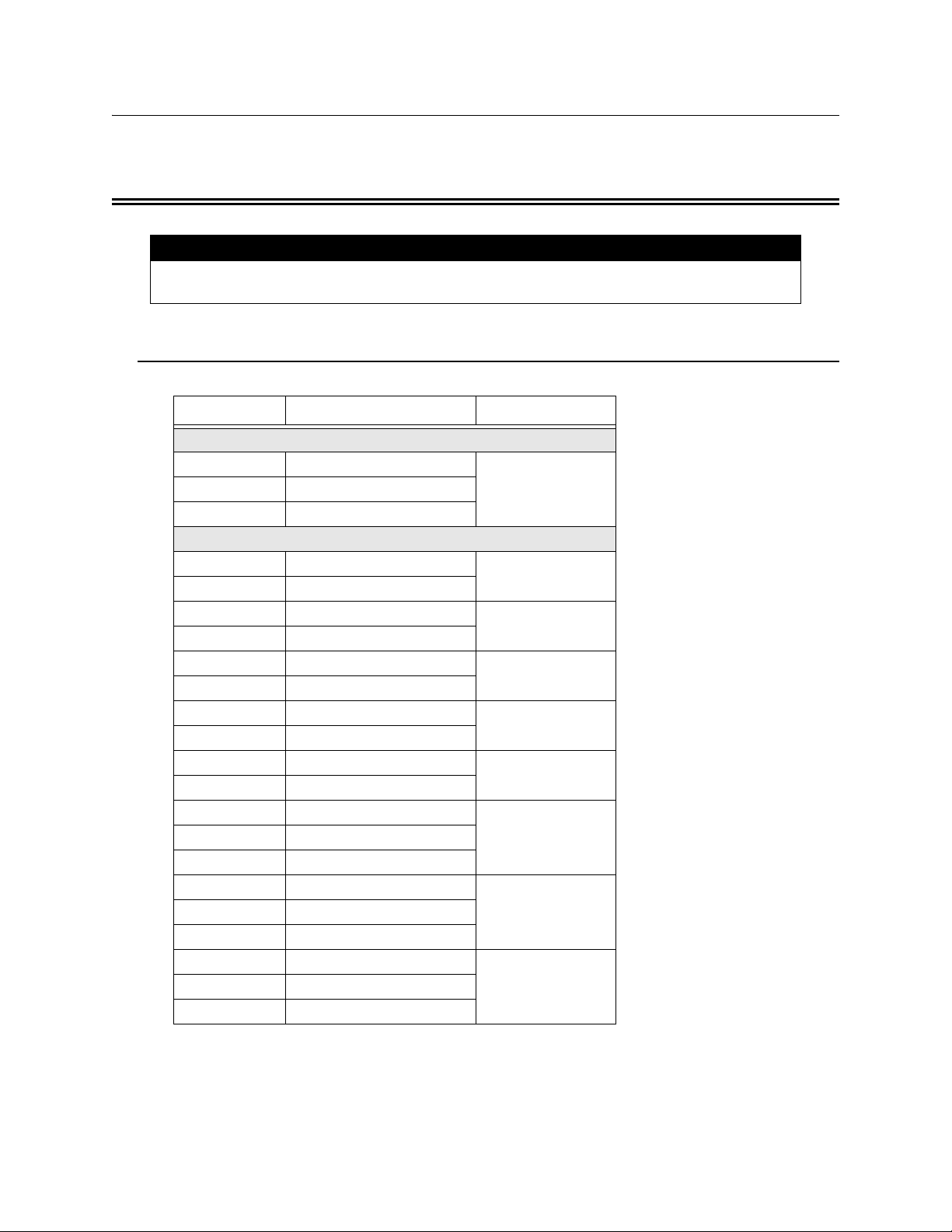
3.1 Terminal Descriptions and Electrical Ratings
Terminal # Description Ratings
TB1
1 AC (black–“hot”)
120 VAC 60 Hz, A2 Earth Ground
3 AC (white–“neutral”)
TB2
1 Auxiliary Power (-)
2 Auxiliary Power (+)
3 Notification 4 Output (-)
4 Notification 4 Output (+) Although each output
5 Notification 3 Output (-)
6 Notification 3 Output (+) total current draw from
7 Notification 2 Output (-)
8 Notification 2 Output (+) auxiliary power must
9 Notification 1 Output (-)
10 Notification 1 Output (+)
11 Normally Closed contact 2.5 A @ 250 VAC
12 Common
13 Normally Open contact
14 Input 2
16 Input 2 (+)
17 Input 1
19 Input 1 (+)
27.4 VDC 3.0 amps
27.4 VDC 3.0 amps
27.4 VDC 3.0 amps
27.4 VDC 3.0 amps
27.4 VDC 3.0 amps
or
2.5 A @ 30 VDC
9 - 30 VDC15 Input 2 (-)
9 - 30 VDC18 Input 1 (-)
is rated for 3 amps, the
the 4 outputs and the
not exceed 6 amps.
151341 3
Page 8

HPF602ULADA Distributed Power Module Installation Manual
3.2 Signal Input Terminals
Terminals 14 through 19 are polarized signal input terminals. They provide the signaling
connection from the main panel to the HPF602ULADA. See Figure 4-2 for more details.
The main panel supervises its notification appliance circuits used for communicating with the
HPF602ULADA the same way it supervises ordinary notification appliance circuits. The
signal inputs on the HPF602ULADA monitor the polarity of the voltage coming from the
main panel’s notification appliance circuits to determine when to operate the notification
appliance circuits on the HPF602ULADA. The HPF602ULADA emulates the trouble
behavior of a normal notification appliance circuit by interrupting the EOL supervision
current for internal or output trouble conditions on the HPF602ULADA.
Note that the HPF602ULADA will accurately sense the polarity of the main panel’s
notification appliance circuits to drive the outputs whether or not the supervision connection
is intact. The following situations will disconnect the EOL supervision at the signal inputs and
indicate a trouble condition:
• Low AC power
• Low Battery condition
• Earth ground fault to the system power or system ground
• Auxiliary output power-limited condition
• EOL supervision trouble or power-limited condition at an output
Trouble conditions will not necessarily occur for both inputs when the trouble is specific to a
particular output. Only the signal input controlling the output circuit that is in trouble will
indicate a trouble condition. Below are examples where both inputs do NOT indicate trouble
for a trouble occurring at only one output circuit.
Example 1: If input 1 controls all four outputs, a fault on any output will cause input 1
to indicate trouble. The fault does not affect input 2.
Example 2: If input 1 controls outputs 1 and 2, and input 2 controls outputs 3 and 4, a
fault condition on output 3 or 4 will cause input 2 to indicate trouble. The
fault does not affect input 1.
Note:Once the inputs are driven with forward polarity to activate the outputs, the main control panel will not be
able to sense trouble conditions through its notification appliance circuit connected to the HPF602ULADA
input circuits. Use the HPF602ULADA trouble relay when it is necessary to monitor trouble conditions
and active alarm conditions at the same time.
Section 6 explains the significance of each trouble condition in more detail.
4 151341
Page 9

System Overview
3.3 Notification Appliance Circuit Terminals
T erminals 3 through 10 are the notification appliance circuit output terminals. Each of the four
circuits are rated at 3 amps, although you can only draw a total of 6 amps from the
HPF602ULADA. The HPF602ULADA outputs are short-circuit protected (power limited)
according to UL 864 standards. Overcurrent indicators are yellow LEDs. The output voltage
can vary depending on the load and input voltage.
The four power-limited NAC outputs can be configured as follows:
• Four Class B circuits • Faraday synchronized outputs
• Two Class A circuits • Gentex synchronized outputs
• One Class A and two Class B circuits • System Sensor synchronized outputs
• Class B, ANSI temporal-coded circuits • Wheelock synchronization outputs
• AMSECO synchronized outputs
One or both HPF602ULADA signal inputs control the NAC outputs, depending on the
specific configuration setup. Possible configurations for the HPF602ULADA are:
For Option: These Inputs: Control These Outputs: As:
1 Input 1 All outputs Class B circuits
2
3
4
5 Input 1 Outputs 1-2 and 3-4 Class A circuit pairs
6
7
8
9
10
11
12
13
Input 1 or
Input 2 coded circuits
Input 1 Outputs 1 and 2 Class B circuits
Input 2 Outputs 3 and 4 Class B circuits
Input 1 Output 1 Class B circuits
Input 2 Outputs 2, 3, and 4 Class B circuits
Input 1 Outputs 1 and 2 Class B ANSI temporal-coded circuits
Input 2 Outputs 3 and 4 Class B circuits
Input 1 Outputs 1-2 Class A circuit pair
Input 2 Outputs 3-4 Class A circuit pair
Input 1 Outputs 1-2 Class A circuit pair
Input 2 Outputs 3 and 4 Class B circuits
Input 1 (Strobe Control)
Input 2 (Audio Control) Faraday Sync. Output
Input 1 (Strobe Control)
Input 2 (Audio Control) Gentex Sync. Output
Input 1 (Strobe Control)
Input 2 (Audio Control) System Sensor Sync. Output
Input 1 (Strobe Control)
Input 2 (Audio Control) Wheelock Sync. Output
Input 1 (Strobe Control)
Input 2 (Audio Control) Amseco Sync. Output
Outputs 1, 2, 3, and 4
All outputs
All outputs
All outputs
All outputs
All outputs
Class B ANSI temporal-
Class A or Class B
Class A or Class B
Class A or Class B
Class A or Class B
Class A or Class B
You can select which input controls which output, and which inputs are Class A and Class B
using the 7-position DIP switch on the printed circuit board. Section 4.8 for DIP switch
settings.
151341 5
Page 10

HPF602ULADA Distributed Power Module Installation Manual
Section 4 Installation
Before installing the HPF602ULADA, the AC input must first be wired into the building’s
main electrical power through the TB1 terminals (see Figure 4-2). Shut off the electrical
power to the HPF602ULADA, and then complete the general installation of the
HPF602ULADA using the information in this section.
4.1 Mounting
Mount the HPF602ULADA in locations that meet the following temperature and humidity
requirements. Do not expose the panel to conditions outside these ranges. For use in indoor,
dry environments.
Temperature
Humidity
When mounting on interior walls, use appropriate screw anchors in plaster. When mounting
on concrete, especially when moisture is expected, first attach a piece of 3/4-inch plywood to
the concrete surface. Attach the HPF602ULADA to the plywood.
o
C-49o C (32o F-120o F)
0
10%-93% at 30o C (86o F) noncondensing
4.1.1 Preventing Water Damage
Water damage to the fire system can be caused by moisture entering the cabinet through the
conduits. Conduits that are installed to enter the top of the cabinet are most likely to cause
water problems. Installers should take reasonable precautions to prevent water from entering
the cabinet. Water damage is not covered under warranty.
6 151341
Page 11
Installation
Note: The use of
this knock out will
reduce the number
and/or size of
batteries this cabinet can
contain. Evaluation of space is
important before using.
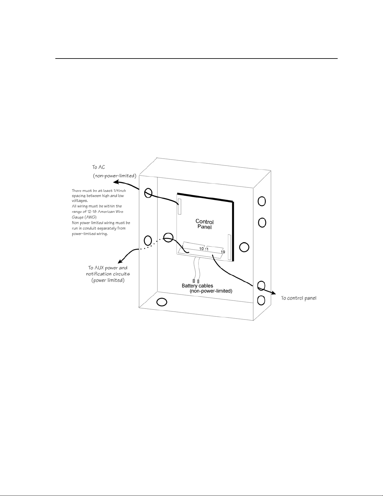
4.2 Wire Routing
To avoid induced noise (transfer of electrical energy from one wire to another), keep input
wiring isolated from high current output and power-limited wiring. Induced noise can
interfere with telephone communication or even cause false alarms. Avoid pulling a single
multiconductor cable for the entire system. Instead, separate high current input/output from
low current. Separate power-limited from non-power-limited wiring. Non-power-limited
wiring must be enclosed in conduit.
Wiring within the cabinet should be routed around the perimeter of the cabinet. It should not
cross the printed circuit board where it could induce noise into the sensitive microelectronics
or pick up unwanted RF noise from the switching power supply circuit.
Figure 4-1 Sample Wire Routing
151341 7
Page 12

HPF602ULADA Distributed Power Module Installation Manual
4.3 Current Requirements (Standby and Alarm)
4.3.1 Current Drawn From Host Panel
Table 4-1 shows the HPF602ULADA current draw requirements from the main control panel
when the panel’s notification appliance circuit is in alarm. The current draw from the main
panel when it is supervising the HPF602ULADA is the same current draw that would be
present when the main panel supervises an ordinary notification appliance circuit.
Table 4-1: Alarm Current Drawn From Main Control Panel
Panel Voltage Current
Alarm Current (for typical voltages)
drawn from main panel’s notification
appliance
circuits.
4.3.2 Current Drawn from Battery
12 VDC 6.5 mA
24 VDC One input circuit: 15 mA
Both input circuits: 30 mA
Batteries used with the HPF602ULADA must not exceed 35AH. (33AH max. for FM
(Factory Mutual) Installations). Batteries larger than 7 AH will not fit into the
HPF602ULADA cabinet and must be housed in the RBB Remote Battery Box. See Section
4.7 for battery installation.
The following is the maximum current draw from the auxiliary power terminals for standby
calculations. These currents assume 24 or 60 hours of standby time, followed by 5 minutes of
maximum alarm current.
• 195 mA for 24 Hour Standby Current
• 39 mA for 60 Hours of Auxiliary Standby Current
The above numbers were calculated assuming the use of 7 AH batteries at 100% of rated
capacity.
The total current of the HPF602ULADA, plus all items powered from it, must not exceed 6 A
when the panel is in alarm. Use Table 4-2 to ensure that the current does not exceed 6 A and,
that the desired amount of standby is possible for the battery intended for use with the
HPF602ULADA.
4.3.2.1 CAN/ULC-S527
Per CAN/ULC-S527, the maximum current draw from the auxiliary power terminals for
standby calculations is 39 mA for 24 hours standby current. The current assumes 24 hours of
standby time, followed by 30 minutes of maximum alarm current.
8 151341
Page 13
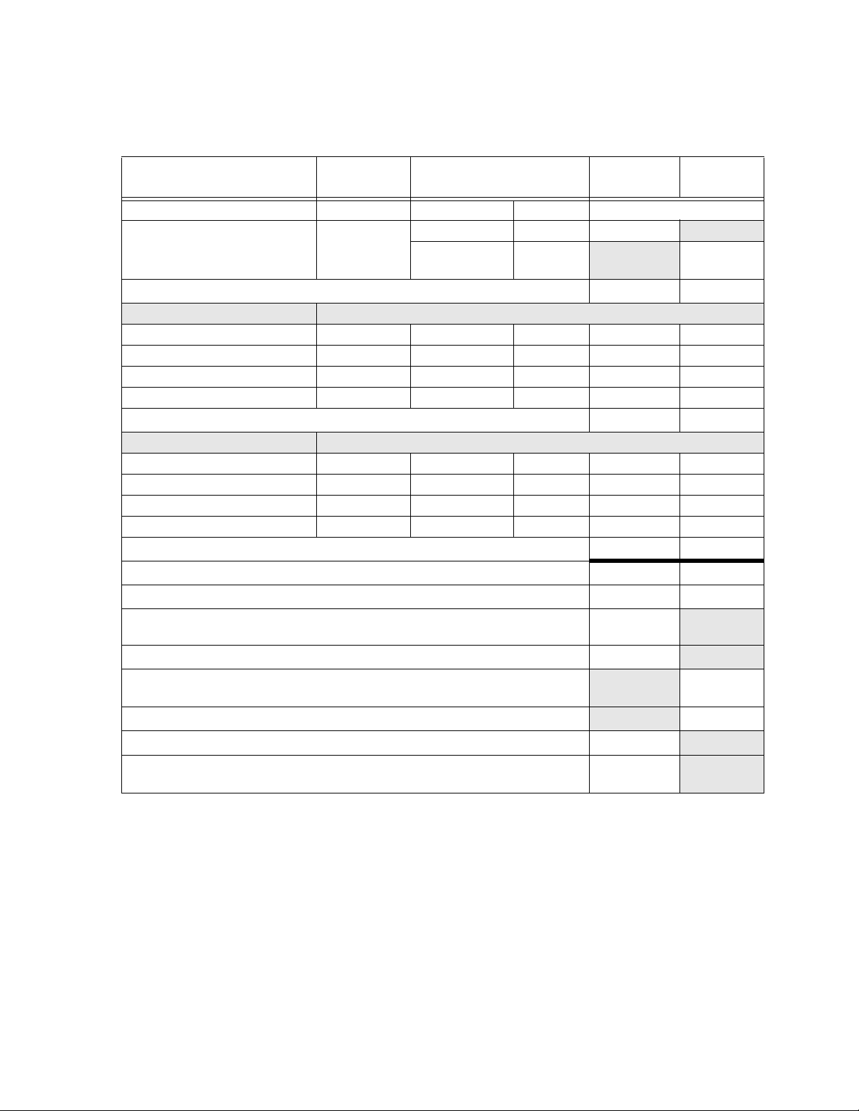
Table 4-2: Battery Calculation Worksheet
Installation
Device
For each device use this formula: This column X This column = Current per number of devices.
HPF602ULADA Distributed Power
Module
(Current draw from battery)
A
Auxiliary Devices Refer to device manual for current ratings.
B
Notification appliances Refer to device manual for current ratings.
C
Total current ratings of all devices in system (line A + line B + line C)
D
Total current ratings converted to amperes (line D x .001):
E
Number of standby hours (24 or 60 for NFPA 72, Chapter 1, 1-5.2.5). 24 Hrs. for NBC,
F
section 3.2.7.8
Multiply lines E and F. Total standby AH
G
Alarm sounding period in hours. In accordance with NBC and ULC.
H
(For example, 5 minutes = .0833 hours, or for ULC installations 30 minutes = 0.5 hours.)
Multiply lines E and H. Total alarm AH
I
Add lines G and I. Total standby and alarm AH
J
Multiply line J by 1.20.
K
(20% extra insurance to meet desired performance) Total ampere-hours required
Number of
Devices
1
Current per Device
Standby: 75 mA 75 mA
Alarm: 205 mA 205 mA
HPF602ULADA Current 75 mA 205 mA
Alarm/Standby mA mA mA
Alarm/Standby mA mA mA
Alarm/Standby mA mA mA
Alarm/Standby mA mA mA
Auxiliary Device Current mA mA
Alarm: mA 0 mA mA
Alarm: mA 0 mA mA
Alarm: mA 0 mA mA
Alarm: mA 0 mA mA
Notification Appliance Current
Standby
Current
0 mA mA
mA mA
AA
H
AH
AH
AH
Alarm
Current
H
AH
151341 9
Page 14
HPF602ULADA Distributed Power Module Installation Manual
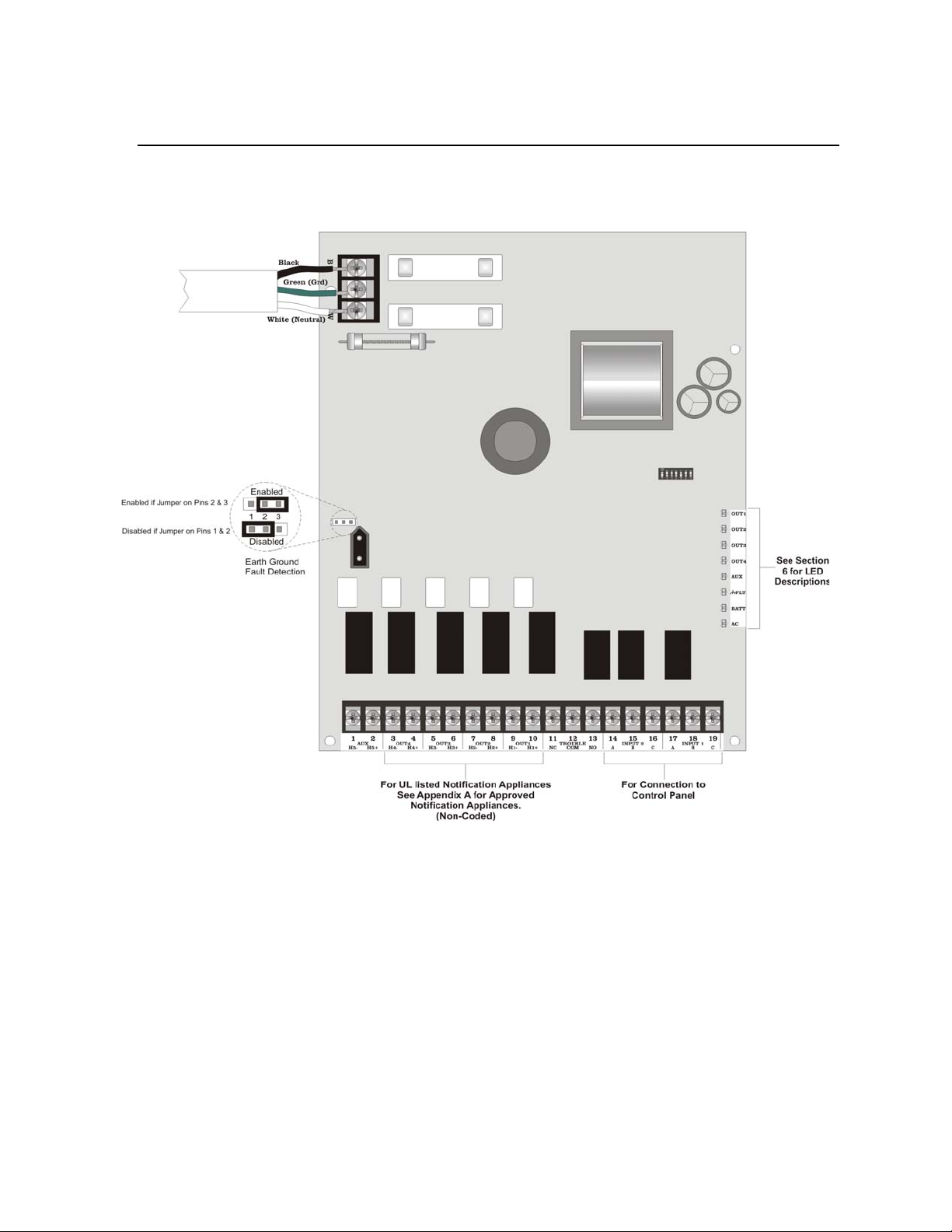
4.4 Connecting the HPF602ULADA to a FACP
Figure 4-2 shows the general layout of the HPF602ULADA PC board. This section also
provides specific wiring details for accessories.
Figure 4-2 The Model HPF602ULADA PC Board Layout
Consult the installation manual for specific wiring information for the control panel being
used.
10 151341
Page 15
Installation
Must be connected to
a power limited source
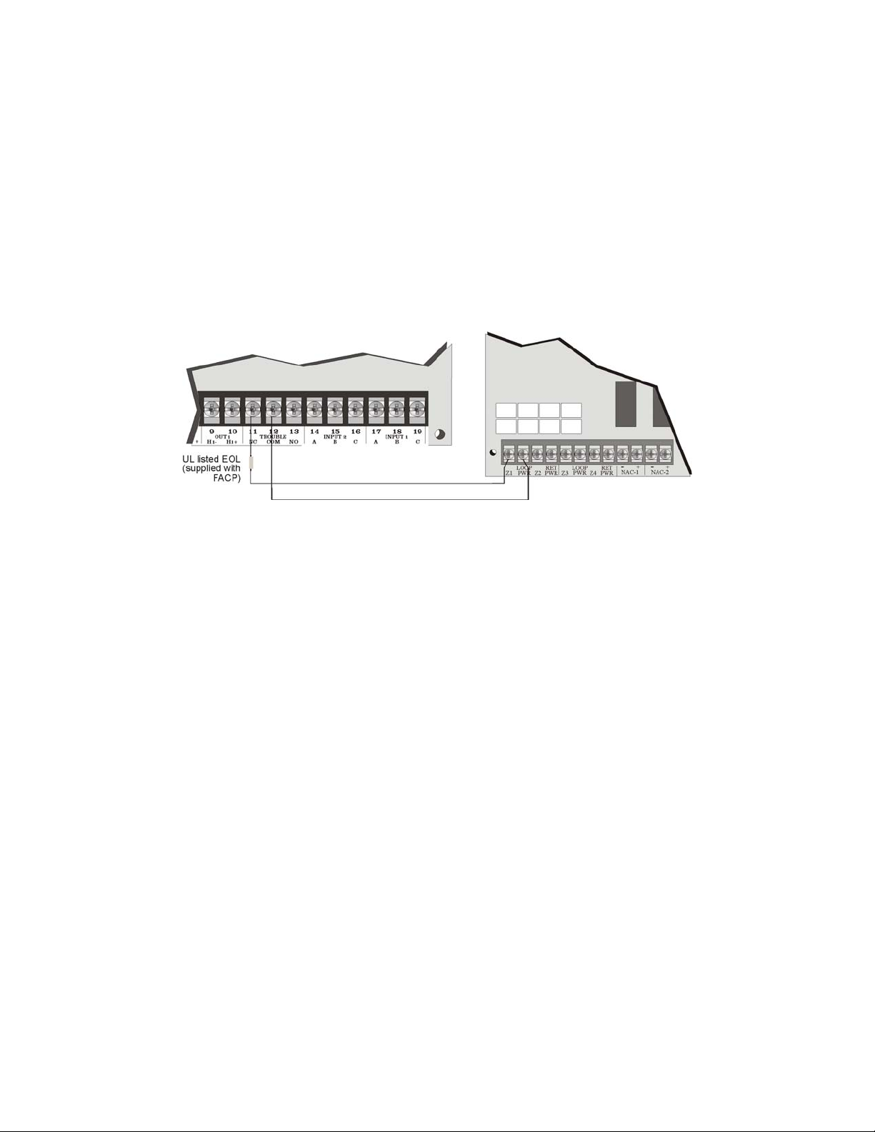
4.4.1 Common Trouble Relay
The HPF602ULADA has a Form C trouble relay built into Terminals 11-13. The relay
provides a normally open and a normally closed contact, both of which are rated at 2.5A. The
trouble relay will deactivate under any trouble condition.
A typical application of the trouble relay is to connect the HPF602ULADA normally closed
(N.C.) contacts in series with the EOL supplied with the fire alarm control panel. This will
cause a trouble on the fire alarm control panel when the HPF602ULADA opens its trouble
contacts.
Note:The N.C. contact is the contact that is closed when the HPF602ULADA has power and there are no trouble
conditions.
Figure 4-3 Trouble Relay Connection Example
151341 11
Page 16

HPF602ULADA Distributed Power Module Installation Manual
4.5 Notification Appliance Wiring
Note:Not all devices can use the sync feature. Be sure to check Appendix A to ensure the device you have chosen
will work with this feature.
Important!
For all synchronization options, input 1 is the strobe input and input 2 is the audible input. The signals to input 1 and input 2
must be DC signals for the synchronization patterns to work properly. When it is desired to activate both strobes and audibles,
input 1 and input 2 must be active. If it is desired to only activate strobes, then input 1 must be active and input 2 must be
inactive. The audible can be deactivated and reactivated at any time by changing the signal at input 2 as long as input 1
remains active. If input 1 is not active, then input 2 is ignored.
4.5.1 Class A Supervised Wiring
Figure 4-4 shows how to wire for Class A input and output supervision. Use in/out wiring
methods for proper supervision. (Refer to Appendix A for notification appliances compatible
with the HPF602ULADA.)
Class A Output Notification Circuits
The configuration shown in Figure 4-4 shows two, 3 A devices wired as Class A. When using
the outputs as Class A circuits, loop the wiring back to the corresponding circuit pair. For
Class A wiring, no external EOL is necessary since it is built into the HPF602ULADA board.
Class A Supervised Input Circuits
The configuration shown in Figure 4-4 shows Class A supervised wiring from a fire alarm
control panel to the HPF602ULADA board. Pay close attention to the polarities when wiring a
panel to the HPF602ULADA and follow these requirements:
• When wiring to Terminal 18 on the HPF602ULADA, you must use two separate wires.
Do not loop a single wire or twist two conductors together.
• Do not use notification appliances on Class A circuits connected to a HPF602ULADA for
input. The HPF602ULADA will detect voltage across the input circuits, but is not
12 151341
Page 17

designed to pass the added current load from notification appliances.
Installation
Figure 4-4 Class A Supervised Input/Output Connections
4.5.2 Class B Supervised Wiring
Figure 4-5 shows how to wire for Class B input and output supervision. Use in/out wiring
methods for proper supervision (Refer to the Appendix for notification appliances approved
for use with the HPF602ULADA.)
Class B Output Notification Circuits
Figure 4-5 shows four, 1.5 A devices wired as Class B.
Place a 4.7k ohm EOL resistor (provided) at the end of each circuit to enable supervision
when using all outputs as Class B notification appliance circuits. The 4.7k EOLs must be
wired to the terminals whether or not you are using all output terminals.
151341 13
Page 18

HPF602ULADA Distributed Power Module Installation Manual
Class B Supervised Input Circuits
Figure 4-5 shows Class B supervised wiring from a fire alarm control panel to the
HPF602ULADA.
Use an EOL resistor as shown to enable notification appliance circuit input supervision. Some
panels use EOLs that have a different value from the 4.7k ohm EOL resistor used by the
HPF602ULADA. In this case, the EOL must be UL listed for the fire alarm control panel (not
the HPF602ULADA).
Figure 4-5 Class B Supervised Input/Output Connections
4.6 Ground Fault Detection Enable/Disable Jumper
In some cases the ground fault detection feature on the HPF602ULADA may interfere with
the ground fault detection feature of the main control panel in the system. To disable the
ground fault detection feature on the HPF602ULADA, place the jumper block on J1, across
Pins 1 and 2 (see Figure 4-2).
14 151341
Page 19

Installation
Model 6712
(Supervised)
Jumper
(P/N140694)
4.7 Battery Connection
Use two 12 VDC, 7 AH gel cell batteries inside the HPF602ULADA cabinet. For batteries
larger than 7 AH (not to exceed 35 AH) use the RBB Remote Battery Box. It is recommended
that you replace the batteries every five years. The following steps and diagram explain how
to connect the batteries.
1. Connect the black wire to the negative (-) side of Battery #1.
2. Connect the jumper wire provided (PN 140694) from the positive (+) side of Battery #1 to
the negative side of Battery #2.
3. Connect the red wire to the positive (+) side of Battery #2.
Figure 4-6 Battery Connection
4.8 DIP Switch Settings
A 7-position DIP switch on the HPF602ULADA board allows you to select the following:
• How long the HPF602ULADA will wait before indicating a loss of AC.
• Which input (Input 1 or Input 2) will control the NACs.
• Which NACs to wire as Class A and Class B.
• Auxiliary power state.
• Which NACs to operate as steady, ANSI temporal, or sync. outputs
Refer to Figure 4-2 for the location of the DIP switch on the HPF602ULADA board.
151341 15
Page 20

HPF602ULADA Distributed Power Module Installation Manual
4.8.1 Selecting the Standard Input/Output Configurations
Figure 4-7 and Figure 4-8 show the position of each switch for the non-synchronized input
and output configurations. The position of Switches 4 and 5 does not affect the relationship of
inputs to outputs.
Note:The HPF602ULADA checks switches 1, 2, 3, and 6 only when powering up the HPF602ULADA. If you
change these switch settings, you must remove both the AC power and the battery to make the
HPF602ULADA recognize the new settings.
Figure 4-7 Setting DIP Switches 1-3
Figure 4-8 Setting DIP Switches 1-3 (Continued)
Note:For 100 mS input signal debounce with no synchronization DIP switches 6 and 7 must be turned On.
16 151341
Page 21

Installation
4.8.1.1 Input/Output Configurations That Select ANSI
Temporal-Coded Outputs
The DIP switch settings marked with an asterisk (*) in Figure 4-7 and Figure 4-8 are designed
to produce ANSI temporal-coded outputs from a constant input. The figures shown below
compare the output patterns of configurations before and after the addition of this feature.
Standard HPF602ULADA Input to Output Relationship
Input/Output Relationship for ANSI
Temporal-coded Options
With this new feature, a steady signal can produce the pattern shown above for panels not
previously able to do so.
Note:The HPF602ULADA can also produce temporal patterns if the inputs are non-ANSI temporal configura-
tions.
151341 17
Page 22

HPF602ULADA Distributed Power Module Installation Manual
4.8.2 Selecting Synchronized Output Configurations
The following sections describe how to configure the HPF602ULADA as a synchronization
power expander for Amseco, Faraday, Gentex, System Sensor, or Wheelock synchronized
horn/strobe appliances.
Note:In order for the synchronization feature to operate properly, make sure you have set the DIP switches for
the proper manufacturer. See Sections 4.8.2.1, 4.8.2.2, or 4.8.2.3.
Important!
For all synchronization options, input 1 is the strobe input and input 2 is the audible input. The signals to input 1 and input 2
must be DC signals for the synchronization patterns to work properly. When it is desired to activate both strobes and audibles,
input 1 and input 2 must be active. If it is desired to only activate strobes, then input 1 must be active and input 2 must be
inactive. The audible can be deactivated and reactivated at any time by changing the signal at input 2 as long as input 1
remains active. If input 1 is not active, then input 2 is ignored.
4.8.2.1 Selecting Synchronized Faraday Configurations
To select the input/outputs for Faraday synchronized appliances, set the DIP switches as
shown in Figure 4-9.
Figure 4-9 Faraday Synchronized Configurations
4.8.2.2 Selecting Synchronized Gentex Configurations
T o select the input/outputs for Gentex synchronized appliances, set the DIP switches as shown
in Figure 4-10.
Figure 4-10 Gentex Synchronized Configurations
18 151341
Page 23

Installation
4.8.2.3 Selecting Synchronized System Sensor Configurations
To select the input/outputs for System Sensor synchronized appliances, set the DIP switches
as shown in Figure 4-11.
Figure 4-11 System Sensor Synchronized Configurations
4.8.2.4 Selecting Synchronized Wheelock Configurations
To select the input/outputs for Wheelock synchronized appliances, set the DIP switches as
shown in Figure 4-12.
Figure 4-12 Wheelock Synchronized Configurations
4.8.2.5 Selecting Synchronized AMSECO Configurations
To select the input/outputs for AMSECO synchronized appliances, set the DIP switches as
shown in Figure 4-13.
Figure 4-13 AMSECO Synchronized Configurations
151341 19
Page 24

HPF602ULADA Distributed Power Module Installation Manual
4.8.3 Setting the Loss of AC Delay
Normal selection for reporting loss of AC is 3 hours.
The ON position is for test purposes only and the normal position for Switch 4 is OFF. For
testing the Low AC reporting, you can temporarily turn Switch 4 ON without removing
power.
Note:Remember to turn the switch OFF when testing is complete.
Figure 4-14 Setting DIP Switch 4
4.8.4 Setting the Auxiliary Output
Switch 5 on the DIP switch determines how the auxiliary power operates on the
HPF602ULADA.
The HPF602ULADA checks Switch 5 only when powering up the HPF602ULADA. If you
change this switch, you must remove both the AC power and the battery to force the
HPF602ULADA to recognize the new switch setting.
Figure 4-15 Setting DIP Switch 5
20 151341
Page 25

Sample Applications
HPF602ULADA
Local Fire Alarm
Control Panel
Local Fire Alarm
Control Panel
HPF602ULADA
Section 5 Sample Applications
The drawings in this section show various HPF602ULADA configurations, including
“daisy-chaining”.
5.1 Notification Power Applications
Figure 5-1 Input 1 Activates All Four Outputs
Figure 5-2 Input 1 Activates NACs 1 and 2; Input 2 Activates NACs 3 and 4
151341 21
Page 26

HPF602ULADA Distributed Power Module Installation Manual
HPF602ULADA
HPF602ULADA
Local Fire Alarm
Control Panel
HPF602ULADA
HPF602ULADA
HPF602ULADA
Local Fire Alarm
Control Panel
Note:When multiple power supplies are used with one control unit they will not sync with each other
Figure 5-3 One Control Activating Two HPF602ULADAs
22 151341
Figure 5-4 One Control Activating Three HPF602ULADAs in Series
Page 27

Sample Applications
HPF602ULADA
HPF602ULADA
HPF602ULADA
Local Fire Alarm
Control Panel
Figure 5-5 Each Control NAC Activates Five Output NACs
5.2 Non-Resettable Power Application
The HPF602ULADA provides a dedicated 3 A auxiliary power output that you can select as
non-resettable (output is always on). See Section 4.8.4 for setting the auxiliary power. If you
need more than 3 A, wire the inputs as shown in Figure 5-6.
Figure 5-6 Auxiliary Output Wiring for Non-Resettable Power
151341 23
Page 28

HPF602ULADA Distributed Power Module Installation Manual
HPF602ULADA
Fire Alarm Panel
ESL DHX 1224
5.3 Door Holder Application
In a typical door holder application, the door holder power must be interrupted to close all fire
doors under the following conditions:
• Any active alarm condition.
• AC power failure (to conserve battery power).
T o close the fire doors in these situations, wire an N.C. programmable relay from the FACP in
series with the auxiliary power to the door holders as shown in Figure 5-7.
The circuit shown in Figure 5-7 will provide up to 3 amps of door holder power. (See Section
5.2 if you need more than 3 amps of auxiliary power.) The power in this example is released
when AC power is off for 30 seconds or more, or when the relay from the fire alarm control
panel becomes open. You would have to use the equivalent of a programmable relay from a
fire alarm control panel that is programmed to open under alarm conditions. See Section 4.8.4
for selecting auxiliary power options.
Figure 5-7 Door Holder Wiring Example
24 151341
Page 29

Troubleshooting
Section 6 Troubleshooting
Light-emitting diodes (LEDs) indicate fault conditions. This section describes the LED states.
6.1 LEDs
The eight LEDs indicate a fault in one of the circuits (either NACs 1 through 4, auxiliary
power, earth fault, low AC, or battery). A fault in the LED's corresponding circuit will light
the LED (labeled on the board). Their functions are as follows:
LED Color Description
OUT1 Yellow When ON, output circuit 1 is in trouble or in an overcurrent state.
OUT2 Yellow When ON, output circuit 2 is in trouble or in an overcurrent state.
OUT3 Yellow When ON, output circuit 3 is in trouble or in an overcurrent state.
OUT4 Yellow When ON, output circuit 4 is in trouble or in an overcurrent state.
AUX Yellow When ON, the auxiliary power output is in an overcurrent state.
FLT Yellow When ON, an earth ground fault on the unit exists.
BATT Yellow When ON, a low battery condition exists.
AC Green When OFF , there is no AC power to the unit. Under normal conditions, this LED is ON
to indicate the presence of AC power.
See Figure 4-2 for locations of LEDs.
151341 25
Page 30

HPF602ULADA Distributed Power Module Installation Manual
6.2 Trouble Conditions
Trouble Condition What Happens
Low AC
(AC input voltage is low or off
for 6 hours or longer.)
Low Battery
(Battery voltage is less than
21.4 VDC.)
Earth Ground Fault
(The earth terminal is connected
to one of the positive or
negative terminals on the output
or auxiliary output circuits.)
Power Limit At AUX
(Current draw at the auxiliary
power terminals is exceeding
3.0 amps.)
Power-limited OUTPUT
(Current draw at an output
terminal is exceeding 3.0
amps.)
EOL supervision trouble
(Equivalent resistance of the
EOL resistor is outside the
range 2k - 10k.)
Input 1 and Input 2 supervision circuits open after a 6 hour delay.
The green AC LED turns off as soon as low AC or loss of AC occurs (does not wait 6 hours).
The trouble relay is de-energized after a 6 hour delay.
The trouble restores within 1 minute of the AC voltage restoring to a normal level.
Input 1 and Input 2 supervision circuits open. The yellow “BATT” LED lights.
The trouble relay is de-energized.
The trouble restores when battery voltage is greater than 22.4 VDC.
Input 1 and Input 2 supervision circuits open. The yellow “FLT” LED lights.
The trouble relay is de-energized.
The trouble restores when the fault between the earth ground and one of the output circuit
terminals is removed.
Power disconnects at the AUX terminal. Input 1 and Input 2 supervision circuits open. The
yellow “AUX” LED lights. The trouble relay is de-energized.
The trouble restores when the overcurrent condition no longer exists. When a circuit goes into
a power limited state, it will reverse the polarity of the voltage at the terminals and verify the
load. If it is more than 1k ohms, the power limit will self-restore.
This does not automatically occur for some devices typically connected to auxiliary power.
Power limit conditions do not restore in reverse polarity monitoring if the devices are not
polarized (for example, some door holder devices). To allow automatic restores for
power-limited auxiliary circuits, it is recommended that all non-polarized devices be polarized
using a diode in series with each device.
Power at the OUTPUT is disconnected. Input 1 and Input 2 supervision circuits open. The
corresponding yellow LED lights. The trouble relay is de-energized.
The trouble restores when the overcurrent condition no longer exists.
Input 1 and Input 2 supervision circuits open. Corresponding yellow LED lights.
The trouble relay is de-energized.
Trouble restores if an EOL within (2k-10k) appears at the output terminals.
Note: While Input 1 & 2 are activated, Input 1 & 2 will not open to indicate a trouble or supervisory condition.
Once the circuit is deactivated it will open to indicate a trouble or supervisory condition.
26 151341
Page 31

Troubleshooting
6.3 Earth Fault Resistance
Table 6-1 lists the earth fault resistance detection for each applicable terminal on the FACP.
Table 6-1: Earth Fault Resistance Values by Terminal
Function
Auxiliary Devices
Notification Appliance
Circuit 4
Notification Appliance
Circuit 3
Notification Appliance
Circuit 2
Notification Appliance
Circuit 1
Terminal
Number
1H52 H5+ 0
3H44 H4+ 0
5H36 H3+ 0
7H28 H2+ 0
9H110 H1+ 0
Terminal Label
AUX
OUT4
OUT3
OUT2
OUT1
Value
(in kohms)
0
0
0
0
0
151341 27
Page 32

HPF602ULADA Distributed Power Module Installation Manual
6.4 Removing and Replacing the Control Panel
This section provides instruction on how to remove and replace the control panel if it is
determined that the control panel needs to be repaired or replaced.
6.4.1 Removing the Control Panel
Follow these step to properly remove the control panel:
1. Remove the two heat sink screws. The heat sink screws are located on the top of the
cabinet. See Figure 6-1.
Figure 6-1 Mounting Screw Locations
2. Remove the four chassis mounting screws. See Figure 6-1 for chassis screw locations.
3. Carefully remove the control panel.
6.4.2 Replacing the Control Panel
Follow these steps to replace the control panel:
Note:Use a grounding strap when working with static sensitive components.
1. Align the control panel with the chassis mounting stand-offs. See Figure 6-1.
2. Insert the four chassis mounting screws (see Figure 6-1). Do not over tighten the chassis
mounting screws.
3. Insert the two heat sink screws (see Figure 6-1). Do not over tighten the heat sink screws.
Note:The heat sink screws must be installed for proper heat dispersion of the power module’s power supply.
28 151341
Page 33

Appendix A UL Listed Notification Appliances
For proper operation, you must use polarized devices with a Model 7628 4.7k ohm EOL
resistor on each circuit. All supervised notification appliances used with the HPF602ULADA
must be polarized.
Note:Not all devices can use the Sync feature, be sure to check Table A-1 to ensure the device you have chosen
will work with this feature. Synchronization is UL listed for multi-circuit operation.
A.1 Notification Appliances
Table A-1 below lists notification appliances compatible with the HPF602ULADA.
Appliances which can be synchronized indicate the type of sync available in the
columns marked Audio and/or Visual
Table A-1: Compatible Notification Appliances
Manufacturer Model Audio Visual Type
SH24W-153075 Horn/Strobe
AMSECO
SAD24-153075 Strobe
SAD24-75110 Strobe
SL24W-75110 Strobe
SL24C-3075110 Strobe
SLB24-75 Strobe
RSD24-153075 Strobe
RSD24-75110 Strobe
SH24W-75110 Horn/Strobe
SH24W-3075110 Horn/Strobe
SHB24-75 Horn/Strobe
SCM24W-153075 Chimes/Strobe
SCM24W-75110 Chimes/Strobe
SCM24C-3075110 Chimes/Strobe
SCM24C-177 Chimes/Strobe
H24W Horn
H24R Horn
151341 29
Page 34

HPF602ULADA Distributed Power Module Installation Manual
Table A-1: Compatible Notification Appliances
Manufacturer Model Audio Visual Type
446 Vibrating Bell
476 Vibrating Bell
477 Single Stroke Bell
2700 -M. -R, -T, -Y, -Z Strobe
2701 Series Strobe
2705 Series Strobe
2820 Snyc T emporal Horn/Strobe
2821 Snyc T emporal Horn/Strobe
2824 Horn Strobe
5333 Multi-Tone Horn)
5336 Multi-Tone Horn/Strobe
5337 Multi-Tone Horn/Strobe
Faraday
5338 Multi-Tone Horn/Strobe
5343 Single Tone Horn/Strobe
5346 Electronic Horn with Strobe
5347 Electronic Horn with Strobe
5348 Single Tone Horn/Strobe
5373 8-Tone Horn/Strobe
6321 Sync Mini Horn/Strobe
6322 Mini Horn/Sync Strobe
6380 8-Tone Electronic Signal/Strobe
5376 8-Tone Horn/Strobe
5377 8-Tone Horn/Strobe
5378 8-Tone Horn/Strobe
5383 8-Tone Horn/Strobe with Sync Strobe
5386 8-Tone Horn/Strobe with Sync Strobe
5387 8-Tone Horn/Strobe with Sync Strobe
5388 8-Tone Horn/Strobe with Sync Strobe
5508 Single Gang Sync Strobe
5509 Strobe
30 151341
Page 35

UL Listed Notification Appliances
Table A-1: Compatible Notification Appliances
Manufacturer Model Audio Visual Type
5510 Strobe
5511 Strobe
5512 Strobe
5516 Strobe
5517 Strobe
5518 Strobe
5519 Strobe
5521 4” Square Sync Strobe
5522 4” Square Sync Strobe
6120 Horn
6140 Horn
6223 Horn
Faraday
con’t
6226 Horn/Strobe
6227 Horn/Strobe
6228 Horn/Strobe
6243 Electron-Mechanical Horn
6244 Electron-Mechanical Horn
6245 Electron-Mechanical Horn
6246 Electron-Mechanical Horn/Strobe
6247 Electron-Mechanical Horn/Strobe
6248 Electron-Mechanical Horn/Strobe
6300 Mini-Horn
6301 Mini-Horn
6302 Mini-Horn
6310 Mini-Horn/Strobe
6311 Mini-Horn/Strobe
6312 Mini-Horn/Strobe
6314 Series -M, -R, -T, -Y, -Z Strobe
6320 Sync Mini Horn/Strobe
151341 31
Page 36

HPF602ULADA Distributed Power Module Installation Manual
Table A-1: Compatible Notification Appliances
Manufacturer Model Audio Visual Type
S2415-FC Strobe
S241575-FC Strobe
S2430-FC Strobe
130-3117C Mini Horn
130-3147C Mini Horn
BLV-6 Vibrating Bell
BLV-10 Vibrating Bell
BLVCH Vibrating Chime
H12/24-FC Horn
H12/24W-FC Horn
FCI
H12/24K-FC Horn
HC12/24-FC Horn
HC12/24W-FC Horn
HC12/24K-FC Horn
P2415-FC Horn/Strobe
P2415W-FC Horn/Strobe
P2415K-FC Horn/Strobe
P241575-FC Horn/Strobe
P241575W-FC Horn/Strobe
P241575F-FC Horn/Strobe
P241575K-FC Horn/Strobe
P2430-FC Horn/Strobe
32 151341
Page 37

UL Listed Notification Appliances
Table A-1: Compatible Notification Appliances
Manufacturer Model Audio Visual Type
FCI
P2430W-FC Horn/Strobe
P2430K-FC Horn/Strobe
P2475-FC Horn/Strobe
P2475W-FC Horn/Strobe
P2475K-FC Horn/Strobe
P24110-FC Horn/Strobe
P24110W-FC Horn/Strobe
P24110K-FC Horn/Strobe
S2430W-FC Strobe
S2430K-FC Strobe
S2475-FC Strobe
S2475W-FC Strobe
S2475K-FC Strobe
S24110-FC Strobe
S24110W-FC Strobe
S24110K-FC Strobe
Federal Signal
450 Horn
VALS Horn/Strobe
151341 33
Page 38

HPF602ULADA Distributed Power Module Installation Manual
Table A-1: Compatible Notification Appliances
Manufacturer Model Audio Visual Type
GEC-24-15 Horn/Strobes
GEC-24-30 Horn/Strobes
GEC-24-60 Horn/Strobes
GEC-24-75 Horn/Strobes
GEC-24-177 Horn/Strobes
GEC-24-110 Horn/Strobe
GEC-24-15/75 Horn/Strobe
GX91 MiniHorn Steady Tone
GX93 MiniHorn Temporal Tone
HG124 Horn
HS24-15 Horn/Strobe
HS24-30 Horn/Strobe
Gentex
HS24-60 Horn/Strobe
HS24-75 Horn/Strobe
HS24-110 Horn/Strobe
HS24-1575 Horn/Strobe
GCC24 Multi Candella Horn/Strobe Ceiling Mount
GCCR24 Multi Candella Horn/Strobe Ceiling Mount
GCS24 Multi Candella Strobe Ceiling Mount
GCSR24 Multi Candella Strobe Ceiling Mount
GECR-24 Multi Candella Horn/Strobe
GES24-15 Strobes
GES24-30 Strobes
GES24-60 Strobes
GES24-75 Strobes
GES24-110 Strobes
GES24-15/75 Strobes
34 151341
Page 39

UL Listed Notification Appliances
Table A-1: Compatible Notification Appliances
Manufacturer Model Audio Visual Type
GES24-177 Strobes
GES3-24 Multi Candella Strobe
GESR-24 Multi Candella Strobe
GEH-24 Horn
ST24-30 Strobe
Gentex
con’t
ST24-60 Strobe
ST24-75 Strobe
ST24-110 Strobe
ST24-1575 Strobe
WGEC24-75W Weatherproof Horn/Strobe
WGES24-75W Weatherproof Strobe
WGMS-24-X Horn/Strobe
151341 35
Page 40

HPF602ULADA Distributed Power Module Installation Manual
Table A-1: Compatible Notification Appliances
Manufacturer Model Audio Visual Type
CHR Chime
CHW Chime
CHSR 2-Wire Chime/Strobe
CHSW 2-Wire Chime/Strobe
HR Horn
HW Horn
HRK Horn
P2R 2-Wire Horn/Strobe
P2R-P 2-Wire Horn/Strobe
PC2R 2-Wire Horn/Strobe
PC2R-P 2-Wire Horn/Strobe
P2RH 2-Wire Horn/Strobe High Candela
System Sensor
P2RH-P 2-Wire Horn/Strobe High Candela
PC2RH 2-Wire Horn/Strobe High Candela
PC2RH-P 2-Wire Horn/Strobe High Candela
P2W 2-Wire Horn/Strobe
P2W-P 2-Wire Horn/Strobe
PC2W 2-Wire Horn/S trobe
PC2W-P 2-Wire Horn/Strobe
P2WH 2-Wire Horn/Strobe High Candela
P2WH-P 2-Wire Horn/Strobe High Candela
PC2WH 2-Wire Horn/Strobe High Candela
PC2WH-P 2-Wire Horn/Strobe High Candela
P2RK 2-Wire Horn/Strobe
PC2RK 2-Wire Horn/Strobe
P2RHK 2-Wire Horn/Strobe High Candela
PC2RHK 2-Wire Horn/Strobe High Candela
P4R 4-Wire Horn/Strobe
PC4R 4-Wire Horn/Strobe
P4RH 4-Wire Horn/Strobe High Candela
P4W 4-Wire Horn/Strobe
36 151341
Page 41

UL Listed Notification Appliances
Table A-1: Compatible Notification Appliances
Manufacturer Model Audio Visual Type
PC4W 4-Wire Horn/Strobe
P4WH 4-Wire Horn/Strobe High Candela
PC4WH 4-Wire Horn/Strobe High Candela
P4RK 4-Wire Horn/Strobe
PC4RK 4-Wire Horn/Strobe
P4RHK 4-Wire Horn/Strobe High Candela
PC4RHK 4-Wire Horn/Strobe High Candela
PC4RH 4-Wire Horn/Strobe High Candela
SR Strobe
SR-P Strobe
SCR Strobe
SCR-P Strobe
System Sensor
con’t
SRH Strobe High Candela
SRH-P Strobe High Candela
SCRH Strobe High Candela
SCRH-P Strobe High Candela
SW Strobe
SW-P Strobe
SCW Strobe
SCW-P Strobe
SWH Strobe High Candela
SWH-P Strobe High Candela
SCWH Strobe High Candela
SCWH-P Strobe High Candela
SRK Strobe
SCRK Strobe
SRHK Strobe High Candela
SCRHK Strobe High Candela
151341 37
Page 42

HPF602ULADA Distributed Power Module Installation Manual
Table A-1: Compatible Notification Appliances
Manufacturer Model Audio Visual Type
AH-12 Horn
AH-24 Horn
AH-12WP Horn Weatherproof
AH-24WP Horn Weatherproof
AMT-241575W Multi-Tone Horn Strobe
AMT-24MCW Mutli-Tone Horn Strobe
AMT-241575W-NYC Multi-Tone Horn Strobe
AMT-12/24 Multi-tone Horn
AMT-12/24 NYC Multi-tone Horn
AS-121575W Horn/Strobe
NH-12/24 Horn
AS-241575W Horn/Strobe
Wheelock
AS-24MCC Horn/Strobe
AS-24MCCH Horn/Strobe
AS-24MCW Horn/Strobe
AS-24MCWH Horn/Strobe
ASWP-2475W Horn/Strobe Weatherproof
ASWP-2475C Horn/Strobe Weatherproof
ASWP-24MCWH Horn/Strobe
ASWP-24MCCH Horn/Strobe
CH-70 Chime
CH-90 Chime
CH70-241575W Chime/Strobe
CH70-24MCW Chime/Strobe
CH70-24MCWH Chime/Strobe
CH90-24MCC Chime/Strobe
38 151341
Page 43

UL Listed Notification Appliances
Table A-1: Compatible Notification Appliances
Manufacturer Model Audio Visual Type
CH90-24MCCH Chime/Strobe
HS-24 Horn
HS4-241575W Horn/Strobe
HS4-24MCW Horn/Strobe
HS4-24MCWH Horn/Strobe
HS4-24MCC Horn/Strobe
MIZ-24S Mini Horn Strobe
MT-121575W MultitoneHorn Strobe
MT-241575W Multitone Horn Strobe
MT-24MCW Multitone Horn Strobe
MTWP-2475W Multitone Horn Strobe
MTWP-2475C Multitone Horn Strobe
Wheelock
con’t
MTG-121575W Multitone Horn Strobe
MTR-121575W Multitone Horn Strobe
MTWPA-2475W Multitone Horn Strobe
MTWPB-2475W Multitone Horn Strobe
MTWPG-2475W Multitone Horn Strobe
MTWPR-2475W Multitone Horn Strobe
MTWPA-24MCCH Multitone Horn Strobe
ZNH Horn
NS-121575W Horn/Strobe
NS-241575W Horn/Strobe
NS-24MCW Horn/Strobe
NS-24MCC Horn/Strobe
NS-24MCCH Horn/Strobe
ZNS-MCW Horn/Strobe
ZNS-MCWH Horn/Strobe
ZNS-24MCC Horn/Strobe
ZNS-24MCCH Horn/Strobe
151341 39
Page 44

HPF602ULADA Distributed Power Module Installation Manual
Table A-1: Compatible Notification Appliances
Manufacturer Model Audio Visual Type
RSS-121575W Strobe
RSS-241575W Strobe
RSS-24MCC Strobe
RSS-24MCCR Strobe
RSS-24MCCH Strobe
RSS-24MCCHR Strobe
RSS-24MCW Strobe
RSS-24MCWH Strobe
RSSP-121575W Strobe
RSSP-241575W Strobe
RSSR-2415W Strobe
RSSR-2415C Strobe
Wheelock
con’t
RSSR-2475W Strobe
RSSR-2475C Strobe
RSSR-24110C Strobe
RSSA-24110W Strobe
RSSB-24110W Strobe
RSSG-24110W Strobe
RSSR-24110W Strobe
RSSA-24MCC Multi-Cd Strobe
RSSB-24MCC Multi-Cd Strobe
RSSG-24MCC Multi-Cd Strobe
RSSR-24MCC Multi-Cd Strobe
RSSWPA-2475W Strobe Weatherproof
RSSWPA-24MCCH Strobe Weatherproof
RSSWPG-24MCCH Strobe Weatherproof
RSSWPR-24MCCH Strobe Weatherproof
RSSWP-2475W Strobe Weatherproof
RSSWP-2475C Strobe Weatherproof
40 151341
Page 45

UL Listed Notification Appliances
Table A-1: Compatible Notification Appliances
Manufacturer Model Audio Visual Type
RSSWP-24MCWH Strobe Weatherproof
ZRS-MCWH Strobe
ZRS-24MCC Strobe
ZRS-24MCCH Strobe
MB-G6-24 Motor Bell
MB-G10-24 Motor Bell
MB-G6-12 Motor Bell
MB-G10-12 Motor Bell
MIZ-24-R Mini-Horn
Wheelock
con’t
MT-12/24-R Multitone Horn
MT4-12/24 Multitone Horn
ZRS-MCW Strobe
MTWPR-24MCCH Multitone Horn Strobe
NH-12/24R Horn
HSR Horn/Strobe
HSW Horn/Strobe
STR Strobe
STW Strobe
HNR Horn
HNW Horn
151341 41
Page 46

HPF602ULADA Distributed Power Module Installation Manual
42 151341
Page 47

Page 48

12 Clintonville Rd., Northford, CT 06472-1653
Phone: (203) 484-7161
Honeywell
Power Products
P/N 151341 Rev L1
 Loading...