

Page 1
2-Axis Magnetic Sensor Circuit
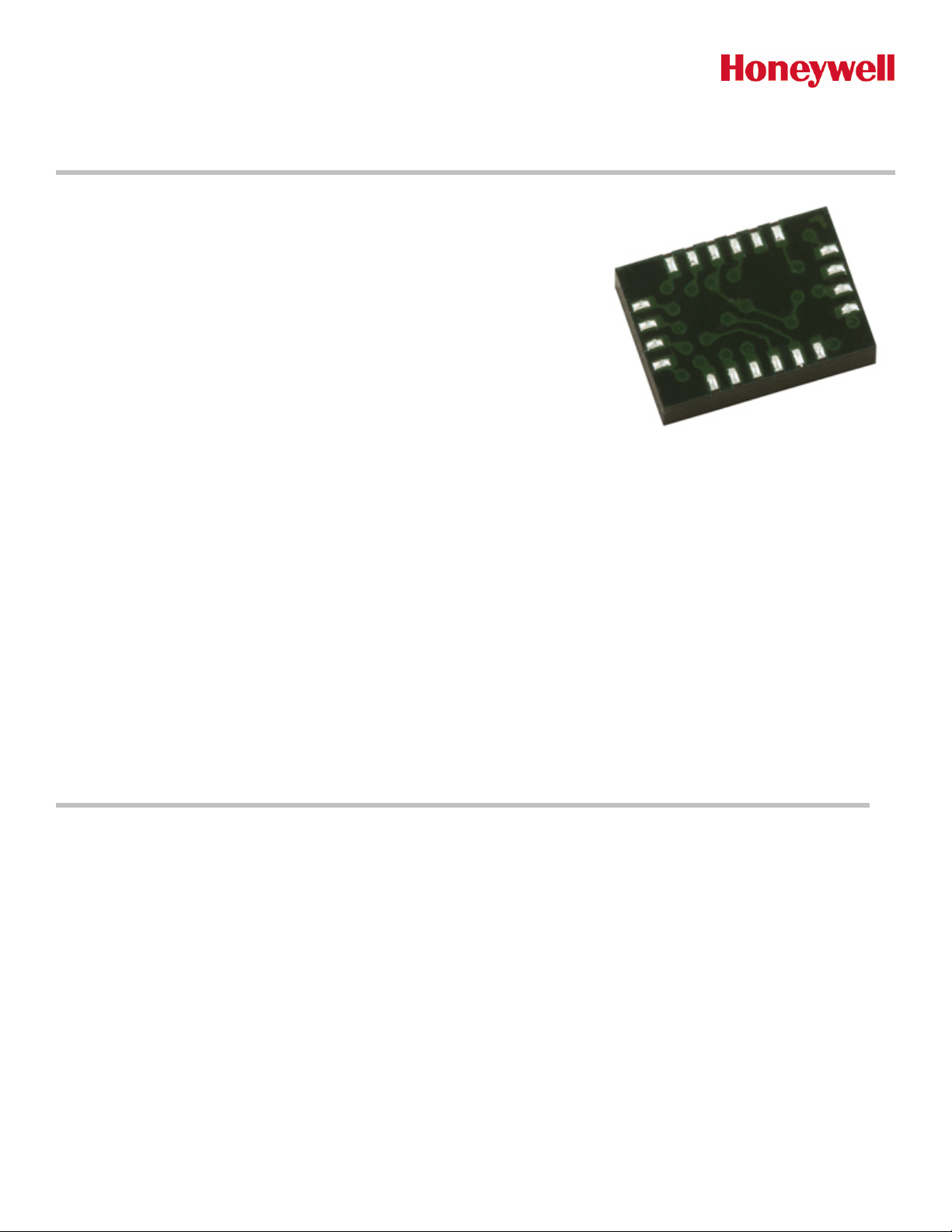
HMC6042
The Honeywell HMC6042 is a surface mount multi-chip module designed
for low field magnetic sensing such as low cost compassing and
magnetometry. The HMC6042 includes our state of the art 1042 series
magneto-resistive sensors plus a precision mixed signal ASIC containing
three sensor amplifiers and a compatible set/reset strap driver circuit for 2.4
to 3.6 volt operation. The ASIC plus sensors are surface mount packaged in
a 3.6 by 5.0 by 1.0mm LCC that can be used stand alone for very low cost
2-axis compasses, or with the HMC1041Z to complete the magnetic sensor
portion of a 3-axis, tilt compensated compass. Applications for the
HMC6042 include Consumer Electronic Compassing and Magnetometry.
The HMC6042 utilizes Honeywell’s Anisotropic Magnetoresistive (AMR) technology that provides advantages over other
magnetic sensor technologies. The sensors feature precision in-axis sensitivity and linearity, solid-state construction with
very low cross-axis sensitivity designed to measure both direction and magnitude of Earth’s magnetic fields, from tens of
micro-gauss to 6 gauss. Honeywell’s Magnetic Sensors are among the most sensitive and reliable low-field sensors in the
Advanced Information
industry.
Honeywell continues to maintain product excellence and performance by introducing innovative solid-state magnetic
sensor solutions. These are highly reliable, top performance products that are delivered when promised. Honeywell’s
magnetic sensor solutions provide real solutions you can count on.
FEATURES BENEFITS
2-Axis Magnetoresistive Sensor and
4
ASIC in a Single Package
Low Cost
4
5 x 3.6 x 1.0mm LCC Surface Mount
4
Package
Low Voltage Operations (2.4 to 3.6V)
4
Built-In Set/Reset Drive Circuit
4
Signal Processing Flexibility
4
Lead Free Package Construction
4
Wide Magnetic Field Range (+/-6 Oe)
4
Available in Tape & Reel Packaging
4
Small Size for Highly Integrated Products. Just Add a Micro-
4
Controller Interface with ADC, Plus Two External SMT Capacitors
Designed for High Volume, Cost Sensitive OEM Designs
4
Easy to Assemble & Compatible with High Speed SMT Assembly
4
Compatible for Battery Powered Applications
4
Single Logic Input for Degaussing, Thermal Drift Compensation
4
Feedback Pins for Gain and Bandwidth Shaping
4
Complies with Current Environmental Standards
4
Sensors Can Be Used in Strong Magnetic Field Environments
4
High Volume OEM Assembly
4
Page 2

HMC6042
SPECIFICATIONS
Characteristics Conditions* Min Typ Max Units
System
Sensitivity Open Loop Gain, After Set/Reset Pulses 175 275 mV/V/gauss
Zero Field Offset VDD1 = 3.0 volts 0.75 1.5 2.25 volts
Magnetic Field Range Full Scale ±1 ±2 gauss
Power Supply
Supply Voltage VDD1, VDD2 Referenced to GND 2.4 3.0 3.6 Volts
Current
Magnetic sensors
Bridge Current = 0.9mA/volt per axis
Continuous (VDD1)
Peak (0.5msec) (VDD1 + VDD2)
5.2
7.0
mA
25
Field Range Full scale (FS) – total applied field -6 +6 gauss
Sensitivity After Set/Reset Pulses 0.8 1.0 1.25 mV/V/gauss
Resolution 1 kHz bandwidth, VDD1 = 3.0 volts 0.12 milli-gauss (RMS)
Bridge Offset
Offset = (OUT+) – (OUT-)
-1.25 ±0.5 +1.25 mV/V
Field = 0 gauss after Set pulse
Cross-Axis Sensitivity
Cross field = 0.5 gauss,
±0.2% %FS/gauss
Happlied = ±3 gauss
Disturbing Field
Sensitivity starts to degrade.
20 gauss
Use S/R pulse to restore sensitivity.
Max. Exposed Field No perming effect on zero reading 10000 gauss
Sensitivity Tempco TA= -40 to 125°C, Vbridge=5V -3500 -3100 -2000 ppm/°C
Bridge Offset Tempco TA= -40 to 125°C, No Set/Reset
T
= -40 to 125°C, With Set/Reset
A
±500
±10
ppm/°C
Bridge Ohmic Tempco VDD1 = 3.0V, TA = -40 to 125°C 2100 2500 2900 ppm/°C
Linearity Error
Best fit straight line
± 1 gauss
± 3 gauss
± 6 gauss
0.17
0.42
0.80
%FS
Hysteresis Error 3 sweeps across ±3 gauss 0.15 %FS
Repeatability Error 3 sweeps across ±3 gauss 0.11 %FS
ASIC
Amplifier Gains No Feedback Connections 225 V/V
Bandwidth 10 kHz
Slew Rate 0.1
V/µsec
Gain Bainwidth Av = 250 1.0 MHz
Phase Margin Av = 250 45 deg
Output Voltage Range VDD1 = 3.0V 0.15 2.85 V
Output Current
Source
Sink
Set/Reset Strap Driver
Reservior Cap C1 Recommended Capacitor Size 2.2 4.4 10
3.6
3.6
mA
µF
Load Road Range Includes Internal 1042 S/R Strap 1.5 6 ohms
2 www.honeywell.com
Page 3
HMC6042
Characteristics Conditions* Min Typ Max Units
Internal Strap Resistance 3 6 ohms
Other
Operating Temperature Ambient -40 125 °C
Storage Temperature Ambient, unbiased -55 125 °C
Weight TBD milli-grams
* Tested at 25°C except stated otherwise.
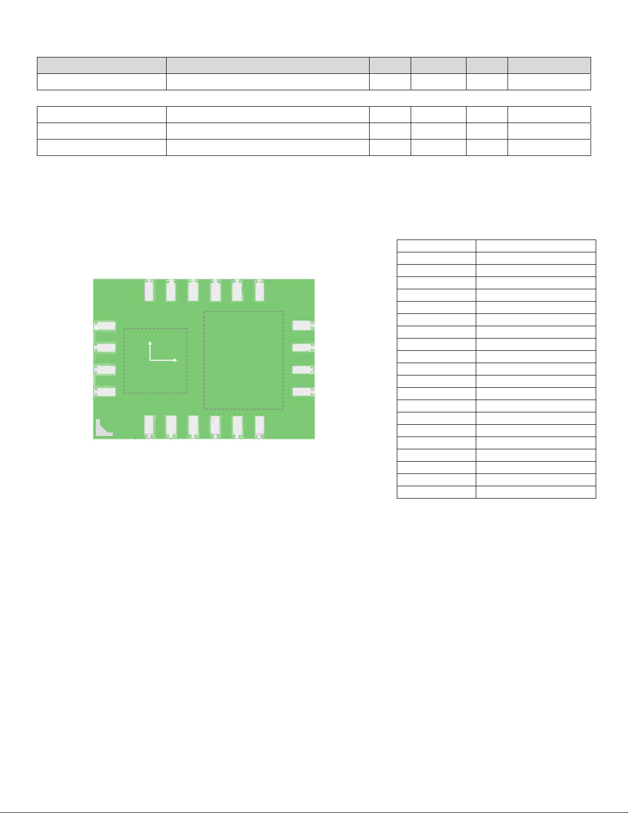
PIN CONFIGURATIONS
(Arrow indicates direction of applied field that generates a positive output voltage after a SET pulse.)
S/R-
IN Z+
S/R-
IN Z+
IN Z-
IN Z-
C1
C1
S/R C
S/R C
S/R IN
S/R IN
56 7 8910
HMC6042
HMC6042
56 7 8910
4
4
S/R+ FB Z
S/R+ FB Z
OFF-
OFF-
3
3
2
2
NC
NC
1
1
VDD1
VDD1
Y
Y
AMR DIE
AMR DIE
X
X
ASIC
ASIC
DIE
DIE
11
11
12
12
OUT Z
OUT Z
13
13
FB Y
FB Y
14
14
OUT Y
OUT Y
151617181920
OFF+
OFF+
NC
NC
VDD2
GND
VDD2
GND
OUT X
OUT X
151617181920
FB X
FB X
BOTTOM VIEW
BOTTOM VIEW
Pin Number Function
1 VDD1
2 NC
3 Offset Strap4 Set/Reset+
5 Set/Reset6 Z sensor In+
7 Z sensor In8 C1, reservoir cap
9 Set/Reset drive out
10 Set/Reset logic input
11 Z amp feedback
12 Z amp output
13 Y amp feedback
14 Y amp output
15 X amp feedback
16 X amp output
17 GND, ground return
18 VDD2
19 NC
20 Offset Strap+
www.honeywell.com 3
Page 4

HMC6042
PACKAGE OUTLINES
PACKAGE DRAWING HMC6042 (20-PIN LPCC, dimensions in millimeters)
Dimensions
D 5.00 BSC
D1 2.50 BSC
E 3.60 BSC
E1 1.50 BSC
A 0.89 1.06 1.23
Minimum Nominal Maximum
MOUNTING CONSIDERATIONS
The following is the recommend printed circuit board (PCB) footprint for the HMC6042.
PCB Pad Definition
The HMC6042 is a fine pitch LCC package with a 0.50mm pin pitch (spacing), with the pin pads defined as 0.50mm by
0.20mm in size. PCB pads are recommended to be oversized by 0.025mm from each pad for a short dimension oversize
of 0.05mm. The interior PCB pad is recommended to be 0.05mm oversized per pin with an exterior oversize of 0.20mm
for proper package centering and to permit test probing. Lead finish is SnAgCu.
Stencil Design and Solder Paste
A 4 mil stencil and 100% paste coverage is recommended for the electrical contact pads. The HMC6042 has been tested
successfully with no-clean solder paste.
Pick and Place
Placement is machine dependant and no restrictions are recommended, and have been tested with mechanical centering.
Placement force should be equivalent 1206 SMT resistors and enough force should be used to squeeze the paste out
from the package/contact pad overlap and to keep the package pin contacts vertical.
Reflow and Rework
No special profile is required for the HMC6042 and compatible with lead eutectic and lead-free solder paste reflow
profiles. Honeywell recommends the adherence to solder paste manufacturer’s guidelines. The HMC6042 may be
reworked with soldering irons, but extreme care must be taken not to overheat the copper pads from the part’s fiberglass
e = 0.5 Basic
4 www.honeywell.com
Page 5

HMC6042
substrate. Irons with a tip temperature no greater than 315°C should be used. Excessive rework risks the copper pads
pulling away into the molten solder.
SCHEMATIC DIAGRAM
HMC6042
VDD1
VDD1
GND
GND
GND
GND
AN0
AN0
AN1
AN1
AN2
AN2
Host µC
Host µC
Vss
Vss
CLK
CLK
TXD
TXD
RXD
RXD
DO0
DO0
Vdd
Vdd
VDD
VDD
SERIAL
SERIAL
I/O
I/O
AMR
AMR
AMR
AMR
VDD1
VDD1
GND
GND
IN X+
IN X+
IN X-
IN X-
IN Y+
IN Y+
IN Y-
IN Y-
HMC6042
HMC6042
G
G
G
GG
OUT X
OUT X
FB X
FB X
OUT Y
OUT Y
FB Y
FB Y
IN Z+
IN Z+
IN Z-
IN Z-
S/R+
S/R+
SET/RESET
SET/RESET
S/R-
S/R-
GND
GND
C2
C2
G
G
S/R C
S/R C
0.22µF
0.22µF
OUT Z
OUT Z
FB Z
FB Z
C1
C1
2.2µF
2.2µF
+
+
S/R IN
S/R IN
VDD2
VDD2
GND
GND
BASIC DEVICE OPERATION
The Honeywell HMC6042 magnetoresistive sensor circuit is a pair of sensor and analog support circuits to measure
magnetic fields. With power supply applied, the sensor converts any incident magnetic field in the sensitive axis direction
to a differential voltage output. In addition to the bridge circuit, the sensors have two on-chip magnetically coupled straps;
the offset strap and the set/reset strap. These straps are Honeywell patented features for incident field adjustment and
magnetic domain alignment; and eliminate the need for external coils positioned around the sensors.
The magnetoresistive sensors are made of a nickel-iron (Permalloy) thin-film deposited on a silicon wafer and patterned
as a resistive strip element. In the presence of a magnetic field, a change in the bridge resistive elements causes a
corresponding change in voltage across the bridge outputs.
www.honeywell.com 5
Page 6

HMC6042
These resistive elements are aligned together to have a common sensitive axis (indicated by arrows on the pinouts) that
will provide positive voltage change with magnetic fields increasing in the sensitive direction. Because the output only is in
proportion to the one-dimensional axis (the principle of anisotropy) and its magnitude, additional sensor bridges placed at
orthogonal directions permit accurate measurement of arbitrary field direction. The combination of sensor bridges in two
and three orthogonal axis permit applications such as compassing and magnetometry.
The offset strap allows for several modes of operation when a direct current is driven through it. These modes are: 1)
Subtraction (bucking) of an unwanted external magnetic field, 2) null-ing of the bridge offset voltage, 3) Closed loop field
cancellation, and 4) Auto-calibration of bridge gain.
The set/reset strap can be pulsed with high currents for the following benefits: 1) Enable the sensor to perform high
sensitivity measurements, 2) Flip the polarity of the bridge output voltage, and 3) Periodically used to improve linearity,
lower cross-axis effects, and temperature effects.
Offset Strap
The offset strap is a spiral of metallization that couples in the sensor element’s sensitive axis. The offset strap measures
nominally 8 ohms, and requires 10mA for each gauss of induced field. The straps will easily handle currents to buck or
boost fields through the ±6 gauss linear measurement range, but designers should note the extreme thermal heating on
the die when doing so.
With most applications, the offset strap is not utilized and can be ignored. Designers can leave one or both strap
connections (Off- and Off+) open circuited, or ground one connection node. Do not tie both strap connections together to
avoid shorted turn magnetic circuits.
Set/Reset Strap
The set/reset strap is another spiral of metallization that couples to the sensor elements easy axis (perpendicular to the
sensitive axis on the sensor die. Each set/reset strap has a nominal resistance of 5 ohms with a nominal required peak
current of 500mA for reset or set pulses. With rare exception, the set/reset strap must be used to periodically condition the
magnetic domains of the magneto-resistive elements for best and reliable performance.
A set pulse is defined as a positive pulse current entering the S/R+ strap connection. The successful result would be the
magnetic domains aligned in a forward easy-axis direction so that the sensor bridge’s polarity is a positive slope with
positive fields on the sensitive axis result in positive voltages across the bridge output connections.
A reset pulse is defined as a negative pulse current entering the S/R+ strap connection. The successful result would be
the magnetic domains aligned in a reverse easy-axis direction so that sensor bridge’s polarity is a negative slope with
positive fields on the sensitive axis result in negative voltages across the bridge output connections.
Typically a reset pulse is sent first, followed by a set pulse a few milliseconds later. By shoving the magnetic domains in
completely opposite directions, any prior magnetic disturbances are likely to be completely erased by the duet of pulses.
For simpler circuits with less critical requirements for noise and accuracy, a single polarity pulse circuit may be employed
(all sets or all resets). With these uni-polar pulses, several pulses together become close in performance to a set/reset
pulse circuit. Figure 1 shows a quick and dirty manual pulse circuit for uni-polar application of pulses to the set/reset strap.
ASIC
Within the HMC6042, the application specific integrated circuit (ASIC) performs the set/reset strap drive and sensor
amplification functions. The ASIC has its positive power supply rails broken into VDD1 and VDD2 elements to supply the
sensors/amplifiers and set/reset driver respectively. The VDD1 rail with the sensors and amplifiers combined is designed
to permit power supply duty cycling to conserve battery energy when the circuit is not used. Both the sensors and
amplifiers are designed to stabilize within 1 millisecond after power-up to permit snapshot measurements and return to
sleep status. Either PNP or P-MOSFET devices can be used to switch VDD1 off and on. To best ensure minimal energy
consumption, place any supply decoupling capacitors outside of the switch transistor, and not across the VDD1 side of the
switch.
Set/Reset Strap Driver
To permit operation from 2.4 to 3.6 volt DC supplies, and provide the required 400mA peak current spikes on the sensor
set/reset straps; both a H-bridge driver circuit and capacitive charge pump are employed. Within the H-Bridge drive circuit
several totem-pole complementary MOSFET stages are used to buffer the low voltage logic input (S/R_IN) with the last
6 www.honeywell.com
Page 7

y
HMC6042
stages composed of 400 milli-ohm switches for high efficiency switching of the set and reset currents. The logic input is
expected to be normally high with high-to-low and low-to-high transitions creating reset and set pulses respectively.
Typically, the logic low time between pulses is from a half a millisecond to hundreds of milliseconds to accommodate
reverse polarity sensor measurements as desired. See application notes AN212 and AN213 for further details on nulling
sensor bridge offsets and set/reset strap operation.
To ensure plenty of current at all temperatures, strap load values, and VDD2 supply voltages, a charge pump is designed
into the ASIC to push the reservoir capacitor C1 up to a 3.3 volt value. This pump contains its own 25MHz oscillator and is
current limited to about 1mA draw for modest but quick charges after set and reset pulse usage. When using C1 values of
2.2 to 10 microfarad, only a small amount of voltage drop occurs on C1 and is quickly recharged to its quiescent voltage.
Other than momentary charge pump or set/reset pulse operation, the current draw on VDD2 goes to zero; and can be left
on continuous power supply rails indefinitely.
The choice of C1 and C2 capacitor values is dependant on the quantity and type of sensor set/reset straps used. The
requirement for the set/reset pulse values are one to two microsecond time constant pulses, with C2 and the set/reset
strap load resistance setting the RC time constant. Stand alone, the HMC6042 requires a 0.22 to 0.47 microfarad
capacitor, and with the extra HMC1041Z sensor in parallel the values increase to 0.47 to 1.0 microfarad. C1 is typically
sized at ten times the C2 value to have minimum voltage droop as a C2 charge is extracted from C1.
Amplifiers
Three sensor amplifier sections are designed into the ASIC for the embedded HMC1042 two-axis sensors and an optional
external third axis sensor. The nominal gain of each amplifier section is about 225 V/V with all three amplifiers fairly close
in matched gains. The amplifier sections are broken into two cascaded stages with gains of 22.5 and 10 from input to
output. The second stage has a feedback pin brought out to adjust the gain from unity (output and feedback pins shorted)
to ten (output and feedback pins open). The second stage feedback resistors are nominally 10k-ohms and sections gains
can be trimmed by adding external shunt resistances. Also modest amounts of feedback capacitance can be placed
across the output and feedback pins to lower the bandwidth of the amplifiers for greater EMI immunity.
ORDERING INFORMATION
Caution
Caution
Ordering Number Product
This part is sensitive to damage
This part is sensitive to damage
HMC6042
HMC6042 T/R 1k
HMC6042 Cut Tape
Two-Axis Magnetic Sensor Circuit
Tape and Reel 1k pieces/reel
CAUTION: ESDS CAT. 1A
Cut Tape
CAUTION: ESDS CAT. 1A
This part is sensitive to damage
by electrostatic discharge. Use ESD
by electrostatic discharge. Use ESD
by electrostatic discharge. Use ESD
precautionary procedures when
precautionary procedures when
precautionary procedures when
touching, removing or inserting.
touching, removing or inserting.
touching, removing or inserting.
FIND OUT MORE
For more information on Honeywell’s Magnetic Sensors visit us online at www.magneticsensors.com or contact us at
800-323-8295 (763-954-2474 internationally).
The application circuits herein constitute typical usage and interface of Honeywell product. Honeywell does not warranty or assume liability of customerdesigned circuits derived from this description or depiction.
Honeywell reserves the right to make changes to improve reliability, function or design. Honeywell does not assume any liability arising out of the
application or use of any product or circuit described herein; neither does it convey any license under its patent rights nor the rights of others.
U.S. Patents 4,441,072, 4,533,872, 4,569,742, 4,681,812, 4,847,584 and 6,529,114 apply to the technology described
Caution
Honeywell
12001 Highway 55
Plymouth, MN 55441
Tel: 800-323-8295
www.honeywell.com/magneticsensors
www.honeywell.com 7
Form #900350
August 2007
©2007 Hone
well International Inc.
 Loading...