

Page 1
查询HMC1501供应商
SENSOR PRODUCTS
APPLICATIONS
Linear Displacement
Angular Displacement
Motor Control
Valve Position
Proximity Detection
Current Spike Detection
Linear / Angular / Rotary
Displacement Sensors
HMC1501 / HMC1512
igh resolution, low power MR sensor
capable of measuring the angle
H
Not actual size
direction of a magnetic field from a
magnet with <0.07° resolution.
Advantages of measuring field
direction versus field strength include:
insensitivity to the tempco of the
magnet, less sensitivity to shock and
vibration, and the ability to withstand
large variations in the gap between
the sensor and magnet. These
sensors may be operated on 3 volts
with bandwidth response of 0-5 MHz.
Output is typical Wheatstone bridge.
FEA TURES AND BENEFITS
No Rare Earth Magnets Unlike Hall effect devices which may require samarium cobalt or similar “rare earth”
magnets, the HMC1501 and HMC1512 can function with Alnico or ceramic type magnets.
Wide Angular Range HMC1501—Angular range of ±45° with <0.07° resolution.
HMC1512—Angular range of ±90° with <0.05° resolution.
Effective Linear Range Linear range of 8mm with two sensors mounted on two ends; range may be increased
through multiple sensor arrays operating together.
Absolute Sensing Unlike incremental “encoding” devices, sensors know the exact position and require no
indexing for proper positional output.
Non-Contact Sensing No moving parts to wear out; no dropped signals from worn tracks as in conventional
contact based rotary sensors.
Small Package Available in an 8-pin surface mount package with case dimensions (exclusive of pins), of
5mm x 4mm x 1.2mm total mounting envelope, with pins of less than 6mm square.
Large Signal Output Full Scale output range of 120mV with 5V of power supply.
Page 2
HMC1501 / HMC1512 SENSOR PRODUCTS
BridgeA
BridgeB
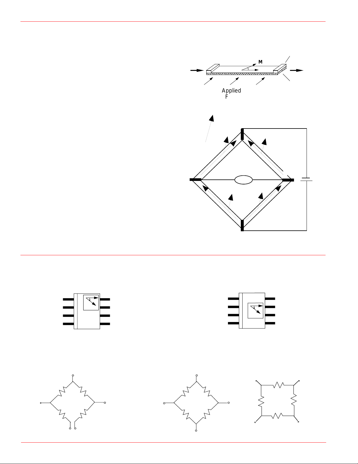
PRINCIPLES OF OPERATION
Anisotropic magnetoresistance (AMR) occurs in ferrous
materials. It is a change in resistance when a magnetic
field is applied in a thin strip of ferrous material. The magnetoresistance is a function of cos2θ where θ is the angle
between magnetization M and current flow in the thin strip.
When an applied magnetic field is larger than 80 Oe, the
magnetization aligns in the same direction of the applied
field; this is called saturation mode. In this mode, θ is the
angle between the direction of applied field and the current
flow; the MR sensor is only sensitive to the direction of
applied field.
The sensor is in the form of a Wheatstone bridge (Figure 1).
The resistance R of all four resistors is the same. The bridge
power supply V
causes current to flow through the resistors,
S
the direction as indicated in the figure for each resistor.
Both HMC1501 and HMC1512 are designed to be used in
saturation mode. HMC1501 contains one MR bridge and
HMC1512 has two identical MR bridges, coexisting on a
single die. Bridge B physically rotates 45° from bridge A.
The HMC1501 has sensor output ∆V=-V
the HMC1512 has sensor output ∆V=V
S sin (2θ) and
S
S sin (2θ) for sen-
S
sor A and sensor B output ∆VS=-VSS cos (2θ), where VS is
supply voltage, S is a constant, determined by materials.
For Honeywell sensors, S is typically 12mV/V.
Current
Flow
Applied
Field
Applied Field Direction
M
R+∆R
MM
R-∆R
θ
M
∆V
+ -
Figure 1
Metal Contact
M
Permalloy
Thin Film
(NiFe)
R-∆R
I
Vs
R+∆R
PINOUT DRAWINGS
HMC1501
OUT+ 1
•
θ
GND 1 2
3
4
Caution: Do not connect GND or Power to Pin 3,4 &6.
8 OUT7 GND 2
6
5 VBRIDGE
MR SENSOR CIRCUITS
VBRIDGE
R
OUT+
R
GND 1
GND 2
R
OUT-
R
OUT+
A
VBRIDGEB
VBRIDGEA
VBRIDGE A
R
R
GND A
OUT- A
OUT- B
R
R
HMC1512
1
2
3
4
OUT-
A
•
θ
R
8
7
6
5
R
R
GNDA
GNDB
OUT+ B
OUT+ A
VBRIDGE BOUT +B
R
OUT -BGND B
2
Page 3
HMC1501 / HMC1512 SENSOR PRODUCTS
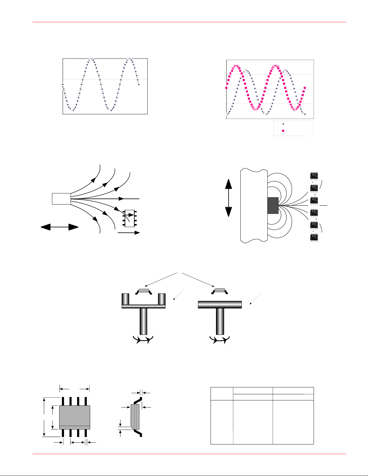
TYPICAL SENSOR OUTPUT
HMC1501 output voltage vs. magnetic field angle HMC1512 output voltage vs. magnetic field angle
60
40
20
0
-20
0 100 200 300 400
-40
-60
Sensor Output (mV)
-80
-100
Theta (degree)
APPLICATION CONFIGURATION
Proximity Position
N
S
Moving Direction
θ
100
50
0
0 100 200 300 400
-50
Sensor Output (mV)
-100
Theta (degree)
Linear Position
Valve
Actuator
Stem
N
Moving Direction
Bridge A
Bridge B
B
A
Reference
Direction
N
S
Rotating Shaft
PACKAGE DRAWING 8-Pin SOIC
D
E
H
1
•
e
h x 45°
B
Rotary Position
HMC1501/1512 MR Sensor
Magnet
S
N
A1
A
NS
Rotating Shaft
Symbol
A
A1
B
D
E
e
H
h
~0.5 to -1.5 inches
Magnet
Millimeters Inches
Min
1.371
0.101
0.355
4.800
3.810
1.270 ref
5.816
0.381
Max
1.728
0.249
0.483
4.979
3.988
.050 ref
6.198
0.762
Min
.054
.004
.014
.189
.150
.229
.015
Max
.068
.010
.019
.196
.157
.244
.030
3
Page 4

HMC1501 / HMC1512 SENSOR PRODUCTS
SPECIFICATIONS
scitsiretcarahC*snoitidnoC1051CMH
xaMpyTniM
2151CMH
xaMpyTniM
stinU
ylppusegdirBDNGotdecnereferegdirbV15521552V
ecnatsiseregdirBAm1—tnerrucegdirB455.60.21.28.2KΩ
egnarelgnA>
dleifnoitarutaS54-54+09-09+ged
,eO08dleif,V5=egdirbV
ytivitisneS
gnissorcorez@)1(
degareva,gnissorcoreZ@)2(
1.2
8.1
1.2
8.1
°/Vm
°54foegnarehtni
egatloVkaep-ot-kaePeO08=dleif,V5=egdirbV001021041001021041Vm
tesffoegdirB
,eO08dleiF θ AegdirB°0=
7-37
BegdirB
0
4-
5.2
0
5
1
V/Vm
dleifnoitarutaSSF%30.0<ytilibataepeR0808G
htdiwdnaBlangiscitengaM0505zHM
noituloseRV5=egdirbV,zH01=htdiwdnaB70.050.0°
rorresiseretsyH
egdirB Ω ocpmetT
ocpmetytivitisneS
A
T
dleifcitengaM>
V5=egdirbV
A
V5=egdirbV
,dleifnoitarutas
03
2-
01x7.1
03
2-
01x7.1
C°521+otC°04-=82.082.0C°/%
C°521+otC°04-=
23.0-23.0-C°/%
Vµ
ged
ocpmettesffoegdirBT
A
C°521+otC°04-=10.0-10.0-SF,C°/%
ytisneDesioNV5=egdirbV,zH1taesioN00107zHVn
noitpmusnoCrewoPV5=egdirbV532Wm
*Tested at 25°C except stated otherwise.
Sensitivity tempco Cs =St-So = -0.32%/°C
Where S
Power consumption P =
Where V = Bridge supply voltage
Honeywell reserves the right to make changes to any products or technology herein to improve reliability, function or design. Honeywell does not assume any liability
arising out of the application or use of any product or circuit described herein; neither does it convey any license under its patent rights nor the rights of others.
o = sensitivity at zero temperature
t = temperature in the range -40°C to 125°C
S
t = sensitivity at temperature t
R = Bridge resistance
So*t
V
R
2
Offset tempco Co = Vo (t) - Vo (o) = -0.01%/°C
Where V
1 KA/m = 12.5 Gauss
1 Tesla = 104 Gauss
o (o) = bridge offset at zero temperature
VP-P = peak-to-peak voltage
t = temperature in the range -40°C to 125°C
V
o (t) = offset at temperature t
VP-P*t
Solid State Electronics Center
12001 State Highway 55
Plymouth, MN 55441
1-800-323-8295
http://www.ssec.honeywell.com
900246 8-00 Rev. B
4
 Loading...