

HMC1051/HMC1052/HMC1053
1, 2 AND 3-AXIS MAGNETIC SENSORS
Features
x Miniature Surface-Mount Packages
x Wide Field Range of ± 6 Gauss
x 1.0 mV/V/gauss Sensitivity
x Low Power Operation Down to 1.8V
x Patented On-chip Set/Reset and Offset Straps
Product Description
The Honeywell HMC1051, HMC1052 and HMC1053
are high performance magnetoresistive sensor designs
on a single chip (HMC1051, HMC1052) or two chips
(HMC1053). The advantages of these patented chips
include orthogonal two-axis sensing (HMC1052), ultra
small size and low cost in miniature surface mount
packages.
SENSOR PRODUCTS
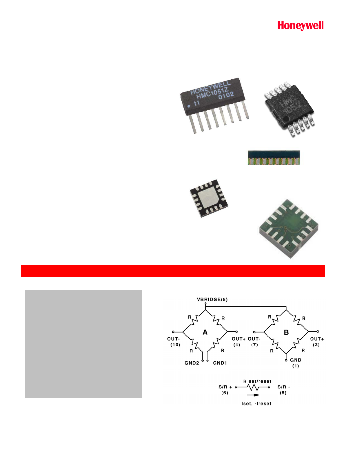
Each of the magneto-resistive sensors are configured
as a 4-element wheatstone bridge to convert magnetic
fields to differential output voltages. Capable of sensing
fields down to 120 micro-gauss, these sensors offer a
compact, high sensitivity and highly reliable solution for
low field magnetic sensing.
APPLICATIONS
x Compassing
x Navigation Systems
x Attitude Reference
x Traffic Detection
x Medical Devices
HMC1052 Circuit Diagram
(3)(9) (3)(9)
x Position Sensing
Solid State Electronics Center • www.magneticsensors.com • (800) 323-8295 • Page 1

HMC1051/HMC1052/HMC1053
SENSOR PRODUCTS
SPECIFICATIONS
Characteristics Conditions* Min Typ Max Units
Bridge Elements
Supply Vbridge referenced to GND 1.8 3.0 20 Volts
Resistance Bridge current = 10mA 800 1000 1500 ohms
Operating
Temperature
Storage
Temperature
Humidity Tested at 85°C 85 %
Field Range Full scale (FS) – total applied field -6 +6 gauss
Linearity Error Best fit straight line
Hysteresis Error 3 sweeps across ±3 gauss 0.06 %FS
Repeatability Error 3 sweeps across ±3 gauss 0.1 %FS
Bridge Offset Offset = (OUT+) – (OUT-)
Field = 0 gauss after Set pulse
Sensitivity Set/Reset Current = 0.5A 0.8 1.0 1.2 mV/V/gauss
Noise Density @ 1kHz, Vbridge=5V 50 nV/sqrt Hz
Resolution 50Hz Bandwidth, Vbridge=5V 120
Bandwidth Magnetic signal (lower limit = DC) 5 MHz
Disturbing Field Sensitivity starts to degrade.
Use S/R pulse to restore sensitivity.
Sensitivity
Tempco
Bridge Offset
Tempco
Bridge Ohmic
Tempco
Cross-Axis Effect Cross field = 1 gauss, Happlied = ±1 gauss ±3 %FS
Max. Exposed
Field
Sensitivity Ratio of
X,Y Sensors
(HMC1052 Only)
X,Y sensor
Orthogonality
(HMC1052)
* Tested at 25°C except stated otherwise.
TA= -40 to 125°C, Vbridge=5V
T
= -40 to 125°C, Ibridge=5mA
A
TA= -40 to 125°C, No Set/Reset
T
= -40 to 125°C, With Set/Reset
A
Vbridge=5V, TA= -40 to 125°C 2100 2500 2900 ppm/°C
No perming effect on zero reading 10000 gauss
Sensitive direction in X and Y sensors 0.01 degree
Ambient -40 125 °C
Ambient, unbiased -55 150 °C
± 1 gauss
± 3 gauss
± 6 gauss
-1.25 ±0.5 +1.25 mV/V
20 gauss
-3000 -2700
TA= -40 to 125°C 95 100 105 %
0.1
0.5
1.8
-600
±500
±10
%FS
Pgauss
-2400 ppm/°C
ppm/°C
Solid State Electronics Center • www.magneticsensors.com • (800) 323-8295 • Page 2
HMC1051/HMC1052/HMC1053
SENSOR PRODUCTS
SPECIFICATIONS
Characteristics Conditions* Min Typ Max Units
Set/Reset Strap
Resistance Measured from S/R+ to S/R- 3 4.5 6 ohms
Current 0.1% duty cycle, or less,
2Psec current pulse
Resistance
TA= -40 to 125°C 3300 3700 4100 ppm/°C
Tempco
Offset Straps
Resistance Measured from OFFSET+ to OFFSET- 12 15 18 ohms
Offset
Constant
Resistance
Field applied in sensitive direction
DC Current
TA= -40 to 125°C 3500 3900 4300 ppm/°C
Tempco
* Tested at 25°C except stated otherwise.
0.4 0.5 4 Amp
10 mA/gauss
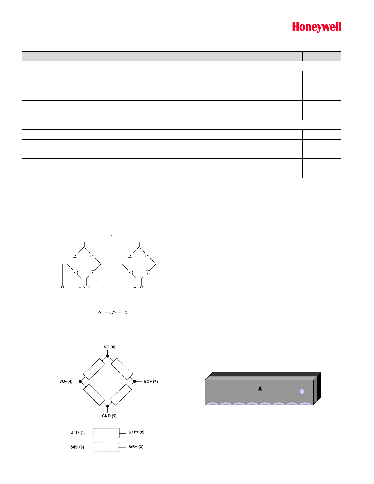
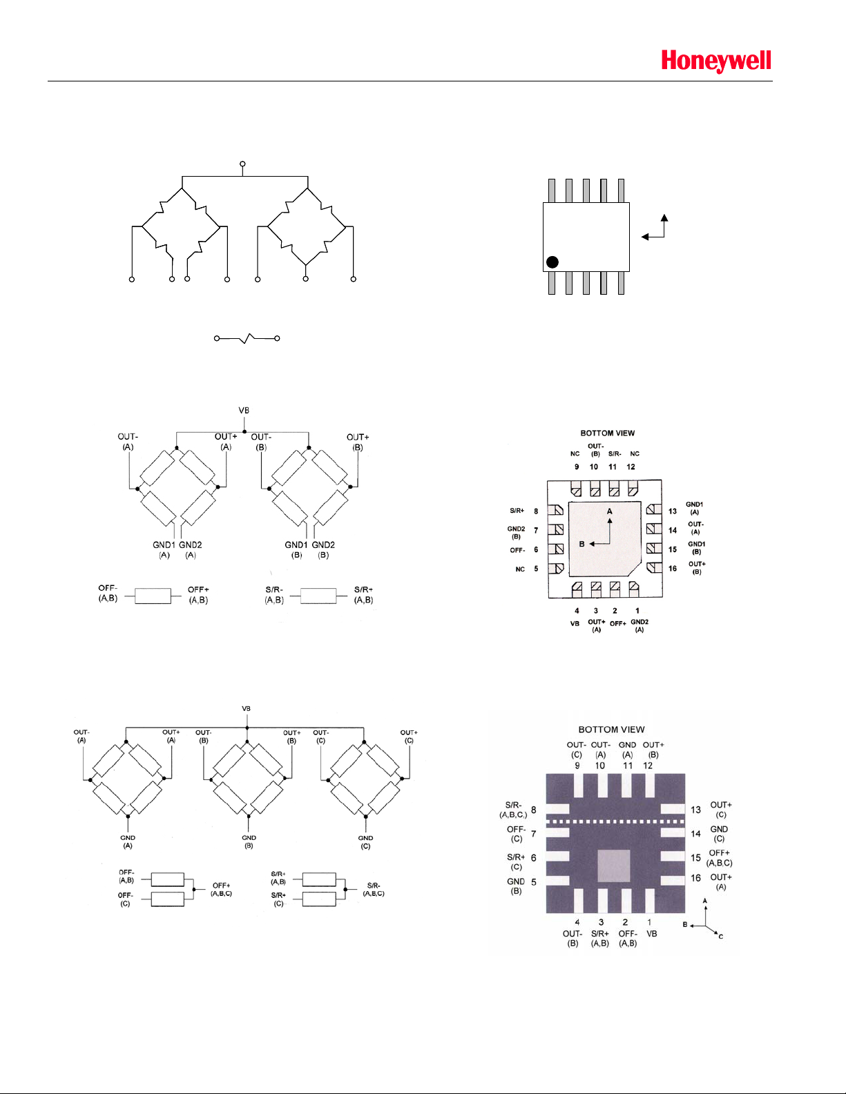
PIN CONFIGURATIONS (Arrow indicates direction of applied field that generates a positive
output voltage after a SET pulse.)
HMC1051
Vcc
(3)
HMC1051Z Pinout
HMC1051ZL
Vo+(A)
(2)
HMC1051
BRIDGE A BRIDGE B
GND Plane
(4)
S/R+
Vo-(A)
(6)
(8)
Set/Reset Strap
GND1(B)
(1)
S/R-
(7)
GND2(B)
HONEYWELL
HMC1051Z
12345678
(5)
HMC1051ZL Pinout
12345678
12345678
12345678
OFF-S/R+S/R-VO-GNDOFF+VO+VB
OFF-S/R+S/R-VO-GNDOFF+VO+VB
OFF-S/R+S/R-VO-GNDOFF+VO+VB
Solid State Electronics Center • www.magneticsensors.com • (800) 323-8295 • Page 3
HMC1051/HMC1052/HMC1053
HMC1052
SENSOR PRODUCTS
HMC1052L
Vcc
Vcc
(5)
(5)
HMC1052
HMC1052
BRIDGE A BRIDGE B
BRIDGE A BRIDGE B
GND2
OUT-
OUT-
(10)
(10)
GND2
(9)
(9)
GND1
GND1
(3)
(3)
S/R+
S/R+
OUT+
OUT+
(6)
(6)
(4)
(4)
Set/Reset Strap
Set/Reset Strap
OUT-
OUT-
(7)
(7)
S/R-
S/R-
(8)
(8)
GND
GND
(1)
(1)
OUT+
OUT+
(2)
(2)
HMC1052 Pinout
678910
HMC
A
1052
12345
HMC1052L Pinout
B
HMC1053
Solid State Electronics Center • www.magneticsensors.com • (800) 323-8295 • Page 4
HMC1053 Pinout
 Loading...