

Page 1
查询HMC1051供应商
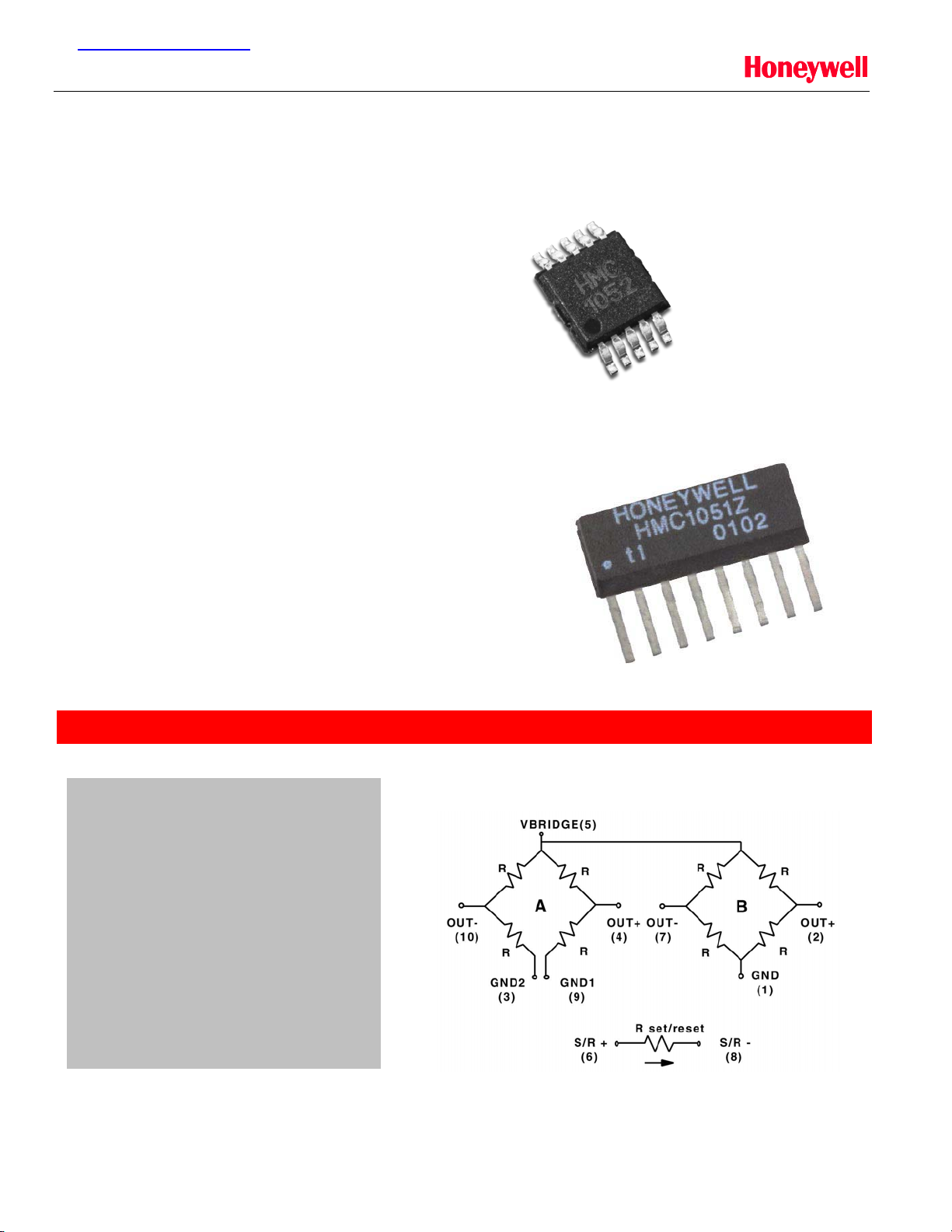
HMC1051 / HMC1052
1 AND 2-AXIS MAGNETIC SENSORS
Features
· Small 8-Pin SIP or 10-Pin MSOP Packages
· Two AMR Bridges in One Package
· Wide Field Range of +/- 6 Gauss
· 1.0 mV/V/gauss Sensitivity
· High Accuracy Compassing (Error <0.01°)
· Low Power Operation Down to 1.8V
· Patented On-chip Set/Reset Straps
Product Description
The Honeywell HMC1051Z and HMC1052 are high
performance magnetoresistive sensor designs on a
single chip. The advantages of these patented chips
include perfectly orthogonal two-axis sensing
(HMC1052), ultra small size and low power capability in
miniature surface mount packages.
SENSOR PRODUCTS
Each of the magnetoresistive sensors are configured
as a 4-element wheatstone bridge to convert magnetic
fields to differential output voltages. Capable of sensing
fields below 0.1 milligauss, these sensors offer a
compact, low cost, high sensitivity and highly reliable
solution for low field magnetic sensing.
APPLICATIONS
HMC1052 Circuit Diagram
· Compassing
· Navigation Systems
· Attitude Reference
· Traffic Detection
· Medical Devices
· Position Sensing
Web Sites: www.magneticsensors.com Honeywell
Email: ssec.customer.service@honeywell.com 12001 State Highway 55
2001 HMC1051/1052 Published Jul 2001 Page 1 1-800-323-8295
www.ssec.honeywell.com Solid State Electronics Center
Plymouth, Minnesota 55441-4799
Page 2

HMC1051 / HMC1052
SENSOR PRODUCTS
SPECIFICATIONS
Characteristics Conditions* Min Typ Max Units
Bridge Elements
Supply Vbridge referenced to GND 1.8 2.5 20 Volts
Resistance Bridge current = 1mA 800 1000 1500 ohms
Field Range Full scale (FS) – total applied field -6 +6 gauss
Sensitivity Set/Reset Current = 0.5A 0.8 1.0 1.2 mV/V/gauss
Bridge Offset Offset = (OUT+) – (OUT-)
Field = 0 gauss after Set pulse
Bandwidth Magnetic signal (lower limit = DC) 5 MHz
Noise Density @ 1kHz, Vbridge=5V 50 nV/sqrt Hz
Resolution 50Hz Bandwidth, Vbridge=5V 120
Disturbing Field Sensitivity starts to degrade.
Use S/R pulse to restore sensitivity.
Max. Exposed
No perming effect on zero reading 10000 gauss
Field
Operating
Ambient -40 125 °C
Temperature
Storage
Ambient, unbiased -55 150 °C
Temperature
Sensitivity
Tempco
Bridge Offset
Tempco
Bridge Ohmic
TA=-40 to 125°C, Vbridge=5V
T
=-40 to 125°C, Ibridge=5mA
A
TA=-40 to 125°C, No Set/Reset
T
=-40 to 125°C, With Set/Reset
A
Vbridge=5V, TA=-40 to 125°C 2100 2500 2900 ppm/°C
Tempco
Sensitivity Ratio of
TA=-40 to 125°C 99 101 103 %
X,Y Sensors
(HMC1052 Only)
X,Y sensor
Sensitive direction in X and Y sensors 0.01 degree
Orthogonality
(HMC1052)
Linearity Error Best fit straight line
+/- 1 gauss
+/- 3 gauss
+/- 6 gauss
Hysteresis Error 3 sweeps across +/-3 gauss 0.06 %FS
Repeatability Error 3 sweeps across +/-3 gauss 0.1 %FS
* Tested at 25°C except stated otherwise.
-2.5 +/-1 +2.5 mV/V
mgauss
20 gauss
-3200 -3000
-2800 ppm/°C
-600
+/-500
ppm/°C
+/-10
0.1
0.5
%FS
1.8
Web Sites: www.magneticsensors.com Honeywell
Email: ssec.customer.service@honeywell.com 12001 State Highway 55
2001 HMC1051/1052 Published Jul 2001 Page 2 1-800-323-8295
www.ssec.honeywell.com Solid State Electronics Center
Plymouth, Minnesota 55441-4799
Page 3
HMC1051 / HMC1052
SENSOR PRODUCTS
SPECIFICATIONS
Characteristics Conditions* Min Typ Max Units
Set/Reset Strap
Resistance Measured from S/R+ to S/R- 3 4 5 ohms
Current 0.1% duty cycle, or less,
2msec current pulse
Resistance
TA=-40 to 125°C 3700 ppm/°C
Tempco
Offset Straps
(available on die)
Resistance Measured from OFFSET+ to OFFSET- 12 15 18 ohms
Offset
Constant
Resistance
Field applied in sensitive direction
DC Current
TA=-40 to 125°C 3900 ppm/°C
Tempco
* Tested at 25°C except stated otherwise.
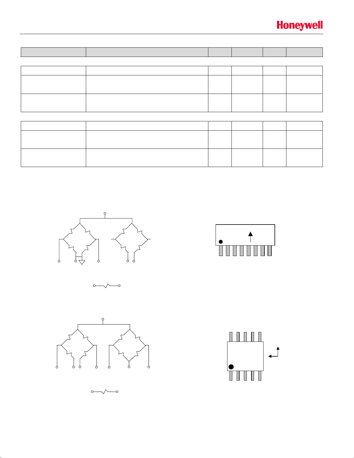
Pin Configurations (Arrow indicates direction of applied field that generates a positive output voltage after a SET pulse.)
HMC1051
Vcc
(3)
0.4 0.5 4 Amp
10 mA/gauss
HMC1051Z Pinout
HMC1052
HMC1051
BRIDGE A BRIDGE B
Vo+(A)
OUT-
GND Plane
(2)
BRIDGE A BRIDGE B
GND2
(3)
(10)
(4)
GND1
(9)
S/R+
S/R+
(6)
(6)
Vo-(A)
(8)
Set/Reset Strap
Vcc
(5)
HMC1052
OUT+
(4)
Set/Reset Strap
OUT-
(7)
GND1(B)
(1)
S/R-
(7)
GND
(1)
S/R-
(8)
GND2(B)
(5)
OUT+
(2)
HONEYWELL
HMC1051Z
12345678
HMC1052 Pinout
678910
HMC
1052
12345
B
A
Web Sites: www.magneticsensors.com Honeywell
www.ssec.honeywell.com Solid State Electronics Center
Email: ssec.customer.service@honeywell.com 12001 State Highway 55
Plymouth, Minnesota 55441-4799
2001 HMC1051/1052 Published Jul 2001 Page 3 1-800-323-8295
Page 4

HMC1051 / HMC1052
_
f
f
f
_
SENSOR PRODUCTS
Basic Device Operation
The HMC1051 and HMC1052 are single-axis and two-axis linear magnetic sensors designed as a Wheatstone
bridges formed by a magnetoresistive metal film. With the power supply applied to the bridge, the sensors converts
any incident magnetic field in the sensitive direction to a balanced voltage output. The magnetoresistive sensors are
made of a nickel-iron (Permalloy) thin-film deposited on a silicon wafer in pattern of resistive strips. In the presence of
a magnetic field, a change in the bridge resistive elements causes a corresponding change in voltage across the
bridge outputs.
In addition to the bridge circuits, the sensors each have two on-chip magnetically coupled straps; the Offset Strap and
the Set/Reset Strap. The patented straps eliminate the need for external coils surrounding the bridge elements. The
offset strap (available on bare die only) allows for several modes of operation when a direct current is driven through
it. These modes are: 1) Subtraction of an unwanted magnetic field, 2) Zero-ing of the bridge offset voltage, 3) Closed
loop field cancellation, and 4) Auto-calibration of bridge gain. The set/reset strap can be pulsed with high currents for
the following benefits: 1) Enable the sensor to perform high sensitivity measurements, 2) Flip the polarity of the bridge
output voltage, and 3) Periodically used to improve linearity, lower cross-axis effects, and temperature effects.
Application Notes
Low Cost 2-Axis Compass
Very high precision measurements can be made using the HMC1051 and HMC1052 sensors when interfaced with
low noise amplifiers and 12 to 16-bit Analog-to-Digital (A/D) converters. For lower resolution (1°) or low cost compass
applications, 8 or 10-bit A/D converters may be used with general purpose operational amplifiers. Figure 1 shows a
typical 2-axis compassing application using readily available off-the-shelf components.
The basic principle of two-axis compassing is to orient the sensor bridge element horizontal to the ground
(perpendicular to the gravitational field) and to measure the X and Y analog voltages. With the amplified sensor bridge
voltages near-simultaneously converted (measured) to their digital equivalents, the arc-tangent Y/X can be computed
to derive the heading information. See the application notes on compassing at Honeywell Magnetic Sensors website
(www.magneticsensors.com) for basic principles and detailed application information.
Figure 1
5.00k
5.00k
5.00k
5.00k
.1uf
1nf
500k
Vre
1nf
500k
Vre
(2) IRF7507
LMV358
/2
LMV358
/2
U4
U5
500k
500k
U2
set/reset
set/reset
1
0
U3
MAX1118
Vre
enable
data_out
clk
in
Vcc
2.5 to 3.6v
U1
HMC1052
set/reset
offset
Web Sites: www.magneticsensors.com Honeywell
Email: ssec.customer.service@honeywell.com 12001 State Highway 55
2001 HMC1051/1052 Published Jul 2001 Page 4 1-800-323-8295
www.ssec.honeywell.com Solid State Electronics Center
Plymouth, Minnesota 55441-4799
Page 5

HMC1051 / HMC1052
SENSOR PRODUCTS
Set/Reset Circuit Notes
The set/reset circuit using the IRF7507 dual complementary MOSFETs is shown in Figure 2 with more detail in its Hbridge driven configuration. This configuration is used primarily in battery operated applications were the 0.5 ampere
nominal set/reset pulsed currents are best obtained under low voltage conditions. For operation at normal 3.3 or 5
volt logic levels, a single complementary MOSFET pair can be used in a single ended circuit shown in Figure 3.
Other complementary MOSFET pairs can be used with the caution that the chosen devices should have less than
0.5 ohms ON resistance and be able to handle the needed supply voltages and set/reset currents. Note that even a
1Hz rate of set/reset function draws an average current of less than 2 microamperes.
Figure 2
1mf
Vsr
+
S
-
200W
IRF7509(P)
Vcc
Rset/reset
.1mf
Vsr
IRF7509(P)
S
4W
D
D
S
IRF7509(N)
D
D
S
G
G
G
G
IRF7509(N)
set/reset
_set/reset
Rset/reset
Figure 3
4W
.1mf
1mf
Vsr
+
S
-
D
D
S
IRF7509(P)
G
G
IRF7509(N)
200W
Vcc
set/reset
Magnetic Field Detection
For simple magnetic field sensing applications such Magnetic Anomaly Detectors (MADs) and Magnetometers, a
similar circuit to the compass application can be implemented. In the example circuit in Figure 4, a HMC1051Z
sensor bridge is used with a low voltage capable dual op-amp to detect sufficient intensity of a magnetic field. Uses
of the circuit include ferrous object detection such as vehicle detection, a “sniffer” for moderate currents in nearby
conductors, and magnetic proximity switching. By using two circuits with a HMC1052, a more omni-directional
sensing pattern can implemented. There is nothing special in choosing the resistors for the differential op-amp gain
stages other than having like values (e.g. the two 5kW and the 500kW resistors) matched at 1% tolerance or better to
reject common-mode interference signals (EMI, RFI). The ratio of the 500kW/5kW resistors sets the stage gain and
can be optimized for a specific purpose. The choice of the 5kW value sets impedance loading seen by the sensor
bridge network and should be about 4 kilo-ohms or higher for best voltage transfer or matching.
Web Sites: www.magneticsensors.com Honeywell
Email: ssec.customer.service@honeywell.com 12001 State Highway 55
2001 HMC1051/1052 Published Jul 2001 Page 5 1-800-323-8295
www.ssec.honeywell.com Solid State Electronics Center
Plymouth, Minnesota 55441-4799
Page 6

HMC1051 / HMC1052
SENSOR PRODUCTS
Vcc
5.0v
U1
HMC1051
set/reset
offset
Figure 4
5.00k
5.00k
Low ESR Tantalum
*
1mf*
FMMT717
.1uf
FMMT617
500k
+-
.1mf
Vcc/2
Vcc
-
TLC072
+
200W
10kW
10kW
500k
U2
0.1mf
0.1mf
10kW
set/reset
Vcc
10kW pot
Threshold Set
-
+
TLC072
output
LED
RLED
RS
Alternating or Direct Current Sensing
The HMC1051 and HMC1052 sensors can be utilized in a novel way for moderate to high current sensing
applications using a nearby external conductor providing the sensed magnetic field to the bridge. Figure 5 shows a
HMC1051Z used as a current sensor with thermistor element performing a temperature compensation function for
greater accuracy over a wide range of operational temps. Selection of the temperature compensation (tempco)
resistors used depends on the thermistor chosen and is dependant on the thermistor’s %/°C shift of resistance. For
best op-amp compatibility, the thermistor resistance should be above about 1000 ohms. The use of a 9-volt alkaline
battery supply permits fairly common operational amplifiers such as the 4558 types to be used. Note that the circuit
must be calibrated based on the final displacement of the sensed conductor to the measuring bridge. Typically, an
optimally oriented measurement conductor can be placed about one centimeter away from the bridge and have
reasonable capability of measuring from tens of milliamperes to beyond 20 amperes of alternating or direct currents.
See application note AN-209 for the basic principles of current sensing using AMR bridges.
tempco
R
1mf*
+-
Si1553DL
b
U2
Vcc =9Vdc
network
200W
U3
standoff distance
Vcc = 9Vdc
I
ac
I
dc
set/reset
U1
HMC1051
offset
Figure 5
5.00k
5.00k
.1mf
-
RC4558
+
500k
Vcc/2 ~ +4.5Vdc
*
Low ESR Tantalum
.1uf
500k
-
RC4458
+
R
a
R
th
output
set/reset
Conductor to be
Current Measured
Web Sites: www.magneticsensors.com Honeywell
www.ssec.honeywell.com Solid State Electronics Center
Email: ssec.customer.service@honeywell.com 12001 State Highway 55
Plymouth, Minnesota 55441-4799
2001 HMC1051/1052 Published Jul 2001 Page 6 1-800-323-8295
Page 7

HMC1051 / HMC1052
A
AN0AN1AN2A
SENSOR PRODUCTS
Three Axis Compassing with Tilt Compensation
For full three-axis compassing, the circuit depicted in Figure 6 shows both a HMC1051Z and a HMC1052 used for
sensing the magnetic field in three axes. A two-axis accelerometer is also shown to provide pitch and roll (tilt)
sensing to correct the three-axis data into to the corrected two-axis heading. The accelerometer can be substituted
with a fluidic 2-axis tilt sensor if desired. For lower voltage operation with Lithium battery supplies (2.5 to 3.6Vdc), the
Set/Reset circuit should be upgraded from a single IRF7507 to the dual IRF7507 implementation to permit a
minimum 1.0 ampere pulse (0.5 ampere per set/reset strap resistance) to both the HMC1052 and HMC1051 sensors.
Vcc
3.3 to 5.0v
Vcc
set/reset
offset
set/reset
U1
HMC1052
U2
Figure 6
5.00k
5.00k
5.00k
5.00k
.1uf
500k
500k
IRF7507
1nf
Vcc/2
1nf
Vcc/2
.1mf
LMV324
U3
LMV324
U4
500k
500k
500k
Vcc
Two-axis
accelerometer
Vcc
set/reset
U5
N3Vcc/2
DO0
U6
m
C
with
Multiplexed
/D Conv.
5.00k
5.00k
500k
HMC1051
-
+
Vcc/2
LMV324
xout
yout
DI0
DI1
Duty Cycling for Lower Energy Consumption
For battery powered and other applications needing limited energy consumption, the sensor bridge and support
electronics can be switched “off” between magnetic field measurements. The HMC1051Z and HMC1052 are very low
capacitance (Bandwidth > 5MHz) sensor bridges and can stabilize typically before the support electronics can. Also
minimizing the quantity of set/reset pulses will save energy too. Figure 7 shows a simple supply switching circuit that
can be microprocessor controlled to duty cycle (toggle) the electronics in moderate current (<25mA) applications.
Web Sites: www.magneticsensors.com Honeywell
Email: ssec.customer.service@honeywell.com 12001 State Highway 55
2001 HMC1051/1052 Published Jul 2001 Page 7 1-800-323-8295
www.ssec.honeywell.com Solid State Electronics Center
Plymouth, Minnesota 55441-4799
Page 8

HMC1051 / HMC1052
To Sensor Circuits
Figure 7
MMBT2907ALT1
0.01mf
Vcc
SENSOR PRODUCTS
Vcc
+
10mf
-
Gnd
* Used when Vcc = 5.0 volts, jumper
when using Vcc = 3.3 volts or less.
PACKAGE DRAWING 8-PIN SIP
*MMBD7001LT1
Symbol Millimeters
Symbol Millimeters
10kW
A1
D
E
H
A
A1
B
D
E1
e
E
L1
mC
Off
On
Min Max
A
1.371 1.728
0.101 0.249
B
0.355 0.483
9.829 11.253
3.810 3.988
e
1.270 ref
6.850 7.300
h
0.381 0.762
Min Max
- 1.10
0.05 0.15
0.15 0.30
2.90 3.10
2.90 3.10
0.50 BSC
4.75 5.05
0.95 BSC
toggle
Inches x 10E-3
Min Max
54 68
4 10
14 19
387 443
150 157
50 ref
270 287
15 30
Inches x 10E-3
Min Max
-43
2.0 5.9
5.9 11.8
114 122
114 122
2.0 BSC
187 199
37.4
Ordering Information
Ordering Number Product
HMC1051Z One Axis Magnetic Sensor – SIP8 Package
HMC1052 Two Axis Magnetic Sensors – MSOP8
Honeywell reserves the right to make changes to improve reliability, function or design. Honeywell does not assume
any liability arising out of the application or use of any product or circuit described herein; neither does it convey any
license under its patent rights nor the rights of others.
Web Sites: www.magneticsensors.com Honeywell
Email: ssec.customer.service@honeywell.com 12001 State Highway 55
2001 HMC1051/1052 Published Jul 2001 Page 8 1-800-323-8295
www.ssec.honeywell.com Solid State Electronics Center
Plymouth, Minnesota 55441-4799
 Loading...