

Page 1
HM700A1000
ELECTRODE STEAM HUMIDIFIER
Tools Needed
— Screwdriver
—Wrench
— Pliers
— Shut-off water valve
— Water line (LDPE or Copper)
Humidifier Configuration
The HM700 is configured at the factory to operate under most
conditions without the need to change its configuration.
NOTE: Because the humidifier is factory configured for
INSTALLATION INSTRUCTIONS
optimal performance, Honeywell strongly
discourages changes to the jumpers or the
potentiometer; doing so will void the warranty
and could damage the humidifier. Contact
Honeywell Customer Care for further
information.
INTRODUCTION
The HM700 is the most advanced residential steam humidifier
available and provides steady and reliable humidification for a
home. The humidifier is designed for connection to a steam
distributor installed in a supply air duct for humidity on
demand.
IMPORTANT
Read and save these instructions. This guide should
be kept by the installer, and the Homeowner’s Guide
should be left with the equipment owner.
Included in the Box
— Steam Humidifier (HM700)
— Distribution Remote Mount Kit (HM700ADISTKIT)
— HumidiPRO Humidistat (H6062A1000)
— Steam Cylinder (one HM700ACYL2 included)
— Rubber drain hose
— Installation Instructions, Homeowner’s Guide and
Quick Start Guide
Table 1. Specifications.
Steam
Output
Part Number Volts
HM700A1000
110/120 11 1.4
220/240 22 2.8
GPD KW Amps Phase
12.0 1 15 A CYL2
Before Installation
1. Ensure that available voltage and phase corresponds
with humidifier voltage and phase as indicated on
humidifier’s specification label.
2. Ensure that the dedicated external fuse disconnect is of
sufficient size to handle the rated amps as indicated on
the specification label. Refer to local codes.
3. Ensure sufficient clearances will be available as
described in the Location section on page 5.
4. Ensure steam lines can be routed to duct distributor as
described in Steam Lines and Condensate Return
Instructions on page 8.
Dimensions
in inches
(L x W x H)
11.5 x 6.75 x 21.5
Max Ext
Fuse
Standard
Cylinder
Net/Full
Weight
lbs. (kg)
15 / 20
(7.0 / 9.5)
33-00118EFS-01
Page 2
HM700A1000
CAUTION
CAUTION
CAUTION
CAUTION
CAUTION
M35758
Golden Valley Minnesota 55422
MADE IN CANADA
MODEL:
VOLTS 1:
KW:
HM700A1000
S/N:
XXXXXXX
110-120
PHASE:
1
HZ:
60
1.4
DATE:
XXXXXXXXX
2583297A
220-240
VOLTS 2:
F.L.A: GPD:
12.0
F.L.A: GPD:
12.0
2.9
KW:
Auto-Adaptive
11
22
1
LISTED 205X
HUMIDIFIER
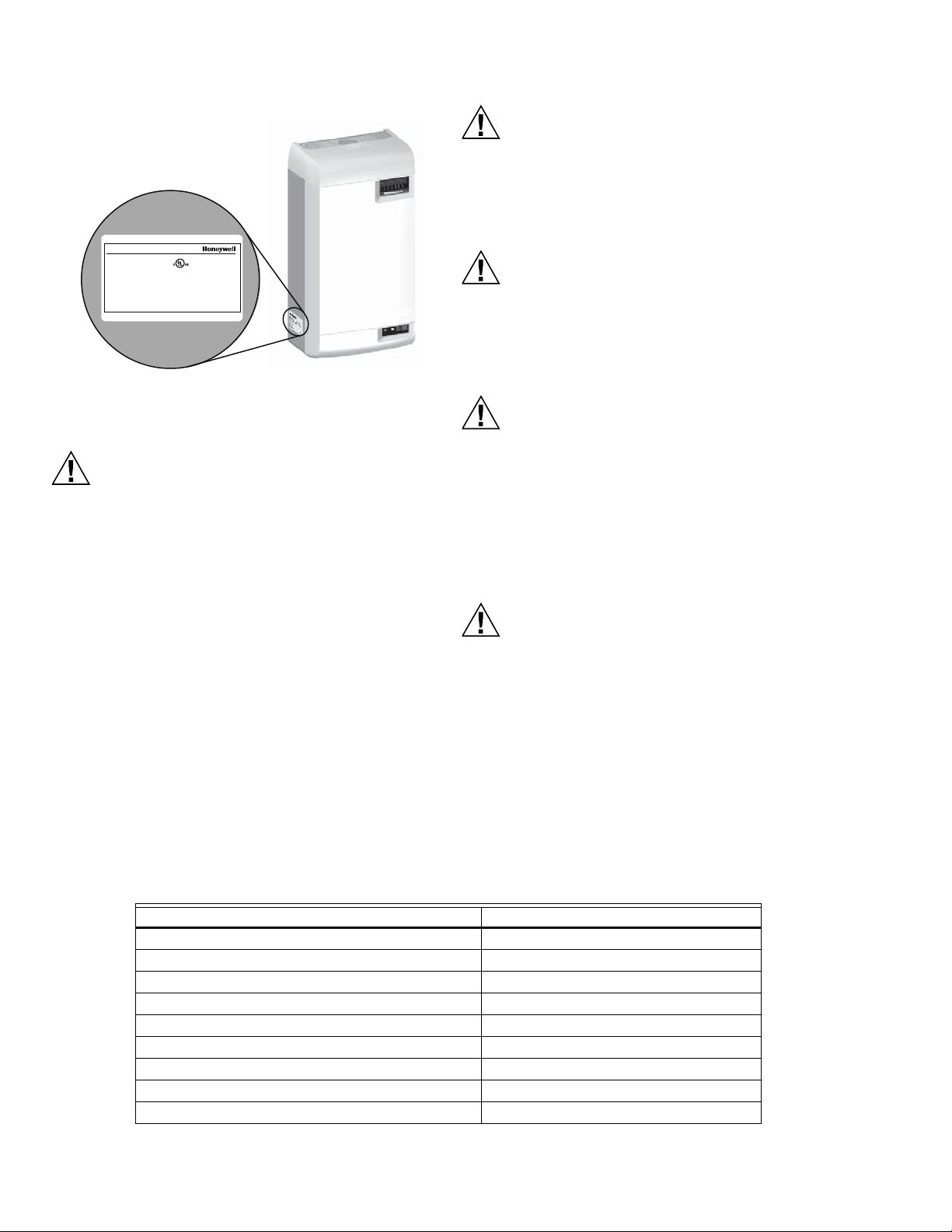
Servicing
Disconnect main power before any servicing.
The plumbing and electrical compartments contain
high voltage components and wiring. Access should
be limited to authorized personnel only.
During and following operation of the humidifier, the
steam and components in contact with the steam
such as the steam lines, steam distributors, and
condensate lines can become hot and can burn if
touched.
Honeywell does not accept any liability for installations
of humidity equipment installed by unqualified
personnel or the use of
parts/components/equipment that are not
authorized or approved by Honeywell.
To maintain warranty, only Honeywell approved parts
and cylinders may be used in the operation of the
product.
Electrical
All electrical work should be done according to local
and national electrical code.
Electrical connection to be performed by a licensed
electrician.
Unit must be powered by a dedicated GFI circuit.
Plumbing
Plumbing to be performed by a licensed plumber.
Drain water from humidifier can be very hot. Do not
drain to public sink.
All plumbing work should be done according to local
plumbing code.
Fig. 1. Specification label location.
Installation
Do not mount on hot surfaces.
Do not mount in area where freezing can occur.
Do not mount on vibrating surface.
Do not mount on floor.
The HM700 produces steam at atmospheric pressure.
No devices which could block steam output should
be connected to the steam outlet.
Steam lines must be installed so that no restriction can
produce backpressure in the humidifier.
Water quality
The Honeywell HM700 requires a cold water
connection from your home's main water supply
between 30-100 PSIG. A throttle valve may be
necessary, and a water shut-off valve is
recommended for safety. Reverse Osmosis (RO)
and Deionized (DI) water must not be used. Water
conductivity is important to ensure the electrode
humidifier operates effectively. Honeywell
recommends 150-1200 μS (microsiemens).
Parts and Accessories
The following parts and accessories are available and may have been included with your HM700 humidifier. The cylinder is the
only item that will need periodic replacement to maintain proper humidifier operation.
Table 2. Parts and accessories.
Part/Accessory Part Number
Replacement Cylinder HM700ACYL2
HumidiPRO Humidistat H6062A1000
Stainless Steel Distribution Remote Mount Kit HM700ADISTKIT
Replacement Drain Valve HM700ADVALVE
Replacement Fill Valve HM700AFVALVE
Replacement Transformer HM700ATX
Replacement PC Board HM700APCB
15 ft. Insulated Steam and Condensate Line Hose Kit HM700AHOSEKIT
33-00118EFS—01 2
Differential Pressure Switch for Air Proving 50027910-001
Page 3

How the Humidifier Works
The HM700 is an atmospheric steam generator that uses heat
generated by electrical current flowing between submerged
electrodes to generate steam. The HM700 is designed for ondemand air humidification via a steam distributor.
STEAM GENERATION
• Once the unit receives a demand signal and the safety loop
between terminal 1 and 2 is closed, the humidifier closes
the contactor and measures the electrical current.
• If the demand is lower than the actual output the inlet valve
is kept closed and output is reduced by letting the water
level in the cylinder decrease by evaporation.
• If demand is higher than the actual output, after a brief
delay the fill valve is activated and water flows into the fill
cup. Water from the fill cup flows into the bottom of the
cylinder through a hose connected to the drain valve
housing.
NOTE: The cylinder is gravity fed from the fill cup. If
backpressure from the steam line is too high it
will cause water to back up in the fill cup and
flow down the overflow line to the drain.
• As soon as the water in the cylinder comes in contact with
the energized electrodes, current flows through the water.
The resistance of the water to the electrical charge
generates heat and in turn steam. The electrical current
(and steam output) increases as the level of water
increases, as more of the electrode becomes submerged.
The unit continues to fill until the current matches demand
or the high water sensor detects a high water level.
• The HM700 repeats the fill and boil down cycle repeatedly
to match output to demand.
• Over time minerals in the water will adhere to the cylinder
electrodes. The humidifier will automatically fill to a higher
water level to maintain full capacity during the life of the
cylinder. Eventually because of scale formation it will no
longer be possible for the humidifier to reach its full
HM700A1000
capacity. The HM700 software monitors this condition and,
when detected, will stop operating and flash the yellow
LED in a repeating sequence of 4 flashes.
DRAINS
• As steam is produced, minerals are left behind, increasing
the conductivity of the water. The HM700 patented auto
adaptive cycle will monitor the water conductivity and
perform drains to maintain the water at optimal conductivity
for peak performance.
• The auto adaptive cycle ensures cylinder life is maximized.
It does this by keeping the tightest control and most
efficient use of water during the entire cylinder life.
STEAM DISTRIBUTION
Steam generated by the humidifier may be introduced into the
air in several different ways. The most common method for
adding the steam into the air is to mount a steam distributor
tube in a supply air duct.
STEAM LINE
The steam line between the cylinder steam outlet and the
distributor serves two purposes: it is used as a conduit to
transfer the atmospheric steam from the humidifier to the
distributor, as well as providing a means to remove
condensate. See “Steam Lines and Condensate Return
Instructions” on page 8 for information on selecting steam
lines.
CONDENSATE RETURN
Whenever steam is distributed condensate is formed in the
distribution system. Insulating steam lines is one important
way to reduce the amount of condensate formed. Steam lines
are sloped so that condensate does not collect in the lines and
create a restriction to steam flow. The condensate must be
collected and removed from the system so that it does not
build up and leak into the duct. Condensate can be returned to
the HM700 fill cup to reduce water waste or can be fed to
drain.
3 33-00118EFS—01
Page 4
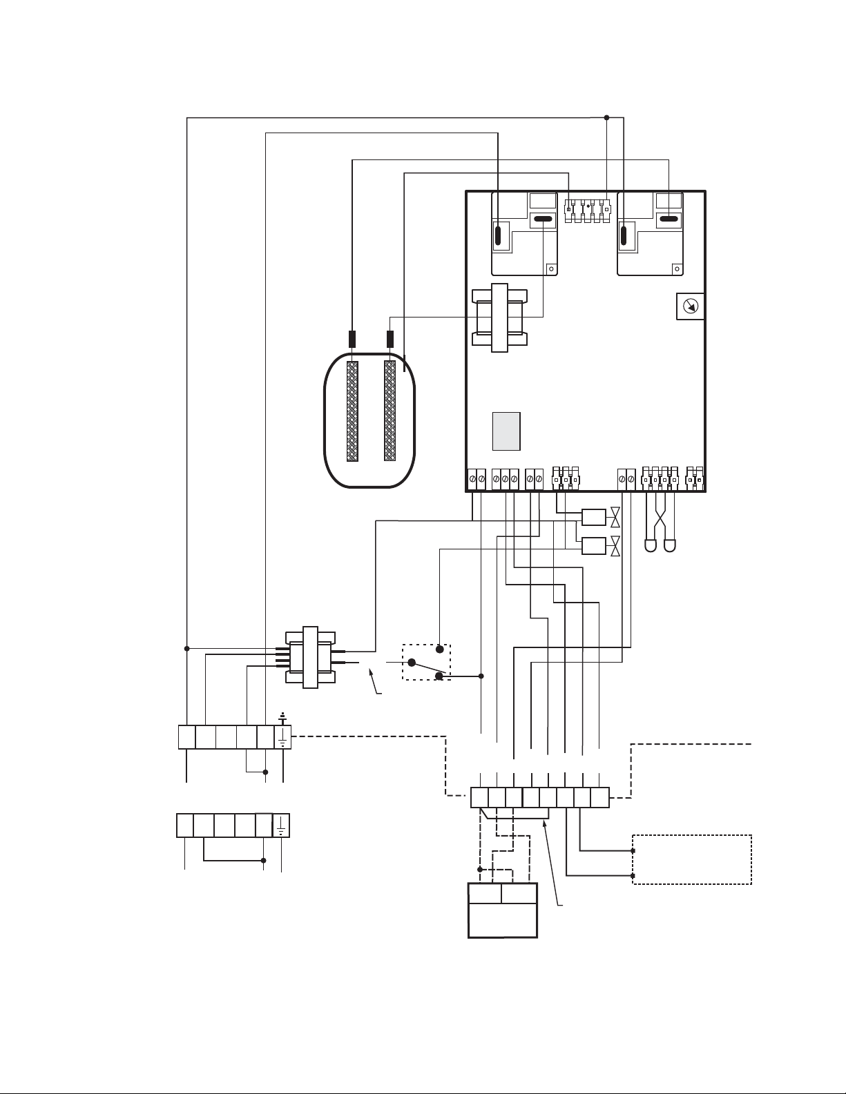
HM700A1000
(OPTIONAL)
1 - R/HUM
2 - HUM
3 - C
4 - N/A
8 - AP
19 - Gf
20 - Rf
21 - N/A
1/8 NPT TO 1/4
COMPRESSION
OR LDPE
WATER LINE
HM700
OFF
ON
DEDICATED
CIRCUIT
BREAKER OR
DISCONNECT
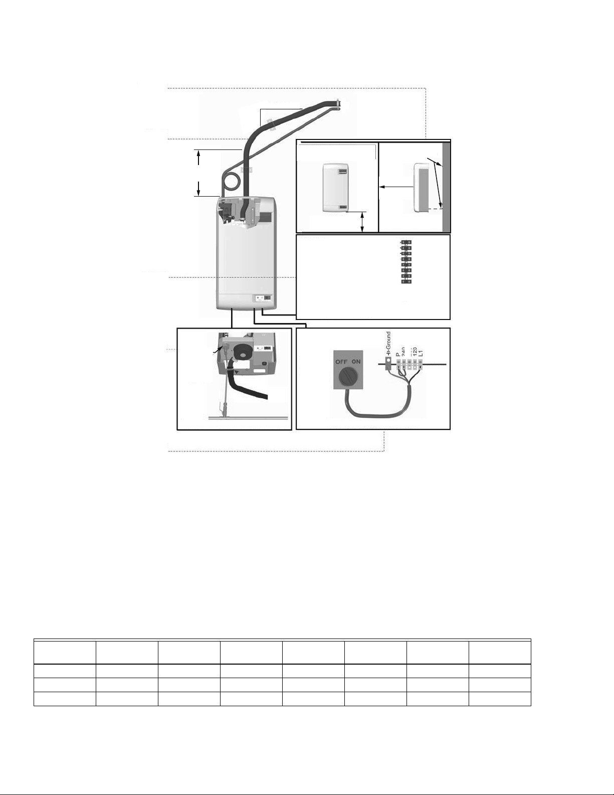
COLD POTABLE WATER, 30-100PSIG, 1/2 IN. MIN.
NOTE: 240 V CONNECTION SHOWN
EXTERNAL
M35805
24 (610)
MINIMUM HEIGHT
36 (914)
MINIMUM
2 (51) SCREWS
12 (305)
MINIMUM
MOUNTING
STEAM
DISTRIBUTION
CONTROLS
PLUMBING
ELECTRICAL
2 (51)
MINIMUM
12 (305)
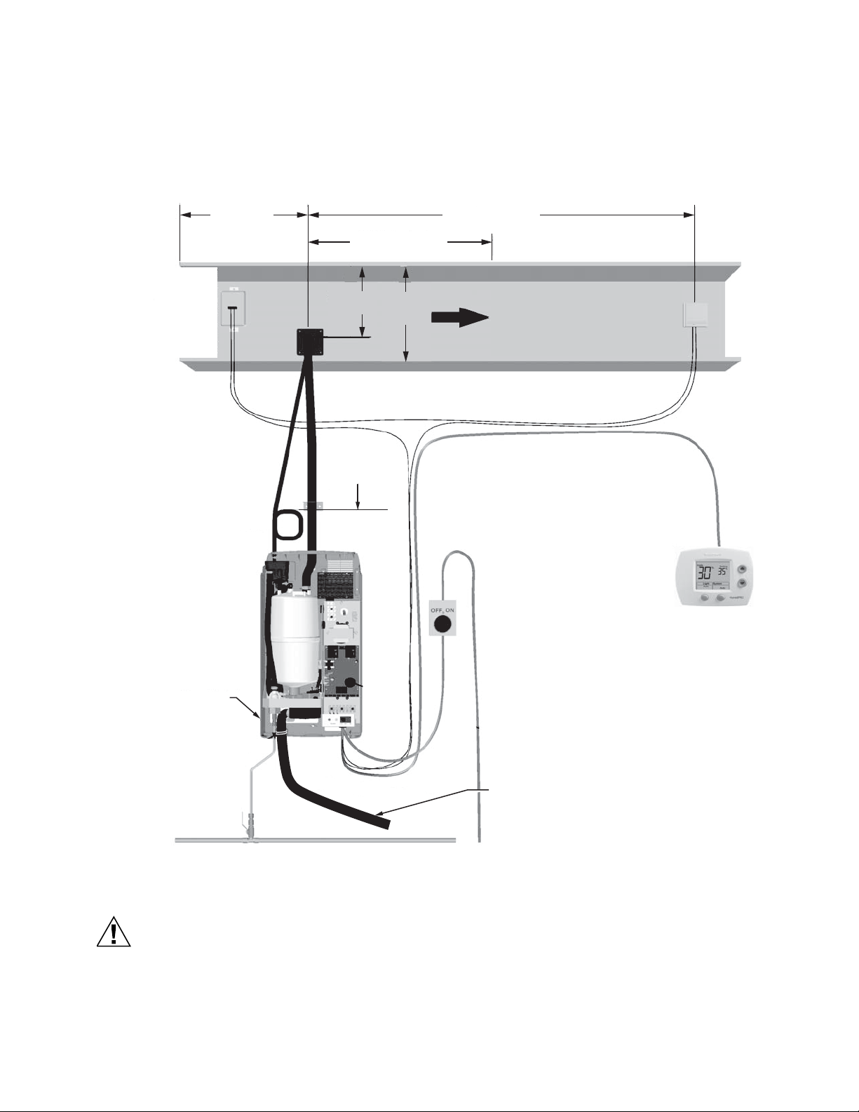
SIZING
IMPORTANT
The HM700 should only be installed if it has been
sized properly. Do not use square feet when sizing
a humidifier installation. Instead, cubic feet must
be used, since the humidity is filling a volume of
space (width x length x height). Also, take into
consideration the “tightness” of a home’s
construction.
Fig. 2. Typical HM700 Installation.
Measurements in inches (mm).
The HM700 produces 11 gallons per day (GPD) when run on
120 V and 22 GPD when run on 240 V. See Figure 16 for
details on configuring the HM700 to run on a different voltage.
Table 3 contains AHRI recommendations for humidity
requirements and Table 4 shows what humidifiers and output
configuration will satisfy the humidification requirements.
Table 3. AHRI Recommended Humidity (in gallons per day).
Construction
Type 8,000 ft
Tight 3.3 4.3 5.4 7.5 9.6 11.7 16
Average 7.6 9.6 11.8 16 20.3 24.4 33
Loose 11.7 14.9 18.1 24.5 30.8 37.1 50
3
12,000 ft
3
16,000 ft
3
20,000 ft
3
24,000 ft
3
28,000 ft
3
32,000 ft
3
33-00118EFS—01 4
Page 5
HM700A1000
INSTALL SECOND
SCREW AFTER
HANGING
HUMIDIFIER
#8 X 2 IN. (5 CM)
WOOD SCREWS
INSERT SCREW LEAVING
1/4 IN. (6 MM) EXPOSED.
HANG UNIT, THEN
TIGHTEN SCREW.
2X4 OR OTHER
STRUCTURAL
MEMBER
KEYHOLE
M35759
HOLE
Table 4. Steam humidifier(s) necessary for application.
Construction
Type 8,000 ft
3
12,000 ft
3
16,000 ft
3
20,000 ft
3
24,000 ft
Tight 11 GPD 11 GPD 11 GPD 11 GPD 11 GPD
Average 11 GPD 11 GPD 22 GPD 22 GPD 22 GPD
11 GPD (x3)
Loose 22 GPD 22 GPD 22 GPD
or
22 GPD (x2)
a
In the table above, 11 GPD indicates a steam humidifier configured to run on 120 V and 22 GPD indicates a steam humidifier
11 GPD (x3)
or
22 GPD (x2)
a
3
28,000 ft
11 GPD (x2)
22 GPD (x1)
11 GPD (x3)
22 GPD (x2)
11 GPD (x4)
22 GPD (x2)
3
32,000 ft
3
11 GPD (x2)
or
or
22 GPD (x1)
11 GPD (x3)
or
or
22 GPD (x2)
11 GPD (x5)
or
or
22 GPD (x3)
configured to run on 240 V.
LOCATION
NOTE: Do not mount on hot surfaces, where freezing
can occur, vibrating surface, or floor.
Mount on a suitable wall or vertical surface. Do not sit the unit
on the floor. Allow clearances required for plumbing and
electrical connections. Clearance dimensions shown are for
reference only and are the minimum required for maintenance
of the humidifier. Consult local and national codes before final
location and installation. Honeywell does not accept
responsibility for installation code violations.
• Install only in areas with ambient temperature 41 to 104 °F
(5 to 40 °C) and relative humidity 5 to 95 %.
• When possible install below the steam distributor. Take
care to provide proper steam line routing and proper
condensate traps.
• DO NOT locate the humidifier any further then absolutely
necessary from the steam distributor location as net output
will be reduced as a result of heat loss through the steam
line.
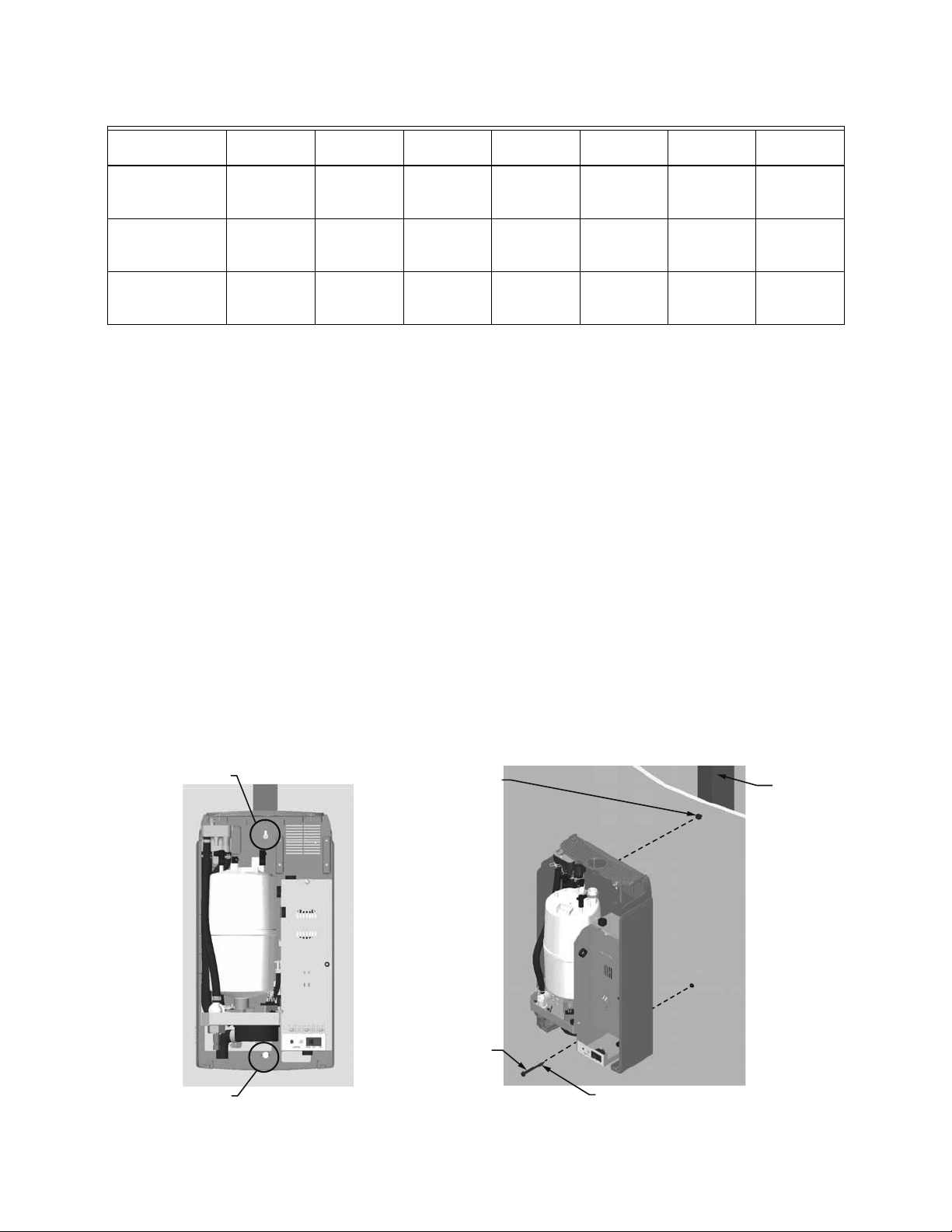
Mounting with Keyholes
1. The HM700 humidifier is wall mounted using a keyhole
located on the back of the unit cabinetry.
2. Use #8 x 2 in. (5 cm) screws mounted into 2x4 studs or
better. 2 screws are needed, one for hanging the unit
and one for securing so it will not lift off the keyhole.
3. Install the top screw so that 1/4 in. (6 mm) is exposed.
Raise the unit and place the screw head through the
keyhole.
4. Make sure the unit is level and then insert and tighten
the second screw through the bottom hole. Tighten the
top screw. See Fig. 3.
NOTE: Use screws longer than 2 in. (5 cm) if drywall or
other spacer is present.
• When possible, mount the HM700 humidifier at a height
convenient for servicing.
Fig. 3. Mounting with keyholes.
5 33-00118EFS—01
Page 6
HM700A1000
M35855
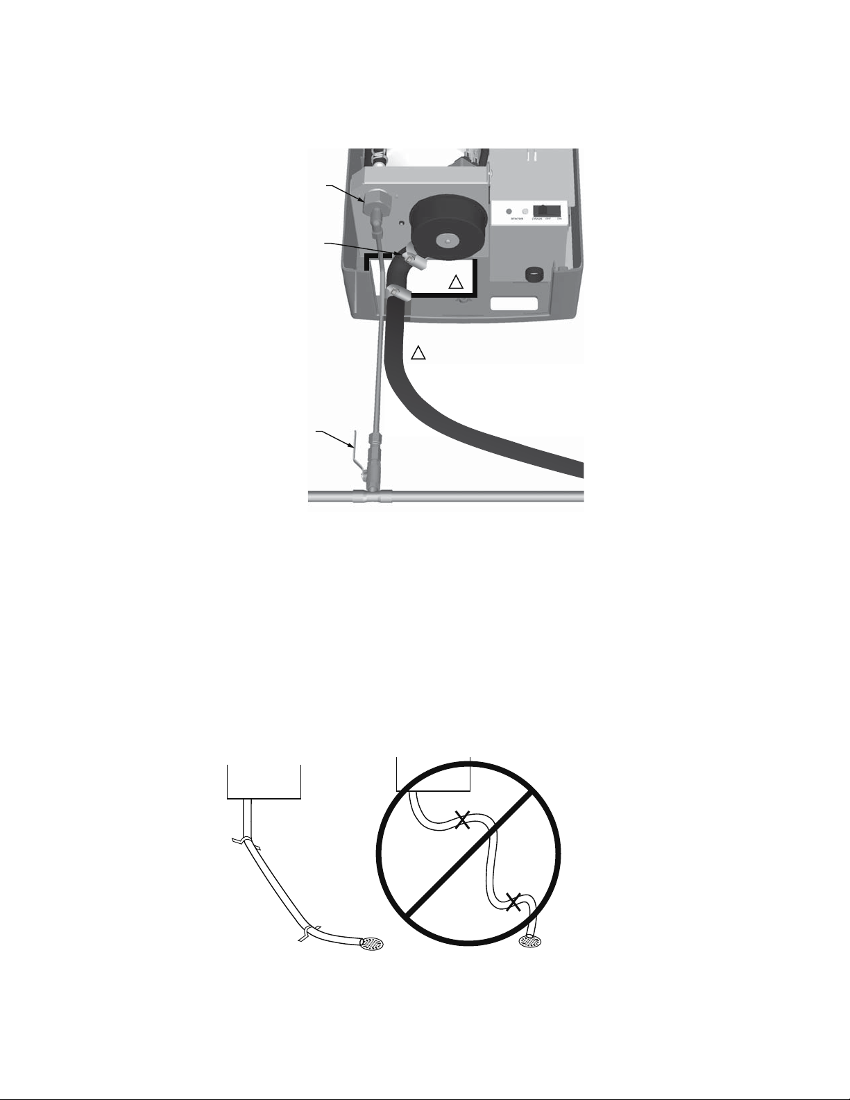
PLUMBING
USE 1/4 IN. COMPRESSION
FITTING (INCLUDED) TO
CONNECT WATER SUPPLY
LINE TO UNIT (LDPE PLASTIC
WATER SHUT-OFF VALVE.
OR COPPER).
1/2 IN. (30 MM) OD
ALWAYS INSTALL A
1
FILL AND DRAIN LINES CAN ALSO BE
1
ROUTED THROUGH OPENING IN BACK
OF CABINET.
Fig. 4. Water supply and drain connection.
IMPORTANT
— All water supply and drain line connections should be
installed in accordance with local plumbing codes.
— Drain water is automatically cooled to 140 °F (60 °C)
when HM700 cycles a drain. When the manual drain
switch is used, temperature may be higher. The drain
material (tube and drain) must be rated for 200 °F
(93 °C).
• Supply water should be between 30 to 100 PSIG. A throttle
valve may be used if necessary.
• Do not use reverse osmosis or de-ionized water. Supply
water should be between 150-1200 μS (microsiemens) for
optimal conductivity.
USE 1/2 IN. OD COPPER TO
WITHIN 4 FT (1.2 M) OF HUMIDIFIER.
M35760
• Supply water should be cold, 34 to 68 ºF (1 to 20 ºC).
• Install water shut off valve before humidifier to facilitate
servicing.
• The drain line should not end in a sink used frequently by
personnel, or where plumbing codes prohibit it. Route to a
floor drain or equivalent for safety reasons.
• Drain line should be routed to allow free flow of water.
Ensure adequate slope, no traps, and no kinks. A restricted
drain can cause cylinder water to over concentrate and
result in poor operation.
• If a drain is not located near the humidifier use a
condensate pump rated for hot drain water.
Fig. 5.
33-00118EFS—01 6
Page 7
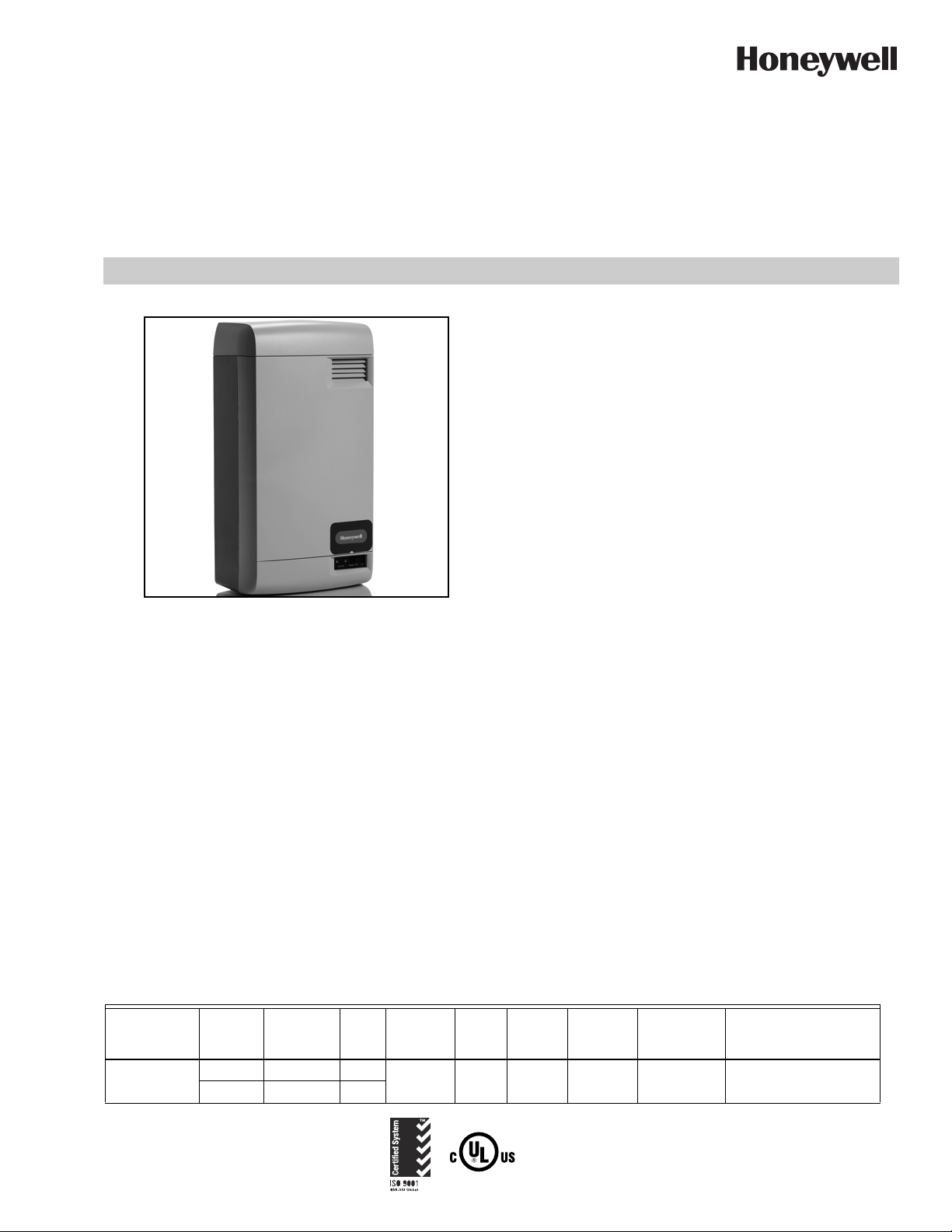
Steam Distributor
M35766
AIR FLOW
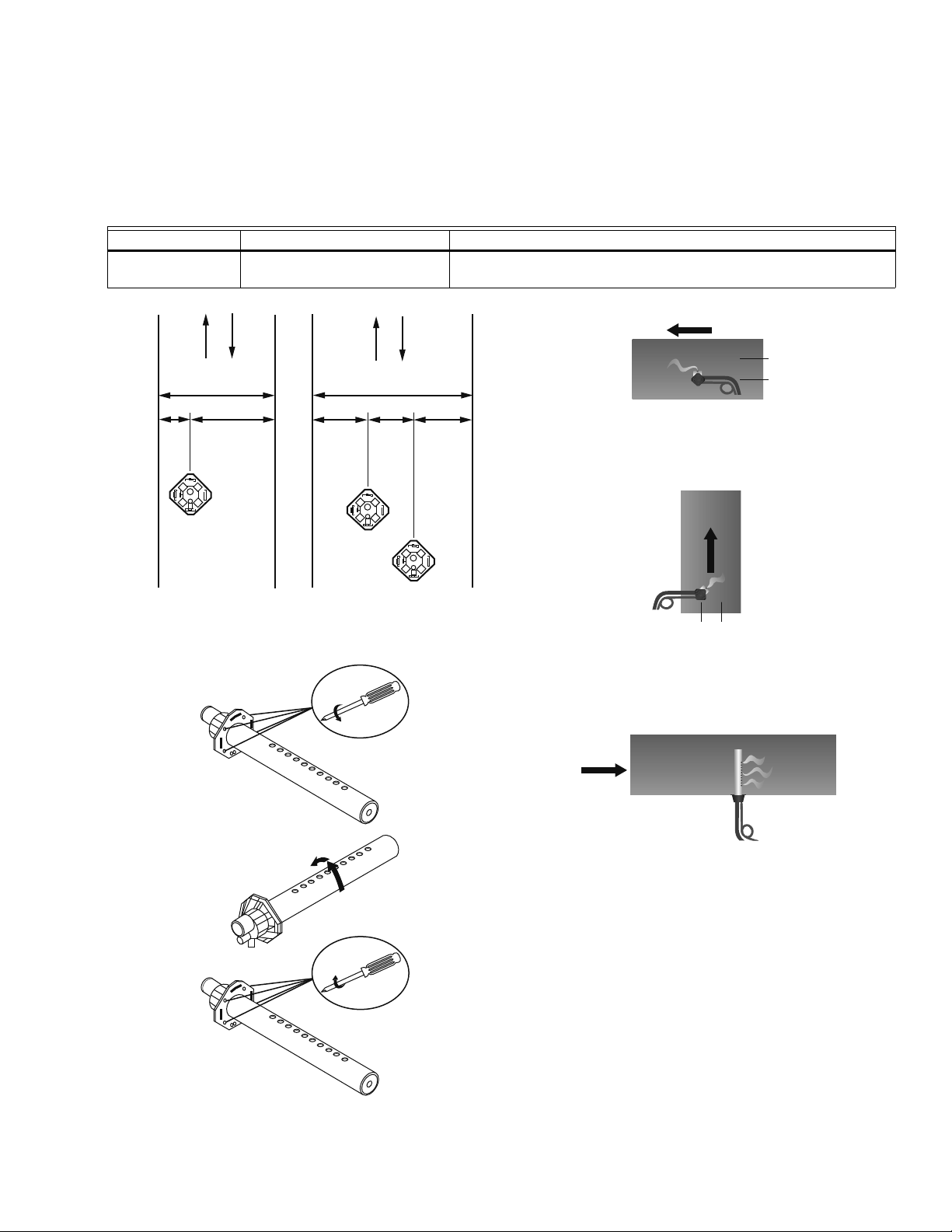
The HM700 requires a steam distributor installed in the
supply-side of ductwork. The HM700 can distribute steam into
a ventilation duct using the distributor shown in Table 5.
Table 5. Steam distributor.
Part Number Description Notes
HM700ADISTKIT
1/3W
Stainless Steel Distribution
Remote Mount Kit
W
2/3W
1/3W
H
1/3W
Includes a steam distributor, 5 ft. insulated steam hose, condensate
hose, and installation hardware.
1/3W
The steam distributor should be installed as close as possible
to the humidifier. Short steam distribution lines minimize
condensate loss and the possibility of generating
backpressure in the steam distribution line.
Fig. 8. Distributor installed horizontally
HM700A1000
AIR FLOW
2/3
1/3
M35764
in a horizontal duct.
MIN. W=8 (203)
1
2
3
Fig. 6.
+45˚
1 TURN
–45˚
M35755
AIR FLOW
1/3
2/3
M35765
Fig. 9. Distributor installed horizontally in a vertical duct.
Rotate the distributor 45º so that steam is discharged
toward the center of duct, in the direction of the air flow.
Fig. 10. Distributor installed vertically in a horizontal duct.
This configuration is not recommended.
M35756
Fig. 7.
7 33-00118EFS—01
Page 8
HM700A1000
M35761
SPRING CLAMP
3/8” OD COPPER TUBE
SPRING
CLAMP
INSERT HOSE OVER
COPPER TUBE AND
FASTEN WITH
SPRING CLAMP
Steam Lines and Condensate Return Instructions
The following instructions must be followed for installation of steam lines for the HM700. Failure to use recommended material
and exceeding maximum recommended length in Table 6, or failure to follow any other steam line installation instructions will
result in improper operation and could void the warranty.
Table 6. Recommended Steam Line Material for HM700 Duct.
Maximum
Steam Line
Length Possible Losses
Minimum
7 (2) 0.5 (0.2) 115
Airflow
CFM
Max
Static
Pressurelbs/hr (kg/hr)
3.0 in. w.c.
MED-L
Tube
*
Stainless
Steel
Tube ft (m) lbs/hr (kg/hr)
0.875 x
0.049W
Steam Output Material
Steam
Voltag e
110/120V 3.85 (1.75)
220/240V 7.7 (3.5) 12 (3.5) 1.5 (0.7) 230
Hose
7/8 in. 3/4 in.
Copper
* The use of steam line other than copper, stainless steel tube or Honeywell supplied steam line will void the warranty and may
adversely affect the operation of the humidifier.
* When using copper or stainless steel tubing (other than the supplied tubing), insulation is recommended due to high
temperature safety as well as reduced condensate.
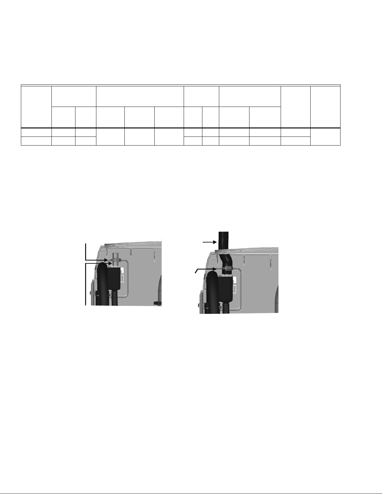
To return condensate for HM700, insert copper tube (supplied with equipment) half way into the condensate opening of the fill cup
along with the spring clamp (supplied with equipment).
Insert the condensate hose into the condensate return hole at the top of the HM700, and over the copper tube. Fasten in place
with the spring clamp.
Fig. 11. Condensate return.
MAIN RULES FOR ATMOSPHERIC STEAM LINES
• Steam lines must not have any restrictions which could result in back pressure.
• Follow recommended materials, size and length, see tables.
• Install steam line in a vertical (upwards) fashion from the HM700 to the distribution nozzle. Consult Figures 12-14 for other
installation options.
• Insulate with 1.0 in. (2.5 cm) pipe insulation.
• Trap condensate (Use full size ‘T’ for Traps)
• Do not over tighten hose clamp at cylinder steam outlet. The maximum torque is 12 in-lbs.
• Support steam line so weight is not on cylinder.
• Condensate traps must be a minimum of 6 in. (15 cm) in height or duct static pressure +2 in. (5 cm), whichever is greater.
• Trapping by P-trap or pigtail. Support line as necessary to ensure it remains free of kinks.
33-00118EFS—01 8
Page 9
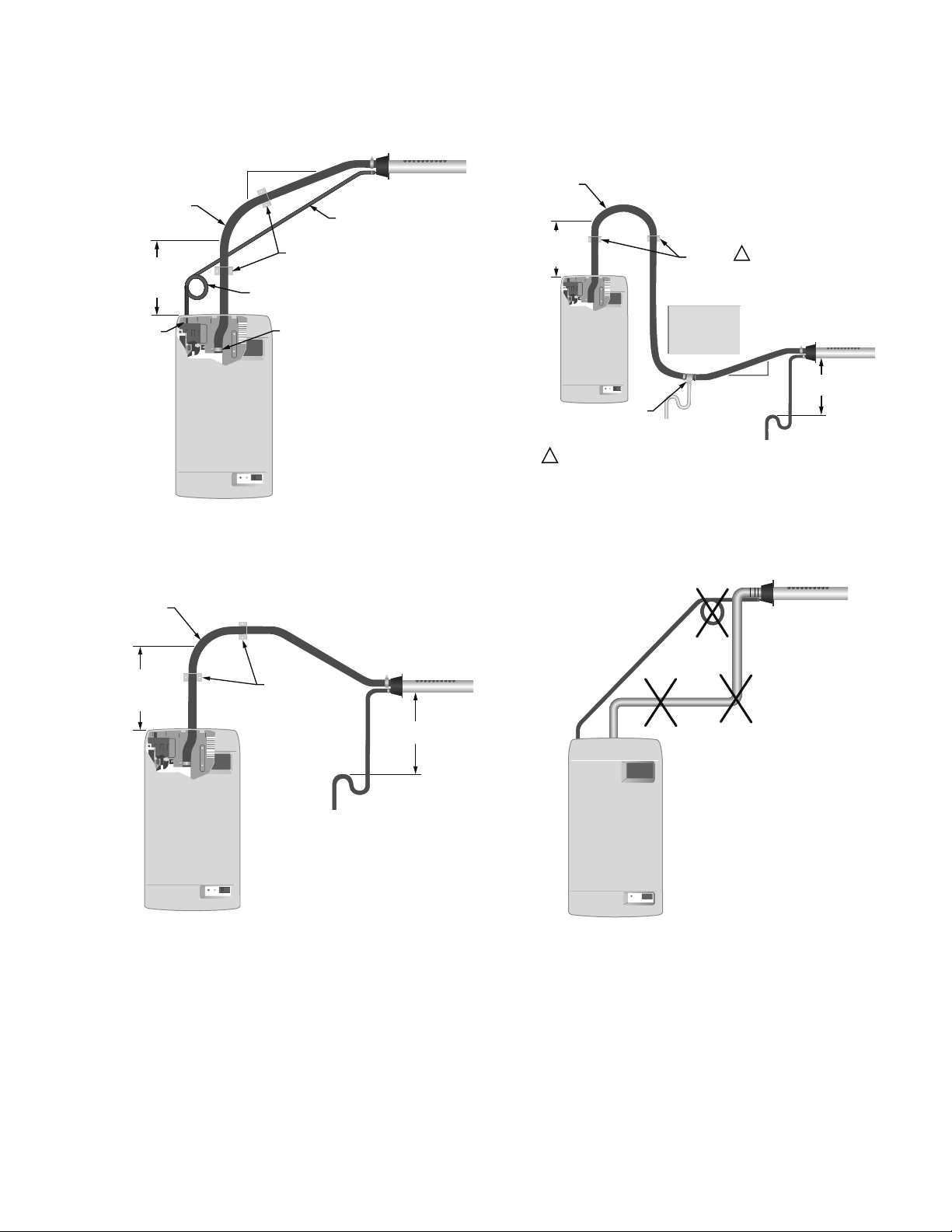
Steam Line Installation Examples
12 (305)
MINIMUM
M35718
SUPPORT
BRACKETS
CONDENSATE
TRAP
TO DRAIN
12 (305)
MINIMUM
RADIUS
12 (305)
MINIMUM
BEFORE
ANY BEND
A
M35720
NO
CONDENSATE
TRAP AT
VERTICAL
TRANSITION
STEAM LINE
NOT SLOPED
CONDENSATE
TRAP NOT 12
(305) BELOW
DISTRIBUTOR
HM700A1000
12 (305)
SUPPORT
BRACKETS
CONDENSATE
LINE
CONNECT
STEAM
HOSE TO
CYLINDER
CONDENSATE
LINE
M35717
12 (305)
MINIMUM
RADIUS
12 (305)
MINIMUM
BEFORE
ANY BEND
CONNECT
CONDENSATE
HOSE TO FILL
CUP
2 (51)
MINIMUM
Fig. 12. Steam distributor above humidifier (hose).
Measurements in inches (mm).
12 (305)
MINIMUM
RADIUS
12 (305)
MINIMUM
BEFORE
NY BEND
USE FULL SIZE CONDENSATE
TEE AT LOW POINT. SLOPE
LINES UP TO “T” AND
IMMEDIATELY AFTER IT.
HOSE WILL SOFTEN OVER TIME. PROPER SUPPORT IS NECESSARY.
1
OBSTRUCTION
TO DRAIN
SUPPORT
BRACKETS
1
2 (51)
MINIMUM
TO DRAIN
12
(305)
MIN.
12 (305)
MINIMUM
M35719
Fig. 14. Steam distributor below humidifier with
obstruction (hose). Measurements in inches (mm).
Fig. 13. Steam distributor below humidifier (hose).
Measurements in inches (mm).
Fig. 15. Common steam line installation errors.
Measurements in inches (mm).
9 33-00118EFS—01
Page 10
HM700A1000
CAUTION
CAUTION
WARNING
CAUTION
M35779
240 VAC
L1 N/A P120 240
120 VAC
Hot
Hot
Jumper
L1 N/A P120 240
Hot
Neutral
Ground Ground
Jumper
240 VAC
L1 N/A P120 240
120 VAC
Hot
Hot
Jumper
L1 N/A P120 240
Hot
Neutral
Ground
Ground
Jumper
M35850
ELECTRICAL
Wiring to be performed by a licensed electrician. This unit must be installed on a GFI Circuit.
Equipment Damage Hazard
Failure to wire the humidifier in accordance with the wiring instructions could cause permanent damage.
Such errors will void the warranty.
HM700A Humidifier must be installed using a dedicated 15 amp circuit breaker and hardwired directly to comply
with UL product listing. All wiring must be done per governing electrical codes.
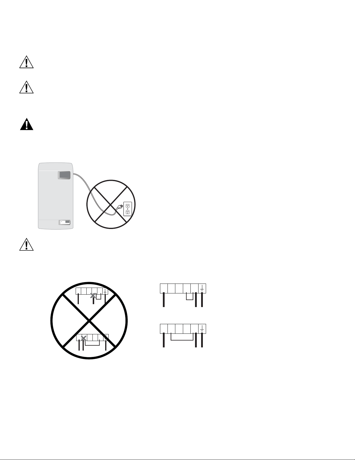
Electrical line cord plugs can overheat and result in risk of damage to property and/or personal injury. Note: Product
warranty will be voided if these instructions are not followed.
JUMPER WIRE INSTALLATION
• DO NOT install mains voltage wire (hot or neutral) into 120 or 240 terminal.
• DO install mains wires into L1 terminal (hot) and P terminal (hot/neutral).
• DO install jumper from P to 120 or 240 terminal (according to mains voltage).
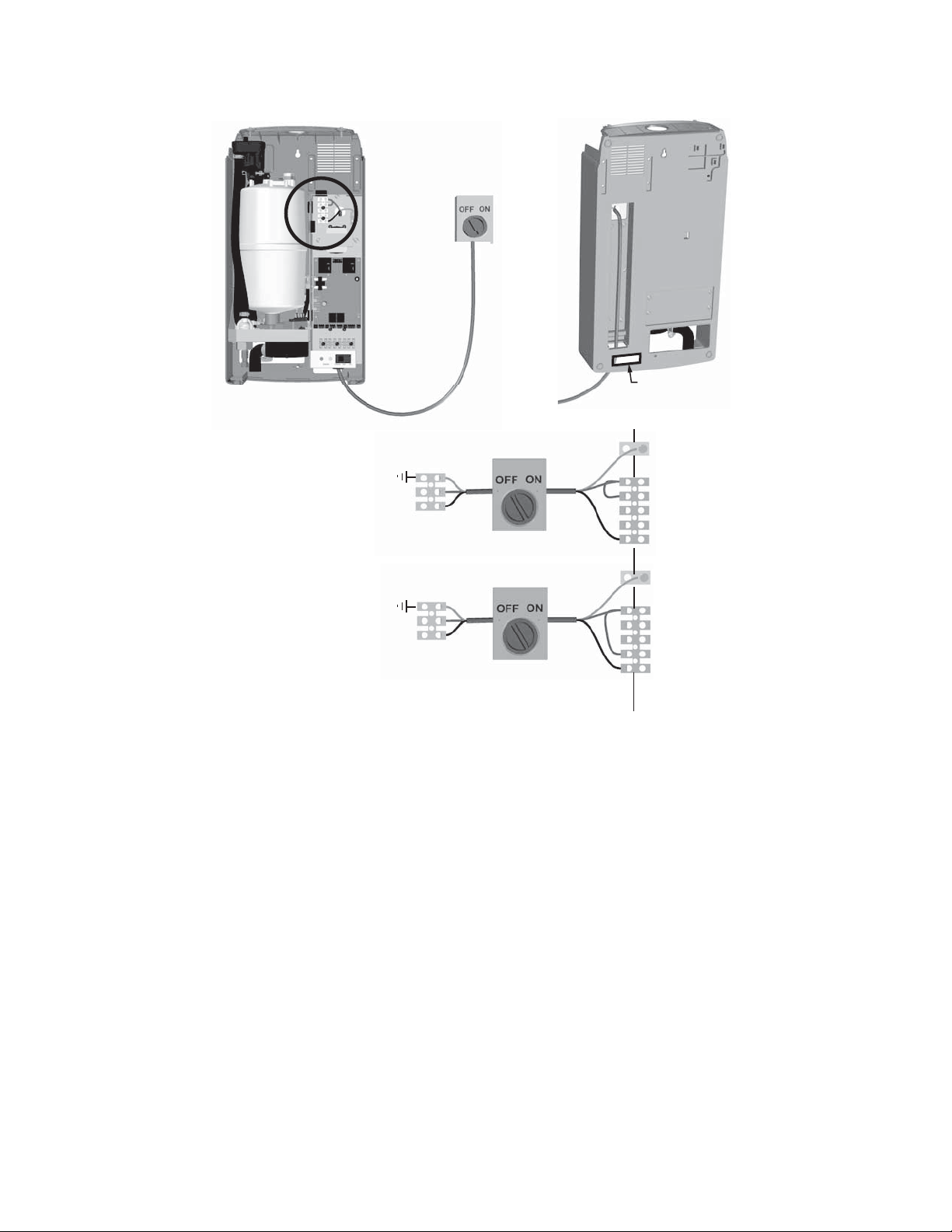
Installation Steps
1. Unit requires a dedicated circuit with GFI protection. Bring circuit to a disconnect near the device to protect from electrical
shock when servicing.
2. Hard wire humidifier to disconnect according as shown at right.
3. Install factory-supplied jumper between the P terminal and the terminal that corresponds to supply voltage.
4. Remove green wire attached to case body and drain valve (remove canister for access).
5. Clip ground wire as close to drain valve as possible and remove excess.
33-00118EFS—01 10
Page 11
HM700A1000
HOT
HOT
GROUND
P
240
120
L1
GROUND
E
X
T
I
N
T
240 VAC (1 PHASE)
120 VAC (1 PHASE)
NEUTRAL
HOT
GROUND
P
240
120
L1
GROUND
NOTE: CONNECT 120 VAC,
“HOT”, TO L1
(OPTIONAL)
(OPTIONAL)
NOTE: POWER WIRES
CAN ALSO BE ROUTED
THROUGH OPENING IN
BACK OF CABINET
M35806
Fig. 16. Primary power connection.
NOTES:
— Honeywell requires the use of a GFI circuit on this device to protect the homeowner from electrical shock.
— When installed correctly, the green wire should be removed from the drain valve. The green wire comes pre-installed
from the factory to protect the homeowner in case of an improper installation or when it is not possible to retrofit a GFI
circuit. See Fig. 24 for the location of green wire on the drain valve.
— Ensure that adequate power is available to carry full humidifier amp draw as indicated on the specification label.
— Do not use neutral wire as a ground; connect a dedicated ground to ground termination.
— All wiring to be in accordance with national and local electrical codes.
11 33-00118EFS—01
Page 12
HM700A1000
HVAC
THERMOSTAT
R
C
U
U
S
S
GYWRRc
GYWR C
R/HUM
HUM
C
N/A
AP
G
F
R
F
N/A
M35754
OUTDOOR
SENSOR
AIR PROVING
OR JUMPER
EXTERNAL CONTROLS
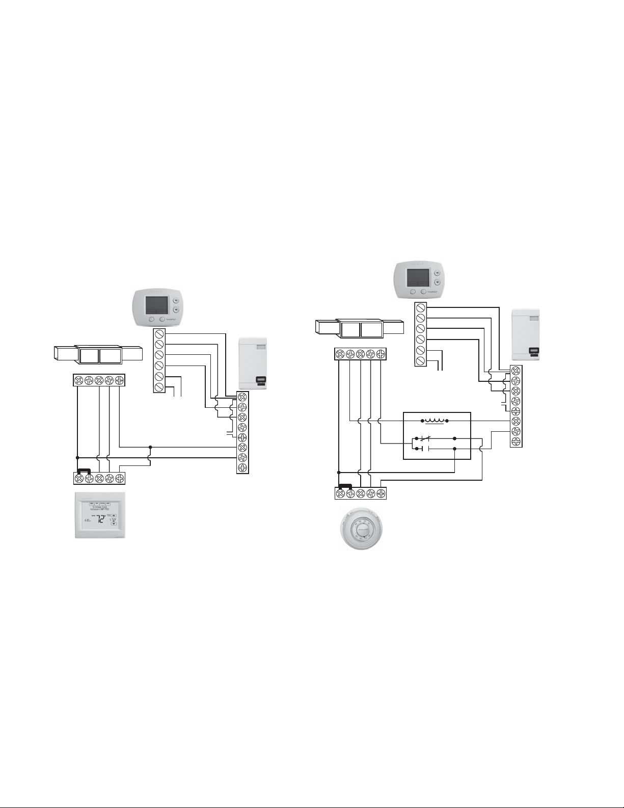
Fan Interlock Wiring with HumidiPRO
When distributing steam into a duct, there could be a call for
humidity when there is no air flow. The HM700 with
HumidiPRO control or some other thermostat (such as the
Honeywell Prestige of VisionPRO
fan on a call for humidity. If using another thermostat, consult
that control’s manual for wiring instructions to enable the fan
with a powered humidification device.
NOTE: Humidifier will not start producing steam until
fan security loop is closed.
®
) can be used to enable a
This information is relevant to all controls, factory supplied or
otherwise. For wiring use minimum 18 AWG solid wire and
keep as short as possible.
Humidity Control
• Can be located either in return air duct (preferred) or in
room being humidified.
• Avoid placing near discharge diffuser of humidified air.
• Mount in area representative of room humidity (drafts,
doorways, sunlight, or an overhang such as a shelf can
affect reading).
Optional Outdoor Temperature Sensor (not shown; included
with HumidPRO)
• Mount outside in area representing air temperature.
HVAC
R
C
U
U
GYWR C
S
S
SPDT RELAY
COM
OUTDOOR
SENSOR
NC
NO
AIR PROVING
OR JUMPER
R/HUM
HUM
C
N/A
AP
G
F
R
F
N/A
NOTE:
SPDT RELAY IS NECESSARY TO PREVENT
ENERGIZING THE Y TERMINAL IF THE
GYWRRc
THERMOSTAT DOES NOT ISOLATE Y AND G.
Fig. 17. Wiring the steam humidifier with a digital thermostat.
THERMOSTAT
Fig. 18. Wiring the steam humidifier with a mechanical
M35730
thermostat.
NOTE: If a Prestige, VisionPRO, Lyric (or similar) are used to control humidity, wire the two HUM contacts to terminals 1 and 2
33-00118EFS—01 12
on the HM700. With the jumper in place between terminals 1 and 8 on the HM700, only these two wires are necessary
to control humidity. Be sure to configure the control to force fan on with a call for humidity, or run on a heat cycle if the fan
enable wiring is not used.
Page 13
START UP
CAUTION
FUSED DISCONNECT
CORRECT VOLTAGE / AMPS /
PHASE PER SPEC LABEL
(OPTIONAL)
MOUNTING
- UNIT LEVEL
- SCREWS INTO
STRUCTURAL
MEMBER
STEAM LINE
- ADEQUATE SLOPE
- NO RESTRICTIONS
- NO KINKS IN HOSE
- CONDENSATE TRAPS
ON LONG RUNS
HUMIDITY CONTROL
IN RETURN DUCT OR
LOCATION WHICH
REPRESENTS HUMIDIFIED
SPACE (NO DRAFTS, NOT
BY DOOR, NOT BY DIFFUSER)
1/2 IN. LINE (MINIMUM) TO WITHIN 4 FT (1.2 M). 30-100 PSIG
SPEC LABEL
AIR GAP
P TRAP
WITH 12 IN (30 CM)
MINIMUM DROP
BEND, OR OTHER
OBSTRUCTION
NOTE: U OR HUM TERMINALS IN SERIES BETWEEN TERMINALS 1 AND 2
AIR PROVING
(OPTIONAL)
IN SERIES BETWEEN
TERMINALS 1 AND 2.
JUMPER BETWEEN
TERMINALS 1 AND 8
MUST BE REMOVED.
2X DUCT HEIGHT
FROM FAN OR
TRANSITION
10 FEET (3 M) MINIMUM
4 FEET (1219) MINIMUM
2/3 DUCT
HEIGHT
8
(20 CM)
MINIMUM
HIGH LIMIT
ON/OFF
(OPTIONAL)
IN SERIES BETWEEN
TERMINALS 1 AND 2.
JUMPER BETWEEN TERMINALS
1 AND 8 MUST BE REMOVED.
M35807
DRAIN LINE SHOULD BE ROUTED TO ALLOW FREE FLOW OF
WATER. ENSURE ADEQUATE SLOPE, NO TRAPS, AND NO KINKS.
Installation Check
Before turning on power to the HM700, inspect the installation to ensure that it was carried out correctly.
HM700A1000
Fig. 19. Installation check.
Equipment Damage Hazard
Do not leave the On/Off/Drain switch in the drain
position for more than one complete drain cycle. The
drain valve solenoid may heat up and result in damage
to the valve and its wiring.
Do not attempt to drain with no water in system.
On/Off
The HM700 is factory-configured to operate as an On/Off
humidifier. It will run when 24 VAC from terminal 1 is fed back
into terminal 2 through an On/Off humidistat and other
security devices in series.
13 33-00118EFS—01
Page 14

HM700A1000
WARNING
Start Up Procedure
1. Examine the humidifier and installation for damage
and/or improper installation.
2. Ensure the cylinder is properly seated in the drain valve
and that the electrode plugs are pushed all the way
down on the cylinder pins.
3. Ensure that the front cover is in place and secured with
its retaining screws.
4. Open the supply water shut off valve.
5. Turn on the main power using the installed disconnect.
Personal Injury Hazard.
Damaged or improperly installed units must not be
operated. Damaged or improperly installed units may
present a danger to persons and property.
6. Turn the On/Off switch on the front of the humidifier to
On.
• The humidifier will perform a self-diagnostic
sequence during which the LED’s and internal
components will be momentarily activated. See
“LED Status Lights” on page 15 for an explanation
of the LEDs and sequences.
• If an error is detected during the self-diagnostic
sequence the humidifier will not start. The yellow
status LED will flash in sequence to indicate the
detected fault. See Tables 7 and 8 for information
on diagnosing and correcting faults.
• After the system test the humidifier is in normal
operation mode.
7. Check and adjust the control setpoint on the control and
high limit humidistat.
8. When the external humidistat generates a demand for
humidity and the security loop is closed the green
humidifying LED on the front of the humidifier will light
up, the power relay on the control board will engage, the
fill valve will activate (after a delay) and the cylinder will
slowly fill with water.
NOTE: While the cylinder is filling with water there
should be no water flowing down the drain. If
water is flowing down the drain it can indicate
excessive backpressure or a leaking drain valve.
See Troubleshooting.
9. If a fan enable relay is used, the green LED will continue
to flash until the air proving closes. Once the air closes,
the flashing green LED will become solid and the
humidifier will start steam production as described in
step 8.
10. It can take 5 – 10 minutes for the water to be heated up
by the submerged electrodes and for steam to be produced.
NOTE: If operated on low conductivity water it may take
several hours for the HM700 to reach full output
capacity. This is normal. During this time the
humidifier will not perform any drains and the
conductivity of the water in the cylinder will
increase. To expedite this process, add a
1/4 teaspoon of salt to the cylinder. This will
immediately increase water conductivity and
initiate heating.
33-00118EFS—01 14
Page 15
OPERATION
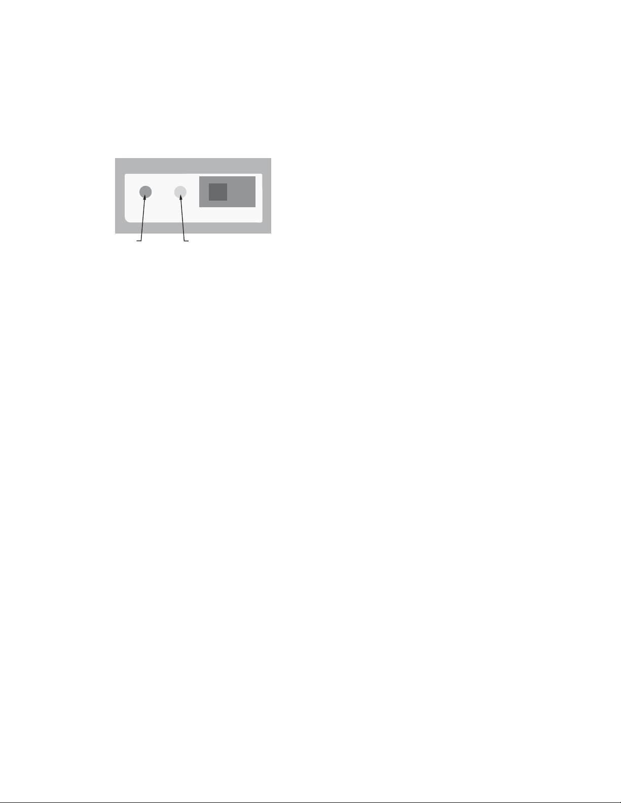
M35828
STATUS
DRAIN OFF ON
YELLOWGREEN
HM700A1000
LED Status Lights
The HM700 user interface includes 2 LEDs that provide
information about the humidifier status.
Fig. 20. LED status indicator lights.
Yellow and Green LED Flashing
Indicates there is no request for humidity.
Yellow LED Flashing
Fault detected, humidifier has stopped operating. Count
the number of flashes and see Table 8 for info.
Green LED Flashing
Indicates the humidifier is powered, but there is not a
request for humidity. Security loop (1-2) is open.
Yellow LED On
Indicates that water level is high.
When the yellow LED is steady on (not flashing) it indicates that the high water sensor has interrupted filling of
the cylinder. The LED is on for information only and
unless it persists for an extended period of time, it does
not require any action.
Green LED On
Indicates steam is being produced.
Selecting a Relative Humidity Setpoint
The optimum humidity setpoint depends on the reasons that a
space is being humidified. The “ASHRAE Handbook HVAC
Applications” recommends specific design relative humidity for
specific applications.
Health and Comfort – The benefit of humidity is most
pronounced for health and comfort in the 40-60% range. A
humidity setting of 45-50% is recommended for this purpose
to prevent over humidifying.
Temperature Setback – In cold climates it is often necessary
to reduce the humidity level in a conditioned environment to
prevent build-up of condensation on the inside of exterior
walls, windows, and trim. It is highly recommended that the
humidity setback function of the HumidiPRO control be used
under these conditions to prevent damage from condensation.
The digital control with an outdoor temperature sensor
installed will automatically setback the humidity setpoint to
correspond with outdoor temperature.
15 33-00118EFS—01
Page 16
HM700A1000
STEAM
OUTLET
CONDENSATE
RETURN
FILL CUP
DRAIN VALVEDRAIN CANAL
FILL VALVE
CYLINDER
CYLINDER
PLUG
HIGH WATER
SENSOR PLUG
ON/OFF/DRAIN
SWITCH
CONTROL
BOARD
POWER RELAY
HIGH VOLTAGE
TE RM IN A L
BLOCK
TRANSFORME R
CONTROL
TE RM IN A L
STRIP
M35827
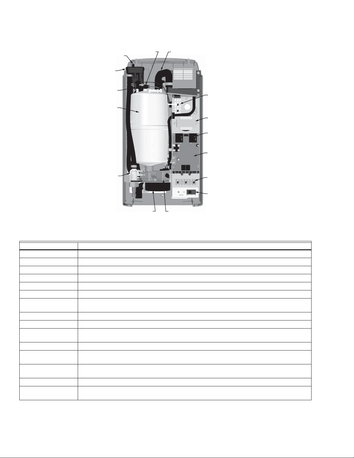
Fig. 21. Humidifier components.
Component Function
Condensate Return Provides a connection to return condensate to humidifier.
Control Terminal Strip Terminal strip for connecting external controls to humidifier and interfacing with other equipment.
Cylinder Plug Power connectors to electrodes in cylinder.
Cylinder Holds electrodes in water. Current between electrodes generates heat used to generate steam.
Drain Canal Combines cylinder drain water and fill cup overflow into a single drain outlet.
Drain Valve Drains water from humidifier.
Control Board Controls all functions of the humidifier operation and provides input and output connections to
humidifier components.
Fill Cup Provides an air gap for backflow prevention.
Fill Valve Controls flow of water into humidifier.
High Voltage Terminal
Block
High Water sensor Plug Used to detect max water level in cylinder.
Primary power connection from remote disconnect to humidifier.
On/Off/Drain Switch Turns power on/off to humidifier controller and drains the cylinder for servicing. Note: Turn off
humidifier disconnect to shut off primary power to the humidifier.
Power Relay Turns on/off power to cylinder electrodes based on a signal from the humidifier’s controller (mounted
on control board).
Steam Outlet Connect to steam line with steam hose.
Transformer Steps primary voltage down to 24 VAC for the controller and internal components such as the fill valve
and drain valve.
33-00118EFS—01 16
Page 17
MAINTENANCE AND SERVICING
CAUTION
M35704
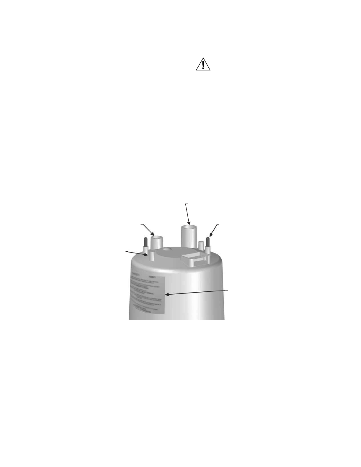
ELECTRODE INTERNAL
MOUNTING POINT.
HIGH WATER SENSOR PIN HAS
A PLASTIC COLLAR AROUND IT.
CONNECT ORANGE HIGH WATER
SENSOR WIRE HERE.
STEAM OUTLET
SECURE STEAM HOSE TO
OUTLET WITH HOSE CLAMP.
ELECTRODE PIN
CONNECT COLOR CODED CYLINDER
PLUGS TO PIN WITH CORRESPONDING
COLOR LABEL. THE SPRING LOADED
PLUG SHOULD FIT SNUGLY ON THE PIN.
REPLACE IF LOOSE OR ANY SIGNS OF
DAMAGE.
LABEL
IDENTIFIES CYLINDER INFORMATION.
ALSO INCLUDES SAFETY INFORMATION
AND CONTACTS.
Required Maintenance
The HM700 humidifier has been designed to require very little
maintenance. Regular maintenance consists of checking the
humidifier to ensure it is in good condition, replacing the
cylinder when the software advises that the cylinder is spent
and cleaning out the drain valve whenever the cylinder is
replaced.
CYLINDER SPENT FAULT
When the cylinder is spent the HM700 will stop operating and
the yellow LED will flash in a repeating pattern of 4 flashes.
See Table 8 on page 22 for more information on other flash
sequences. At this time the cylinder must be replaced.
The steam cylinder is disposable and must be replaced at end
of cylinder life. Cylinder life is dependent on water supply
conditions and humidifier usage.
HM700A1000
Failure to replace the cylinder at the end of
cylinder life will result in improper operation and
may result in damage to the humidifier. Honeywell
is not responsible for any damages resulting from,
or attributed to, the failure to replace a spent
cylinder (see Manufacturer’s Warranty).
NOTE: Honeywell recommends keeping a replacement
cylinder in stock throughout the humidification
season. This will prevent possible downtime
when the humidifier reports cylinder end of life.
REPLACEMENT CYLINDER
The label on the existing cylinder identifies the cylinder type in
its top left corner. When ordering a cylinder always quote the
three or five digit model number on the label, the humidifier’s
serial number and the humidifiers voltage. Serial number and
voltage are located on the specification label on the left side of
the humidifier.
Fig. 22. HM700 cylinder (HM700ACYL2).
17 33-00118EFS—01
Page 18
HM700A1000
WARNING
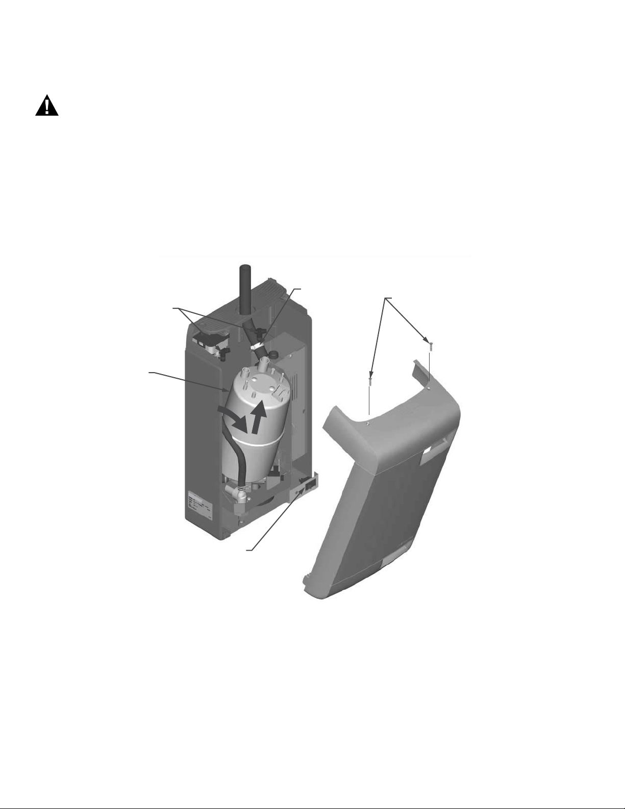
HOSE CLAMP
CYLINDER PLUG
LIFT VERTICALLY
ON/OFF/DRAIN SWITCH
CYLINDER
COVER SCREWS
TILT CYLINDER
FORWARD TO CLEAR
HOSE AND THEN
LIFT FROM DRAIN
VALVE.
TILT COVER
FORWARD TO
REMOVE.
M35705
Removing the Cylinder
Disconnect main power at the external disconnect
before any servicing.
The inside of the humidifier cabinet contains high
voltage components and wiring. Access should be
limited to authorized personnel.
1. Drain the existing cylinder by switching the On/Off/Drain
switch to the Drain position. Let the humidifier drain until
no more water is flowing out to drain (usually not more
than 10 minutes).
2. Turn the humidifier On/Off/Drain switch to off.
3. Close supply water shut off valve.
4. Turn off power to the humidifier with the external discon-
nect.
5. Remove the two screws securing the front cover.
6. Remove the cylinder plugs from the cylinder pins by
pulling vertically.
7. Using a flat screwdriver loosen the hose clamp where
the hose is connected to the cylinder.
8. Tip the top of the cylinder forward to pivot it out of the
steam hose. When free of steam hose lift the cylinder
out.
NOTE: The HM700 has a re-usable tie strap to secure the
cylinder for transit as well as home installation.
This must be removed or loosened to remove the
cylinder. Secure when new cylinder is installed.
33-00118EFS—01 18
Fig. 23. Cylinder removal.
Page 19
HM700A1000
CAUTION
CYLINDER PORT
AND O-RING
GROUND
WIRE
SOLENOID
SPADE
CONNECTORS
BRASS NUT
(ACTUATOR)
SCREWS
HOSE AND
HOSE CLAMP
M35700
M35707
SLEEVE AND
SOLENOID
SPRING
(NOTE ORIENTATION)
PLUNGER
ACTUATOR
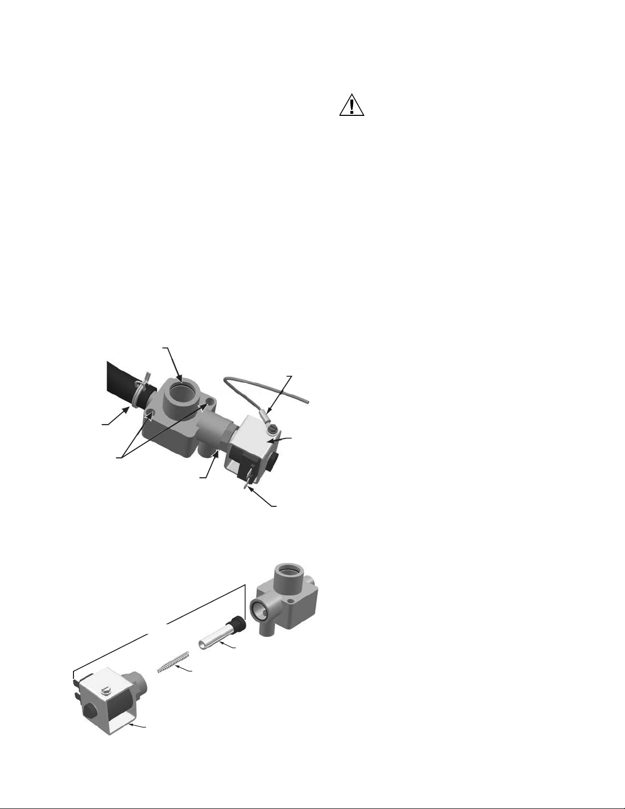
Drain Valve Cleaning
Always clean the drain valve before installing a new cylinder.
Scale from the spent cylinder may have fallen into the drain
valve and could prevent its proper operation. To properly clean
the drain valve it must be removed and disassembled.
1. Disconnect spade terminals from the drain valve.
2. Remove the two screws holding the valve to the drain
pan.
3. Squeeze the tabs of the spring clamp holding the hose
to the drain valve and slide it up the hose. Pull hose
from drain valve. Lift the drain valve from the drain pan.
4. Unsnap red coil cap on solenoid and remove the sole-
noid from the valve.
5. Loosen brass nut holding actuator to plastic housing
with a wrench and disassemble actuator.
6. Clean actuator components and valve housing (inlet
port, outlet port, and cylinder port). Put new o-ring that
was supplied with new cylinder into valve.
7. Reassemble actuator making sure tapered end of
spring is oriented as shown in Fig. 25. Tighten brass nut
1/4 turn past hand tight.
8. Clean out end of hose and reattach to valve. Slide hose
clamp back in place and place valve into drain pan.
9. Secure valve with 2 screws to drain pan.
Installing the New Cylinder
Make sure the new cylinder is a HM700ACYL2. Use
of any other model or remanufactured cylinders
will void the HM700 warranty.
1. Insert cylinder into drain valve. Tilt cylinder forward and
fit end of steam hose to steam outlet. Tip cylinder back
into place.
2. Tighten hose clamp being careful not to over tighten and
crush the plastic cylinder steam outlet.
3. Attach color-coded cylinder plugs to the corresponding
color-coded cylinder pin. Push down completely.
Connect high water sensor plug. Spring-loaded plugs
should fit snuggly onto the cylinder pin. Replace if they
are loose or damaged.
4. Re-fasten tie strap.
5. Replace the humidifier cover and secure with two
screws.
6. Turn on power to humidifier with the external
disconnect.
7. Open supply water shut off valve.
8. Turn the humidifier On/Off /Drain switch to On.
Extended Shutdown
Should it be required to disconnect power to the humidifier for
a period of extended shut-down, always drain the cylinder first.
Fig. 24. Drain valve.
1. Switch the On/Off/Drain Switch to the Drain position.
2. Wait until the humidifier is completely drained (usually
takes less than 10 minutes).
3. Turn the On/Off /Drain switch to the off position.
4. Shut off power to the humidifier with the external
disconnect.
5. Close the supply water shut-off valve.
NOTE: As long as the HM700 is powered, it will
automatically drain the cylinder when there has
not been a call for humidity for an extended
period of time. This feature will reduce or prevent
the possibility of corrosion of the electrodes and
the accumulation of algae and bacteria growing
in the cylinder. The cylinder will remain empty
until there is a call for humidity at which time the
fill valve will open and refill the cylinder. The unit
will go through its normal process for optimum
operation.
STARTING AFTER EXTENDED SHUTDOWN
1. Check to see the humidifier has not been damaged and
the installation has not been altered. See “Start Up
Procedure” on page 14.
2. Turn on the power to the humidifier with the external
disconnect.
3. Turn the On/Off/ Drain switch to the Drain position.
4. Wait until there is no water flowing to drain. It usually
takes less than 10 minutes.
5. Follow the start up procedure on page 14.
Fig. 25. Drain valve actuator assembly.
19 33-00118EFS—01
Page 20
HM700A1000
CAUTION
CAUTION
TROUBLESHOOTING
High Voltage Hazard.
Be aware, when troubleshooting, that the humidifier is
powered by high voltage and familiarity with both good
practices and wiring of the humidifier is recommended.
Any troubleshooting that requires opening the cabinet
should be done by qualified personnel.
Burn and Scalding Hazard.
Hot water or steam with a temperature above 120 °F
(49 °C) can cause burns from scalding.
NOTE: Most humidifier faults are not caused by faulty
equipment but rather by improper installation. A
complete fault diagnosis always involves a
thorough examination of the entire system.
Often, the steam hose connection has not been
properly executed, or the fault lies with the
humidity control system.
TROUBLESHOOTING REQUIREMENTS
• Ensure the installation meets the installation requirements
outlined in the Installation Chapter of this manual.
• Familiarize yourself with the operation of the humidifier by
reading the Operation Chapter of this manual.
• Wiring diagram for specific for your humidifier is installed
on the inside of the humidifier door. A generic copy of the
HM700 wiring diagram is also included at the end of this
chapter for reference purposes.
• When contacting your local representative or Honeywell for
troubleshooting assistance, please ensure the serial
number has been obtained for reference purposes.
The following section provides general guidelines for
troubleshooting the HM700 humidifier and auxiliary
components. For detailed troubleshooting information refer to
the manuals that were provided with the auxiliary equipment
and to Table 8, “Troubleshooting HM700 Faults,” on page 22.
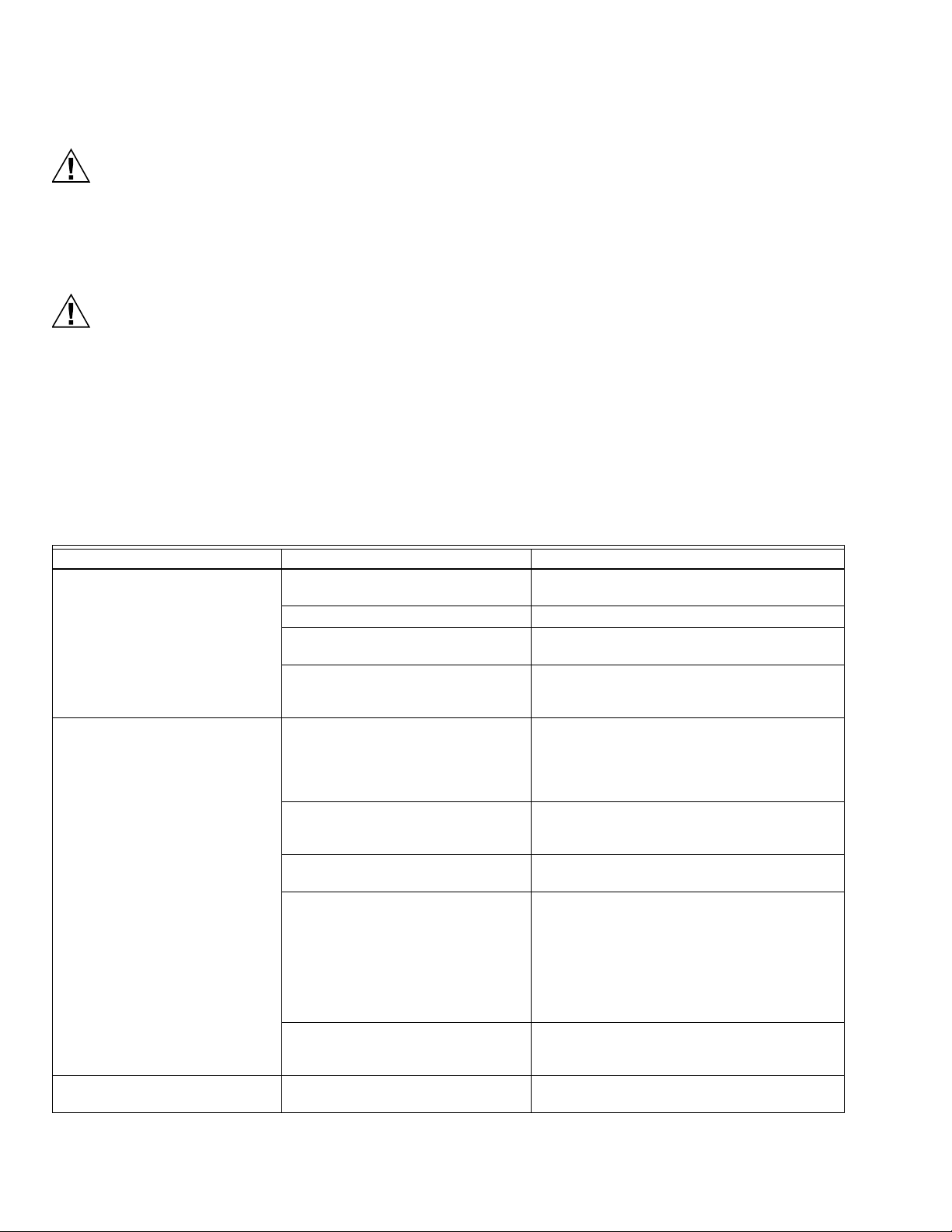
Symptom Cause Corrective Action(s)
Nothing happens when On/Off
switch is turned on.
Humidifier will not humidify or not
reaching HM700 setpoint
Humidifier has faulted and yellow
LED is flashing
Table 7. General troubleshooting.
Fuse blown Check inline fuse between transformer and
control board.
Incorrect Voltage Check voltage against spec label and correct.
Step Down Transformer not outputting
24VAC
Incorrect primary power jumper Check that jumper on high voltage terminal block
Safety loop open Check if there is 24 VAC at terminal 2.
No demand signal Check voltage between terminal 3 and 4. For
Capacity has been manually limited Check Manual Capacity adjustment
Low conductivity water Check if yellow LED is on. If operated on low
No airflow in duct Check that humidifier fan enable (terminals 19-20)
Software has detected an abnormal
condition
Replace the transformer.
is connected between P and terminal
corresponding to supply voltage. See Fig. 16.
Check wiring and operation of On/Off devices
connected to terminal 1 and 2.
Check jumper is installed in air proving safety
loop, terminal 1 and 8.
demand configuration 35% of full-scale signal
must be present for humidifier to start.
potentiometer. Clockwise increases capacity.
conductivity water it may take several hours for
the HM700 to reach full output capacity. This is
normal. During this time the humidifier will not
perform any drains and the conductivity of the
water in the cylinder will increase. Conductivity
can be increased more quickly by adding
1/4 teaspoon of salt.
are properly wired to furnace. Check air proving
wired to terminal 8.
Refer to Table 8 on page 22.
33-00118EFS—01 20
Page 21
HM700A1000
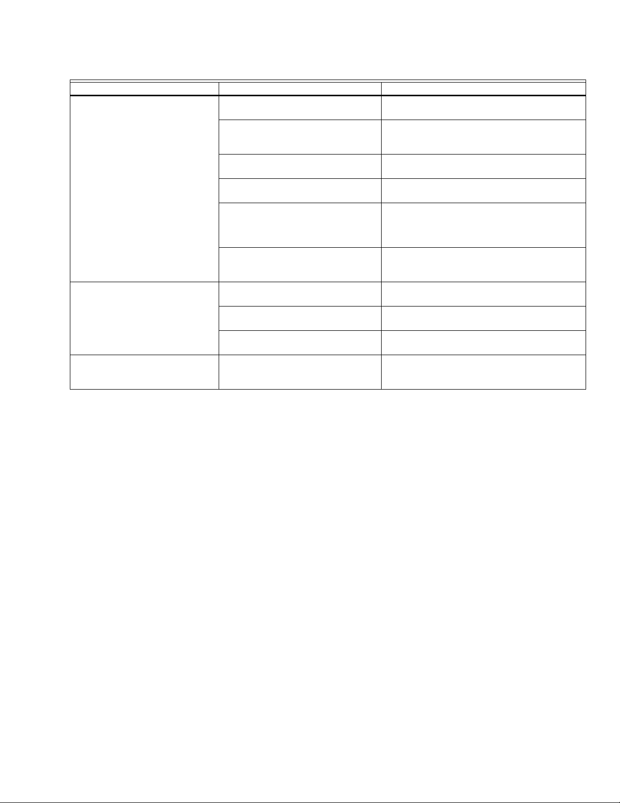
Table 7. General troubleshooting. (Continued)
Symptom Cause Corrective Action(s)
Distributor spitting out water Distributor not level Use support at end of distributor to ensure it is
level.
“P” Trap too close to distributor “P” Trap must be a minimum of 12 in (30 cm)
below the distributor to ensure flow. Relocate if
required.
Condensate line not sloped sufficiently Sufficient slope to ensure flow is required.
Reinstall if required.
Trap blocked Check that water flows through trap. Clear out if
blocked.
Steam line not insulated If steam line is long, condensate build up could
overload distributor condensate port. Insulate line
to improve efficiency and install additional
condensate traps as required.
Incorrect steam line installation Check that steam line has been installed with
condensate traps and slope. See “Steam Lines
and Condensate Return Instructions” on page 8.
Condensation in duct Installation clearances not observed Refer to distributor installation manual for required
clearances. Relocate distributor if required.
Design conditions changed Check supply air temperature and humidity to
determine if conditions have changed.
High limit not functioning Check setting and operation of high limit. Replace
if defective.
Humidifier is tripping the GFI. Humidifier is wired to a GFI circuit.
Drain valve ground wire is not
disconnected.
Review the Electrical Installation Steps and Notes
on page 10 for GFI guidelines and ground wire
removal information.
21 33-00118EFS—01
Page 22
HM700A1000
HM700 Faults
The self-diagnostic system built into the HM700 is continually
monitoring the operation of the humidifier. When an abnormal
condition occurs that cannot be self-corrected by the software
the HM700 will turn off power to the cylinder, drain the
cylinder, and annunciate the fault using the yellow status LED.
LED Flash Sequence
To differentiate between different fault conditions the yellow
LED is flashed in different sequences. Table 8 lists the fault
sequences that can be displayed, their meaning, possible
cause and suggested corrective actions.
Clearing a Fault
• Check the flash sequence against the list of fault messages
and take any necessary actions to correct the cause(s) as
outlined in Table 8 on page 22.
• Power cycle the humidifier with the On/Off switch waiting
10 seconds between turning it off and on.
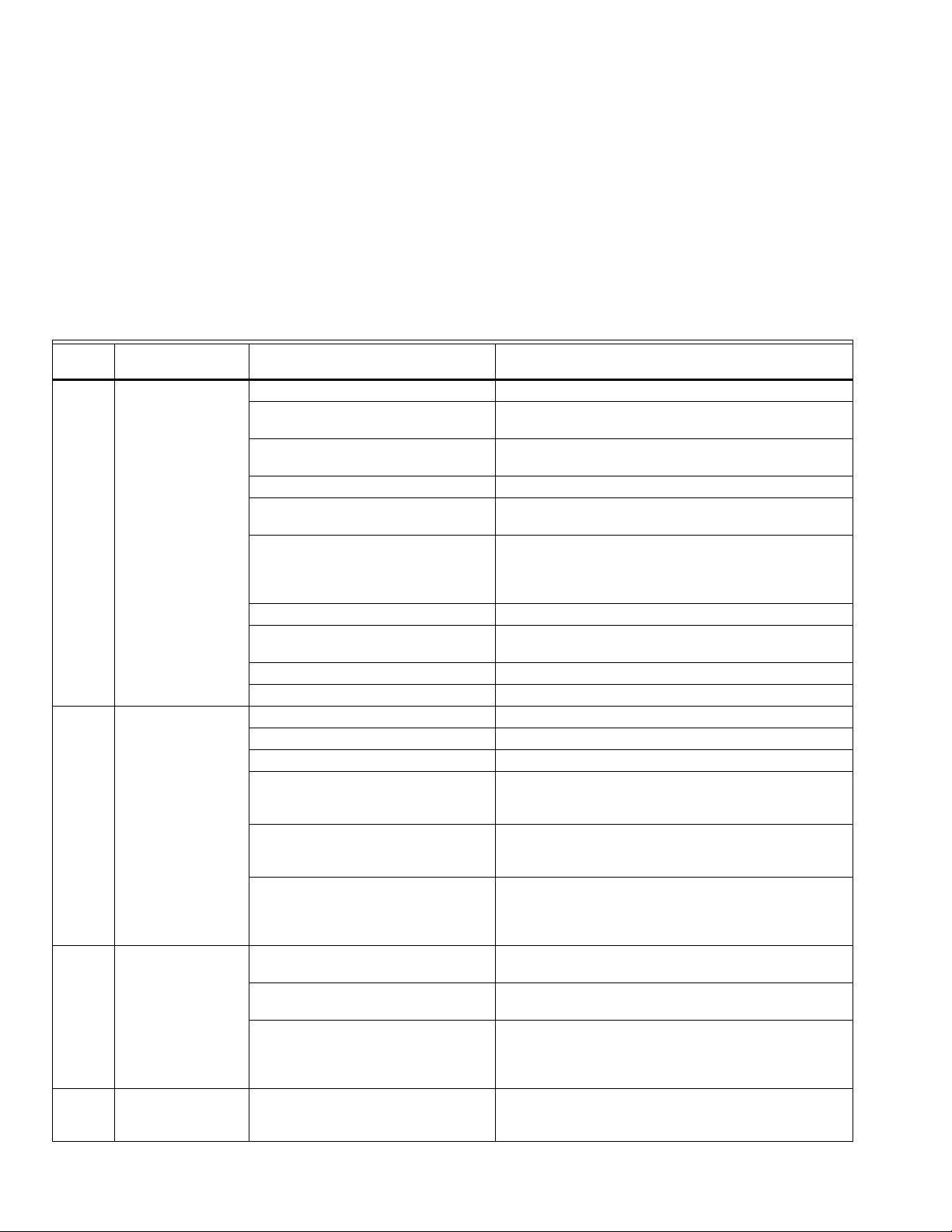
Table 8. Troubleshooting HM700 Faults.
Yellow
LED Symptom Cause Corrective Action(s)
1 flash Excess Current
Current has
exceeded 130% of
max
2 flashes No Current
Fill valve activated
for long time but
high water level not
reached.
Fill should be faster
than 1” per minute.
3 flashes No Current, High
Water
Water level at top of
cylinder with no
current
4 flashes Cylinder Spent
Electrodes covered
with scale.
Drain blocked water over concentrated Clean the drain line
Drain solenoid not energized, water
over concentrated
Filling too fast, fill valve damaged and
leaking
Filling too fast, wrong fill valve Fill valve may be defective - replace if necessary
Water supply too conductive a) Change the water supply
Humidifier short cycling a) Check if high limit or other On/Off control is cycling
Wrong cylinder installed Install correct cylinder model
Cylinder Spent but not detected by
software
Condensate from other source Remove condensate returns other than from steam line.
Back pressure Eliminate back pressure
Drain valve leaking or stuck open Clean drain valve or replace (see maintenance chapter)
Water shut off valve closed Open shut off valve
Fill Valve strainer blocked Clean out strainer on fill valve inlet.
High system back pressure a) Check for kinked hose
High water sensor not connected Check that cylinder plug with white marker is connected
Low water conductivity a) Check if potable water supplied to unit, not treated
Primary wire not looped through
current transformer.
High water sensor plug is on an
electrode pin.
Cylinder plugs installed incorrectly Check that cylinder plugs colors match markers next to
Cylinder electrodes are covered with
scale and humidifier cannot meet
demand
Check and correct wiring to drain valve.
Replace the fill valve
b) Contact Honeywell representative for recommendation
On/Off in less than 5 minutes. Check location and setting
of high limit.
b) Reduce the output by turning down the potentiometer
Replace the cylinder (see maintenance chapter)
b) Check for proper condensate removal (see
installation)
to short electrode with a plastic well around it and to
control board.
water (RO or DI).
b) Check conductivity of water. If less than 150 μS, add
1/4 teaspoon of salt to fill cup and restart unit.
Rewire primary wire through current transformer.
Install high water senor plug on cylinder pin with shroud
around it.
electrodes on cylinder and that white marked cylinder
plug is connected to short electrode located in plastic
well.
Replace cylinder with same model number (see
maintenance chapter).
33-00118EFS—01 22
Page 23
POTENTIOMETER
P8
HIGH WATER
K2
K3
P1 P2 P3 P4 P5 P6 P7
240/208/
120 VAC
24 VAC
1.5 AMPS
CYLINDER
FILL V
DRAIN V
1
2
3
4
8
19
20
21
R / HUM
AP
GF
RF
C
HUM
N/A
N/A
120L1
EXTERNAL
INTERNAL
240 P
ON/OFF/
DRAIN
SWITCH
TRANSFORMER
N/A
120L1
240 P
S
STATUS
LAMPS
G
Y
NOTE: INSTALL JUMPER FROM PTO TERMINAL
CORRESPONDING TO MAINS VOLTAGE.
HOT
NEUTRAL
GROUND
HOT
HOT
GROUND
240 VAC
120 VAC
NOTE:
DRY POINTS FOR FURNACE
FAN ENABLE.
24 V PILOT CONTROL ONLY
N/A
FACTORY INSTALLED TERMINAL
HUMIDITY
CONTROL
24V
HUM
CALL
M35721
HM700A1000
Fig. 26. Wiring diagram.
23 33-00118EFS—01
Page 24

HM700A1000
5 YEAR WARRANTY
Honeywell warrants this product to be free from defects in the workmanship or materials, under normal use and service, for a
period of five (5) years from the date of purchase by the consumer. If at any time during the warranty period the product is
determined to be defective or malfunctions, Honeywell shall repair or replace it (at Honeywell's option).
If the product is defective,
(i) return it, with a bill of sale or other dated proof of purchase, to the place from which you purchased it; or
(ii) call Honeywell Customer Care at 1-800-468-1502. Customer Care will make the determination whether the product should be
returned to the following address:
Honeywell Return Goods, Dock 4 MN10-3860, 1985 Douglas Dr. N., Golden Valley, MN 55422,
or whether a replacement product can be sent to you.
This warranty does not cover removal or reinstallation costs. This warranty shall not apply if it is shown by Honeywell that the
defect was caused by damage which occurred while the product was in the possession of a consumer.
Honeywell’s sole responsibility shall be to repair or replace the product within the terms stated above. HONEYWELL SHALL NOT
BE LIABLE FOR ANY LOSS OR DAMAGE OF ANY KIND, INCLUDING ANY INCIDENTAL OR CONSEQUENTIAL DAMAGES
RESULTING, DIRECTLY OR INDIRECTLY, FROM ANY BREACH OF ANY WARRANTY, EXPRESS OR IMPLIED, OR ANY
OTHER FAILURE OF THIS PRODUCT. Some states do not allow the exclusion or limitation of incidental or consequential
damages, so this limitation may not apply to you.
THIS WARRANTY IS THE ONLY EXPRESS WARRANTY HONEYWELL MAKES ON THIS PRODUCT. THE DURATION OF
ANY IMPLIED WARRANTIES, INCLUDING THE WARRANTIES OF MERCHANTABILITY AND FITNESS FOR A PARTICULAR
PURPOSE, IS HEREBY LIMITED TO THE FIVE-YEAR DURATION OF THIS WARRANTY.
Some states do not allow limitations on how long an implied warranty lasts, so the above limitation may not apply to you. This
warranty gives you specific legal rights, and you may have other rights which vary from state to state.
If you have any questions concerning this warranty, please write Honeywell Customer Care, 1985 Douglas Dr, Golden Valley, MN
55422 or call 1-800-468-1502.
IMPORTANT
To maintain warranty, only Honeywell approved parts and cylinders may be used in the operation of the product.
Automation and Control Solutions
Honeywell International Inc.
1985 Douglas Drive North
Golden Valley, MN 55422
customer.honeywell.com
® U.S. Registered Trademark
© 2016 Honeywell International Inc.
33-00118EFS—01 M.S. 03-16
Printed in United States
Page 25
HM700A1000
HUMIDIFICATEUR ELECTRODE STEAM
— Tuyau de vidange en caoutchouc
— Notice d'installation, Guide du propriétaire et Guide de
démarrage rapide
Outils requis
—Tournevis
— Clé
— Pinces
— Robinet de coupure d'eau
— Conduite d'eau (PEbd ou cuivre)
Configuration de l'humidificateur
Le modèle HM700 est configuré en usine pour fonctionner
dans la plupart des conditions sans avoir à modifier sa
configuration.
NOTICE D’INSTALLATION
INTRODUCTION
Le modèle HM700 est l'humidificateur à vapeur résidentiel le
plus sophistiqué du marché et fournit une humidification
résidentielle constante et fiable. L'humidificateur est conçu
pour être raccordé à un distributeur de vapeur installé dans un
conduit d'alimentation en air pour assurer une humidité à la
demande.
IMPORTANT
Lire et conserver ces instructions. Ce guide doit être
conservé par l'installateur, et le Guide du propriétaire
doit être laissé avec le propriétaire de l'équipement.
Inclus dans la boîte
— Humidificateur à vapeur (HM700)
— Nécessaire de distribution à montage à distance
(HM700ADISTKIT)
— Humidistat HumidiPRO (H6062A1000)
— Bouteille de vapeur (une bouteille HM700ACYL2
incluse)
Tableau 1. Spécifications.
Débit de
Référence de
pièce Volts
HM700A1000
110/120 11 1,4
220/240 22 2,8
vapeur en
gal./jour KW Ampères Phase
12,0 1 15 A CYL2
REMARQUE : L'humidificateur étant configuré en usine
pour produire des performances optimales,
Honeywell décourage vivement de modifier
les cavaliers ou le potentiomètre; cela
pourrait annuler la garantie et endommager
l'humidificateur. Contactez le service
clientèle de Honeywell pour de plus amples
informations.
Avant l'installation
1. Assurez-vous que la tension et la phase disponibles
correspondent à la tension et à la phase de
l'humidificateur indiquées sur l'étiquette des
spécifications de l'humidificateur.
2. Assurez-vous que le sectionneur à fusible externe dédié
est de taille suffisante pour gérer l'intensité nominale
indiquée sur l'étiquette des spécifications. Consultez les
codes locaux.
3. Assurez-vous qu'il y a suffisamment d'espace, tel que
décrit dans la section Emplacement à la page 5.
4. Assurez-vous que les conduites de vapeur peuvent être
acheminées vers distributeur, tel que décrit dans les
Instructions relatives aux conduites de vapeur et au
retour du condensat à la page 8.
Fusible
ext.
max.
Bouteille
standard
Poids
net/intégral
en lb (kg)
15 / 20
(7,0 / 9,5)
Dimensions en
pouces (L x l x H)
11,5 x 6,75 x 21,5
Page 26

HM700A1000
MISE EN GARDE
MISE EN GARDE
MISE EN GARDE
MISE EN GARDE
MISE EN GARDE
M35758
Golden Valley Minnesota 55422
MADE IN CANADA
MODEL:
VOLTS 1:
KW:
HM700A1000
S/N:
XXXXXXX
110-120
PHASE:
1
HZ:
60
1.4
DATE:
XXXXXXXXX
2583297A
220-240
VOLTS 2:
F.L.A: GPD:
12.0
F.L.A: GPD:
12.0
2.9
KW:
Auto-Adaptive
11
22
1
LISTED 205X
HUMIDIFIER
Fig. 1. Emplacement de l'étiquette des spécifications.
Entretien
Débranchez l’alimentation principale avant l’entretien.
Les compartiments de plomberie et d'électricité
contiennent des composants et des câbles haute
tension. L'accès doit être réservé au personnel
autorisé.
Pendant et après le fonctionnement de l'humidificateur,
la vapeur et les composants en contact avec la
vapeur tels que les conduites de vapeur, les
distributeurs de vapeur et les conduites de
condensats peuvent devenir brûlants et causer des
brûlures en cas de contact.
Honeywell n'accepte aucune responsabilité lorsque
les humidificateurs sont installés par un personnel
non qualifié ou lorsque des
pièces/composants/équipements non autorisés ou
approuvés par Honeywell sont utilisés.
Pour conserver la garantie, utilisez uniquement des
pièces et des bouteilles approuvées par Honeywell.
Électricité
Tous les travaux électriques doivent être effectués
conformément au code électrique local et national.
Les connexions électriques ne doivent être réalisées
que par un électricien qualifié.
L'unité doit être alimentée par un circuit muni d'un
disjoncteur de fuite à la terre dédié.
Plomberie
Les travaux de plomberie ne doivent être réalisés que
par un plombier qualifié.
L'eau qui sort de l'humidificateur peut être brûlante. Ne
la vidangez pas dans un évier public.
Tous les travaux de plomberie doivent être effectués
conformément au code de plomberie local.
Installation
Ne montez pas l'équipement sur des surfaces
chaudes.
Ne montez pas l'équipement dans des zones
soumises au gel.
Ne montez pas l'équipement sur des surfaces qui
vibrent.
Ne montez pas l'équipement sur le sol.
Le modèle HM700 produit de la vapeur à la pression
atmosphérique. Aucun appareil pouvant bloquer le
débit de vapeur ne doit être connecté à la sortie de
vapeur.
Les conduites de vapeur doivent être installées de
manière à ce qu'aucune restriction ne puisse
produire une contre-pression dans l'humidificateur.
Qualité de l’eau
Le modèle HM700 de Honeywell nécessite un
raccordement à l'eau froide provenant de
l'approvisionnement en eau principal du domicile
entre 30-100 psig. Une vanne d'étranglement peut
être nécessaire, et un robinet de coupure de l'eau
est recommandé pour la sécurité. N'utilisez pas
d'eau à osmose inverse ou déionisée. La
conductivité de l'eau est importante pour que
l'humidificateur à électrodes fonctionne
efficacement. Honeywell recommande 150-1200 μS
(microsiemens).
Pièces et accessoires
Les pièces et accessoires suivants sont nécessaires et sont
peut-être inclus avec l'humidificateur HM700. La bouteille est
le seul élément nécessitant un remplacement périodique pour
maintenir le bon fonctionnement de l'humidificateur.
Tableau 2. Pièces et accessoires.
Pièce/accessoire Référence de pièce
Bouteille de rechange HM700ACYL2
Humidistat HumidiPRO H6062A1000
Nécessaire de distribution à montage à distance en acier inoxydable HM700ADISTKIT
Vanne de vidange de rechange HM700ADVALVE
Vanne de remplissage de rechange HM700AFVALVE
Transformateur de rechange HM700ATX
Carte PC de rechange HM700APCB
Nécessaire de tuyau de conduite de condensat et de vapeur isolé de 15 pieds HM700AHOSEKIT
33-00118EFS—01 2
Contacteur de pression différentielle pour vérification de la présence d'air 50027910-001
Page 27

Fonctionnement de l’humidificateur
Le modèle HM700 est un générateur de vapeur
atmosphérique qui utilise la chaleur générée par le courant
électrique circulant entre les électrodes immergées pour
produire de la vapeur. Le modèle HM700 est conçu pour
l'humidification de l'air à la demande via un distributeur de
vapeur.
PRODUCTION DE VAPEUR
• Lorsque l'appareil reçoit un signal de demande et que la
boucle de sécurité entre les bornes 1 et 2 est fermée,
l'humidificateur ferme le contacteur et mesure le courant
électrique.
• Si la demande est inférieure à la production réelle, la
vanne d'admission est maintenue fermée et la production
est réduite en laissant le niveau d'eau dans la bouteille
diminuer par évaporation.
• Si la demande est supérieure à la production réelle, la
vanne de remplissage est activée après un bref délai et
l'eau pénètre dans la cuvette de remplissage. L'eau de la
cuvette de remplissage s'écoule dans le bas de la bouteille
par un tuyau connecté au carter de la vanne de vidange.
REMARQUE : La bouteille est alimentée par gravité
depuis la cuvette de remplissage. Si la contre-pression de la conduite de vapeur est
trop élevée, l'eau est renvoyée dans la
cuvette de remplissage et s'écoule par la
conduite de trop-plein jusqu'au drain.
• Dès que l'eau dans la bouteille entre en contact avec les
électrodes activées, le courant circule à travers l'eau. La
résistance de l'eau à la charge électrique génère de la
chaleur puis de la vapeur. Le courant électrique (et la
production de vapeur) augmente au fur et à mesure que le
niveau de l'eau augmente, au fur et à mesure de
l'immersion de l'électrode. L'unité continue de se remplir
jusqu'à ce que le courant corresponde à la demande ou
que le capteur de niveau d'eau élevé détecte un haut
niveau d'eau.
• Le modèle HM700 recommence le cycle de remplissage et
de condensation jusqu'à ce que la production corresponde
à la demande.
• Au fil du temps, les minéraux dans l'eau adhèrent aux
électrodes de la bouteille. L'humidificateur se remplit
automatiquement à un niveau d'eau supérieur pour
maintenir la pleine capacité pendant la durée de vie de la
HM700A1000
bouteille. À la longue, la formation de tartre empêchera
l'humidificateur d'atteindre sa pleine capacité. Le logiciel
HM700 surveille cet état et une fois détecté, le
fonctionnement s'arrête et le voyant jaune clignote à une
séquence répétitive de 4 clignotements.
VIDANGES
• La vapeur produit des minéraux qui augmentent la
conductivité de l'eau. Le cycle auto-adaptatif breveté du
système HM700 surveille la conductivité de l'eau et
effectue des vidanges pour maintenir l'eau à un niveau de
conductivité optimal et assurer une performance de pointe.
• Le cycle auto-adaptatif garantit que la durée de vie de la
bouteille est maximisée. Il procède en maintenant un strict
contrôle et une utilisation optimale de l'eau pendant toute
la durée de vie de la bouteille.
DISTRIBUTION DE VAPEUR
La vapeur produite par l'humidificateur peut être introduite
dans l'air de plusieurs manières. La méthode d'ajout de
vapeur dans l'air la plus courante consiste à monter un tube
distributeur de vapeur dans un conduit d'arrivée d'air.
CONDUITE DE VAPEUR
La conduite de vapeur entre la sortie de vapeur de la bouteille
et le distributeur remplit deux fonctions : elle est utilisée
comme conduit pour transférer la vapeur atmosphérique de
l'humidificateur au distributeur, ainsi que pour fournir un
moyen d'éliminer le condensat. Voir « Instructions relatives
aux conduites de vapeur et au retour du condensat » à la
page 8 pour plus d'informations sur la sélection de conduites
de vapeur.
RETOUR DU CONDENSAT
Lorsque de la vapeur est distribuée, un condensat se forme
dans le système de distribution. L'isolation des conduites de
vapeur est une méthode efficace permettant de réduire la
formation de condensat. Les conduites de vapeur sont
inclinées pour que le condensat ne se recueille pas dans les
conduites et ne restreigne pas le débit de vapeur. Le
condensat doit être recueilli et éliminé du système afin qu'il ne
s'accumule pas pour passer dans le conduit. Le condensat
peut être retourné à la cuvette de remplissage du système
HM700 pour réduire le gaspillage de l'eau, ou il peut être
vidangé.
3 33-00118EFS—01
Page 28

HM700A1000
(EN OPTION)
1 - R/HUM
2 - HUM
3 - C
4 - N/A
8 - AP
19 - Gf
20 - Rf
21 - N/A
CONDUITE
D'EAU
1/8 NPT À 1/4
COMPRESSION
OU PEBD
HM700
OFF
ON
DISJONCTEUR
OU
SECTIONNEUR
DÉDIÉ
EAU POTABLE FROIDE, 30-100 PSIG, 1/2 PO MIN.
REMARQUE : CONNEXION 240 V ILLUSTRÉE
EXTERNE
MF35805
24 (610)
HAUTEUR MIN.
36 (914)
MIN.
VIS 2 (51)
12 (305)
MIN.
MONTAGE
DISTRIBUTION
DE VAPEUR
RÉGULATEURS
RACCORDEMENT
DE PLOMBERIE
RACCORDEMENT
ÉLECTRIQUE
2 (51)
MIN.
12 (305)
TERRE
DIMENSIONNEMENT
IMPORTANT
Étanchéité supérieure 3,3 4,3 5,4 7,5 9,6 11,7 16
Étanchéité moyenne 7,6 9,6 11,8 16 20,3 24,4 33
Étanchéité inférieure 11,7 14,9 18,1 24,5 30,8 37,1 50
Fig. 2. Installation typique du modèle HM700.
Mesures en po (mm).
Le modèle HM700 produit 11 gallons par jour (gal./jour)
Le modèle HM700 ne doit être installé que s'il a été
correctement dimensionné. N'utilisez pas une
mesure en pieds carrés pour dimensionner une
installation avec humidificateur. Utilisez une
mesure en pieds cubes, car l'humidité remplit un
volume d'espace (largeur x longueur x hauteur).
Considérez également l'étanchéité de la construction
de l'habitation.
lorsqu'il fonctionne sur 120 V et 22 gallons par jour lorsqu'il
fonctionne sur 240 V. Voir la Figure 16 pour plus de détails sur
la configuration du modèle HM700 pour une tension
différente.
Le Tableau 3 contient des recommandations de l'AHRI
(Institut de climatisation, chauffage et réfrigération) en matière
d'humidité et le Tableau 4 montre les humidificateurs et la
configuration de sortie qui satisfont au exigences
d'humidification.
Tableau 3. Humidité recommandée par l'AHRI (Institut de climatisation, chauffage et réfrigération) (en gallons/jour).
Type de
construction 8000 pi
3
12 000 pi316 000 pi320 000 pi324 000 pi328 000 pi332 000 pi
3
33-00118EFS—01 4
Page 29

HM700A1000
Tableau 4. Humidificateur(s) à vapeur nécessaire(s) à l'application.
Type de
construction 8000 pi
Étanchéité
supérieure
Étanchéité
moyenne
Étanchéité
inférieure
a
Dans le tableau ci-dessus, 11 gallons/jour indique un humidificateur à vapeur configuré pour fonctionner sur 120 V et
11 gallons/jour 11 gallons/jour 11 gallons/jour 11 gallons/jour 11 gallons/jour
11 gallons/jour 11 gallons/jour 22 gallons/jour 22 gallons/jour 22 gallons/jour
22 gallons/jour 22 gallons/jour 22 gallons/jour
3
12 000 pi316 000 pi
3
20 000 pi
11 gallons/jour (x3)
ou
22 gallons/jour (x2)
3
24 000 pi
11 gallons/jour (x3)
22 gallons/jour (x2)
3
11 gallons/jour (x2)
22 gallons/jour (x1)
11 gallons/jour (x3)
22 gallons/jour (x2)
11 gallons/jour (x4)
ou
22 gallons/jour (x2)
a
28 000 pi
ou
ou
ou
3
32 000 pi
11 gallons/jour (x2)
22 gallons/jour (x1)
11 gallons/jour (x3)
22 gallons/jour (x2)
11 gallons/jour (x5)
22 gallons/jour (x3)
ou
ou
ou
22 gallons/jour indique un humidificateur à vapeur configuré pour fonctionner sur 240 V.
EMPLACEMENT
Montez sur une surface horizontale ou verticale adaptée. Ne
REMARQUE : Ne montez pas l'appareil sur des surfaces
chaudes ou soumises au gel ou à des
vibrations, ni sur le sol.
posez pas l'unité sur le sol. Allouez les dégagements requis
pour les raccordements de plomberie et électriques. Les
dimensions des dégagements sont indiquées à titre de
référence uniquement et constituent le minimum requis pour
l'entretien de l'humidificateur. Consultez les codes locaux et
nationaux avant de déterminer l'emplacement final et de
procéder à l'installation. Honeywell n'accepte aucune
responsabilité en cas de violations du code d'installation.
• Installez uniquement dans des zones à température
ambiante de 41 à 104 °F (5 à 40 °C) et humidité relative de
5 à 95 %.
• Dans la mesure du possible, installez sous le distributeur
de vapeur. Prenez soin de bien acheminer la conduite de
vapeur et d'utiliser des purgeurs de condensat adéquats.
• Placez l'humidificateur LE PLUS PRÈS POSSIBLE du
distributeur de vapeur. Plus l'humidificateur est éloigné,
Montage avec boutonnières
1. L'humidificateur HM700 peut être monté sur un mur en
utilisant la boutonnière située à l'arrière de l'armoire de
l'appareil.
2. Utilisez des vis n°8 x 2 po (5 cm) installées dans des
montants de 2x4 po ou plus. Deux vis sont requises,
une pour suspendre l'unité, et l'autre pour la fixer de
manière à ce qu'elle ne se relève pas dans la
boutonnière.
3. Installez la vis supérieure de manière à en exposer
1/4 po (6 mm). Relevez l'unité et placez la tête de vis
dans la boutonnière.
4. Assurez-vous que l'unité est à niveau puis insérez et
serrez la deuxième vis dans la boutonnière. Serrez la
vis supérieure. Voir la Fig. 3.
plus la production sera réduite en raison de la perte
thermique qui a lieu dans la conduite de vapeur.
• Lorsque c'est possible, montez l'humidificateur HM700 à
une hauteur qui facilitera l'entretien.
REMARQUE : Utilisez des vis d'une longueur supérieure à
2 po (5 cm) si une cloison sèche ou une
autre entretoise est présente.
3
BOUTONNIÈRE
TROU
INSÉREZ UNE VIS
EN LAISSANT
1/4 PO (6 MM)
DÉPASSER.
ACCROCHEZ L'UNITÉ
PUIS SERREZ LA VIS.
INSTALLEZ UNE
DEUXIÈME VIS
APRÈS AVOIR
ACCROCHÉ
L'HUMIDIFICATEUR
VIS À BOIS N° 8 x 2 PO (5 CM)
Fig. 3. Montage avec boutonnières.
5 33-00118EFS—01
MONTANT 2x4 PO
OU AUTRE MEMBRE
DE CHARPENTE
MF35759
Page 30

HM700A1000
M35855
PLOMBERIE
UTILISEZ UN RACCORD À COMPRESSION
DE 1/4 PO (INCLUS) POUR RACCORDER LA
CONDUITE D'ARRIVÉE D'EAU À L'UNITÉ
(PLASTIQUE PEBD OU CUIVRE).
DIA. EXT. 1/2 PO (30 MM)
INSTALLEZ TOUJOURS UN
ROBINET DE COUPURE D'EAU.
1
LES CONDUITES DE REMPLISSAGE ET
1
DE VIDANGE PEUVENT AUSSI ÊTRE
ACHEMINÉES PAR L'OUVERTURE À
L'ARRIÈRE DE L'ARMOIRE.
Fig. 4. Raccords d’arrivée et de vidange d’eau.
IMPORTANT
— Tous les raccords des conduites d'arrivée et de
vidange d'eau doivent être installés conformément
aux codes de plomberie locaux.
— L'eau de vidange est automatiquement refroidie à
140 °F (60 °C) lorsque l'humidificateur HM700 est en
mode de vidange. Lorsque la commande de vidange
manuelle est utilisée, la température peut être
supérieure. Le matériau du tube et du drain doit être
compatible avec une température de 200 °F (93 °C).
• L'eau de distribution doit être entre 30 et 100 PSIG. Une
vanne d'étranglement peut être utilisée si nécessaire.
• N'utilisez pas d'eau à osmose inverse ou déionisée. L'eau
fournie doit être entre 150-1200 μS (microsiemens) pour
une conductivité optimale.
UTILISEZ UNE CONDUITE EN CUIVRE DE
1/2 PO DANS LES 4 PIEDS (1,2 M) DE L'HUMIDIFICATEUR.
MF35760
• L'eau fournie doit être froide, de 34 à 68 °F (1 à 20 °C).
• Installez le robinet de coupure d'eau avant l'humidificateur
pour faciliter l'entretien.
• La conduite de vidange ne doit pas se terminer dans un
évier fréquemment utilisé ou non autorisé par les codes de
plomberie. Acheminez une conduite de vidange au sol ou
un équivalent pour des raisons de sécurité.
• Pour permettre l'eau de circuler librement, s’assurer que la
conduite de vidange ait une pente suffisante,
n’emprisonne pas l’eau, et ne fasse pas de nœuds. Un
écoulement limité peut causer une concentration d'eau
excessive et un fonctionnement inadéquat.
• Si un système de drainage n'est pas situé près de
l'humidificateur, utilisez une pompe de condensat
compatible avec l'eau de vidange chaude.
Fig. 5.
33-00118EFS—01 6
Page 31

Distribution de vapeur
MF35756
1 TOUR
1
2
3
+45˚
–45˚
MF35764
DÉBIT D’AIR
1/3
2/3
Le modèle HM700 nécessite un distributeur de vapeur installé
du côté approvisionnement de la tuyauterie. L'humidificateur
HM700 peut distribuer de la vapeur dans une gaine de
ventilation en utilisant le distributeur indiqué dans le
Ta bl ea u 5 .
Tableau 5. Distributeur de vapeur.
Référence de pièce Description Remarques
Inclut un distributeur de vapeur, une conduite de vapeur isolée de 5
pieds, une conduite de condensat et la visserie d'installation.
HM700ADISTKIT
Nécessaire de distribution à
montage à distance en acier
inoxydable
Le distributeur de vapeur doit être installé aussi près que
possible de l'humidificateur. Les conduites de distribution de
vapeur courtes réduisent la perte de condensat et le risque de
contre-pression dans la conduite de distribution de vapeur.
HM700A1000
H
1/3 DE LA
LARGEUR
1/3 DE LA
LARGEUR
Fig. 8. Distributeur installé horizontalement
1/3 DE LA
LARGEUR
LARGEUR
2/3 DE LA
LARGEUR
1/3 DE LA
LARGEUR
dans un conduit horizontal.
DÉBIT D’AIR
MIN. L=8 (203)
MF35755
Fig. 6.
1/3
2/3
MF35765
Fig. 9. Distributeur installé horizontalement dans un
conduit vertical. Faites tourner le distributeur de 45° pour
que la vapeur soit déchargée vers le centre de la gaine, en
direction du débit d'air.
DÉBIT D’AIR
MF35766
Fig. 10. Distributeur installé verticalement
dans un conduit horizontal.
Cette configuration n'est pas recommandée.
Fig. 7.
7 33-00118EFS—01
Page 32
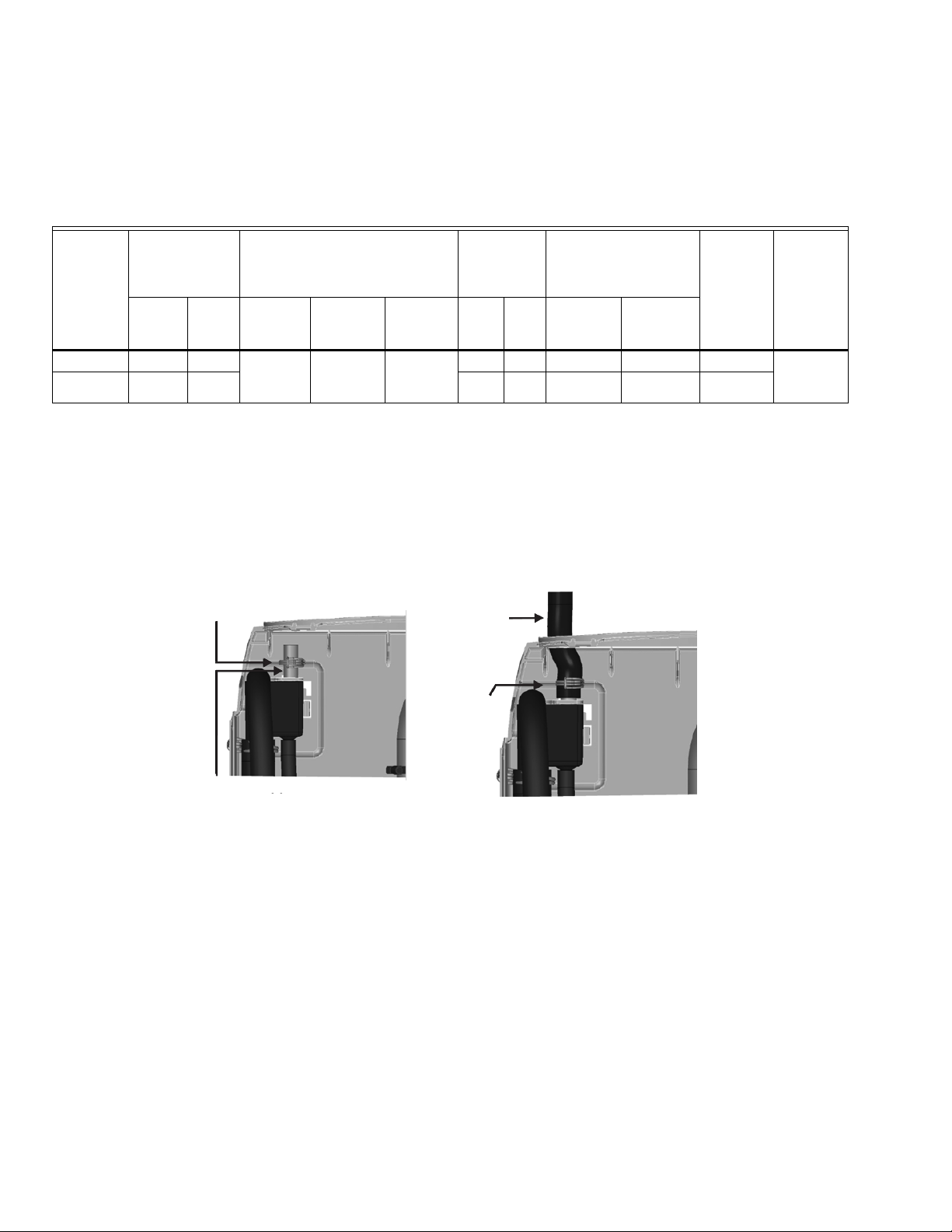
HM700A1000
MF35761
BRIDE À RESSORT
TUBE EN CUIVRE DE 3/8 PO DE DIA. EXT.
BRIDE À
RESSORT
INSÉREZ LE TUYAU
SUR LE TUBE EN
CUIVRE ET SERREZ
AVEC LA BRIDE À
RESSORT
Instructions pour les conduites de vapeur et le retour de condensat
Les instructions suivantes doivent être suivies lors de l'installation des conduites de vapeur de l'humidificateur HM700. Si le
matériel recommandé n'est pas utilisé, si la longueur maximum recommandée dans le Tableau 6 est dépassée, ou si les autres
instructions d'installation des conduites de vapeur ne sont pas suivies, l'humidificateur pourrait mal fonctionner et la garantie
pourrait être annulée.
Tableau 6. Recommandations relatives aux conduites de vapeur pour le conduit de l'humidificateur HM700.
Longueur
maximum de
la conduite de
vapeur Pertes possibles
7 (2) 0,5 (0,2) 115
Débit d’air
minimum
(pi3/m)
Pression
statique
max.lb/h (kg/h)
3,0 po c.e
Tube en
L
*
Tub e en
acier
inoxydable pieds (m) lb/h (kg/hr)
0,875 x
0,049 de
large
Débit de vapeur Matériel
Tension
Tuy au de
vapeur
cuivre MED-
110/120V 3,85 (1,75)
220/240V 7,7 (3,5) 12 (3.5) 1,5 (0,7) 230
7/8 po 3/4 po
* L'utilisation d'une conduite de vapeur autre qu'un tube en cuivre, en acier inoxydable ou fourni par Honeywell pourrait annuler la
garantie et compromettre le fonctionnement de l'humidificateur.
* Si un tube en cuivre ou acier inoxydable (autre que le tube fourni) est utilisé, il est recommandé de l'isoler pour assurer la
sécurité à haute température et réduire le condensat.
Pour assurer le retour du condensat, insérez un tube en cuivre (fourni avec l'équipement) à mi-chemin dans l'ouverture de
condensat de la cuvette de remplissage avec la bride à ressort (fournie avec l'équipement).
Insérez le tuyau de condensat dans l'orifice de retour du condensat en haut de l'humidificateur HM700 et sur le tube en cuivre.
Fixez en position avec la bride à ressort.
Fig. 11. Retour du condensat.
RÈGLES PRINCIPALES POUR LES CONDUITES DE VAPEUR ATMOSPHÉRIQUES
• Les conduites de vapeur ne doivent comporter aucune obstruction pouvant créer une contre-pression.
• Respectez les matériaux, les dimensions et les longueurs recommandés. Consultez les tableaux.
• Installez la conduite de vapeur verticalement (vers le haut) de l'humidificateur HM700 à la buse de distribution. Consultez les
Figures 12-14 pour les autres options d'installation.
• Isolez avec 1,0 po (2,5 cm) d'isolant pour tuyau.
• Purgez le condensat (utilisez un T de taille intégrale pour les purgeurs)
• Ne serrez pas trop la bride du tuyau au niveau de la sortie de vapeur de la bouteille. Le couple maximum est 12 po-lb.
• Soutenez la conduite de vapeur pour que le poids ne soit pas sur la bouteille.
• Les purgeurs de condensat doivent avoir une hauteur minimum de 6 po (15 cm) ou une pression statique de conduit de +2 po
(5 cm), minimum, la valeur supérieure devant être retenue.
• Purge par purgeur P ou queue de cochon. Soutenez la conduite selon le besoin pour qu'elle soit exemple de pliures.
33-00118EFS—01 8
Page 33
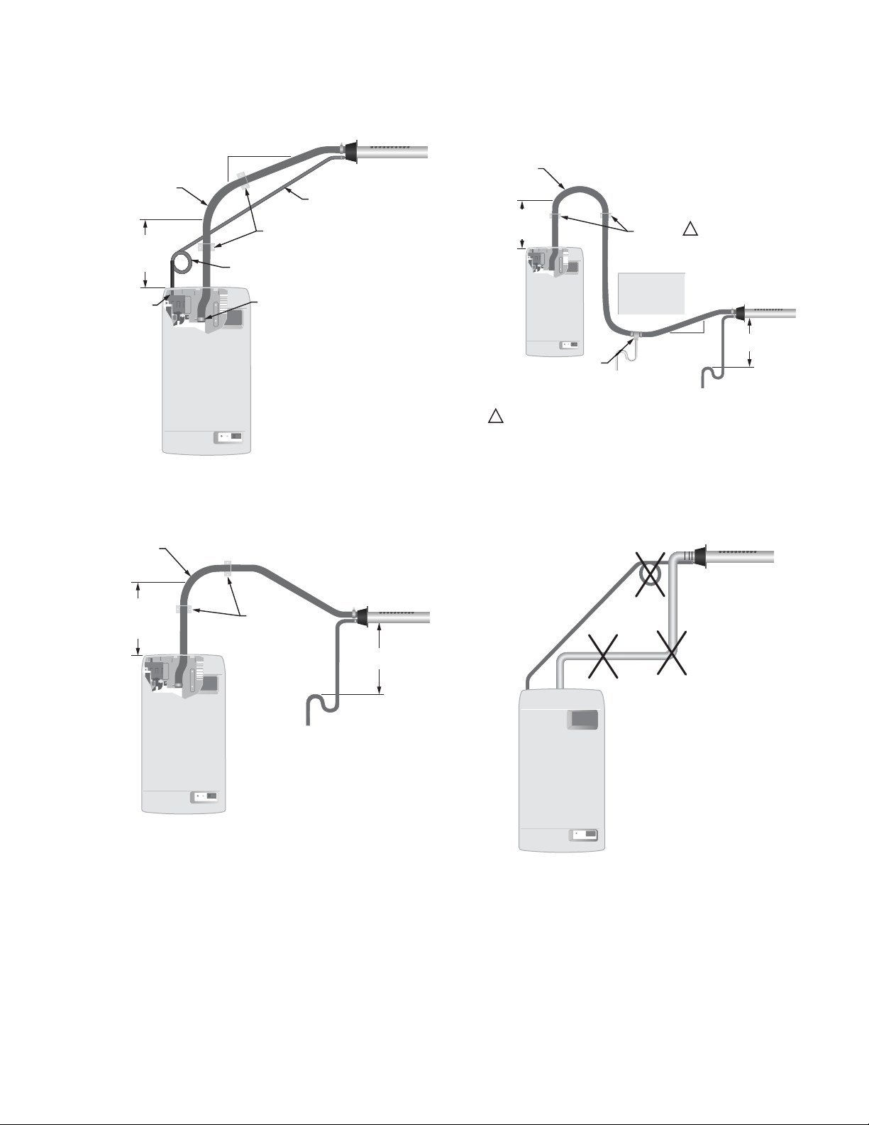
Exemples d'installation de conduite de vapeur
MF35717
CONNECTEZ
LE TUYAU DE
CONDENSAT À
LA CUVETTE DE
REMPLISSAGE
12 (305)
MINIMUM
AVANT TOUTE
COURBURE
RAYON
MINIMUM
12 (305)
CONDUITE
DE CONDENSAT
SUPPORTS
DE RETENUE
12 (305)
2 (51)
MINIMUM
CONNECTEZ LE
TUYAU DE VAPEUR
À LA BOUTEILLE
CONDUITE DE
CONDENSAT
MF35720
PAS DE PURGEUR
DE CONDENSAT AU
NIVEAU DE LA
TRANSITION
VERTICALE
CONDUITE DE
VAPEUR NON INCLINÉE
PURGEUR DE CONDENSAT
NON SITUÉ À 12 (305)
SOUS LE
DISTRIBUTEUR
RAYON
MINIMUM
12 (305)
12 (305)
MINIMUM
AVANT TOUTE
COURBURE
UTILISEZ UN T DE CONDENSAT DE
TAILLE INTÉGRALE AU NIVEAU DU
POINT BAS. INCLINEZ LES
CONDUITES VERS LE HAUT
JUSQU'AU T IMMÉDIATEMENT APRÈS.
LE TUYAU S'ASSOUPLIT AVEC LE TEMPS. UN SUPPORT ADÉQUAT EST REQUIS.
1
SUPPORTS
DE RETENUE
OBSTRUCTION
VERS ÉVACUATION
1
12
(305)
2 (51)
MIN.
MINIMUM
VERS ÉVACUATION
HM700A1000
12 (305)
MINIMUM
MF35719
Fig. 12. Distributeur à vapeur au-dessus de
l'humidificateur (tuyau). Mesures en po (mm).
RAYON
MINIMUM
12 (305)
12 (305)
MINIMUM
AVANT TOUTE
COURBURE
SUPPORTS
DE RETENUE
PURGEUR DE
CONDENSAT
VERS ÉVACUATION
Fig. 13. Distributeur à vapeur en dessous de
l'humidificateur (tuyau). Mesures en po (mm).
12 (305)
MINIMUM
Fig. 14. Distributeur à vapeur en dessous de
l'humidificateur avec obstruction (tuyau).
Mesures en po (mm).
MF35718
Fig. 15. Erreurs courantes lors de l'installation de la
conduite de vapeur. Mesures en po (mm).
9 33-00118EFS—01
Page 34
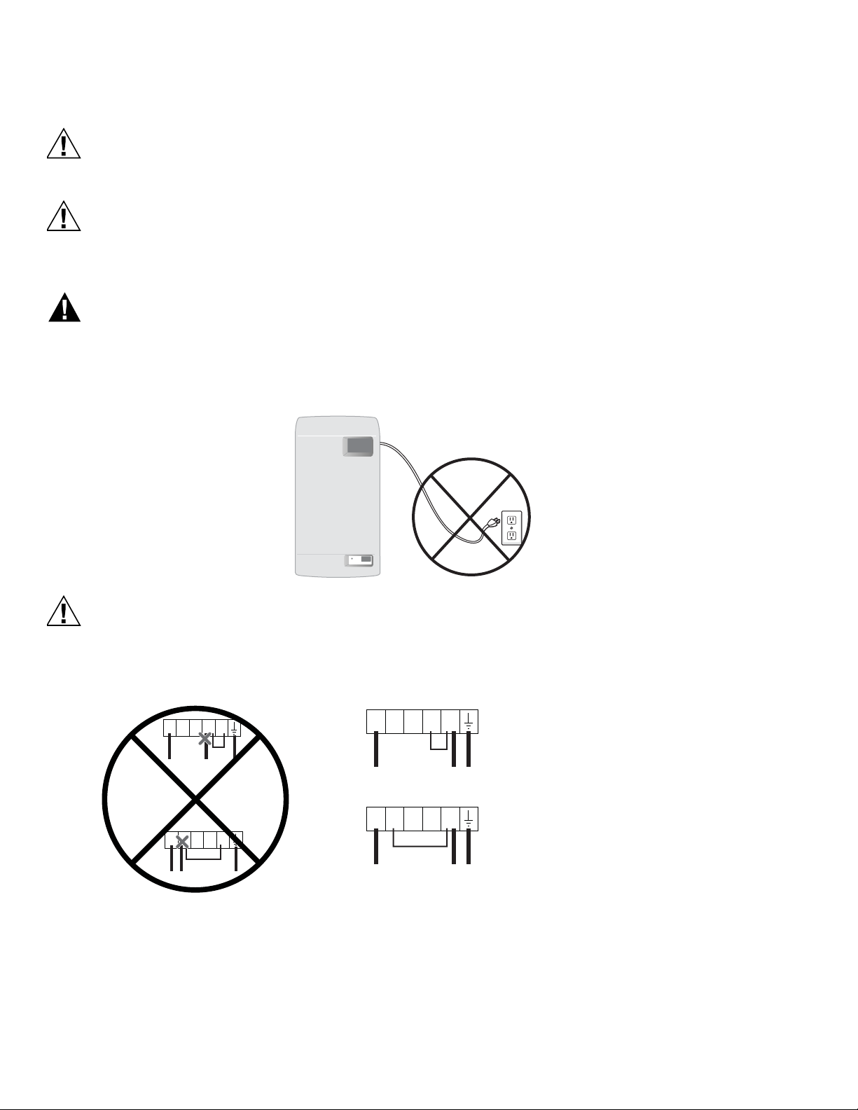
HM700A1000
MISE EN GARDE
MISE EN GARDE
AVERTISSEMENT
MISE EN GARDE
M35779
240 VAC
L1 N/A P120 240
120 VAC
Hot
Hot
Jumper
L1 N/A P120 240
Hot
Neutral
Ground Ground
Jumper
240 VAC
L1 N/A P120 240
120 VAC
Hot
Hot
Jumper
L1 N/A P120 240
Hot
Neutral
Ground
Ground
Jumper
M35850
INSTALLATION ÉLECTRIQUE
Le câblage doit être réalisé par un électricien qualifié. L'unité doit être installée sur un circuit muni d'un
disjoncteur de fuite à la terre.
Risque de dégât matériel
Un câblage non conforme aux instructions de câblage peut causer des dégâts permanents.
De telles erreurs pourraient annuler la garantie.
L’humidificateur HM700A doit être relié à un disjoncteur de 15 A qui lui est réservé et auquel il est directement
câblé pour que l’installation soit conforme à l’homologation UL du produit. Tout le raccordement électrique doit
être fait conformément aux codes de l’électricité.
Les cordons d’alimentation électrique peuvent surchauffer et provoquer des dégâts matériels ou des blessures.
Remarque : En cas de non-respect des présentes directives, la garantie sera nulle.
INSTALLATION DU FIL DE RACCORDEMENT
• NE PAS installer les fils d’alimentation (vivant et neutre) dans les bornes 120 et 240.
• Installer les fils d’alimentation dans les bornes L1 (vivant) et P (vivant/neutre).
• Installer un fil de raccordement (pontage) entre la borne P et la borne 120 ou 240 (selon la tension d'alimentation).
Étapes de l'installation
1. L'unité nécessite un circuit dédié protégé par un disjoncteur de fuite à la terre. Un sectionneur doit être installé à proximité
2. Câblez l'humidificateur sur le sectionneur comme illustré à droite.
du circuit pour assurer une protection contre les chocs électriques durant l'entretien.
3. Installez un cavalier fourni par l'usine entre la borne P et la borne correspondant à la tension d'alimentation.
4. Retirez le fil vert attaché au corps du boîtier et à la vanne de vidange (retirez la cartouche pour faciliter l'accès).
5. Accrochez le fil de terre aussi près que possible de la vanne de vidange et coupez l'excédent.
33-00118EFS—01 10
Page 35
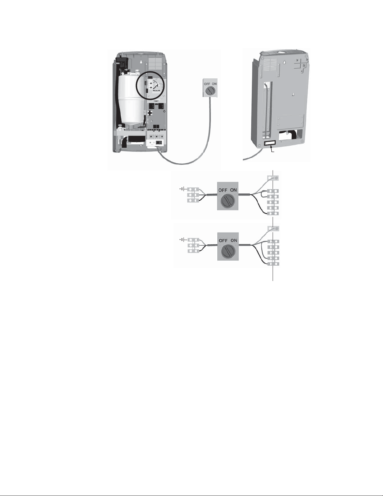
HM700A1000
SOUS TENSION
SOUS TENSION
TERRE
P
240
120
L1
TERRE
E
X
T
I
N
T
240 V c.a. (1 PHASE)
120 V c.a. (1 PHASE)
NEUTRE
SOUS TENSION
TERRE
P
240
120
L1
TERRE
REMARQUE : CONNECTEZ LE FIL
SOUS TENSION DE
120 V C.A. À L1.
(EN OPTION)
(EN OPTION)
REMARQUE : LES FILS D'ALIMENTATION
PEUVENT AUSSI ÊTRE ACHEMINÉS PAR
L'OUVERTURE À L'ARRIÈRE DE L'ARMOIRE.
MF35806
Fig. 16. Connexion d'alimentation principale.
REMARQUES :
— Honeywell requiert l'utilisation d'un circuit muni d'un disjoncteur de fuite à la terre sur cet appareil pour protéger le
propriétaire des chocs électriques.
— Lorsque l'installation est correcte, le fil vert doit être retiré de la vanne de vidange. Le fil vert est préinstallé en usine
pour protéger le propriétaire en cas d'installation incorrecte ou lorsqu'il n'est pas possible d'installer après coup un
circuit avec disjoncteur de fuite à la terre. Voir la Fig. 24 pour l'emplacement du fil vert sur la vanne de vidange.
— Assurez-vous qu'une alimentation adéquate est disponible pour supporter l'ampérage maximum de l'humidificateur
indiqué sur l'étiquette des spécifications.
— N'utilisez pas le fil neutre comme fil de terre. Branchez un fil de terre dédié sur la borne de terre.
— Tout le câblage doit être réalisé conformément aux codes électriques nationaux et locaux.
11 33-00118EFS—01
Page 36
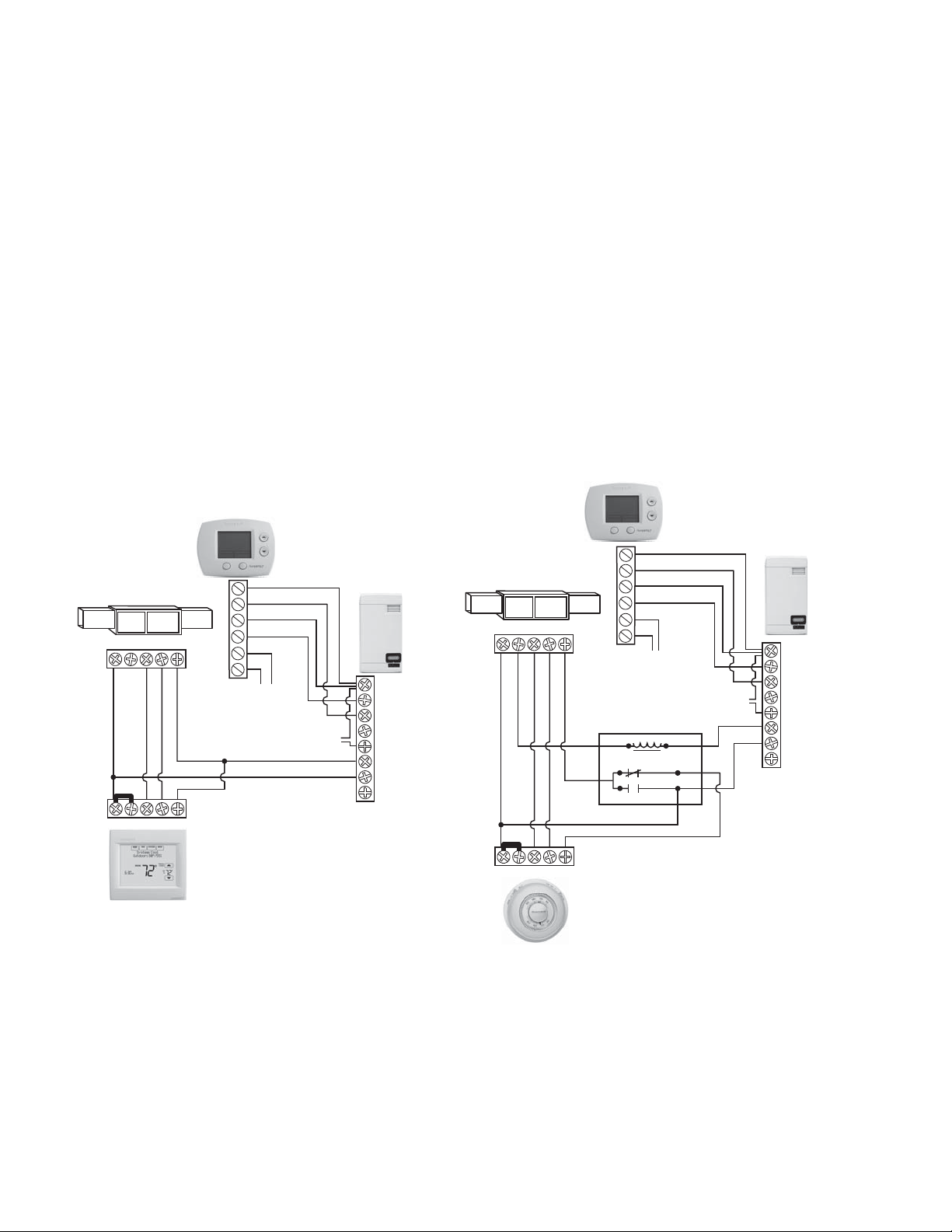
HM700A1000
CVCA
THERMOSTAT
R
C
U
U
S
S
GYWRRc
GYWR C
R/HUM
HUM
C
S. O.
AP
G
F
R
F
S. O.
MF35754
CAPTEUR
EXTÉRIEUR
DISPOSITIF DE VÉRIFICATION
DE PRÉSENCE D'AIR OU CAVALIER
CVCA
THERMOSTAT
R
C
U
U
S
S
GYWRRc
GYWR C
R/HUM
HUM
C
N/A
AP
G
F
R
F
N/A
MF35730
CAPTEUR
EXTÉRIEUR
RELAIS UNIPOLAIRE BIDIRECTIONNEL
COM
NF
NO
DISPOSITIF DE VÉRIFICATION
DE PRÉSENCE D'AIR OU CAVALIER
REMARQUE : UN RELAI UNIPOLAIRE BIDIRECTIONNELLE
EST NÉCESSAIRE POUR EMPÊCHER D'ACTIONNER LA
BORNE Y SI LE THERMOSTAT N'ISOLE PAS Y ET G.
RÉGULATEURS EXTERNES
Câblage de verrouillage du ventilateur avec HumidiPRO
Lorsque la vapeur est distribuée dans un conduit, il doit y avoir
une demande d'humidité en l'absence de débit d'air.
L'humidificateur HM700 avec régulateur HumidiPRO ou un
autre thermostat (tel que Prestige ou VisionPRO
Honeywell) peut être utilisé pour actionner un ventilateur en
cas de demande d'humidité. Si un autre thermostat est utilisé,
consultez le manuel correspondant pour connaître les
instructions de câblage permettant d'actionner le ventilateur
avec un humidificateur électrique.
REMARQUE : L'humidificateur ne commence pas la
production de vapeur tant que la boucle de
sécurité du ventilateur n'est pas fermée.
®
de
Ces informations s'appliquent à tous les régulateurs, qu'ils
soient fournis par l'usine ou non. Pour le câblage, utilisez un fil
massif de calibre 18 AWG minimum et aussi court que
possible.
Régulateur d’humidité
• Peut être situé dans le conduit d'air de retour
(recommandé) ou dans la pièce humidifiée.
• Évitez de le placer près du diffuseur de rejet ou de l'air
humidifié.
• Montez le régulateur dans une zone représentant
adéquatement l'humidité de la pièce (les courants d'air,
les portes d'entrée, les rayons solaires et les
surplombs comme une étagère peuvent affecter les
mesures).
Capteur de température extérieur en option (non illustré;
fourni avec l'HumidiPRO)
• Montez à l'extérieur de la zone représentant la
température de l'air.
Fig. 17. Câblage de l'humidificateur à vapeur avec un
REMARQUE :Si un thermostat Prestige, VisionPRO, Lyric (ou similaire) est utilisé pour réguler l'humidité, câblez les deux
33-00118EFS—01 12
thermostat numérique.
contacts HUM aux bornes 1 et 2 de l'humidificateur HM700. Avec le cavalier en place entre les bornes 1 et 8 sur
l'humidificateur HM700, seuls ces deux fils sont nécessaires pour réguler l'humidité. Veillez à configurer le
thermostat pour forcer le ventilateur avec une demande d'humidité ou un cycle de chauffage si le câblage
d'activation du ventilateur n'est pas utilisé.
Fig. 18. Câblage de l'humidificateur à vapeur avec un
thermostat mécanique.
Page 37
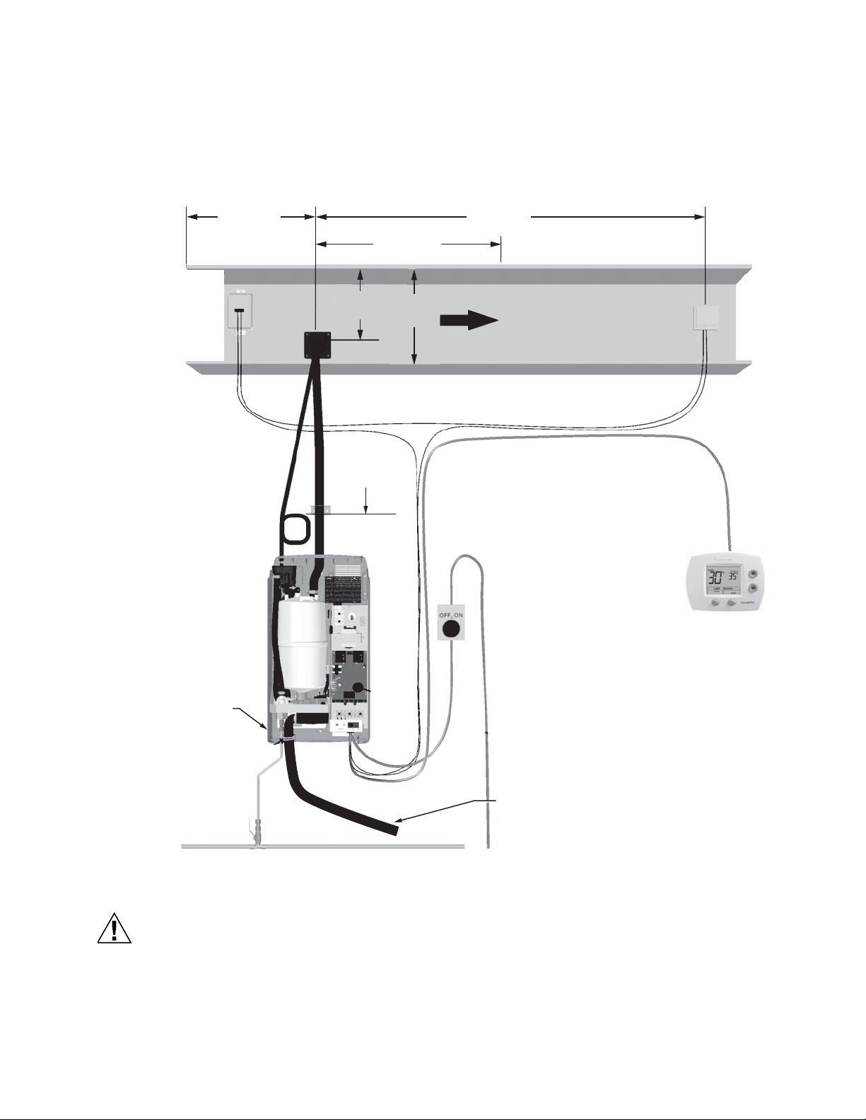
HM700A1000
MISE EN GARDE
CONDUITE 1/2 PO (MINIMUM) À 4 PI (1,2 M) MAXIMUM. 30-100 PSIG
AIR GAP
PURGEUR P
AVEC DISTANCE
VERTICALE MINIMUM
DE 12 PO (30 CM)
COURBURE OU AUTRE
OBSTRUCTION
ÉTIQUETTE DE
SPÉCIFICATIONS
VÉRIFICATION D'AIR
(EN OPTION)
EN SÉRIE ENTRE
LES BORNES 1 ET 2.
LE CAVALIER SITUÉ
ENTRE LES BORNES
1 ET 8 DOIT ÊTRE
RETIRÉ.
2 X HAUTEUR
DE CONDUIT
DEPUIS LE
VENTILATEUR
OU LA TRANSITION
10 PI (3 M) MIN.
4 PI (1,2 M) MIN.
8 PO
(20 CM)
MIN.
MF35807
2/3 DE LA
HAUTEUR
DU CONDUIT
ÉTIQUETTE DE
SPÉCIFICATIONS
DÉCONNEXION À FUSIBLE
TENSION, AMPÉRAGE ET PHASE CORRECTS
CONFORMES À L'ÉTIQUETTE DES
SPÉCIFICATIONS (EN OPTION)
MONTAGE
- UNITÉ À NIVEAU
- VISSÉE DANS LE
MEMBRE DE LA
CHARPENTE
RÉGULATEUR D’HUMIDITÉ
DANS LE CONDUIT DE RETOUR OU
À L'EMPLACEMENT REPRÉSENTANT
L'ESPACE HUMIDIFIÉ (PAS DE
COURANTS D'AIR ET ÉLOIGNÉE
DES PORTES ET DU DIFFUSEUR)
ONDUITE DE VAPEUR
PENTE ADÉQUATE
AUCUNE RESTRICTION
PAS DE PLIURES DANS LE TUYAU
PURGEURS DE CONDENSAT
SUR LES GRANDES LONGUEURS
REMARQU E : BORNES U OU HUM EN SÉRIE ENTRE LES BORNES 1 ET 2
HAUTE LIMITE
MARCHE/ARRÊT
(EN OPTION)
EN SÉRIE ENTRE
LES BORNES 1 ET 2.
LE CAVALIER SITUÉ ENTRE LES
BORNES 1 ET 8 DOIT ÊTRE RETIRÉ.
POUR PERMETTRE L'EAU DE CIRCULER LIBREMENT, S’ASSURER
QUE LA CONDUITE DE VIDANGE AIT UNE PENTE SUFFISANTE,
N’EMPRISONNE PAS L’EAU, ET NE FASSE PAS DE NŒUDS.
DÉMARRAGE
Vérification de l'installation
Avant de mettre l'humidificateur HM700 sous tension, inspectez l'installation pour vous assurer qu'elle est bien réalisée.
Risque de dégât matériel
Ne laissez pas le commutateur marche/arrêt/vidange
en position de vidange pendant plus d'un cycle de
vidange complet. Le solénoïde de la vanne de vidange
peut chauffer et causer des dommages à la vanne et
au câblage. Ne tentez pas de procéder à une vidange
lorsqu'il n'y a pas d'eau dans le système.
Fig. 19. Vérification de l'installation.
Marche/arrêt
L'humidificateur HM700 est configuré en usine pour
fonctionner comme un humidificateur marche/arrêt. Il est en
marche lorsque 24 V c.a. provenant de la borne 1 est transmis
à la borne 2 par un humidistat marche/arrêt ou d'autres
dispositifs de sécurité en série.
13 33-00118EFS—01
Page 38

HM700A1000
AVERTISSEMENT
Procédure de démarrage
1. Examinez l'humidificateur et l'installation pour détecter
tout dommage ou installation incorrecte.
2. Assurez-vous que la bouteille est bien installée dans la
vanne de vidange et que les connecteurs de l'électrode
sont entièrement enfoncés dans les broches de la
bouteille.
3. Assurez-vous que le couvercle avant est installé et
attaché avec ses vis de fixation.
4. Ouvrez le robinet de coupure d'eau.
5. Établissez l'alimentation principale en utilisant le
sectionneur installé.
Risque de blessures.
Les unités endommagées ou mal installées ne doivent
pas être utilisées. Les unités endommagées ou mal
installées peuvent constituer un danger pour les
personnes et les biens.
6. Mettez l'interrupteur marche/arrêt à l'avant de
l'humidificateur sur marche.
• L'humidificateur effectue une séquence
d'autodiagnostic durant laquelle les voyants et les
composants internes s'activent momentanément.
Voir « Voyants d'état » à la page 15 pour obtenir
des informations sur les voyants et les séquences.
• Si une erreur est détectée durant la séquence
d'autodiagnostic, l'humidificateur ne se met pas en
marche. Le voyant d'état jaune clignote en
séquence pour indiquer qu'une erreur a été
détectée. Voir les Tableaux 7 et 8 pour obtenir des
informations sur le diagnostic et la correction des
erreurs.
• Après le test du système, l'humidificateur est en
mode de fonctionnement normal.
7. Contrôlez et ajustez le point de consigne du régulateur
et l'humidistat haute limite.
8. Lorsque l'humidistat externe génère une demande
d'humidité et que la boucle de sécurité est fermée, le
voyant vert d'humidification à l'avant de l'humidificateur
s'allume, le relais d'alimentation sur le tableau de
commande s'active, la vanne de remplissage est
actionnée (après un délai) et la bouteille se remplit
lentement d'eau.
REMARQUE : Lorsque la bouteille se remplit d'eau, aucun
écoulement d'eau dans le drain ne doit se
produire. Si de l'eau s'écoule dans le drain,
cela peut indiquer une contre-pression
excessive ou une fuite de la vanne de
vidange. Voir la section Dépannage.
9. Si un relais d'activation de ventilateur est utilisé, le
voyant vert continue de clignoter jusqu'à ce que le
dispositif de vérification de présence d'air se ferme. Une
fois fermé, le voyant vert s'allume en continu et
l'humidificateur commence à produire de la vapeur, tel
que décrit à l'étape 8.
10. Cinq à dix minutes peuvent être nécessaires pour que
les électrodes immergées chauffent l'eau et pour
produire de la vapeur.
REMARQUE : Si de l'eau à faible conductivité est utilisée,
plusieurs heures peuvent être requises
pour que l'humidificateur HM700 atteigne
sa capacité de production maximum. Ceci
est normal. Pendant ce temps,
l'humidificateur ne procède à aucune
vidange et la conductivité de l'eau dans la
bouteille augmente. Pour accélérer ce
processus, ajoutez 1/4 de cuillère à thé de
sel dans la bouteille. Ceci augmente
immédiatement la conductivité de l'eau et
initie le réchauffement.
33-00118EFS—01 14
Page 39

FONCTIONNEMENT
MF35828
STATUS
DRAIN OFF ON
JAUNEVERT
HM700A1000
Voyants d'état
L'interface utilisateur HM700 comprend 2 voyants qui
fournissent des informations sur l'état de l'humidificateur.
Fig. 20. Voyants d'état.
Les voyants jaune et vert clignotent
Indique qu'il n'y a aucune demande d'humidité.
Le voyant jaune clignote
Panne détectée, l'humidificateur a cessé de fonctionner.
Comptez le nombre de clignotements et consultez le
Tableau 8 pour plus d'informations.
Le voyant vert clignote
Indique que l'humidificateur est alimenté mais qu'il n'y a
pas de demande d'humidité. La boucle de sécurité (1-2)
est ouverte.
Le voyant jaune est allumé
Indique que le niveau d'eau est élevé.
Lorsque le voyant jaune est allumé en continu (non
clignotant), il indique que le capteur de niveau d'eau
élevé a interrompu le remplissage de la bouteille. Le
voyant est uniquement destiné à signaler le problème,
et à moins qu'il ne reste allumé pendant une période de
temps prolongée, aucune action n'est requise.
Le voyant vert est allumé
Indique que de la vapeur est produite.
Sélection d'un point de consigne d'humidité relative
Le point de consigne d'humidité optimal dépend des raisons
pour lesquelles un espace est humidifié. Les
recommandations des « Applications de CVCA du guide de
l'ASHRAE » fournissent les humidités relatives pour
différentes applications spécifiques.
Santé et confort – Une plage d'humidité de 40 à 60 % est
particulièrement bénéfique pour la santé et le confort. Un
réglage d'humidité de 45 à 50 % est recommandé à ces fins
pour éviter une humidité excessive.
Réduction de la température – Par climat froid, il est souvent
nécessaire de réduire le niveau d'humidité dans un
environnement climatisé pour empêcher l'accumulation de
condensation à l'intérieur des murs extérieurs, des fenêtres et
des boiseries. Il est vivement recommandé d'utiliser la
fonction de réduction de l'humidité sur le régulateur
HumidiPRO dans ces conditions pour éviter les dommages
causés par la condensation. Le régulateur numérique avec
capteur de température extérieure installé réduira
automatiquement le point de consigne d'humidité en fonction
de la température extérieure.
15 33-00118EFS—01
Page 40
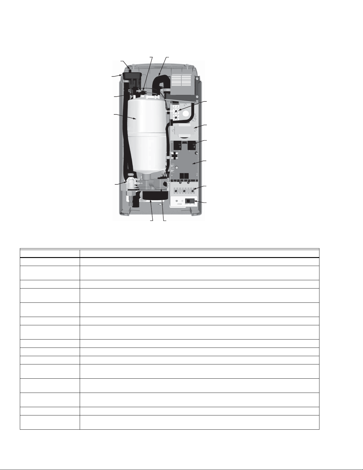
HM700A1000
RETOUR DE
CONDENSAT
CUVETTE DE
REMPLISSAGE
BOUCHON DE
BOUTEILLE
BOUTEILLE
VANNE DE
REMPLISSAGE
CONNECTEUR DE
CAPTEUR DE NIVEAU
D'EAU ÉLEVÉ
SORTIE DE
VAPEUR
VANNE DE VIDANGECANAL DE VIDANGE
BORNIER
HAUTE TENSION
TRANSFORMATEUR
RELAIS D'ALIMENTATION
TABLEAU DE
COMMANDE
BARRETTE DE
BORNES DE
COMMANDE
COMMUTATEUR
MARCHE/ARRÊT/VIDANGE
MF35827
Fig. 21. Composants de l'humidificateur.
Composant Fonction
Retour de condensat Fournit une connexion pour retourner le condensat vers l'humidificateur.
Barrette de bornes de
commande
Barrette de bornes pour la connexion des régulateurs externes à l'humidificateur et l'interface vers
d'autres équipements.
Bouchon de bouteille Connecteurs d'alimentation vers électrodes dans la bouteille.
Bouteille Maintient les électrodes dans l'eau. Le courant entre les électrodes génère la chaleur utilisée pour
chauffer la vapeur.
Canal de vidange Combine l'eau de vidange de la bouteille et l'excédent de la cuvette de remplissage en une sortie de
vidange unique.
Vanne de vidange Vide l'eau de l'humidificateur.
Tableau de commande Contrôle toutes les fonctions de l'humidificateur et fournit des connexions d'entrée et de sortie aux
composants de l'humidificateur.
Cuvette de remplissage Fournit un intervalle d'air pour empêcher le débit de retour.
Vanne de remplissage Contrôle le débit d'eau dans l'humidificateur.
Bornier haute tension Connexion d'alimentation principale du sectionneur à distance à l'humidificateur.
Connecteur de capteur
Utilisée pour détecter le niveau d'eau maximum dans la bouteille.
de niveau d'eau élevé
Commutateur
marche/arrêt/vidange
Active et désactive le contrôleur de l'humidificateur et vide la bouteille. Remarque : Désactivez le
sectionneur de l'humidificateur pour couper l'alimentation principale vers l'humidificateur.
Relais d'alimentation Établit/coupe l'alimentation vers les électrodes de bouteille sur signal du contrôleur de l'humidificateur
(monté sur le tableau de commande).
Sortie de vapeur Connectez à la conduite de vapeur avec le tuyau de vapeur.
Transformateur Réduit la tension principale à 24 V c.a. pour le contrôleur et les composants internes tels que la
vanne de remplissage et la vanne de vidange.
33-00118EFS—01 16
Page 41

ENTRETIEN ET MAINTENANCE
MISE EN GARDE
MF35704
POINT DE MONTAGE INTERNE
DES ÉLECTRODES.
LA BROCHE DU CAPTEUR DE NIVEAU
D'EAU ÉLEVÉ EST MUNIE D'UN COLLIER
EN PLASTIQUE SUR SON POURTOUR.
CONNECTEZ LE FIL DU CAPTEUR
DE NIVEAU D'EAU ÉLEVÉ
ORANGE ICI.
SORTIE DE VAPEUR
FIXEZ LE TUYAU DE VAPEUR À LA
SORTIE AVEC LA BRIDE DE TUYAU.
BROCHE D'ÉLECTRODE
CONNECTEZ LES BOUCHONS À CODE COULEUR
DE LA BOUTEILLE À LA BROCHE AVEC ÉTIQUETTE
DE COULEUR CORRESPONDANTE. LE BOUCHON
À RESSORT DOIT BIEN S'ENCASTRER SUR LA
BROCHE. REMPLACEZ EN CAS DE DESSERRAGE
OU DE DOMMAGE.
ÉTIQUETTE
IDENTIFIE LES INFORMATIONS DE LA
BOUTEILLE COMPREND AUSSI LES
INFORMATIONS SUR LA SÉCURITÉ ET LES
COORDONNÉES.
Maintenance requise
L'humidificateur HM700 a été conçu pour nécessiter un
entretien minime. L'entretien régulier consiste à vérifier que
l'humidificateur est en bon état, à remplacer la bouteille
lorsque le logiciel l'indique et à nettoyer la vanne de vidange
lorsque la bouteille est remplacée.
ERREUR DE FIN DE VIE DE BOUTEILLE
Lorsque la bouteille atteint sa fin de vie, l'humidificateur
HM700 arrête de fonctionner et le voyant jaune clignote en
séquences de 4 clignotements. Voir le Tableau 8 à la page
page 23 pour plus d'informations sur les autres séquences de
clignotement. La bouteille doit être remplacée.
La bouteille de vapeur est jetable et doit être jetée en fin de
vie. La durée de vie de la bouteille dépend des conditions de
l'eau et de l'utilisation de l'humidificateur.
HM700A1000
Si la bouteille n'est pas remplacée en fin de vie,
son fonctionnement sera compromis et
l'humidificateur pourrait être endommagé.
Honeywell n'est pas responsable des dommages
causés ou attribués au non-remplacement d'une
bouteille usagée (voir la garantie du fabricant).
REMARQUE : Honeywell recommande d'avoir une
bouteille de rechange en stock durant toute
la saison d'humidification. Ceci permet
d'éliminer les temps d'arrêt lorsque
l'humidificateur indique que la bouteille est
en fin de vie.
BOUTEILLE DE RECHANGE
L'étiquette sur la bouteille existante identifie le type de
bouteille en haut à gauche. Lors de la commande d'une
bouteille, indiquez toujours le numéro de modèle à trois ou
cinq chiffres indiqué sur l'étiquette, ainsi que le numéro de
série et la tension de l'humidificateur. Le numéro de série et la
tension sont situés sur l'étiquette des spécifications sur la
gauche de l'humidificateur.
Fig. 22. Bouteille HM700 (HM700ACYL2).
17 33-00118EFS—01
Page 42

HM700A1000
AVERTISSEMENT
V
Retrait de la bouteille
Débranchez l'alimentation principale au niveau du
sectionneur externe avant tout entretien.
L'intérieur de l'armoire de l'humidificateur contient des
éléments haute tension et le câblage. L'accès doit être
réservé au personnel autorisé.
1. Videz la bouteille en mettant le commutateur
marche/arrêt/vidange en position de vidange. Laissez
l'humidificateur se vider jusqu'à l'eau arrête de s'écouler
du drain (généralement pas plus de 10 minutes).
2. Mettez le commutateur marche/arrêt/vidange sur arrêt.
3. Fermez le robinet de coupure d'eau.
LE BOUCHON DE LA
BOUTEILLE SE TIRE
ERTICALEMENT.
4. Mettez l'humidificateur hors tension à l'aide du
sectionneur externe.
5. Retirez les deux vis fixant le couvercle avant.
6. Retirez les bouchons de la bouteille des broches de la
bouteille en tirant verticalement.
7. À l'aide d'un tournevis plat, desserrez la bride du tuyau
à l'endroit où le tuyau est connecté à la bouteille.
8. Inclinez le haut de la bouteille pour la dégager du tuyau
de vapeur. Lorsque la bouteille est dégagée du tuyau de
vapeur, sortez-la.
REMARQUE : L'humidificateur HM700 a une bride de
fixation réutilisable pour sécuriser la
bouteille lors du transport ainsi que pour
l'installation à domicile. Elle doit être
desserrée ou retirée pour retirer la
bouteille. Serrez-la lorsque la bouteille
neuve est installée.
COLLIER DE SERRAGE
DU TUYAU
VIS DE COUVERCLE
BOUTEILLE
INCLINEZ LA BOUTEILLE
VERS L'AVANT POUR
DÉGAGER LE TUYAU
PUIS TIREZ-LA DE LA
VANNE DE VIDANGE.
INCLINEZ LE
COUVERCLE VERS
L'AVANT POUR
COMMUTATEUR MARCHE/ARRÊT/VIDANGE
LE RETIRER.
MF35705
Fig. 23. Retrait de la bouteille.
33-00118EFS—01 18
Page 43

Nettoyage de la vanne de vidange
MISE EN GARDE
ORIFICE DE BOUTEILLE ET
JOINT TORIQUE
FIL DE TERRE
SOLÉNOÏDE
CONNECTEURS À
COSSE OUVERTE
ÉCROU EN LAITON
(ACTIONNEUR)
VIS
TUYAU ET
BRIDE DE TUYAU
MF35700
MF35707
MANCHON
ET SOLÉNOÏDE
RESSORT
(NOTEZ L'ORIENTATION)
PISTON
ACTIONNEUR
Nettoyez toujours la vanne de vidange avant d'installer une
bouteille neuve. Le tartre provenant de la bouteille usagée
peut être tombé dans la vanne de vidange, ce qui
compromettrait son fonctionnement. Pour bien nettoyer la
vanne de vidange, elle doit être enlevée et démontée.
1. Débranchez les cosses ouvertes de la vanne de
vidange.
2. Retirez les deux vis fixant la vanne au bac de vidange.
3. Serrez les languettes de la bride à ressort maintenant le
tuyau à la vanne de vidange et faites glisser la bride
vers le haut du tuyau. Tirez le tuyau de la vanne de
vidange. Soulevez la vanne de vidange du bac de
vidange.
4. Détachez le capuchon rouge du solénoïde et retirez le
solénoïde de la vanne.
5. Desserrez l'écrou en laiton maintenant l'actionneur sur
le boîtier plastique avec une clé et démontez
l'actionneur.
6. Nettoyez les composants de l'actionneur et le boîtier de
la vanne (ports d'entrée et de sortie et orifice de
bouteille). Placez le joint torique neuf fourni avec la
bouteille neuve dans la vanne.
7. Remontez l'actionneur en veillant à ce que l'extrémité
conique du ressort soit orientée comme illustré sur la
Fig. 25. Serrez l'écrou en laiton à la main puis de 1/4 de
tour supplémentaire.
8. Nettoyez l'extrémité du tuyau et réinstallez-le sur la
vanne. Faites glisser la bride du tuyau en place et
placez la vanne dans le bac de vidange.
9. Fixez la vanne sur le bac de vidange avec deux vis.
Fig. 24. Vanne de vidange.
HM700A1000
Fig. 25. Actionneur de vanne de vidange.
Installation de la bouteille neuve
Assurez-vous que le modèle de la bouteille neuve
est HM700ACYL2. L'utilisation de tout autre
modèle ou d'une bouteille réusinée annulera la
garantie de l'humidificateur HM700.
1. Insérez la bouteille dans la vanne de vidange. Inclinez
la bouteille vers l'avant et insérez le tuyau de vapeur
dans la sortie de vapeur. Inclinez la bouteille en arrière
pour la remettre en place.
2. Serrez la bride du tuyau en veillant à ne pas trop serrer
et à ne pas écraser la sortie de vapeur en plastique de
la bouteille.
3. Attachez les bouchons à code couleur de la bouteille
sur la broche de couleur correspondante de la bouteille.
Enfoncez bien. Connectez le connecteur du capteur de
niveau d'eau élevé. Les bouchons à ressort doivent bien
s'encastrer sur la broche de la bouteille. Remplacez-les
s'ils sont lâches ou endommagés.
4. Rattachez la bride de fixation.
5. Replacez le couvercle de l'humidificateur et fixez-le
avec deux vis.
6. Mettez l'humidificateur sous tension à l'aide du
sectionneur externe.
7. Ouvrez le robinet de coupure d'eau.
8. Mettez le commutateur marche/arrêt/vidange sur
marche.
19 33-00118EFS—01
Page 44

HM700A1000
Arrêt prolongé
S'il s'avère nécessaire de débrancher l'alimentation vers
l'humidificateur pour une période prolongée, videz toujours la
bouteille avant.
1. Mettez le commutateur marche/arrêt/vidange sur
vidange.
2. Patientez jusqu'à ce que l'humidificateur soit
complètement vidé (prend généralement moins de 10
minutes).
3. Mettez le commutateur marche/arrêt/vidange sur
vidange.
4. Mettez l'humidificateur hors tension à l'aide du
sectionneur externe.
5. Fermez le robinet de coupure d'eau.
REMARQUE : Tant que l'humidificateur HM700 est
alimenté, il vide automatiquement la
bouteille lorsqu'il n'y a pas eu de demande
d'humidité pour une période de temps
prolongée. Cette fonctionnalité permet de
réduire ou d'éviter la corrosion des
électrodes et l'accumulation d'algues et de
bactéries dans la bouteille. La bouteille
reste vide jusqu'à ce qu'une demande
d'humidité ait lieu, causant l'ouverture de la
vanne et le remplissage de la bouteille.
L'appareil suit le processus normal pour un
fonctionnement optimal.
DÉMARRAGE APRÈS ARRÊT PROLONGÉ
1. Vérifiez que l'humidificateur n'a pas été endommagé et
que l'installation n'a pas été modifiée. Voir « Procédure
de démarrage typique » à la page 14.
2. Mettez l'humidificateur hors tension à l'aide du
sectionneur externe.
3. Mettez le commutateur marche/arrêt/vidange sur
vidange.
4. Patientez jusqu'à ce que l'eau ne s'écoule plus dans le
drain. Ceci prend généralement moins de 10 minutes.
5. Suivez la procédure de démarrage typique indiquée à la
page 14.
33-00118EFS—01 20
Page 45

DÉPANNAGE
MISE EN GARDE
MISE EN GARDE
Danger - Haute tension.
Soyez conscient, lors du dépannage, que
l'humidificateur est sous haute tension, et qu'il est
important de posséder de bonnes connaissances en
matière de bonnes pratiques et de câblage. Tout
dépannage nécessitant l'ouverture de l'armoire doit
être réalisé par un personnel qualifié.
Risque de brûlure et d’ébouillantement.
Une température de l’eau ou de la vapeur supérieure
à 49 °C (120 °F) peut causer des brûlures par
ébouillantement.
REMARQUE : La plupart des défaillances de
l'humidificateur ne sont pas causées par un
équipement défaillant mais par une
installation incorrecte. Un diagnostic
complet des défaillances implique toujours
un examen approfondi de l'ensemble du
système. Souvent, la connexion du tuyau
HM700A1000
de vapeur n'a pas été correctement
réalisée, ou la faute incombe au système de
régulation de l'humidité.
EXIGENCES EN MATIÈRE DE DÉPANNAGE
• Assurez-vous que l'installation répond aux exigences
d'installation décrites dans le chapitre Installation de ce
manuel.
• Familiarisez-vous avec le fonctionnement de
l'humidificateur en lisant le chapitre Fonctionnement de ce
manuel.
• Le schéma de câblage spécifique de votre humidificateur
est installé à l'intérieur de la porte de l'humidificateur. Une
copie générique du schéma de câblage de l'humidificateur
HM700 est également inclus à la fin de ce chapitre à titre
de référence.
• Lorsque vous communiquez avec votre représentant local
ou le représentant Honeywell pour obtenir de l'aide pour le
dépannage, veuillez disposer du numéro de série pour
référence.
La section suivante fournit des directives générales pour le
dépannage de l'humidificateur HM700 et des composants
auxiliaires. Pour obtenir des informations de dépannage
détaillées, reportez-vous aux manuels fournis avec
l'équipement auxiliaire et au Tableau 8 intitulé « Dépannage
des erreurs de l'humidificateur HM700 » à la page 23.
Tableau 7. Dépannage général.
Symptôme Cause Action(s) corrective(s)
Rien ne se passe
lorsque commutateur
marche/arrêt est
actionné.
Fusible grillé Vérifiez le fusible en ligne entre le transformateur et le tableau
de commande.
Tension incorrecte Vérifiez que la tension est conforme à l'étiquette des
spécifications et corrigez-la si nécessaire.
Le transformateur abaisseur ne produit
pas 24 V c.a.
Cavalier d'alimentation principale
incorrect
Remplacez le transformateur.
Vérifiez que le cavalier sur le bornier haute tension est
connecté entre P et la borne correspondant à la tension
d'alimentation. Voir la Fig. 16.
21 33-00118EFS—01
Page 46

HM700A1000
Tableau 7. Dépannage général. (suite)
Symptôme Cause Action(s) corrective(s)
L'humidificateur
n'humidifie pas ou
n'atteint pas son point
de consigne
Boucle de sécurité ouverte Vérifiez qu'il y a 24 V c.a. à la borne 2.
Vérifiez le câblage et le fonctionnement des dispositifs
marche/arrêt connectés aux bornes 1 et 2.
Vérifiez qu'un cavalier est installé dans la boucle de sécurité
du dispositif de vérification de présence d'air, bornes 1 et 8.
Pas de signal de demande Vérifiez la tension entre les bornes 3 et 4. Pour la
configuration de la demande, 35 % du signal à pleine échelle
doit être présent pour que l'humidificateur se mette en
marche.
La capacité a été manuellement limitée Contrôlez le potentiomètre de réglage de la capacité
manuelle. Le sens horaire augmente la capacité.
Faible conductivité de l'eau Notez si le voyant jaune est allumé. Si de l'eau à faible
conductivité est utilisée, plusieurs heures peuvent être
requises pour que l'humidificateur HM700 atteigne sa
capacité de production maximum. Ceci est normal. Pendant
ce temps, l'humidificateur ne procède à aucune vidange et la
conductivité de l'eau dans la bouteille augmente. La
conductivité peut être augmentée plus rapidement en ajoutant
1/4 de cuillère à thé de sel.
Aucune circulation d’air dans le conduit Vérifiez que les bornes d'activation du ventilateur de
l'humidificateur (bornes 19-20) sont correctement câblées à la
chaudière. Vérifiez que le dispositif de vérification de présence
d'air est câblé à la borne 8.
L'humidificateur a
rencontré une erreur et
Le logiciel a détecté une condition
anormale
Voir le Tableau 8 à la page 23.
le voyant jaune clignote
Le distributeur crache
de l'eau
Le distributeur n'est pas à niveau Utilisez le support à l'extrémité du distributeur pour vous
assurer qu'il est à niveau.
Le purgeur P est trop près du
distributeur
Le purgeur P doit être à 12 po (30 cm) au-dessous du
distributeur pour garantir le débit. Modifiez son emplacement
si nécessaire.
La conduite de condensat n'est pas
suffisamment inclinée
Une pente suffisante pour garantir le débit est requise.
Réinstallez-le si nécessaire.
Purgeur bloqué Vérifiez que de l'eau s'écoule par le purgeur. Dégagez
l'obstruction le cas échéant.
Conduite de vapeur non isolée Si la conduite de vapeur est longue, l'accumulation de
condensat peut surcharger le port de condensat du
distributeur. Isolez la conduite pour améliorer l'efficacité et
installez des purgeurs de condensat supplémentaire si
nécessaire.
Installation incorrecte de la conduite de
vapeur
Vérifiez que la conduite de vapeur a été installée avec des
purgeurs de condensat et qu'elle est inclinée. Voir «
Instructions relatives aux conduites de vapeur et au retour de
condensat » à la page 8.
Condensation dans le
conduit
Les dégagements requis pour
l'installation n'ont pas été respectés
Les exigences de conception ont
changé
Consultez le manuel d'installation du distributeur pour les
dégagements requis. Relocalisez le distributeur si nécessaire.
Contrôlez la température et l'humidité de l'air d'arrivée pour
déterminer si les conditions ont changé.
La limite haute ne fonctionne pas Contrôlez le réglage et le fonctionnement de la limite haute.
Remplacez-la si elle est défectueuse.
L'humidificateur
déclenche le
disjoncteur de fuite à la
terre.
L'humidificateur est câblé à un circuit
muni d'un disjoncteur de fuite à la terre.
Le fil de terre de la vanne de vidange
n'est pas débranché
Consultez les étapes de l'installation électrique et les
remarques à la page 10 pour les instructions relatives au
disjoncteur de fuite à la terre et au retrait du fil de terre.
33-00118EFS—01 22
Page 47

HM700A1000
Erreur de l'humidificateur HM700
Le système d'autodiagnostic intégré dans l'humidificateur
HM700 surveille continuellement le fonctionnement de
l'humidificateur. Lorsqu'une condition anormale ne pouvant
pas être corrigée par le logiciel se produit, l'humidificateur
HM700 coupe l'alimentation vers la bouteille et la vide, et
signale l'erreur à l'aide du voyant jaune.
Effacement d'une erreur
• Contrôlez la séquence de clignotement en utilisant la liste
des messages d'erreur, et prenez toutes les actions
correctives pour corriger la ou les causes, tel que décrit
dans le Tableau 8 à la page 23.
• Mettez l'humidificateur hors tension et sous tension à l'aide
de l'interrupteur marche/arrêt en attendant 10 secondes
avant de le remettre en marche.
Séquence de clignotement du voyant
Pour signaler la différence entre les erreurs, le voyant jaune
clignote selon différentes séquences. Le Tableau 8 indique les
séquences d'erreur pouvant s'afficher, leur signification, la
cause possible et les actions correctives suggérées.
Tableau 8. Dépannage des erreurs de l'humidificateur HM700.
Voya nt
jaune Symptôme Cause Action(s) corrective(s)
1
clignotement
2
clignotements
Courant excessif
Le courant a
dépassé 130 % du
maximum
Pas de courant
La vanne de
remplissage est
activée depuis
longtemps mais le
niveau d'eau élevé
n'est pas atteint.
Le remplissage doit
avoir lieu à plus de 1
po par minute.
Drain obstrué, concentration d'eau
excessive
Solénoïde de vidange non activé,
concentration d'eau excessive
Remplissage trop rapide, vanne de
remplissage endommagée ou
présentant une fuite
Remplissage trop rapide, vanne de
remplissage incorrecte
Eau fournie trop conductrice a) Modifiez l'approvisionnement en eau
Cycle court de l'humidificateur a) Vérifiez que le cycle marche/arrêt de la limite haute
Bouteille incorrecte installée Installez une bouteille de modèle correct
Bouteille usagée mais non détectée
par le logiciel
Condensat d'une autre source Retirez les retours de condensat ailleurs que sur la
Contre-pression Éliminez la contre-pression
Fuite de la vanne de vidange ou
vanne de vidange coincée en position
ouverte
Robinet de coupure d'eau fermé Ouvrez le robinet de coupure d'eau
Filtre de la vanne de remplissage
obstrué
Contre-pression élevée du système a) Vérifiez que le tuyau n'est pas plié
Capteur de niveau d'eau élevé non
connecté
Faible conductivité de l'eau a) Vérifiez que de l'eau potable est fournie et non pas
Nettoyez la conduite de vidange
Contrôlez et corrigez le câblage vers la vanne de
vidange.
Remplacez la vanne de remplissage
La vanne de remplissage est peut-être défectueuse.
Remplacez-la si nécessaire
b) Contactez le représentant de Honeywell pour
obtenir de l'aide
ou des autres commandes marche/arrêt se produit en
moins de cinq minutes. Contrôlez l'emplacement et le
réglage de la limite haute.
b) Réduisez la sortie en diminuant le potentiomètre
Remplacez la bouteille (consultez le chapitre sur
l'entretien)
conduite de vapeur.
Nettoyez ou remplacez la vanne de vidange (consultez
le chapitre sur l'entretien)
Nettoyez le filtre sur l'entrée de la vanne de
remplissage.
b) Vérifiez que le condensat est bien retiré (consultez
le chapitre sur l'installation).
Vérifiez que le bouchon de bouteille marqué en blanc
est connecté à l'électrode courte avec un puits en
plastique sur son pourtour et au tableau de
commande.
de l'eau traitée (à osmose inverse ou déionisée).
b) Vérifiez la conductivité de l'eau. Si elle est inférieure
à 150 μS, ajoutez 1/4 de cuillère à thé de sel dans la
cuvette de remplissage et relancez l'unité.
23 33-00118EFS—01
Page 48

HM700A1000
Tableau 8. Dépannage des erreurs de l'humidificateur HM700. (suite)
Voya nt
jaune Symptôme Cause Action(s) corrective(s)
3
clignotements
Pas de courant,
niveau d'eau élevé
L'eau a atteint le
haut de la bouteille
sans courant
Le fil principal n'est pas bouclé dans
le transformateur de courant.
Le connecteur du capteur de niveau
d'eau élevée est sur une broche
d'électrode.
Les bouchons de la bouteille sont mal
installés
Recâblez le fil principal par le transformateur de
courant.
Installez le connecteur du capteur de niveau d'eau
élevée sur la broche de la bouteille enveloppée.
Vérifiez que les couleurs des bouchons de bouteille
correspondent aux repères près des électrodes sur la
bouteille et que le bouchon de bouteille marqué en
blanc est connecté à l'électrode courte située dans le
puits en plastique.
4
clignotements
Bouteille usagée
Les électrodes sont
couvertes de tartre.
Les électrodes de bouteille sont
couvertes de tartre et l'humidificateur
ne peut pas répondre à la demande
Remplacez la bouteille par le même numéro de
modèle (consultez le chapitre sur l'entretien).
33-00118EFS—01 24
Page 49
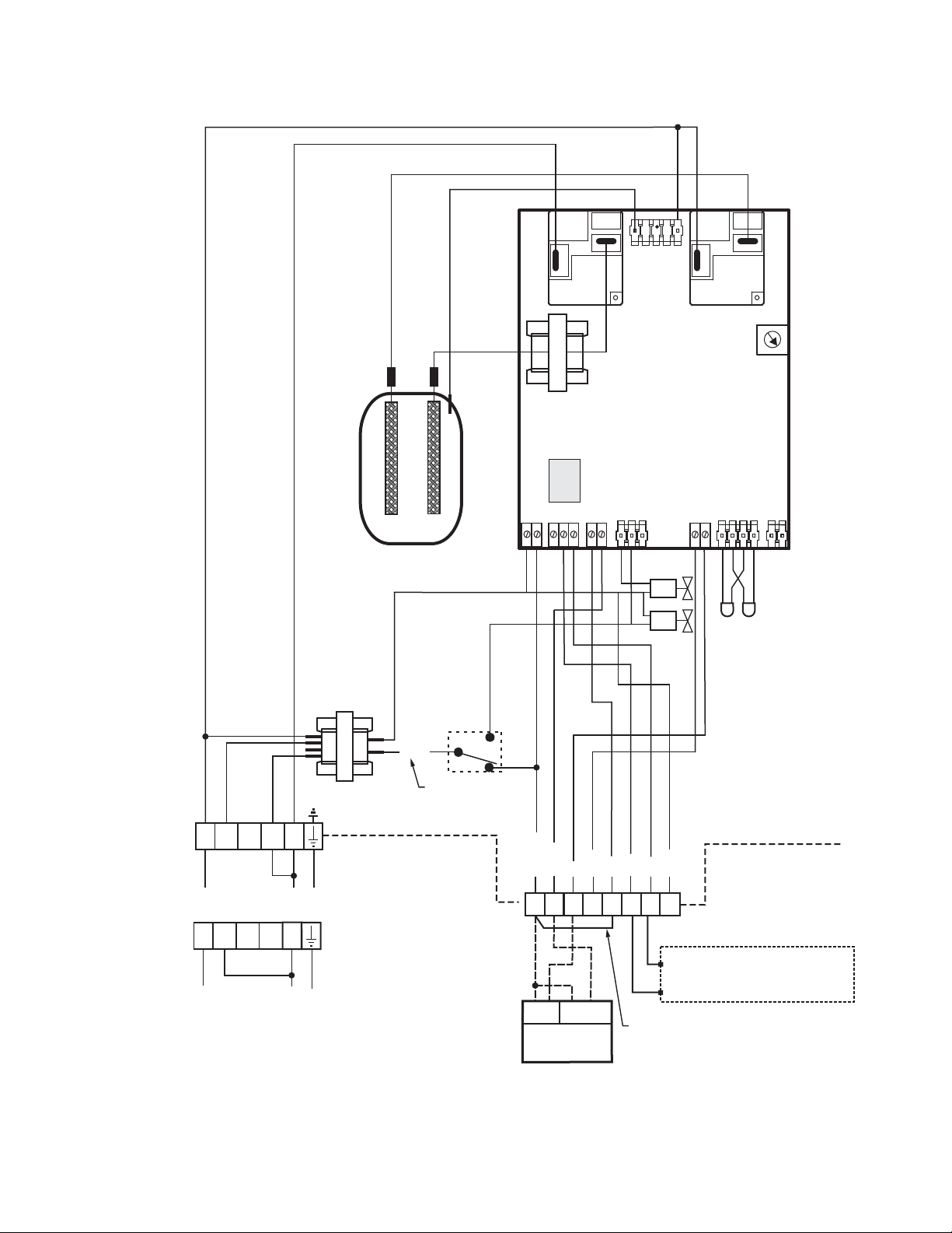
K2
P8
NIVEAU D'EAU
ÉLEVÉ
HM700A1000
K3
POTENTIOMÈTRE
BOUTEILLE
COMMUTATEUR
MARCHE/ARRÊT/
VIDANGE
240/208/
120 V c.a.
TRANSFORMATEUR
240 V c.a.
SOUS
120 V c.a.
SOUS
REMARQUE : INSTALLEZ LE CAVALIER DEPUIS LA BORNE DE LA PDF
CORRESPONDANT À LA TENSION SECTEUR.
120L1
TENSION
120L1
TENSION
N/A
N/A
240 P
240 P
MASSE
SOUS TENSION
MASSE
NEUTRE
S
24 V c.a.
1,5 A
INTERNE
EXTERNE
P1 P2 P3 P4 P5 P6 P7
VANNE
REMPLISSAGE
G
Y
VOYANTS
VANNE VIDANGE
D'ÉTAT
HUM
R / HUM
C
1
2
3
DEMANDE
24V
HUM.
RÉGULATEUR
D’HUMIDITÉ
N/A
AP
4
8
19
N/A
GF
RF
20
21
REMARQUE :
POINTS SECS POUR ACTIVATION
DU VENTILATEUR DE CHAUDIÈRE.
CONTRÔLEUR PILOTE 24 V UNIQUEMENT
BORNE INSTALLÉE EN USINE
MF35721
Fig. 26. Schéma de câblage.
25 33-00118EFS—01
Page 50

HM700A1000
GARANTIE DE 5 ANS
Honeywell garantit ce produit contre tout vice de fabrication ou de matériau dans la mesure où il en est fait une utilisation et un
entretien convenables, et ce, pour cinq (5) ans à partir de la date d’achat par le consommateur. En cas de défaillance ou de
mauvais fonctionnement pendant la période de garantie, Honeywell remplacera ou réparera le produit (à sa discrétion).
Si le produit est défectueux,
(i) le renvoyer avec la facture ou une autre preuve d’achat date au lieu d’achat; ou
(ii) appeler le service à la clientèle de Honeywell en composant le 1-800-468-1502. Le service à la clientèle déterminera si le
produit doit être retourné à l’adresse suivante :
Honeywell Return Goods, Dock 4MN10-3860, 1985 Douglas Dr. N., Golden Valley, MN 55422, ou si un produit de remplacement
peut vous être expédié.
La présente garantie ne couvre pas les frais de retrait ou de réinstallation. La présente garantie ne s’appliquera pas s’il est
démontré par Honeywell que la défaillance est due à un endommagement du produit qui s'est produit lorsque le consommateur
l’avait en sa possession.
La responsabilité exclusive de Honeywell se limite à réparer ou à remplacer le produit conformément aux modalités
susmentionnées. HONEYWELL N’EST EN AUCUN CAS RESPONSABLE DES PERTES OU DOMMAGES, Y COMPRIS LES
DOMMAGES INDIRECTS OU ACCESSOIRES DÉCOULANT DIRECTEMENT OU INDIRECTEMENT D’UNE VIOLATION
QUELCONQUE D’UNE GARANTIE, EXPRESSE OU TACITE, APPLICABLE AU PRÉSENT PRODUIT, OU TOUTE AUTRE
DÉFAILLANCE DU PRÉSENT PRODUIT. Certaines provinces ne permettent pas l'exclusion ou la restriction des dommages
indirects ou accessoires et, par conséquent, la présente restriction peut ne pas s'appliquer à votre cas.
CETTE GARANTIE EST LA SEULE GARANTIE EXPRESSE FAITE PAR HONEYWELL POUR CE PRODUIT. LA DURÉE DE
TOUTE GARANTIE IMPLICITE, INCLUANT LES GARANTIES DE QUALITÉ MARCHANDE OU D’ADAPTATION À UNE
UTILISATION PARTICULIÈRE, EST LIMITÉE PAR LES PRÉSENTES À LA PÉRIODE DE CINQ ANS DE LA PRÉSENTE
GARANTIE.
Certaines provinces ne permettent pas de limiter la durée des garanties tacites et, par conséquent, la présente limitation peut ne
pas s’appliquer. La présente garantie donne au consommateur des droits spécifiques et certains autres droits qui peuvent varier
d’une province à l’autre.
Pour toute question concernant la présente garantie, prière d’écrire aux Services à la clientèle de Honeywell à l’adresse
suivante : Honeywell Customer Relations, 1985 Douglas Dr, Golden Valley, MN 55422, ou de composer le 1-800-468-1502.
IMPORTANT
Pour conserver la garantie, utilisez uniquement des pièces et des bouteilles approuvées par Honeywell.
Solutions de régulation et d’automatisation
Honeywell International Inc.
1985 Douglas Drive North
Golden Valley, MN 55422
customer.honeywell.com
® Marque de commerce déposée aux États-Unis
© 2016 Honeywell International Inc.
33-00118EFS—01 M.S. 03-16
Imprimé aux États-Unis
Page 51

HM700A1000
HUMIDIFICADOR ELECTRODE STEAM
INSTRUCCIONES PARA LA INSTALACIÓN
Herramientas necesarias
— Destornillador
— Llave inglesa
— Pinzas
— Válvula de cierre de agua
— Línea de agua (de polietileno de baja densidad o de
cobre)
Configuración del humidificador
El HM700 viene configurado de fábrica para funcionar en la
mayoría de las condiciones sin la necesidad de cambiar los
parámetros.
NOTA: Como el humidificador viene configurado de
fábrica para funcionar de manera óptima,
Honeywell no recomienda cambiar los puentes
de conexión o el potenciómetro, ya que esto
anularía la garantía y podría dañar el
humidificador. Para obtener más información,
INTRODUCCIÓN
El HM700 es el humidificador de vapor doméstico más
avanzado del mercado, y brinda humidificación confiable y
continua para el hogar. El humidificador está diseñado para
conectarse a un distribuidor de vapor instalado en un
conducto de suministro de aire y satisfacer la demanda de
humedad.
IMPORTANTE
Lea y guarde estas instrucciones. Esta guía debe ser
conservada por el instalador, mientras que la Guía
para el usuario debe permanecer en poder del
propietario del equipo.
Artículos incluidos en la caja
— Humidificador de vapor (HM700)
— Kit de distribución con montaje a distancia
(HM700ADISTKIT)
— Higrostato HumidiPRO (H6062A1000)
— Cilindro de vapor (se incluye un HM700ACYL2)
— Manguera de desagüe de goma
— Instrucciones de instalación, Guía para el usuario y
Guía de inicio rápido
Antes de la instalación
póngase en contacto con el Servicio de atención
al cliente de Honeywell.
1. Asegúrese de que la tensión y la fase disponibles
coincidan con la tensión y la fase del humidificador;
estas aparecen indicadas en la etiqueta de
especificaciones del humidificador.
2. Asegúrese de que el interruptor de desconexión externo
con fusibles especializado presente el tamaño
adecuado para poder soportar el amperaje indicado en
la etiqueta de especificaciones. Consulte los códigos
locales.
3. Asegúrese de contar con suficiente espacio, tal como
se describe en la sección Ubicación en la página 6.
4. Asegúrese de que las líneas de vapor puedan
encaminarse hacia el conducto distribuidor, tal como se
describe en la sección Instrucciones de retorno del
condensado y líneas de vapor en la página 9.
Page 52
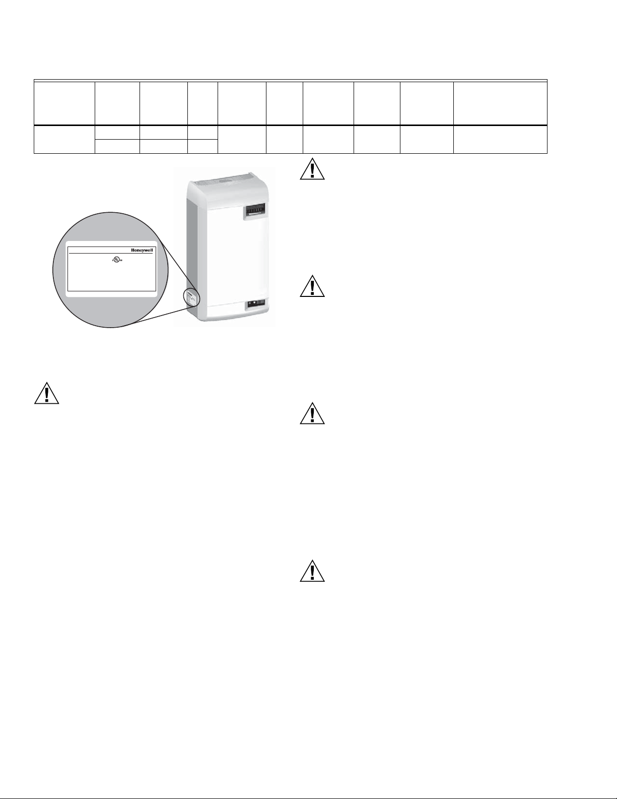
HM700A1000
PRECAUCIÓN
PRECAUCIÓN
PRECAUCIÓN
PRECAUCIÓN
PRECAUCIÓN
M35758
Golden Valley Minnesota 55422
MADE IN CANADA
MODEL:
VOLTS 1:
KW:
HM700A1000
S/N:
XXXXXXX
110-120
PHASE:
1
HZ:
60
1.4
DATE:
XXXXXXXXX
2583297A
220-240
VOLTS 2:
F.L.A: GPD:
12.0
F.L.A: GPD:
12.0
2.9
KW:
Auto-Adaptive
11
22
1
LISTED 205X
HUMIDIFIER
Tabla 1. Especificaciones.
Salida de
Número de
pieza Voltios
HM700A1000
110/120 11 1.4
220/240 22 2.8
vapor
(GPD) KW Amperios Fase
12.0 1 15 A CYL2
Fig. 1. Ubicación de la etiqueta de especificaciones.
Potencia
máxima
del fusible
externo
Cilindro
estándar
Peso
total/neto
en lb (kg)
15/20
(7.0/9.5)
Dimensiones en
pulgadas (L x W x H)
11.5 x 6.75 x 21.5
Eléctrico
Todos los trabajos de electricidad deben realizarse
conforme a los códigos eléctricos locales y
nacionales.
Las conexiones eléctricas deberán ser realizadas por
un electricista profesional.
Las unidades deben ser alimentadas por un circuito
de interruptor diferencial (ID) especializado.
Plomería
Los trabajos de plomería deberán ser realizados por
un plomero profesional.
El agua de desagüe que sale del humidificador puede
estar muy caliente. No vierta el agua por un
fregadero público.
Todos los trabajos de plomería deben realizarse
conforme a los códigos de plomería locales y
nacionales.
Mantenimiento
Antes de realizar cualquier tarea de mantenimiento,
desconecte la fuente de alimentación principal.
Tanto los compartimientos eléctricos como los
compartimientos de las tuberías contienen cables y
componentes de alta tensión. El acceso debe
limitarse solo al personal autorizado.
Durante y después del funcionamiento del
humidificador, tanto el vapor como los componentes
en contacto con el vapor, como las líneas de vapor,
los distribuidores de vapor y las líneas de
condensado, pueden calentarse y provocar
quemaduras al contacto.
Honeywell no acepta ninguna responsabilidad por las
instalaciones del equipo de humidificación
realizadas por personal no calificado ni por el uso
de piezas, componentes o equipos no autorizado o
aprobados por Honeywell.
Para mantener la garantía, solo deben utilizarse
piezas y cilindros aprobados por Honeywell en el
producto.
Instalación
No coloque la unidad sobre superficies calientes.
No coloque la unidad en un área donde pueda ocurrir
congelamiento.
No coloque la unidad sobre superficies que vibren.
No coloque la unidad en el piso.
El HM700 produce vapor a presión atmosférica. No
conecte dispositivos que puedan bloquear la salida
de vapor al extremo de salida de vapor.
Las líneas de vapor deben instalarse de modo que
ninguna obstrucción pueda generar una
contrapresión en el humidificador.
Calidad del agua
El HM700 de Honeywell requiere una conexión de
agua fría desde el suministro principal de agua de
su hogar, de entre 30 y 100 PSIG. Es posible que
se necesite una válvula de estrangulación; por
razones de seguridad, se recomienda utilizar una
válvula de cierre de agua. No se debe utilizar agua
depurada por ósmosis inversa (OI) ni agua
desionizada (DI). La conductividad del agua es
importante para garantizar que el humidificador por
electrodos funcione de manera eficaz. Honeywell
recomienda un conductividad de 150 a 1200 μS
(microsiemens).
33-00118EFS—01 2
Page 53

HM700A1000
Piezas y accesorios
Se encuentran disponibles las siguientes piezas y accesorios; además, es posible que vengan incluidos con su humidificador
HM700. El cilindro es el único artículo que deberá reemplazar periódicamente, a fin de mantener el funcionamiento correcto del
humidificador.
Tabla 2. Piezas y accesorios.
Pieza/accesorio Número de pieza
Cilindro de reemplazo HM700ACYL2
Higrostato HumidiPRO H6062A1000
Kit de distribución de acero inoxidable, con montaje a distancia HM700ADISTKIT
Válvula de desagüe de reemplazo HM700ADVALVE
Válvula de llenado de reemplazo HM700AFVALVE
Transformador de reemplazo HM700ATX
Tablero de control de parámetros (PC) de reemplazo HM700APCB
Kit de manguera aislada para la línea de condensado y la línea de vapor de 15 ft (4.5 m) HM700AHOSEKIT
Interruptor de presión diferencial para la prueba de aire 50027910-001
3 33-00118EFS—01
Page 54

HM700A1000
Cómo trabaja el humidificador
El HM700 es un generador de vapor atmosférico que utiliza el
calor generado por la corriente eléctrica que fluye entre los
electrodos sumergidos para generar vapor. El HM700 está
diseñado para satisfacer una de demanda de humidificación
del aire a través de un distribuidor de vapor.
incrustaciones, el humidificador no podrá alcanzar su
plena capacidad. El software del HM700 supervisa esta
condición; cuando la detecte, el humidificador dejará de
funcionar y se encenderá una luz LED amarilla en una
secuencia repetitiva de 4 parpadeos.
GENERACIÓN DE VAPOR
• Luego de que la unidad recibe una señal de demanda y se
cierra el bucle de seguridad entre los terminales 1 y 2, el
humidificador cierra el contactor y mide la corriente
eléctrica.
• Si la demanda es menor que la producción real, la válvula
de entrada se mantiene cerrada y la salida se reduce
mediante la disminución por evaporación del nivel de agua
en el cilindro.
• Si la demanda es mayor que la producción real, la válvula
de llenado se activa luego de una breve demora y el agua
fluye hacia el recipiente de llenado. El agua fluye desde el
recipiente de llenado hacia la parte inferior del cilindro por
una manguera conectada a la cubierta de la válvula de
desagüe.
NOTA: El cilindro es alimentado por gravedad desde el
recipiente de llenado. Si la contrapresión de la
línea de vapor es demasiado alta, provocará que
el agua regrese desde el recipiente de llenado y
fluya por la línea de rebose hacia el desagüe.
• Cuando el agua en el cilindro entra en contacto con los
electrodos energizados, la corriente fluye por el agua. La
resistencia del agua a la carga eléctrica genera calor y, a
su vez, vapor. La corriente eléctrica (y la generación de
vapor) aumenta a medida que se incrementa el nivel de
agua, puesto que una mayor parte del electrodo se
encuentra sumergido. La unidad continúa llenándose
hasta que la corriente se corresponde con la demanda, o
bien el sensor de exceso de agua detecta un nivel de agua
alto.
• El HM700 repite el ciclo de llenado y evaporación varias
veces hasta que la generación de vapor se corresponde
con la demanda.
• Con el tiempo, los minerales presentes en el agua se
adherirán a los electrodos del cilindro. El humidificador se
llenará automáticamente con un nivel superior de agua, a
fin de mantener la capacidad completa durante la vida útil
del cilindro. Eventualmente, debido a la formación de
DESAGÜES
• Mientras se genera vapor, los minerales son excluidos, lo
que aumenta la conductividad del agua. El ciclo
autoadaptable patentado del HM700 monitorizará la
conductividad del agua y efectuará desagües para
mantener la conductividad óptima del agua y garantizar el
máximo rendimiento.
• El ciclo autoadaptable asegura que se maximice la vida útil
del cilindro. Para ello, proporciona un control estricto y un
uso óptimo del agua durante toda la vida útil del cilindro.
DISTRIBUCIÓN DE VAPOR
Es posible introducir el vapor generado por el humidificador
en el aire de diferentes maneras. El método más común para
añadir el vapor en el aire es mediante la instalación de un
tubo distribuidor de vapor en un conducto de suministro de
aire.
LÍNEA DE VAPOR
La línea de vapor que se extiende desde la salida de vapor
del cilindro y el distribuidor cumple dos funciones: se utiliza
como un conducto de transferencia del vapor atmosférico
desde el humidificador hacia el distribuidor, y como un medio
para eliminar el condensado. Para obtener información sobre
la selección de líneas de vapor, consulte la sección
“Instrucciones de retorno del condensado y líneas de vapor”
en la página 9.
RETORNO DEL CONDENSADO
Cada vez que se distribuye vapor, se forma condensado en el
sistema de distribución. Aislar las líneas de vapor es una
manera de reducir la cantidad de condensado generado. Las
líneas de vapor se encuentran inclinadas, a fin de que el
condensado no permanezca en las líneas y obstruya el flujo
de vapor. Es importante recolectar y eliminar el condensado
del sistema, a fin de que no se acumule ni se filtre en el
conducto. El condensado puede ser devuelto al recipiente de
llenado del HM700 para reducir el desperdicio de agua, o bien
puede verterse en el desagüe.
33-00118EFS—01 4
Page 55
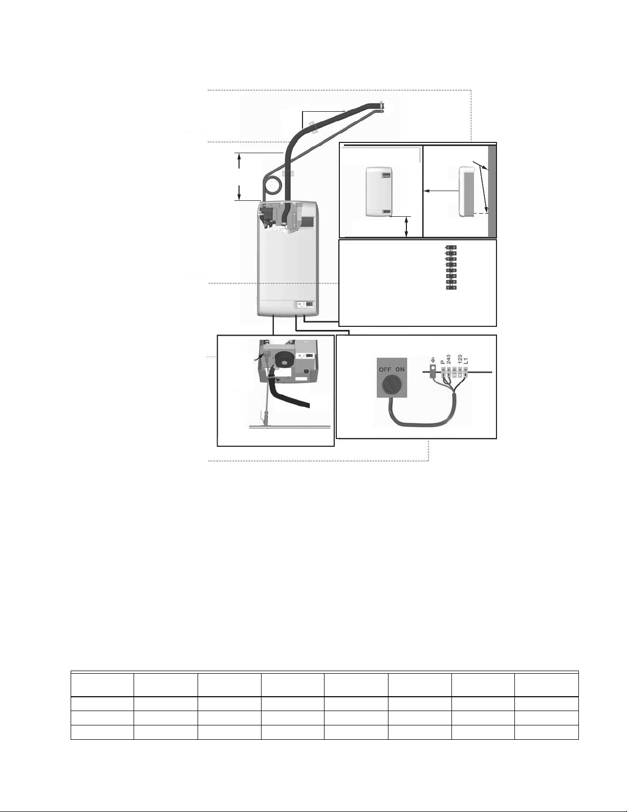
MONTAJE
DISTRIBUCIÓN
DE VAPOR
CONTROLES
12 (305)
COMO MÍN.
2 (51)
COMO MÍN.
12 (305)
24 (610)
ALTURA MÍN.
TORNILLOS DE 2 (51)
36 (914)
COMO MÍN.
1 - R/HUM
2 - HUM
3 - C
4 - NC
8 - AP
19 - Gf
20 - Rf
21 - NC
HM700A1000
PLOMERÍA
ELÉCTRICO
CALIBRACIÓN
IMPORTANTE
El HM700 debe instalarse únicamente después de
haberse calibrado adecuadamente. No use pies
cuadrados para calibrar la instalación de un
humidificador. En cambio, se deben utilizar pies
cúbicos, puesto que la humedad llena un volumen
de espacio (ancho x largo x alto). Además, tenga en
cuenta la “hermeticidad” de la construcción de un
hogar.
LÍNEA DE AGUA
DE PEBD DE
1/8 NPT O CON
UNA JUNTA DE
COMPRESIÓN DE 1/4
AGUA POTABLE FRÍA, DE 30 A 100 PSIG,
1/2 IN COMO MÍN.
INTERRUPTOR
DE CIRCUITO O
INTERRUPTOR
DE
DESCONEXIÓN
ESPECIALIZADOS
Fig. 2. Instalación típica de un HM700.
Dimensiones en pulgadas (mm).
El HM700 produce 11 galones por día (GPD) cuando funciona
a 120 V, y produce 22 GPD cuando funciona a 240 V. Para
obtener detalles sobre la configuración del HM700 para que
funcione con una tensión diferente, consulte la Figura 16.
La Tabla 3 incluye las recomendaciones del Instituto de Aire
Acondicionado, Calefacción y Refrigeración (AHRI) con
respecto a los requisitos de humedad; la Tabla 4 incluye los
humidificadores y las configuraciones de producción que
cumplirán con los requisitos de humidificación.
(OPCIONAL)
ON
OFF
NOTA: CONEXIÓN DE 240 V
CONEXIÓN
A TIERRA
HM700
EXTERNA
MS35805
Tabla 3. Humedad recomendada por el AHRI (en galones por día).
Tipo de
construcción 8,000 ft
3
12,000 ft
3
16,000 ft
3
20,000 ft
3
24,000 ft
3
28,000 ft
3
32,000 ft
Hermética 3.3 4.3 5.4 7.5 9.6 11.7 16
Promedio 7.6 9.6 11.8 16 20.3 24.4 33
No hermética 11.7 14.9 18.1 24.5 30.8 37.1 50
5 33-00118EFS—01
3
Page 56
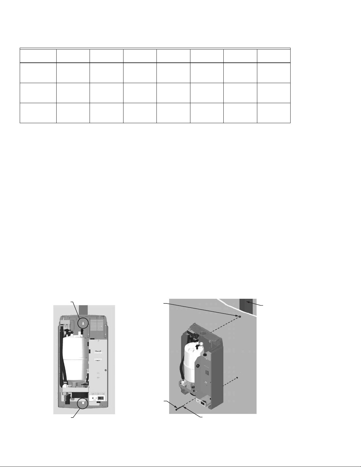
HM700A1000
LUEGO DE COLGAR
EL HUMIDIFICADOR,
INSTALAR EL
SEGUNDO TORNILLO
8 TORNILLOS PARA
MADERA DE 2 IN (5 CM)
INSERTAR EL TORNILLO
HASTA QUE SOBRESALGA
SOLO ¼ IN (6 MM)
COLGAR LA UNIDAD;
LUEGO, AJUSTAR
EL TORNILLO
PERNOS 2X4 U
OTRA PIEZA
ESTRUCTURAL
BOCALLAVE
MS35759
ORIFICIO
Tabla 4. Humidificador(es) de vapor necesario(s) para la aplicación.
Tipo de
construcción 8,000 ft
3
12,000 ft316,000 ft
3
20,000 ft
3
24,000 ft
3
28,000 ft
11 GPD (x2)
Hermética 11 GPD 11 GPD 11 GPD 11 GPD 11 GPD
22 GPD (x1)
11 GPD (x3)
Promedio 11 GPD 11 GPD 22 GPD 22 GPD 22 GPD
22 GPD (x2)
11 GPD (x3)
No hermética 22 GPD 22 GPD 22 GPD
o
22 GPD (x2)
a
En la tabla presentada anteriormente, 11 GPD se refiere a un humidificador de vapor configurado para funcionar a 120 V, mien-
11 GPD (x3)
o
22 GPD (x2)
11 GPD (x4)
22 GPD (x2)
a
3
32,000 ft
3
11 GPD (x2)
o
o
22 GPD (x1)
11 GPD (x3)
o
o
22 GPD (x2)
11 GPD (x5)
o
o
22 GPD (x3)
tras que 22 GPD se refiere a un humidificador de vapor configurado para funcionar a 240 V.
UBICACIÓN
Monte el equipo en una pared o una superficie vertical apta. No
coloque la unidad en el piso. Deje los espacios requeridos para
NOTA: No coloque la unidad sobre superficies
calientes, en áreas donde pueda ocurrir
congelamiento, sobre superficies que vibran ni
en el suelo.
realizar las conexiones eléctricas y de tuberías. Las
dimensiones de los espacios mostradas son solo de referencia;
representan las separaciones mínimas requeridas para poder
realizar el mantenimiento del humidificador. Antes de la
ubicación e instalación final de la unidad consulte los códigos
locales y nacionales. Honeywell no se hace responsable por
los incumplimientos a los códigos de instalación.
• Instale la unidad únicamente en áreas con una
temperatura ambiente de 41 a 104 °F (de 5 a 40 °C) y una
humedad relativa de 5 a 95 %.
• Cuando sea posible, instálela debajo del distribuidor de
vapor. Asegúrese de encaminar la línea de vapor
adecuadamente y proporcionar los sifones de condensado
correctos.
• NO ubique el humidificador más lejos de lo absolutamente
necesario del distribuidor de vapor, puesto que la
producción neta se reducirá como resultado de la pérdida
de calor a lo largo de la línea de vapor.
Montaje con bocallaves
1. El humidificador HM700 se monta en la pared a través
de una bocallave ubicada en la parte posterior de la
ebanistería de la unidad.
2. Use 8 tornillos de 2 in (5 cm) montados en pernos 2x4 o
más largos. Se necesitan 2 tornillos, uno para colgar la
unidad y otro para asegurarla, de modo que no se
despegue de la bocallave.
3. Coloque el tornillo superior hasta que sobresalgan solo
¼ in (6 mm). Eleve la unidad y coloque la cabeza del
tornillo en la bocallave.
4. Asegúrese de que la unidad se encuentre nivelada;
luego, inserte y ajuste el segundo tornillo por el orificio
inferior. Ajuste el tornillo superior. Consulte la Fig. 3.
NOTA: Si observa cartón yeso u otro espaciador, use
tornillos más largos.
• Cuando sea posible, instale el humidificador HM700 a una
altura conveniente para realizar el mantenimiento.
Fig. 3. Montaje con bocallave.
33-00118EFS—01 6
Page 57
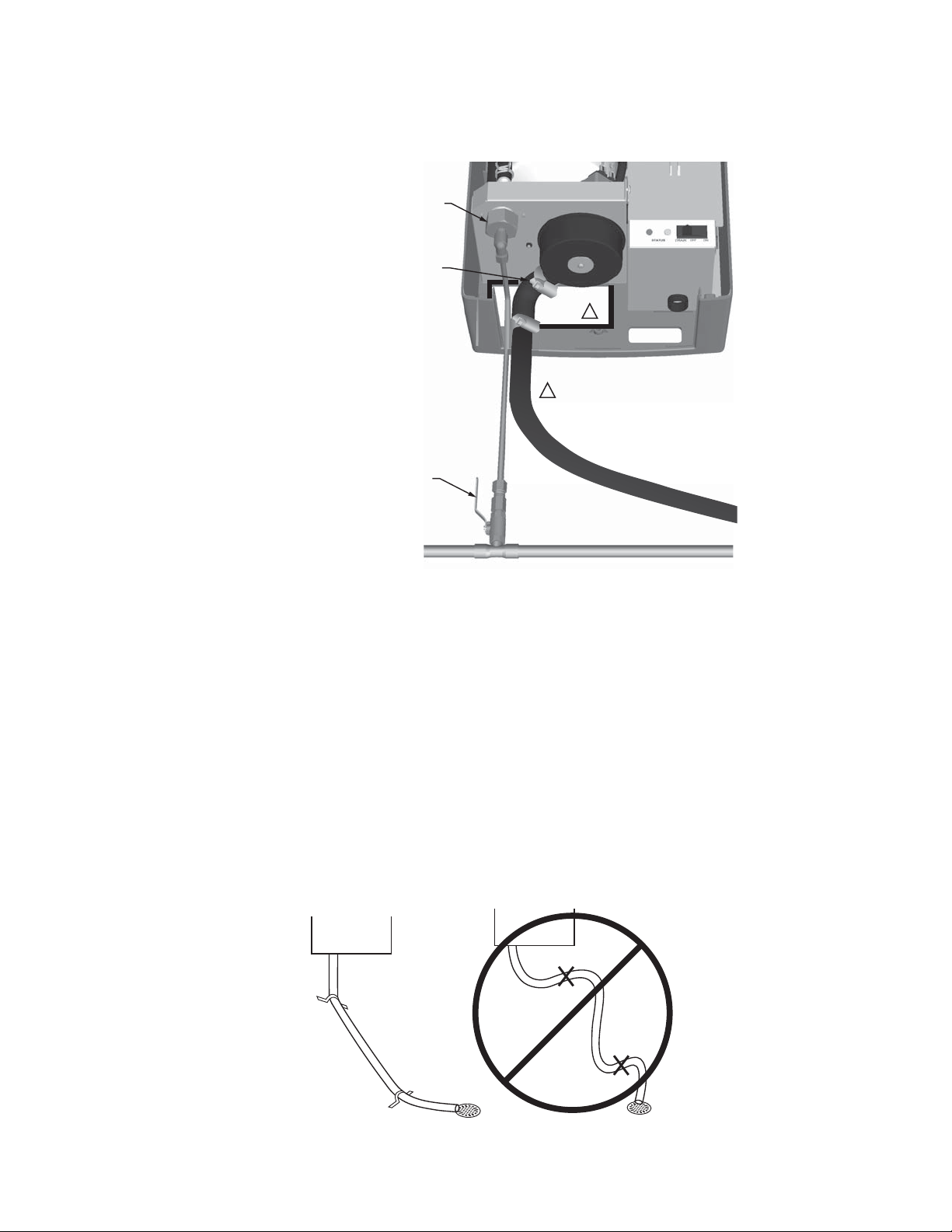
PLOMERÍA
DE 1/2 IN (30 MM)
SIEMPRE SE DEBE INSTALAR UNA
VÁLVULA DE CIERRE DE AGUA.
USAR UNA JUNTA DE COMPRESIÓN DE
1/4 IN (INCLUIDA) PARA CONECTAR LA
LÍNEA DE SUMINISTRO DE AGUA A
LA UNIDAD (DE PEBD O COBRE).
USAR LÍNEAS DE SUMINISTRO DE COBRE,
CON UN DE DE 1/2 IN, A UNA DISTANCIA MÁXIMA
DE 4 FT (1.2 M) CON RESPECTO AL HUMIDIFICADOR
MS35760
1
LAS LÍNEAS DE LLENADO Y DESAGÜE
TAMBIÉN PUEDEN ENCAMINARSE POR
LA APERTURA EN LA PARTE
POSTERIOR DEL GABINETE.
1
M35855
HM700A1000
IMPORTANTE
— Todas las conexiones de las líneas de desagüe y
— Cuando el HMW700 realiza un desagüe, el agua de
• El suministro de agua debe presentar una presión de 30 a
100 psig. En caso de ser necesario, se puede utilizar una
válvula de estrangulamiento.
• No utilice agua depurada por ósmosis inversa ni agua
desionizada. La conductividad óptima del agua de
suministro debe ser de entre 150 y 1200 μS
(microsiemens).
Fig. 4. Suministro de agua y conexiones de desagüe.
suministro deben instalarse conforme a los códigos
locales de plomería.
desagüe se refrigera automáticamente a 140 °F
(60 °C). Si se utiliza el interruptor de desagüe
manual, la temperatura puede ser superior. El
material de desagüe (tubo y desagüe) debe ser
capaz de soportar una temperatura de 200 °F
(93 °C).
• El agua de suministro debe estar fría, a una temperatura
de 34 a 68 °F (de 1 a 20 °C).
• Para facilitar el mantenimiento, instale la válvula de cierre
de agua antes que el humidificador.
• La línea de desagüe no debe finalizar en un fregadero
utilizado frecuentemente por el personal, o en un lugar
prohibido por los códigos de plomería. Por motivos de
seguridad, encamine la línea hacia un desagüe en el piso
o un área similar.
• La tubería de desagüe debe dirigirse de forma que permita
el flujo libre del agua. Conserve la pendiente adecuada, sin
retenedores y sin torceduras. Un desagüe obstruido puede
causar la acumulación del agua del cilindro y resultar en
una operación deficiente.
• Si no cuenta con un desagüe cerca del humidificador, use
una bomba de condensación que pueda ser utilizada con
agua de desagüe caliente.
Fig. 5.
7 33-00118EFS—01
Page 58

HM700A1000
W
2/3 W
1/3 W
MÍN. A = 8 (203)
H
1/3 W
1/3 W
1/3 W
MS35755
MS35756
1 VUELTA
1
2
3
+45˚
–45˚
MS35764
FLUJO DE AIRE
1/3
2/3
Distribuidor de vapor
El HM700 requiere la instalación de un distribuidor de vapor
en el extremo de entrada de los conductos. El HM700 puede
distribuir vapor a un conducto de ventilación a través del
distribuidor que se muestra en la Tabla 5.
Tabla 5. Distribuidor de vapor.
Número de pieza Descripción Notas
HM700ADISTKIT
Kit de montaje remoto de
distribución de acero inoxidable
Incluye un distribuidor de vapor, una manguera de vapor aislada de 5 ft,
una manguera de condensado y un equipo de instalación.
El distribuidor de vapor debe instalarse lo más cerca posible
del humidificador. Unas líneas de distribución de vapor cortas
minimizan la pérdida de condensación y la posibilidad de que
se genere una contrapresión en ellas.
Fig. 8. Distribuidor instalado horizontalmente
en un conducto horizontal.
FLUJO
DE AIRE
Fig. 6.
1/3
2/3
MS35765
Fig. 9. Distribuidor instalado horizontalmente
en un conducto vertical.
Gire el distribuidor 45° para que el vapor
se descargue hacia el centro del conducto,
en la dirección del flujo de aire.
FLUJO
DE AIRE
MS35766
33-00118EFS—01 8
Fig. 7.
Fig. 10. Distribuidor instalado verticalmente
en un conducto horizontal.
Esta configuración no se recomienda.
Page 59

HM700A1000
MS35761
ABRAZADERA DE RESORTE
TUBO DE COBRE CON UN DIÁMETRO EXTERNO DE 3/8”
ABRAZADERA
DE RESORTE
INSERTAR LA MANGUERA
SOBRE EL TUBO DE COBRE
Y FIJARLA CON LA
ABRAZADERA DE
RESORTE
Instrucciones de retorno del condensado y líneas de vapor
Para instalar las líneas de vapor del HM700, se deben seguir las siguientes instrucciones. El hecho de no utilizar el material
recomendado o superar el largo máximo recomendado en la Tabla 6, así como de no seguir las instrucciones de instalación de
las líneas de vapor, resultará en un funcionamiento deficiente y podría anular la garantía.
Tabla 6. Material recomendado para las líneas de vapor del HM700.
Longitud
máxima de
Producción de
vapor Material
Tubo de
Manguera
Voltaje
110/120V 3.85 (1.75)
220/240V 7.7 (3.5) 12 (3.5) 1.5 (0.7) 230
de vapor
7/8 in. 3/4 in.
MED-L
cobre
*
Tubo de
acero
inoxidable ft (m) lb/h (kg/h)
0.875 x
0.049 A
* El uso de líneas de vapor que no sean de tubería de cobre, de acero inoxidable o provistas por Honeywell anulará la garantía y
puede afectar el funcionamiento del humidificador de manera negativa.
* Si se utilizan tuberías de cobre o acero inoxidable (que no sean las tuberías suministradas), se recomienda aislarlas debido a
motivos de seguridad relacionados con las altas temperaturas y a fin de reducir el condensado.
Para devolver el condensado al HM700, inserte un tubo de cobre (que se suministró con el equipo) hasta la mitad de la apertura
de condensado del recipiente de llenado, junto con la abrazadera de resorte (que se suministró con el equipo).
la línea de
vapor Pérdidas potenciales
Flujo de
mínimo
7 (2) 0.5 (0.2) 115
aire
(cfm)
Presión
estática
máximalb/h (kg/h)
3.0 in. w.c.
Inserte la manguera de condensado en el orificio de retorno del condensado, que se encuentra en la parte superior del HM700,
y sobre el tubo de cobre. Fíjela con la abrazadera de resorte.
REGLAS FUNDAMENTALES PARA LAS LÍNEAS DE VAPOR ATMOSFÉRICO
• Las líneas de vapor no deben presentar obstrucciones que puedan generar una contrapresión.
• Tenga en cuenta los materiales, las dimensiones y las longitudes recomendadas; consulte las tablas.
• Instale una línea de vapor de forma vertical (hacia arriba) desde el HM700 a la boquilla de distribución. Consulte las
• Aíslela con material aislante de tuberías de 1.0 in (2.5 cm).
• Instale un sifón de condensado (utilice una “T” de tamaño completo para los sifones).
• No ajuste la abrazadera de la manguera en demasía en la salida de vapor del cilindro. El par de torsión máximo es de 12 in/lb.
• Apoye la línea de vapor para que el peso no recaiga sobre el cilindro.
• Los sifones de condensado deben ubicarse a una altura mínima de 6 in (15 cm) o a una presión estática de + 2 in (5 cm), lo
• Utilice sifones en forma de “P” o de terminación en espiral. Utilice todos los soportes necesarios para asegurar que la
Fig. 11. Retorno del condensado.
Figuras 12 a 14 para obtener información sobre otras opciones de instalación.
que sea mayor.
línea no se doble.
9 33-00118EFS—01
Page 60

HM700A1000
MS35717
CONECTA
LA MANGUERA
DE CONDENSADO
AL RECIPIENTE
DE LLENADO
RADIO MÍNIMO
DE 12 (305)
ANTES DE
CADA CURVA
RADIO MÍNIMO
DE 12 (305)
LÍNEA DE
CONDENSADO
SOPORTES
12 (305)
2 (51)
COMO
MÍNIMO
CONECTAR LA
MANGUERA DE
VAPOR AL CILINDRO
LÍNEA DE
CONDENSADO
12 (305)
COMO MÍNIMO
MS35718
SOPORTES
SIFÓN DE
CONDENSADO
AL DESAGÜE
RADIO
MÍNIMO DE
12 (305)
RADIO MÍNIMO
DE 12 (305)
ANTES DE
CADA CURVA
MS35719
AL DESAGÜE
OBSTRUCCIÓN
12 (305)
COMO MÍNIMO
RADIO
MÍNIMO
DE 12 (305)
RADIO MÍNIMO
DE 12 (305)
ANTES DE
CADA CURVA
SOPORTES
UTILIZAR UNA T DE TAMAÑO
COMPLETA EN UN PUNTO
INFERIOR INCLINAR LAS LÍNEAS
HASTA LA “T” E INMEDIATAMENTE
DESPUÉS DE ESTA
LA MANGUERA SE ABLANDARÁ CON EL TIEMPO. SE REQUIERE UN APOYO
ADECUADO.
1
AL DESAGÜE
2 (51)
COMO
MÍNIMO
12
(305)
COMO
MÍN.
1
Ejemplos de instalación de la línea de vapor
Fig. 12. Distribuidor de vapor sobre el humidificador
(manguera). Dimensiones en pulgadas (mm).
Fig. 13. Distribuidor de vapor debajo del humidificador
(manguera). Dimensiones en pulgadas (mm).
33-00118EFS—01 10
Fig. 14. Distribuido de vapor debajo del humidificador
con una obstrucción (manguera). Dimensiones en
pulgadas (mm).
EL SIFÓN DE
CONDENSADO NO SE
ENCUENTRA
12 (305) POR
DEBAJO DEL
DISTRIBUIDOR.
NO HAY UN SIFÓN
DE CONDENSADO
EN POSICIÓN VERTICAL.
LA LÍNEA DE VAPOR NO
SE ENCUENTRA INCLINADA.
MS35720
Fig. 15. Errores comunes durante la instalación de la línea
de vapor. Dimensiones en pulgadas (mm).
Page 61

ELECTRICIDAD
PRECAUCIÓN
PRECAUCIÓN
ADVERTENCIA
PRECAUCIÓN
240 V CA
L1
N/A
P
120 240
120 V CA
ACTIVO
ACTIVO
PUENTE
L1
N/A
P
120 240
ACTIVO
NEUTRO
TIERRA TIERRA
PUENTE
240 V CA
L1
N/AP120 240
120 V CA
ACTIVO
ACTIVO
ACTIVO
PUENTE
L1
N/A
P
120
240
NEUTRO
TIERRA
TIERRA
PUENTE
MS35850
Las conexiones eléctricas deberán ser realizadas
por un electricista profesional.
Esta unidad debe instalarse en un circuito de
interruptor diferencial (ID).
Riesgo de daño en el equipo
El hecho de no realizar el cableado del humidificador
conforme a las instrucciones de cableado puede
causar daños permanentes. Estos errores anularán la
garantía.
HM700A1000
El humidificador HM700A se debe instalar
utilizando un interruptor de circuito dedicado de
15 amp y cableado directamente para que cumpla
con el listado de productos de UL. Todo el
cableado se debe realizar de acuerdo con los
códigos eléctricos locales.
Los enchufes de cables eléctricos se pueden
recalentar y ocasionar riesgo de daños a la propiedad
y/o lesiones personales.
Nota: La garantía del producto se anulará si no se
cumplen estas instrucciones.
INSTALACIÓN DEL CABLE DE PUENTE
• NO instale el cable de voltaje de la red eléctrica (activo o neutro) en el terminal de 120 o 240.
• INSTALE los cables de la red eléctrica en el terminal L1 (activo) y en el terminal P (activo/neutro).
• INSTALE el puente de P al terminal de 120 o 240 (de acuerdo con el voltaje de la red eléctrica).
Pasos para la instalación
1. La unidad requiere un circuito especializado protegido por un interruptor diferencial (ID). Conecte el circuito a un interrup-
tor de desconexión que se encuentre cerca del dispositivo, a fin de brindar una protección contra descargas eléctricas
durante el mantenimiento.
2. Conecte el humidificador al interruptor de desconexión, tal como se indica a la derecha.
3. Instale el puente de conexión suministrado de fábrica entre el terminal P y el terminal que corresponde a la tensión de ali-
mentación.
4. Quite el cable verde que se encuentra conectado al cuerpo de la carcasa y a la válvula de desagüe (quite el bidón para
5. Sujete el cable a tierra lo más cerca posible de la válvula de desagüe y elimine el exceso.
permitir el acceso).
M35779
11 33-00118EFS—01
Page 62

HM700A1000
CALIENTE
CALIENTE
CONEXIÓN A TIERRA
P
240
120
L1
CONEXIÓN A TIERRA
E
X
T
I
N
T
240 V CA (1 FASE)
120 V CA (1 FASE)
NEUTRO
CALIENTE
P
240
120
L1
CONEXIÓN A TIERRA
NOTA: CONECTAR 120 V CA,
“CALIENTE”, A L1.
(OPCIONAL)
(OPCIONAL)
NOTA: LOS CABLES ELÉCTRICOS
TAMBIÉN PUEDEN ENCAMINARSE
POR LA APERTURA EN LA PARTE
POSTERIOR DEL GABINETE.
CONEXIÓN A TIERRA
MS35806
Fig. 16. Conexión eléctrica principal.
NOTAS:
— Honeywell requiere el uso de un circuito de interruptor diferencial (ID) en este dispositivo, a fin de proteger al usuario
de las descargas eléctricas.
— Luego de instalarlo correctamente, quite el cable verde de la válvula de desagüe. El cable verde viene preinstalado
de fábrica para proteger al usuario en caso de una instalación deficiente o cuando no es posible instalar un circuito
de interruptor diferencial. Consulte la Fig. 24 para ver la ubicación del cable verde en la válvula de desagüe.
— Asegúrese de contar con la alimentación adecuada que proporcione el amperaje completo para el humidificador, tal
como se indica en la etiqueta de especificaciones.
— No use un cable neutro como un cable a tierra; conecte una terminación especializada de tierra a tierra.
— Todo el cableado debe cumplir con los códigos eléctricos nacionales y locales.
33-00118EFS—01 12
Page 63

CONTROLES EXTERNOS
HM700A1000
Cableado de conexión entre el ventilador y el HumidiPRO
Cuando se distribuye vapor en un conducto, es posible que
haya una demanda de humedad si no existe un flujo de aire.
Se puede utilizar el HM700 con control de humedad
HumidiPRO u otro tipo de termostato (como el termostato
Prestige de VisionPRO
activación de un ventilador durante una demanda de
humedad. Si se utiliza otro termostato, consulte el manual de
dicho control para obtener las instrucciones sobre el cableado
necesario para activar el ventilador con un dispositivo de
humidificación encendido.
NOTA: El humidificador no comenzará a producir vapor
hasta que se cierre el bucle de seguridad del
ventilador.
HVAC
®
de Honeywell) para permitir la
R
C
U
U
GYWR C
S
S
SENSOR DE
EXTERIORES
PRUEBA DE AIRE O
PUENTE DE CONEXIÓN
R/HUM
HUM
C
NC
AP
G
F
R
F
NC
Esta información se aplica a todos los controles, ya sean
suministrados de fábrica o no. Para realizar el cableado,
utilice un cable sólido de 18 AWG como mínimo y manténgalo
lo más corto posible.
Control de humedad
• Se puede ubicar en un conducto de aire de retorno
(recomendado) o en la habitación humidificada.
• Evite colocarlo cerca de un difusor de descarga de aire
humidificado.
• Instálelo en un área representativa de la humedad de
la habitación (las corrientes, las puertas, la luz del sol o
los voladizos, como los estantes, pueden afectar la
lectura).
Sensor de temperatura exterior opcional (no se muestra; se
incluye con el HumidiPRO)
• Instálelo en un área representativa de la temperatura
del aire.
R
HVAC
C
U
U
S
GYWR C
S
SENSOR DE
EXTERIORES
PRUEBA DE AIRE O
PUENTE DE CONEXIÓN
RELÉ SPDT
COM
NC
NO
R/HUM
HUM
C
NC
AP
G
F
R
F
NC
GYWRRc
NOTA: EL RELÉ SPDT ES NECESARIO PARA EVITAR
LA ACTIVACIÓN DEL TERMINAL “Y” SI EL
GYWRRc
TERMOSTATO NO AÍSLA “Y” Y “G”.
TERMOSTATO
Fig. 17. Conecte el humidificador de vapor a un termostato
digital.
MS35754
TERMOSTATO
MS35730
Fig. 18. Conecte el humidificador de vapor a un
termostato mecánico.
NOTA: Si se utiliza un termostato Prestige, VisionPRO o Lyric (o similar) para controlar la humedad, conecte los dos contactos
HUM a los terminales 1 y 2 del HM700. Con el puente de conexión en su lugar, entre los terminales 1 y 8 en el HM700,
solo se necesitan estos dos cables para controlar la humedad. Asegúrese de configurar el control para forzar al
ventilador a que se active con una demanda de humedad, o durante un ciclo de calor si no se utiliza el cableado de
activación del ventilador.
13 33-00118EFS—01
Page 64
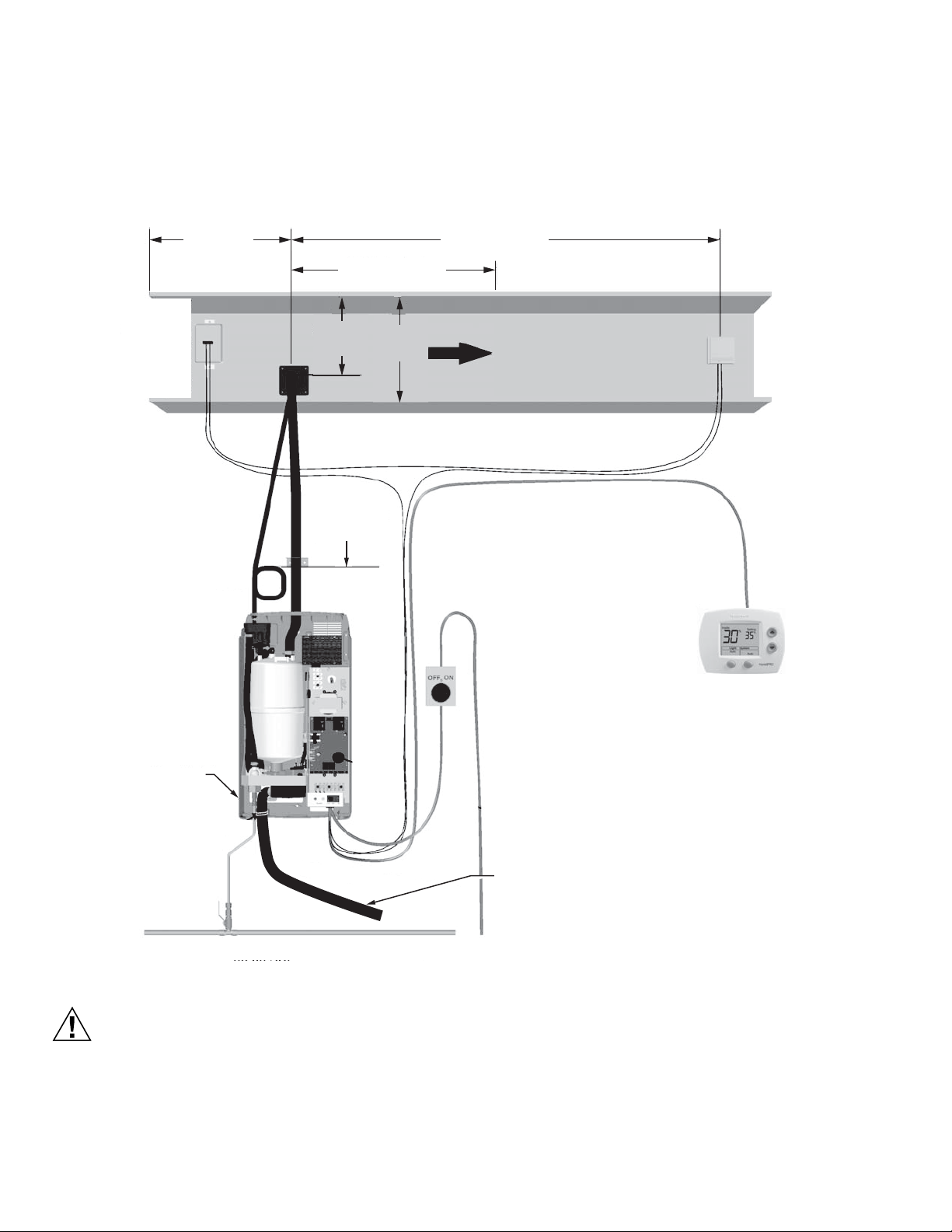
HM700A1000
PRECAUCIÓN
INTERRUPTOR DE DESCONEXIÓN CON FUSIBLES
TENSIÓN, AMPERAJE Y FASE CORRECTOS
SEGÚN LA ETIQUETA DE
ESPECIFICACIONES (OPCIONAL)
CONTROL DE HUMEDAD
EN EL CONDUCTO DE RETORNO
O LA UBICACIÓN QUE REPRESENTA EL
ESPACIO HUMIDIFICADO (ÁREA SIN
CORRIENTES DE AIRE, LEJOS DE
UNA PUERTA Y SIN DIFUSORES)
LÍNEA DE 1/2 IN (MÍNIMO) A UNA DISTANCIA MÁXIMA DE 4 FT (1.2 M). DE 30 A 100 PSIG
AIR GAP
SIFÓN EN
FORMA DE P
UNA CAÍDA MÍNIMA
DE 12 IN (30 CM)
CURVA U OTRA
OBSTRUCCIÓN
NOTA: TERMINALES U O HUM EN LAS SERIES ENTRE LOS
TERMINALES 1 Y 2
PRUEBA DE AIRE
(OPCIONAL)
EN SERIES ENTRE LOS
TERMINALES 1 Y 2.
QUITAR EL PUENTE DE
CONEXIÓN ENTRE LOS
TERMINALES 1 Y 8.
CONDUCTO CON UNA
ALTURA DOS
VECES MAYOR CON
RESPECTO A UN VENTILADOR
O UNA TRANSICIÓN
10 FT (3 M) COMO MÍN.
4 FT (1.2 M) COMO MÍN.
8 IN
(20 CM)
COMO MÍN.
LÍMITE MÁXIMO
ENCENDIDO/APAGADO
(OPCIONAL)
EN SERIES ENTRE LOS
TERMINALES 1 Y 2.
QUITAR EL PUENTE DE
CONEXIÓN ENTRE LOS TERMINALES 1 Y 8.
MS35807
CONDUCTO CON
UNA ALTURA
DE 2/3
MONTAJE
- UNIDAD NIVELADA
- TORNILLOS EN LA
PIEZA ESTRUCTURAL
LÍNEA DE VAPOR
- INCLINACIÓN ADECUADA
- LIBRE DE OBSTRUCCIONES
- MANGUERA LIBRE DE
DEFORMACIONES
- SIFONES DE CONDENSADO
EN TRAMOS LARGOS
ETIQUETA DE
ESPECIFICACIONES
LA TUBERÍA DE DESAGÜE DEBE DIRIGIRSE DE FORMA QUE
PERMITA EL FLUJO LIBRE DEL AGUA. CONSERVE LA PENDIENTE
ADECUADA, SIN RETENEDORES Y SIN TORCEDURAS.
PUESTA EN MARCHA
Verificación de la instalación
Antes de encender el HM700, inspeccione la instalación para asegurarse de que se realizó correctamente.
Riesgo de daño en el equipo
No deje el interruptor de encendido/apagado/desagüe
en la posición de desagüe por más de un ciclo
completo de desagüe. El solenoide de la válvula de
desagüe puede calentarse y dañar la válvula o los
cables. No intente drenar la unidad si no hay agua en
33-00118EFS—01 14
Fig. 19. Verificación de la instalación.
el sistema.
Encendido/apagado
El HM700 viene configurado de fábrica para funcionar como
un humidificador de encendido/apagado. Funcionará cuando
se suministre una corriente de 24 V CA desde el terminal 1 al
terminal 2 mediante un higrostato de encendido/apagado y
otros dispositivos de seguridad en serie.
Page 65
Procedimiento de puesta en marcha
ADVERTENCIA
1. Examine el humidificador para asegurarse de que no
presenta daños y compruebe que la instalación se haya
realizado correctamente.
2. Asegúrese de que el cilindro se encuentre debidamente
conectado a la válvula de desagüe y que los enchufes
de los electrodos estén insertados en las clavijas del
cilindro.
3. Asegúrese de que la cubierta frontal se encuentre
ubicada y asegurada con los tornillos de sujeción.
4. Abra la válvula de cierre de suministro de agua.
5. Conecte la alimentación principal mediante el
interruptor de desconexión instalado.
Riesgo de lesiones personales.
No se deben utilizar unidades dañadas o instaladas
incorrectamente. Las unidades dañadas o instaladas
incorrectamente pueden representar un riesgo tanto
para las personas como para la propiedad.
6. Coloque el interruptor de encendido/apagado en la
parte frontal del humidificador en la posición de encendido.
• El humidificador realizará una secuencia de
autodiagnóstico; durante esta secuencia, los LED y
los componentes internos se activarán
momentáneamente. Consulte “Luces LED
indicadoras de estado” en la página 16 para
obtener información sobre las luces LED y sus
secuencias.
• Si se detecta un error durante la secuencia de
autodiagnóstico, el humidificador no se iniciará. El
LED amarillo parpadeará en una secuencia
repetitiva para indicar que se detectó una falla.
Consulte las Tablas 7 y 8 para obtener información
sobre el diagnóstico y la corrección de fallas.
HM700A1000
• Después de la prueba del sistema, el humidificador
se encuentra en modo de funcionamiento normal.
7. Controle y ajuste el punto de referencia de control en el
control y en el higrostato de límite alto.
8. Cuando el higrostato externo genera una demanda de
humedad y el bucle de seguridad se encuentra cerrado,
la luz LED verde ubicada en la parte frontal del
humidificador se encenderá, el relé de tensión del
bloque de control se activará, la válvula de llenado
comenzará a funcionar (después del relé) y el cilindro
se llenará con agua lentamente.
NOTA: Mientras el cilindro se llena con agua, no debe
fluir agua por el desagüe. Si fluye agua por el
desagüe, esto indica que existe una
contrapresión excesiva o que la válvula de
desagüe presenta fugas. Consulte la sección
Localización y solución de problemas.
9. Si se utiliza un relé de habilitación del ventilador, la luz
LED verde continuará parpadeando hasta que se cierre
la prueba de aire. Luego de que se cierra la prueba de
aire, la luz LED verde dejará de parpadear y quedará
encendida de manera estática, y el humidificador
comenzará a generar vapor, tal como se describe en el
paso 8.
10. Tanto el calentamiento del agua por parte de los
electrodos sumergidos como la producción de vapor
tardarán de 5 a 10 minutos.
NOTA: Si la conductividad del agua es baja, es posible
que el HM700 necesite varias horas para alcanzar
su plena capacidad de producción. Esto es
normal. Durante este tiempo, el humidificador no
realizará ningún desagüe y la conductividad del
agua en el cilindro aumentará. Para acelerar este
proceso, agregue ¼ de cucharadita de sal al
cilindro. Esto aumentará la conductividad del
agua de inmediato e iniciará el calentamiento.
15 33-00118EFS—01
Page 66

HM700A1000
MS35828
STATUS
DRAIN OFF ON
AMARILLOVERDE
FUNCIONAMIENTO
Luces LED indicadoras de estado
La interfaz de usuario del HM700 incluye 2 luces LED que
brindan información sobre el estado del humidificador.
Fig. 20. Luces LED indicadoras de estado.
Parpadeo de las luces LED amarilla y verde
Indica que no hay una demanda de humedad.
Parpadeo de la luz LED amarilla
Indica que se detectó una falla y que el humidificador dejó
de funcionar. Cuente la cantidad de parpadeos y
consulte la Tabla 8 para obtener información.
Parpadeo de la luz LED verde
Indica que el humidificador se encuentra encendido, pero
que no hay demanda de humedad. El bucle de
seguridad (1-2) se encuentra abierto.
Luz LED amarilla encendida
Indica que el nivel de agua es alto.
Cuando la luz LED amarilla se encuentra encendida (no
parpadeando), indica que el sensor de exceso de agua
interrumpió el llenado del cilindro. La luz LED es solo
informativa; a menos que se mantenga encendida por
un periodo de tiempo prolongado, no requiere ninguna
acción.
Luz LED verde encendida
Indica que se está produciendo vapor.
Cómo seleccionar un punto de referencia de humedad relativa
El punto de referencia óptimo de la humedad depende de los
motivos por los cuales un espacio necesita ser humidificado.
El “ASHRAE Handbook HVAC Applications” (Manual de
aplicaciones de climatización de la Sociedad Americana de
Ingenieros sobre Calefacción, Ventilación y Aire
Acondicionado) recomienda una humedad relativa de diseño
específica para aplicaciones particulares.
Salud y confort: El beneficio de la humedad se relaciona
principalmente con la salud y el confort, en un rango de 40 a
60 %. Se recomienda una configuración de humedad de 45 a
50 %, a fin de evitar la humidificación excesiva.
Disminución de la temperatura: Por lo general, en climas
fríos es necesario reducir el nivel de humedad en un
ambiente acondicionado a fin de evitar la acumulación de
condensación en el interior de paredes, ventanas y molduras
exteriores. En estas condiciones, se recomienda utilizar la
función de disminución de humedad del control HumidiPRO
para evitar los daños producidos por la condensación. El
control digital, que incluye un sensor de temperatura exterior,
disminuirá el punto de referencia de la humedad de manera
automática, a fin de que se corresponda con la temperatura
exterior.
33-00118EFS—01 16
Page 67
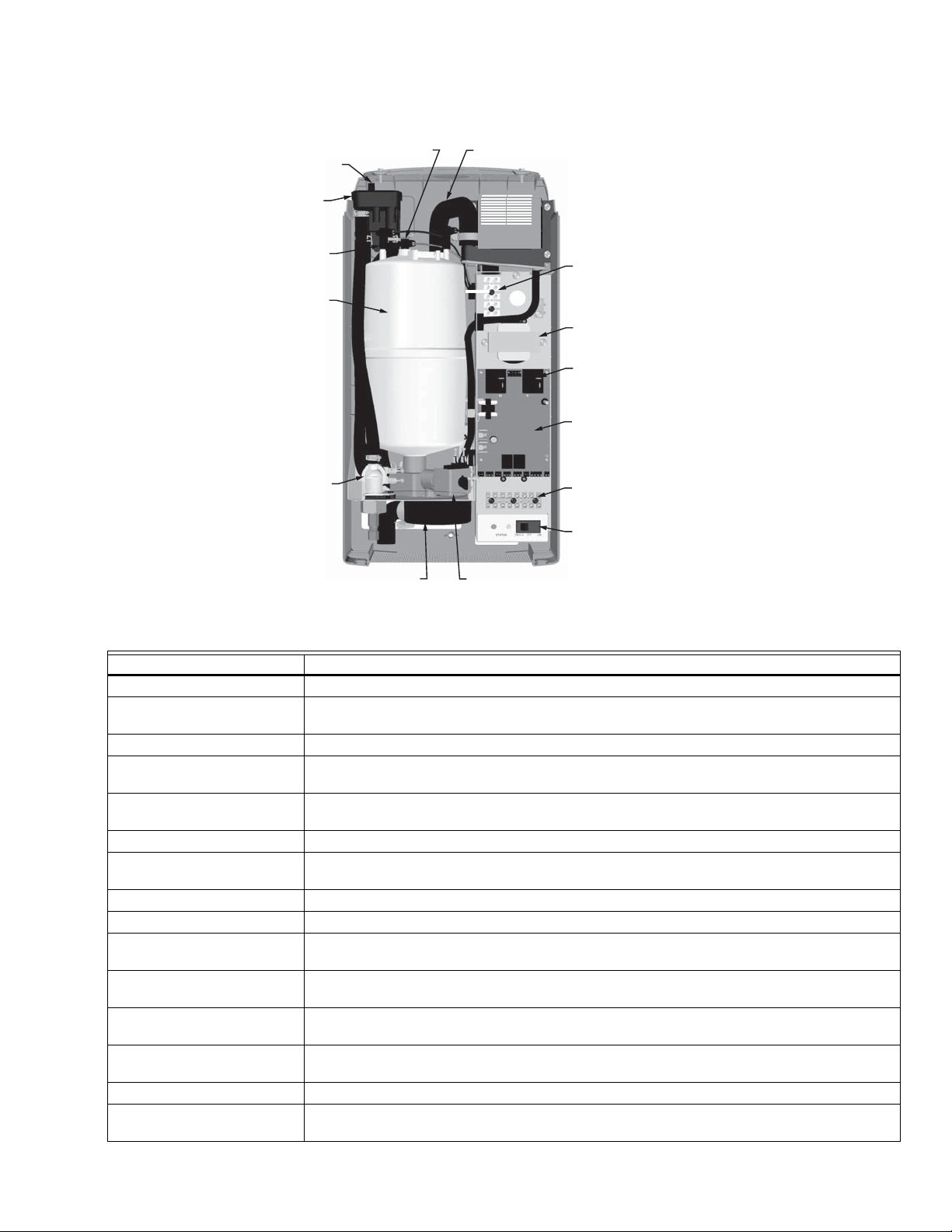
HM700A1000
SALIDA DE
VAPOR
RETORNO DEL
CONDENSADO
RECIPIENTE
DE LLENADO
VÁLVULA DE DESAGÜECANAL DE DESAGÜE
VÁLVULA DE
LLENADO
CILINDRO
ENCHUFE DEL
CILINDRO
ENCHUFE DEL
SENSOR DE
EXCESO DE AGUA
INTERRUPTOR DE
ENCENDIDO/
APAGADO/DESAGÜE
TABLERO DE
CONTROL
RELÉ DE TENSIÓN
BLOQUE DE
TERMINALES DE
ALTA TENSIÓN
TRANSFORMADOR
REGLETA DE
TERMINALES
DE CONTROL
MS35827
Fig. 21. Componentes del humidificador.
Componente Función
Retorno del condensado Proporciona una conexión para devolver el condensado al humidificador.
Regleta de terminales de
control
Banda terminal para la conexión entre los controles externos y el humidificador, y permite la
interacción con otros equipos.
Enchufe del cilindro Alimenta los conectores de los electrodos en el cilindro.
Cilindro Mantiene los electrodos en el agua. La corriente entre los electrodos genera calor que se utiliza
Canal de desagüe Combina el agua de desagüe del cilindro y el rebose del recipiente de llenado en una única
para producir vapor.
salida de desagüe.
Válvula de desagüe Desagota el agua del humidificador.
Tablero de control Controla todas las funciones del humidificador y brinda conexiones de entrada y salida a los
componentes del humidificador.
Recipiente de llenado Brinda un espacio de aire para evitar el reflujo.
Válvula de llenado Controla el flujo de agua en el humidificador.
Bloque de terminales de alta
tensión
Enchufe del sensor de exceso
Es la conexión de alimentación principal que va desde el interruptor de desconexión externo al
humidificador.
Se utiliza para detectar un nivel alto de agua en el cilindro.
de agua
Interruptor de
encendido/apagado/desagüe
Relé de tensión Enciende o interrumpe la alimentación a los electrodos del cilindro, conforme a la señal que
Enciende o interrumpe la alimentación al controlador del humidificador y vacía el cilindro.
Nota: Interrumpe la alimentación hacia el humidificador, apaga el interruptor de desconexión.
recibe del controlador del humidificador (instalado en el bloque de control).
Salida de vapor Conecta la línea de vapor a la manguera de vapor.
Transformador Disminuye la tensión principal a 24 V CA para que sea compatible con el controlador y los
componentes internos, como la válvula de llenado y de desagüe.
17 33-00118EFS—01
Page 68
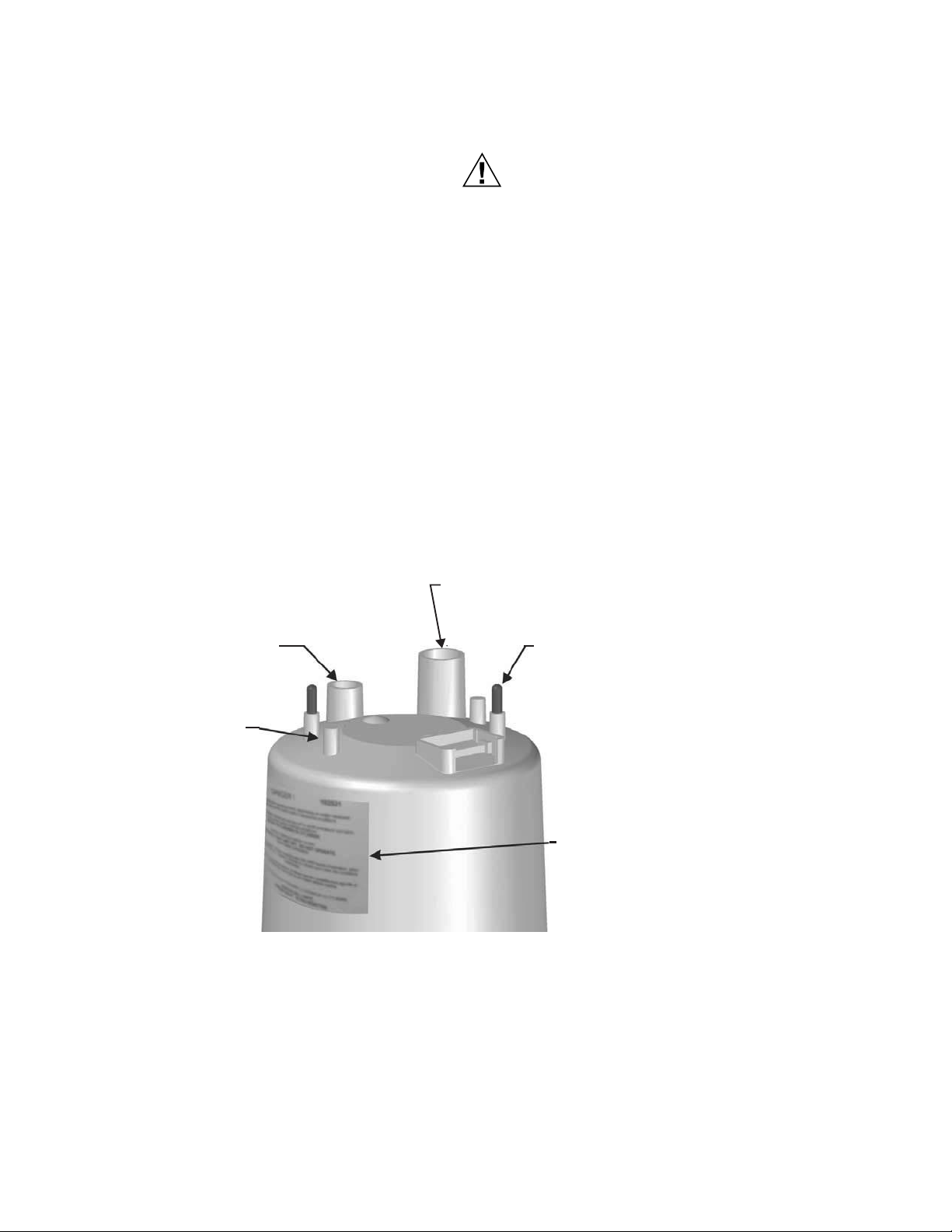
HM700A1000
PRECAUCIÓN
MS35704
PUNTO DE MONTAJE
INTERNO DE LOS
ELECTRODOS
LA CLAVIJA DEL SENSOR DE
EXCESO DE AGUA PRESENTA UN
ANILLO PLÁSTICO ALREDEDOR.
CONECTE EL CABLE ANARANJADO
DEL SENSOR DE EXCESO DE AGUA.
SALIDA DE VAPOR
ASEGURE LA MANGUERA DE VAPOR
A LA SALIDA CON UNA ABRAZADERA.
CLAVIJA DE LOS ELECTRODOS
CONECTE LOS ENCHUFES DEL CILINDRO
CODIFICADOS POR COLOR A LA CLAVIJA CON
LA ETIQUETA DE COLOR CORRESPONDIENTE.
EL ENCHUFE DE RESORTE DEBE CABER
PERFECTAMENTE EN LA CLAVIJA. SI QUEDA
FLOJO O PRESENTA SIGNOS DE DAÑO,
REEMPLÁCELO.
ETIQUETA
IDENTIFICA LA INFORMACIÓN DEL
CILINDRO. TAMBIÉN INCLUYE LA INFORM
ACIÓN DE SEGURIDAD Y LOS CONTACTOS.
MANTENIMIENTO Y REPARACIONES
Mantenimiento requerido
El humidificador HM700 ha sido diseñado para requerir muy
poco mantenimiento. El mantenimiento regular consiste en la
supervisión del humidificador para garantizar que se
encuentra en buenas condiciones, el reemplazo del cilindro
cuando el software indica que está desgastado y la limpieza
de la válvula de desagüe cada vez que se reemplaza el
cilindro.
DESGASTE DEL CILINDRO
Cuando el cilindro se encuentra desgastado, el HM700 dejará
de funcionar y la luz LED amarilla parpadeará en una
secuencia repetitiva de 4 parpadeos. Consulte la Tabla 8 de la
página 24 para obtener información sobre otras secuencias
de parpadeo. En este momento, se debe reemplazar el
cilindro.
El cilindro de vapor es desechable y debe ser reemplazado
cuando finalice su vida útil. La vida útil del cilindro depende de
las condiciones del suministro de agua y del uso del
humidificador.
NOTA: El HM700 cuenta con un zuncho reutilizable que
CILINDRO DE REEMPLAZO
La etiqueta del cilindro existente incluye el tipo de cilindro en
la esquina superior izquierda. Cuando solicite un cilindro,
siempre mencione el número de modelo de tres o cinco
dígitos que aparece en la etiqueta, el número de serie del
humidificador y la tensión del humidificador. El número de
serie y la tensión se encuentran en la etiqueta de
especificaciones que aparece en el lado izquierdo del
humidificador.
El hecho de no reemplazar el cilindro cuando
finaliza su vida útil resultará en un funcionamiento
inadecuado, así como en daños al humidificador.
Honeywell no se hace responsable por los daños
ocasionados como resultado de, o atribuidos a, la
falta de reemplazo de un cilindro desgastado
(consultar la sección “Garantía del fabricante”).
asegura el cilindro durante el traslado y la
instalación doméstica. Este zuncho puede
retirarse o aflojarse para quitar el cilindro.
Asegúrelo luego de instalar el nuevo cilindro.
33-00118EFS—01 18
Fig. 22. Cilindro del HM700 (HM700ACYL2).
Page 69
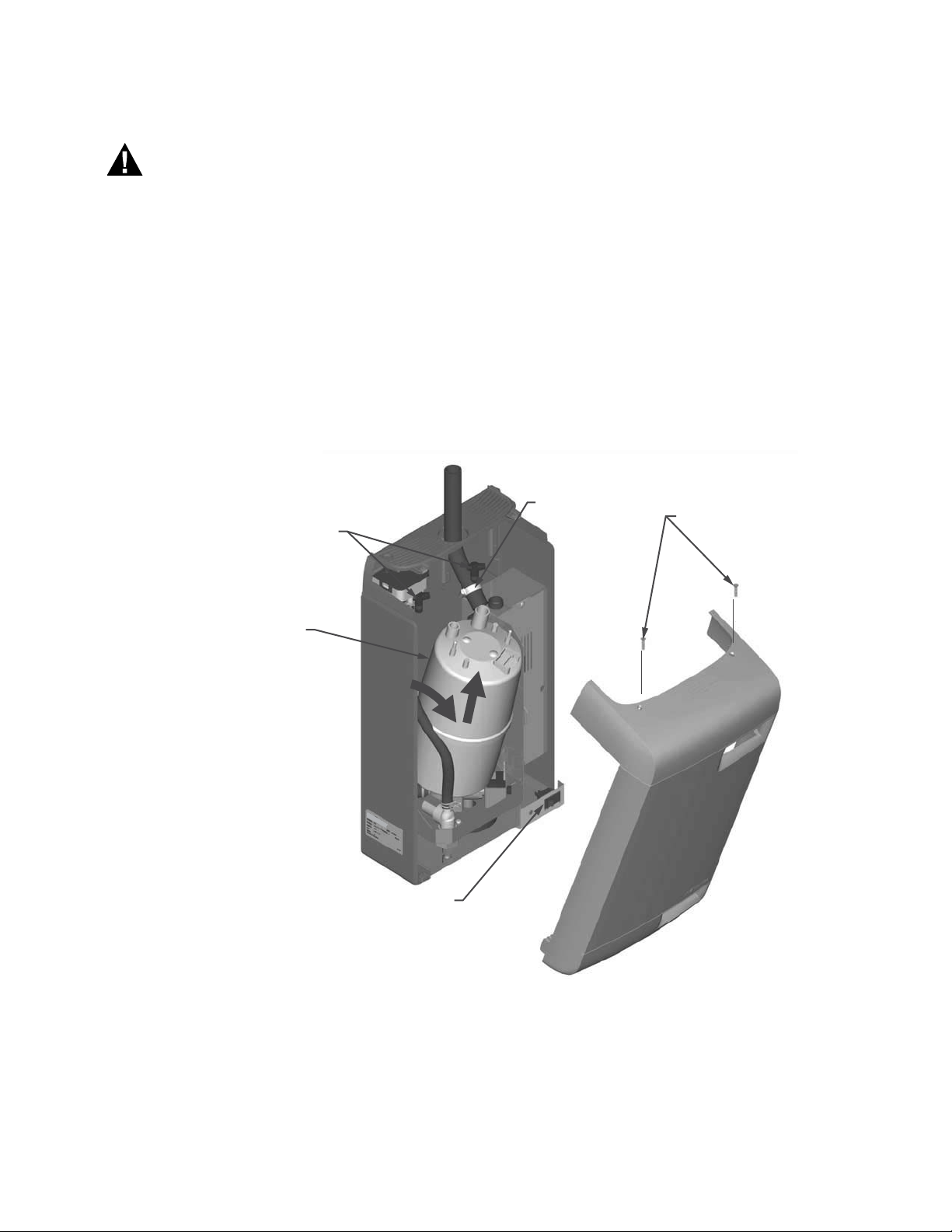
HM700A1000
ADVERTENCIA
A
Cómo quitar el cilindro
Antes de realizar cualquier tarea de
mantenimiento, desconecte la fuente de
alimentación principal del interruptor de
desconexión externo.
El interior del gabinete del humidificador contiene
componentes y cables de alta tensión. El acceso debe
limitarse solo al personal autorizado.
1. Para drenar el cilindro existente, coloque el interruptor
de encendido/apagado/desagüe en la posición de
desagüe. Deje drenar el humidificador hasta que no
salga más agua (por lo general tarda 10 minutos
máximo).
2. Coloque el interruptor de encendido/apagado/desagüe
en la posición de apagado.
LEVANTAR EL
ENCHUFE DEL
CILINDRO DE
FORMA VERTICAL
3. Cierre la válvula de cierre de suministro de agua.
4. Interrumpa la alimentación al humidificador a través del
interruptor de desconexión externo.
5. Quite los dos tornillos que fijan la cubierta frontal.
6. Para quitar los enchufes del cilindro de las clavijas, jale
de forma vertical.
7. Con un destornillador plano, afloje la abrazadera de la
manguera donde la manguera se conecta al cilindro.
8. Incline la parte superior del cilindro hacia adelante para
retirarlo de la manguera de vapor. Luego de
desconectarlo de la manguera de vapor, levante el
cilindro.
NOTA: The HM700 has a re-usable tie strap to secure the
cylinder for transit as well as home installation.
This must be removed or loosened to remove the
cylinder. Secure when new cylinder is installed.
ABRAZADERA DE
LA MANGUERA
TORNILLOS DE LA CUBIERTA
CILINDRO
INCLINAR EL CILINDRO HACIA
DELANTE PARA DESCONECTARLO
DE LA MANGUERA; LUEGO,
LEVANTARLO PARA RETIRARLO
DE LA VÁLVULA DE DESAGÜE.
INCLINAR LA
CUBIERTA
INTERRUPTOR DE
ENCENDIDO/APAGADO/DESAGÜE
PARA RETIRAR
MS35705
Fig. 23. Cómo quitar el cilindro.
19 33-00118EFS—01
Page 70
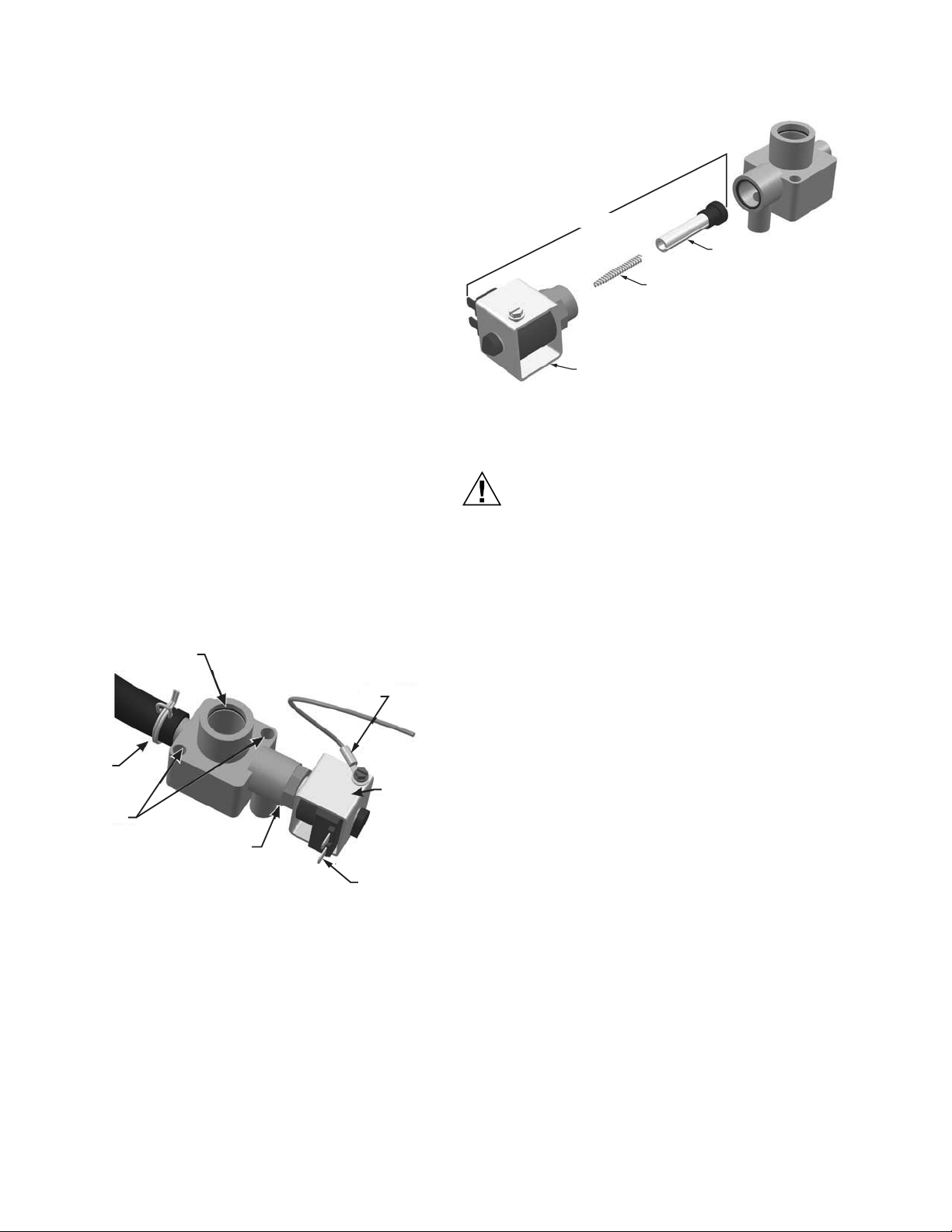
HM700A1000
PRECAUCIÓN
PUERTO DEL CILINDRO
Y JUNTA TÓRICA
CABLE A
TIERRA
SOLENOIDE
CONECTORES
DE HORQUILLA
TUERCA DE LATÓN
(ACTUADOR)
TORNILLOS
MANGUERA Y
ABRAZADERA
DE MANGUERA
MS35700
MS35707
MANGA Y
SOLENOIDE
RESORTE
(VER LA ORIENTACIÓN)
ÉMBOLO
ACTUADOR
Limpieza de la válvula de desagüe
Antes de instalar un cilindro nuevo, siempre limpie la válvula
de desagüe. Es posible que caigan incrustaciones desde el
cilindro desgastado a la válvula de desagüe e impidan el
funcionamiento correcto. Para limpiar la válvula de desagüe
correctamente, quítela y desármela.
1. Desconecte los terminales de horquilla de la válvula de
desagüe.
2. Quite los dos tornillos que fijan la válvula a la bandeja
de desagüe.
3. Escurra las aletas de la abrazadera de resorte que fija
la manguera a la válvula de desagüe y deslícela por la
manguera. Quite la manguera de la válvula de desagüe.
Levante la válvula de desagüe de la bandeja de
desagüe.
4. Abra la tapa roja de la bobina del solenoide y quite el
solenoide de la válvula.
5. Con una llave inglesa, afloje la tuerca de latón que fija el
actuador a la cubierta plástica y desarme el actuador.
6. Limpie los componentes del actuador y la cubierta de la
válvula (puerto de entrada, puerto de salida y puerto del
cilindro). Coloque la junta tórica nueva, que se
proporcionó, con el nuevo cilindro en la válvula.
7. Vuelva a armar el actuador y asegúrese de orientar el
extremo cerrado del resorte tal como se muestra en la
Fig. 25. Ajuste la tuerca de latón 1/4 después de
apretarla con la mano.
8. Limpie el extremo de la manguera y conéctela a la
válvula. Deslice la abrazadera de la manguera hasta
colocarla en su lugar y ubique la válvula en la bandeja
de desagüe.
9. Fije la válvula a la bandeja de desagüe con 2 tornillos.
Fig. 24. Válvula de desagüe.
Fig. 25. Ensamble del actuador de la válvula de desagüe.
Cómo instalar el nuevo cilindro
Asegúrese de que el nuevo cilindro sea un
HM700ACYL2. El uso de cilindros restaurados o
de otro modelo anulará la garantía del HM700.
1. Conecte el cilindro en la válvula de desagüe. Incline el
cilindro hacia adelante y conecte el extremo de la
manguera de vapor a la salida de vapor. Coloque el
cilindro nuevamente en su lugar.
2. Ajuste la abrazadera de la manguera; tenga cuidado de
no ajustarla demasiado porque puede romper la salida
de vapor plástica del cilindro.
3. Conecte los enchufes codificados por color a las
clavijas codificadas por color correspondientes.
Presione completamente. Conecte el enchufe del
sensor de exceso de agua. Los enchufes de resorte
deben ajustarse perfectamente en las clavijas del
cilindro. Si quedan flojos o presentan daños,
reemplácelos.
4. Vuelva a atar los zunchos.
5. Vuelva a colocar la cubierta del humidificador y
asegúrela con dos tornillos.
6. Conecte la alimentación al humidificador a través del
interruptor de desconexión externo.
7. Abra la válvula de cierre de suministro de agua.
8. Coloque el interruptor de encendido/apagado/desagüe
en la posición de encendido.
33-00118EFS—01 20
Page 71

HM700A1000
Periodo de inactividad prolongado
Si es necesario desconectar la alimentación del humidificador
por un periodo de inactividad prolongado, siempre asegúrese
de drenar el cilindro.
1. Coloque el interruptor de encendido/apagado/desagüe
en la posición de desagüe.
2. Espere hasta que el humidificador esté completamente
vacío (por lo general se vacía en menos de 10 minutos).
3. Coloque el interruptor de encendido/apagado/desagüe
en la posición de apagado.
4. Interrumpa la alimentación al humidificador a través del
interruptor de desconexión externo.
5. Cierre la válvula de cierre de suministro de agua.
NOTA: Si no hay una demanda de humedad por un
periodo de tiempo prolongado, el HM700 drenará
el cilindro automáticamente mientras esté
encendido. Esta función reducirá o evitará la
formación de corrosión en los electrodos y la
acumulación de algas y bacterias en el cilindro.
El cilindro permanecerá vacío hasta que se
registre una demanda de humedad; en ese
momento, la válvula de llenado se abrirá y llenará
el cilindro. La unidad realizará su proceso normal
y funcionará de manera óptima.
CÓMO PONER LA UNIDAD EN MARCHA LUEGO DE UN
PERIODO DE INACTIVIDAD PROLONGADO
1. Compruebe que el humidificador no se encuentre
dañado y que la instalación no haya sido modificada.
Consulte “Procedimiento de puesta en marcha” en la
página 15.
2. Conecte la alimentación al humidificador a través del
interruptor de desconexión externo.
3. Coloque el interruptor de encendido/apagado/desagüe
en la posición de desagüe.
4. Espere hasta que no fluya agua por el desagüe. Por lo
general, esto tarda menos de 10 minutos.
5. Siga el procedimiento de puesta en marcha que se
indica en la página 15.
21 33-00118EFS—01
Page 72
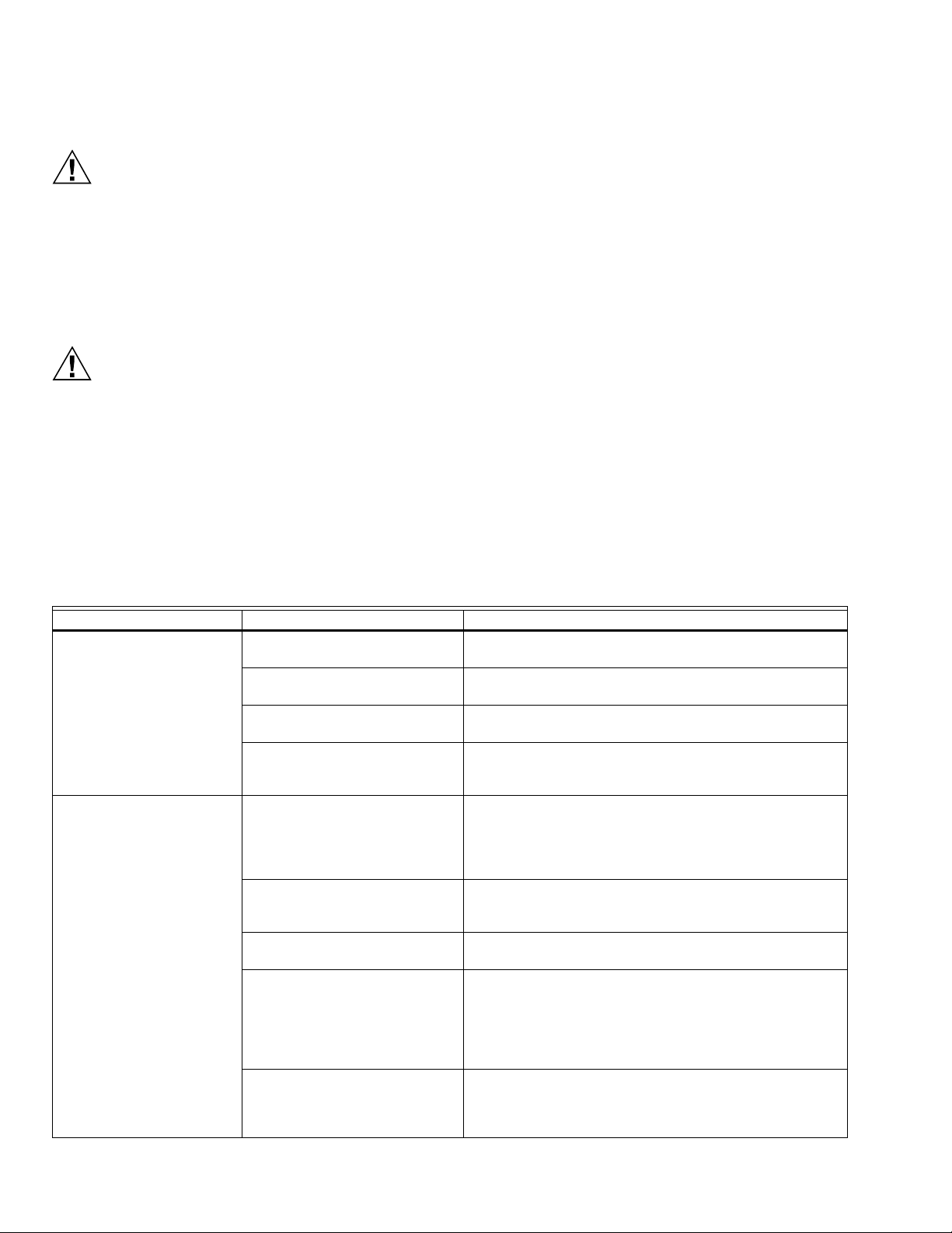
HM700A1000
PRECAUCIÓN
PRECAUCIÓN
LOCALIZACIÓN Y SOLUCIÓN DE PROBLEMAS
sistema. A menudo, la falla está relacionada con
una conexión de la manguera defectuosa o con
Peligro de alta tensión.
Recuerde que, durante la localización y solución de
problemas, el humidificador se encuentra alimentado
por una tensión alta; se recomienda familiarizarse
tanto con las buenas prácticas como con el cableado
del humidificador. Cualquier tarea de localización y
solución de problemas que requiera la apertura del
gabinete debe ser realizada por un profesional
autorizado.
Riesgo de quemaduras y escaldaduras.
Cuando la temperatura del agua o el vapor superan
los 120 °F (49 °C) puede producir quemaduras y
escaldaduras.
NOTA: La mayoría de las fallas del humidificador se
deben a una instalación deficiente, y no a fallas
del equipo. Un diagnóstico completo de fallas
siempre incluye un análisis detallado de todo el
REQUISITOS DE LOCALIZACIÓN Y SOLUCIÓN DE
PROBLEMAS
• Asegúrese de que la instalación cumpla con los requisitos
• Lea el capítulo sobre funcionamiento de este manual para
• Encuentre el diagrama de cableado específico de su
• Si contacta a su representante local o a Honeywell para
La siguiente sección brinda pautas generales para la
localización y solución de problemas del humidificador HM700
y los componentes auxiliares. Para obtener información
detallada sobre la localización y solución de problemas,
consulte los manuales suministrados con el equipo auxiliar y
la Tabla 8, “Localización y solución de problemas del HM700”,
en la página 24.
el sistema de control de la humedad.
de instalación mencionados en el capítulo sobre
instalación de este manual.
familiarizarse con el funcionamiento del humidificador.
humidificador en el interior de la puerta del humidificador.
Además, se incluye una copia genérica del diagrama de
cableado de HM700 al final de este capítulo para fines de
consulta.
obtener ayuda, asegúrese de conocer el número de serie.
Problema Causa Medidas correctivas
No hay actividad cuando se
enciende el interruptor de
encendido/apagado.
El humidificador no humidifica o no
alcanza el punto de referencia del
HM700.
Tabla 7. Localización y solución de problemas generales.
El fusible está quemado. Controle el fusible en línea ubicado entre el transformador y el bloque de
control.
La tensión es incorrecta. Compruebe la tensión que aparece en la etiqueta de especificaciones y
corríjala.
El transformador reductor no genera una
tensión de 24 V CA.
El puente de conexión de la alimentación
principal es incorrecto.
El bucle de seguridad está abierto. Compruebe que haya una tensión de 24 V CA en el terminal 2.
No hay una señal de demanda. Verifique la tensión entre los terminales 3 y 4. Con respecto a la
La capacidad se limitó manualmente. Verifique el potenciómetro con ajuste manual de la capacidad. Gírelo hacia
La conductividad del agua es baja. Compruebe si la luz LED amarilla se encuentra encendida. Si la
No hay flujo de aire en el conducto. Compruebe que los terminales de habilitación del ventilador del
Reemplace el transformador.
Compruebe que el puente de conexión ubicado en el bloque de terminales
de alta tensión se encuentre conectado entre el terminal P y el terminal
correspondiente a la tensión de alimentación. Consulte la Fig. 16.
Compruebe el cableado y el funcionamiento de los dispositivos de
encendido/apagado conectados a los terminales 1 y 2.
Compruebe que el puente de conexión se encuentre instalado en el bucle
de seguridad de la prueba de aire, entre los terminales 1 y 8.
configuración de la demanda, debe existir una señal a escala completa del
35 % para que el humidificador comience a funcionar.
la derecha para aumentar la capacidad.
conductividad del agua es baja, es posible que el HM700 necesite varias
horas para alcanzar su plena capacidad de producción. Esto es normal.
Durante este tiempo, el humidificador no realizará ningún desagüe y la
conductividad del agua en el cilindro aumentará. Si desea aumentar la
conductividad más rápido, agregue 1/4 de cucharadita de sal al cilindro.
humidificador (terminales 19 y 20) se encuentren debidamente conectados
al sistema de calefacción. Verifique que la prueba de aire se encuentre
conectada al terminal 8.
33-00118EFS—01 22
Page 73
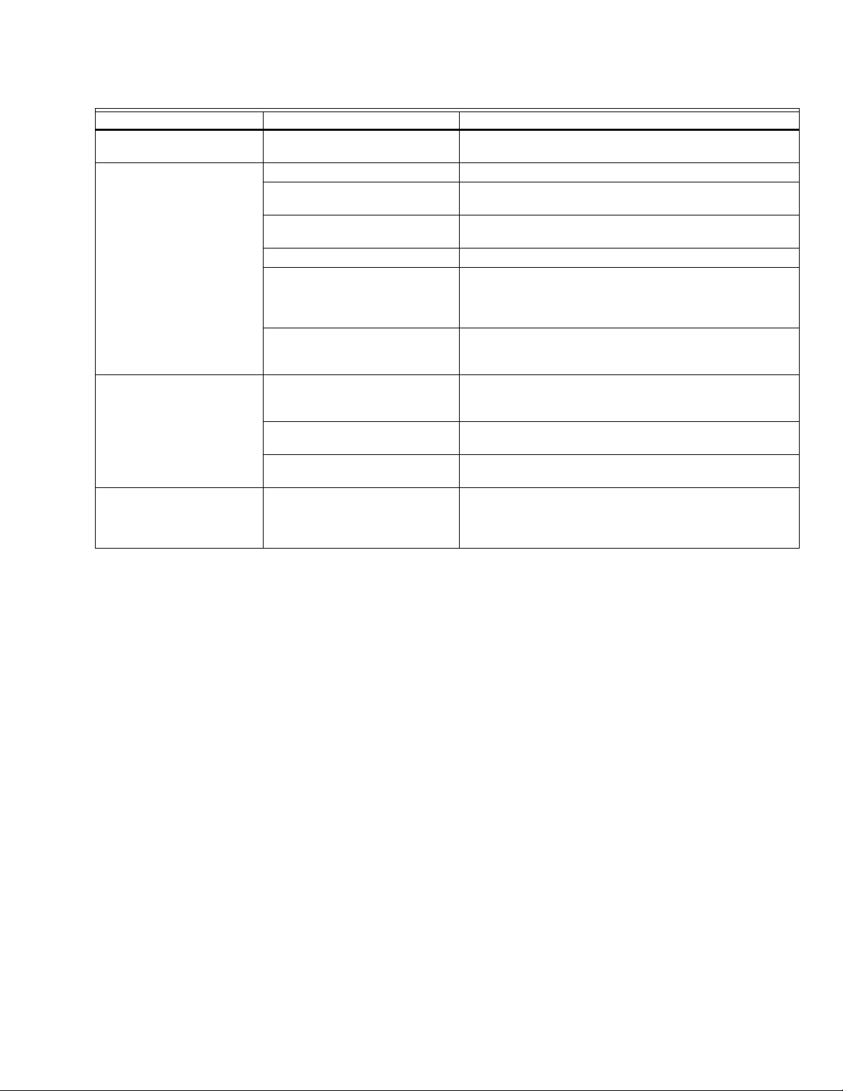
Tabla 7. Localización y solución de problemas generales. (Continuación)
Problema Causa Medidas correctivas
El humidificador falló y la luz LED
amarilla parpadea.
El software detectó una condición
anormal.
Consulte la Tabla 8 en la página 24.
Sale agua del distribuidor. El distribuidor no se encuentra nivelado. Use un soporte al final de distribuidor para nivelarlo.
El sifón en forma de “P” se encuentra muy
cerca del distribuidor.
La línea de condensado no está lo
suficientemente inclinada.
El sifón en forma de “P” debe ubicarse 12 in (30 cm) por debajo del
distribuidor para garantizar el flujo. Si es necesario, vuelva a ubicarlo.
Es necesario que presente la inclinación adecuada. Si es necesario,
vuelva a instalarla.
El sifón está obstruido. Compruebe el flujo de agua por el sifón. Si está bloqueado, límpielo.
La línea de vapor no está aislada. Si la línea de vapor es larga, es posible que la acumulación de
condensado haya sobrecargado el puerto de condensado del distribuidor.
Aísle la línea para mejorar la eficiencia e instale sifones de condensado
adicionales, tal como se requiere.
La línea de vapor está instalada
incorrectamente.
Verifique que la línea de vapor se haya instalado con sifones de
condensado y presente la inclinación adecuada. Consulte “Instrucciones
de retorno del condensado y las líneas de vapor” en la página 9.
El conducto presenta condensado. No se dejaron los espacios recomendados
para la instalación.
Consulte el manual de instalación del distribuidor para obtener información
sobre los espacios requeridos. Si es necesario, vuelva a ubicar el
distribuidor.
Las condiciones de diseño se modificaron. Compruebe la temperatura y la humedad del aire de suministro para
determinar si las condiciones han cambiado.
El higrostato de límite alto no funciona. Verifique la configuración y el funcionamiento del higrostato de límite alto.
Si está dañado, reemplácelo.
El humidificador activa el interruptor
diferencial.
El humidificador se encuentra conectado a
un circuito de interruptor diferencial. El
cable a tierra de la válvula de desagüe no
Para obtener información sobre el interruptor diferencial y el desmontaje
del cable a tierra, revise los pasos para la instalación eléctrica y las notas
que aparecen en la página 11.
se encuentra conectado
HM700A1000
23 33-00118EFS—01
Page 74

HM700A1000
Fallas del HM700
El sistema de autodiagnóstico incorporado del HM700 realice
está continuamente monitorizando el funcionamiento del
humidificador. Si se produce una condición anormal que el
software no puede corregir, el HM700 interrumpirá la
alimentación del cilindro, lo desagotará e indicará la falla
mediante la luz LED amarilla.
Cómo resolver una falla
• Compruebe el significado de la secuencia de parpadeo en
la lista de mensajes de falla y realice todas las medidas
necesarias para corregir la causa, tal como se detalla en la
Tabla 8 de la página 24.
• Utilice el interruptor de encendido/apagado para
desconectar y volver a conectar la alimentación del
humidificador luego de 10 segundos.
Secuencia de parpadeo de la luz LED
Para diferenciar las varias condiciones de falla, la luz LED
amarilla parpadea en distintas secuencias. La Tabla 8
enumera las secuencias de falla, sus significados, las causas
posibles y las medidas correctivas recomendadas.
Tabla 8. Localización y solución de problemas del HM700.
Luz LED
amarilla Problema Causa Medidas correctivas
1 parpadeo Corriente excesiva
La corriente superó el
máximo de 130 %.
2 parpadeos Sin corriente
La válvula de llenado
estuvo activada por
mucho tiempo, pero no
se alcanzó un nivel alto
de agua.
El llenado debe ser
superior a 1” por minuto.
El desagüe está bloqueado y se produjo una
acumulación de agua.
El solenoide de desagüe no está energizado y
se produjo una acumulación de agua.
El llenado se produjo muy rápido; la válvula de
llenado está dañada y presenta fugas.
El llenado se produjo muy rápido; la válvula de
llenado no es correcta.
La conductividad del agua de suministro es
muy alta.
El ciclo de humidificador es corto. a) Verifique si el higrostato de límite alto u otro control de
El cilindro instalado es incorrecto. Instale el modelo correcto de cilindro.
El cilindro está desgastado, pero el software
no detectó esta condición.
Hay condensado de otra fuente. Quite el condensado que no se encuentre en la línea de vapor.
Hay contrapresión. Elimine la contrapresión.
La válvula de desagüe presenta fugas o está
atascada en posición abierta.
La válvula de cierre de agua está cerrada. Abra la válvula de cierre.
El filtro de la válvula de llenado está
bloqueado.
El sistema presenta una contrapresión alta. a) Compruebe que la manguera no esté doblada.
El sensor de exceso de agua no está
conectado.
La conductividad del agua es baja. a) Verifique que se suministre agua potable a la unidad, y no agua
Limpie la línea de desagüe.
Controle y corrija el cableado de la válvula de desagüe.
Reemplace la válvula de llenado.
La válvula de llenado puede presentar fallas; reemplácela si es
necesario.
a) Cambie el suministro de agua.
b) Contacte a un representante de Honeywell para obtener
recomendaciones.
encendido/apagado se apaga y se enciende en menos de 5
minutos. Verifique la ubicación y la configuración del higrostato de
límite alto.
b) Para disminuir la producción, reduzca el potenciómetro.
Reemplace el cilindro (consulte el capítulo sobre mantenimiento).
Limpie o reemplace la válvula de desagüe (consulte el capítulo
sobre mantenimiento).
Limpie el filtro ubicado en la entrada de la válvula de llenado.
b) Compruebe que se haya eliminado todo el condensado (consulte
la sección sobre instalación).
Compruebe que el enchufe del cilindro de color blanco esté
conectado al electrodo corto, que se encuentra dentro de un
recipiente plástico, y al bloque de control.
tratada (depurada por ósmosis inversa o desionizada).
b) Compruebe la conductividad del agua. Si es menor que 150 μS,
agregue 1/4 de cucharadita de sal al recipiente de llenado y reinicie
la unidad.
33-00118EFS—01 24
Page 75

Luz LED
amarilla Problema Causa Medidas correctivas
3 parpadeos Sin corriente, nivel de
agua alto
El nivel de agua alcanzó
la parte superior del
cilindro, pero no hay
corriente.
El cable primario no se encuentra conectado
al transformador de corriente.
El enchufe del sensor de exceso de agua está
conectado a la clavija de un electrodo.
El enchufe del cilindro no está instalado
correctamente.
Vuelva a conectar el cable primario al transformador de corriente.
Instale el enchufe del sensor de exceso de agua en la clavija del
cilindro que presenta un anillo alrededor.
Verifique que los colores de los enchufes del cilindro coincidan con
los indicadores que se encuentran junto a los electrodos en el
cilindro; además, compruebe que el enchufe del cilindro de color
blanco se encuentre conectado al electrodo corto ubicado en un
recipiente plástico.
4 parpadeos Cilindro desgastado
Los electrodos están
cubiertos de
Los electrodos del cilindro están cubiertos con
incrustaciones y el humidificador no puede
satisfacer la demanda de humedad.
Reemplace el cilindro por un cilindro con el mismo número de
modelo (consulte el capítulo sobre mantenimiento).
incrustaciones.
HM700A1000
25 33-00118EFS—01
Page 76

HM700A1000
POTENCIÓMETRO
P8
EXCESO
DE AGUA
K2
K3
P1 P2 P3 P4 P5 P6 P7
240/208/
120 V CA
24 V CA
1.5 AMPERIOS
CILINDRO
V. DE LLENADO
V. DE DESAGÜE
1
2
3
4
8
19
20
21
R / HUM
AP
GF
RF
C
HUM
N/A
N/A
120L1
EXTERNO
INTERNO
240 P
INTERRUPTOR
DE ENCENDIDO/
APAGADO/
DESAGÜE
TRANSFORMADOR
N/A
120L1
240 P
S
LÁMPARAS INDICADORAS
DE ESTADO
G
Y
NOTA: INSTALE EL PUENTE DE CONEXIÓN DESDE EL TERMINAL
PTO CORRESPONDIENTE A LA TENSIÓN PRINCIPAL.
CALIENTE
NEUTRO
TIERRA
CALIENTE
CALIENTE
TIERRA
240 V CA
120 V CA
NOTA:
PUNTOS SECOS PARA EL VENTILADOR
DEL SISTEMA DE CALEFACCIÓN HABILITADOS.
SOLO CONTROL DE LA VÁLVULA PILOTO DE 24 V.
NC
TERMINAL INSTALADO EN FÁBRICA
CONTROL
DE HUMEDAD
24 V
LLAMADA
DE HUM
MS35721
33-00118EFS—01 26
Fig. 26. Diagrama de cableado.
Page 77

HM700A1000
GARANTÍA DE 5 AÑOS
Honeywell garantiza que este producto no tiene defectos de mano de obra ni en los materiales bajo condiciones de uso y
servicio normales durante un período de cinco (5) años desde la fecha de compra por parte del consumidor. Si en cualquier
momento, durante el período de vigencia de la garantía, se determina que el producto está defectuoso o no funciona
adecuadamente, Honeywell lo reparará o lo reemplazará (a elección de Honeywell).
Si el producto está defectuoso,
(i) llévelo al lugar donde lo compró, junto con la factura de compra u otra prueba de compra que incluya la fecha en la que
compró el producto; o
(ii) comuníquese con el Servicio de atención al cliente de Honeywell, llamando al 1-800-468-1502. En el Servicio de atención al
cliente determinarán si el producto debe ser devuelto a la siguiente dirección:
Honeywell Return Goods, Dock 4 MN10-3860, 1985 Douglas Dr. N., Golden Valley, MN 55422, o si se le puede enviar un
producto de reemplazo.
Esta garantía no cubre los gastos de remoción ni de reinstalación. Esta garantía no se aplicará si Honeywell demuestra que el
defecto fue causado por daños que se produjeron mientras el producto estuvo en posesión de un consumidor.
La única responsabilidad de Honeywell será la de reparar o reemplazar el producto dentro de los términos mencionados
anteriormente. HONEYWELL NO SERÁ RESPONSABLE POR LA PÉRDIDA NI EL DAÑO DE NINGÚN TIPO, QUE INCLUYE
CUALQUIER DAÑO INCIDENTAL O CONSECUENTE QUE RESULTE, DIRECTA O INDIRECTAMENTE, DE CUALQUIER
INCUMPLIMIENTO DE CUALQUIER GARANTÍA, EXPRESA O IMPLÍCITA, O DE CUALQUIER OTRA FALLA DE ESTE
PRODUCTO Algunos estados no permiten la exclusión o limitación de los daños fortuitos o resultantes, por lo que esta limitación
podría no aplicarse en su caso.
ESTA GARANTÍA ES LA ÚNICA GARANTÍA EXPRESA QUE HONEYWELL REALIZA SOBRE ESTE PRODUCTO. LA
DURACIÓN DE CUALQUIERA DE LAS GARANTÍAS IMPLÍCITAS, INCLUYENDO LAS GARANTÍAS DE COMERCIABILIDAD O
DE APTITUD PARA UN FIN DETERMINADO, ESTÁN LIMITADAS A LOS CINCO AÑOS DE DURACIÓN DE ESTA GARANTÍA.
Algunos estados no permiten limitaciones en relación a la duración de una garantía implícita, de manera tal que la limitación
anterior puede no aplicarse en su caso. Esta garantía le otorga derechos legales específicos, pero es posible que usted goce de
otros derechos que varían de un estado a otro.
Si tiene preguntas acerca de esta garantía, escriba a Honeywell Customer Relations, 1985 Douglas Dr. Golden Valley, MN 55422
o llame al 1-800-468-1502.
IMPORTANTE
Para mantener la garantía, solo deben utilizarse piezas y cilindros aprobados por Honeywell en el producto.
27 33-00118EFS—01
Page 78

HM700A1000
33-00118EFS—01 28
Page 79

HM700A1000
29 33-00118EFS—01
Page 80

HM700A1000
Automatización y control desenlace
Honeywell International Inc.
1985 Douglas Drive North
Golden Valley, MN 55422
customer.honeywell.com
® Marca Registrada en los Estados Unidos
© 2016 Honeywell International Inc. todos
33-00118EFS—01 M.S. 03-16
Impreso en Estados Unidos
 Loading...