

Page 1
TrueSTEAM
69-2036EFS-07
As Easy as 1-2-3-4
PROFESSIONAL INSTALLATION GUIDE
1
3
Mount
Plumb
2
4
Hang
Wire
See inside for detailed instruction and remote mounting options!
Page 2

Installation Guide
Table of ConTenTs
Installation Recommendations ...................................................... 1
List of tools/supplies ...................................................................... 2
Safety Precautions ......................................................................... 3
Duct Mount Instructions
Installation ....................................................................................... 4
Remote Mount Instructions
Installation ....................................................................................... 6
Plumbing and Wiring
Plumbing ....................................................................................... 12
Wiring ............................................................................................ 13
DIP Switch Selection .....................................................................17
Troubleshooting ............................................................................ 18
Cleaning and Seasonal or Vacation Maintenance ...................... 22
Additional Information
Parts List ....................................................................................... 24
Need Help?
For assistance with this product please visit http://yourhome.honeywell.com
or call Honeywell Customer Care toll-free at 1-800-468-1502
Read and save these instructions.
® U.S. Registered Trademark.
Patents pending.
Copyright © 2008 Honeywell International Inc. All rights reserved.
69-2036EFS—07 ii
Page 3
TrueSTEAM Humidification System
Make your TrueSTEAM installations accurate and efficient by addressing these commonly asked
questions:
Sizing for the Job
1. Selecting the appropriate humidifier for the job is critical:
The table below illustrates the square footage a TrueSTEAM humidifier can serve.
It is not recommended to install a 6 gallon device in a home larger than 2000 square feet.
Square Feet of Space 500 1000 1500 2000 2500 3000
ARI* Recommended Output Delivery (GPD) 0.1 2.2 4.4 6.5 8.6 11.7
TrueSTEAM HM512 - True 12 Gallons
TrueSTEAM HM509 - True 9 Gallons
TrueSTEAM HM506 - True 6 Gallons
* ARI Guideline F-2007 for maintaining 35% RH in a tight, residential four-person home with
8-ft. ceilings. Outdoor conditions = 20ºF and 70% RH.
Installation Check-out List
• Install the in-line water filter and back-flow prevention valve.
• Check that the main water supply line is open.
• Ensure there are no water leaks/drips at any of the water connections.
• Plug into a circuit with at least enough capacity to power the unit.
• Generate a call for humidity from the control and ensure TrueSTEAM fills and the Humidify
light turns on, indicating steam is being generated.
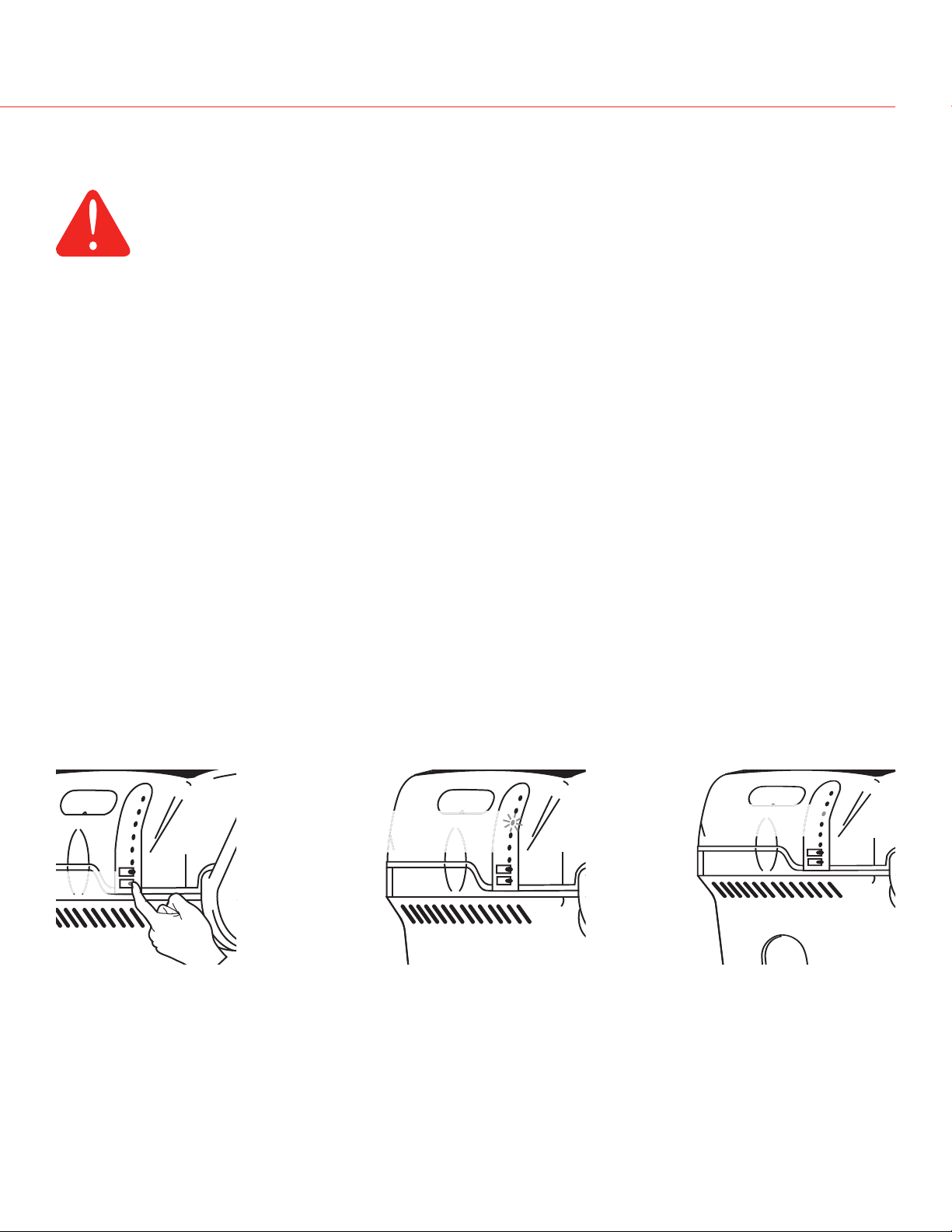
• Test the drain by pressing the EMPTY button until the Clean Tank light begins blinking,
indicating a drain cycle has begun.
NOTE: It may take approximately 10 minutes for the tank to fully flush and drain. TO BYPASS
AND DRAIN IMMEDIATELY, Press and hold the EMPTY button again while the Clean Tank light
is blinking. This will bypass the flush and immediately drain the tank. TO STOP draining, press
the Reset button.
• Mount the provided yellow tank service sticker on the duct/wall near the unit. Ensure the
drain hose is secured to prevent inadvertent disconnection. Check that the hose is plumbed
to a drain/condensate to prevent water spurting.
69-2036EFS—07
Page 4

Installation Guide
InsTallaTIon ReCommendaTIons
Setting Homeowner Expectations for the TrueSTEAM Experience:
It may take up to a week of continuous operation to achieve the humidity set point, depending
on weather, size of home, furnishings in the home, insulation, etc.
If using a six (6) gallon unit, the most appropriate setpoint is 30-35% or until there is condensation on the windows, then lower the setpoint (if not in frost protection mode). If the home can’t
achieve the setpoint, the unit may be under-sized (if home is under 2000 sq ft, this can also be
due to insulation, windows, arid climate, etc.) or the outdoor temperature may be too low to
maintain adequate humidity levels. Honeywell recommends waiting for the temperature to moderate closer to 20°F (-6°C).
If this occurs and the selected humidity levels are not achieved, then a larger capacity model
may be needed.
For the first week of operation, it is normal to experience a slight plastic odor in the home,
depending on the amount of supplied ventilation. If the remote hose is used, there may be a
slight rubber odor. These odors will dissipate within days of installation.
If the homeowner sees that TrueSTEAM is not humidifying but there is a call for humidity, it is
likely the unit is operating in drain cycle mode. Ask the homeowner to check again in an hour if
they are concerned the device may not be operating.
If the Call Service light is blinking, instruct the homeowner to press and hold the Reset button to
clear the fault. If the fault doesn’t clear, unplug the power to TrueSTEAM and plug back in to the
electrical outlet. Wait 24 hours prior to calling a contractor. The call service light may be blinking
due to a low voltage condition in the area and will reset to operate correctly when full power is
restored.
There may be a slight increase in the homeowner’s energy consumption. However, when operating correctly, TrueSTEAM will make the home feel warmer, allowing the homeowner to lower the
temperature setting on the thermostat. Every degree lower on the thermostat can save up to 3%
on heating costs.
69-2036EFS—07 2
Page 5
TrueSTEAM Humidification System
WhaT you WIll need To InsTall TRuesTeam
Tools/Hardware needed:
• Wire stripper/cutter
• Drill or duct-cutting tool
• 1-3/4-in. hole saw
• 1/8-in. drill bit
• Phillips and slotted (or Torx) screwdriver
• 18-gauge thermostat wire (5 or 2 conductor)
Material Provided:
• 1/4-in. copper or plastic water line
• 1/2-in. drain hose and clamps
• Mounting bracket and hardware
• In-line water filter* (50028044-001)
• Saddle valve
• Back-flow valve (50030142-001)
Options:
• Remote Installation Kits
– 10-foot hose and nozzle kit (50024917-001)
– 20-foot hose and nozzle kit (50024917-002)
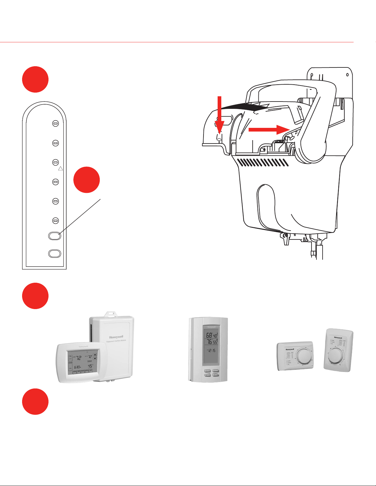
• Humidity Controls
– Manual Humidistat (H8908ASPST)
– TrueIAQ (DG115EZIAQ)
– VisionPRO IAQ (YTH9421C1010)
• Water line T-fitting
• Manual shut-off valve
• Remote hose P-trap
• Remote mount duct board adapter kit
(32005530-001)
• Differential pressure switch (50027910-001)
* Warranty requires in-line water filter installation with regular service.
3 69-2036EFS—07
Page 6
Installation Guide
safeTy PReCauTIons
CAUTION: Voltage Hazard.
Can cause electrical shock or equipment damage.
Disconnect HVAC equipment before beginning installation.
Safety Precautions
• Do not direct the steam nozzle at people.
• If used near a pool or spa, ensure the TrueSTEAM can not fall into the water or be splashed.
Also, ensure the TrueSTEAM is plugged into a GFI ground fault interrupt outlet.
• Water inside tank can be very hot. Follow installation instructions and service steps exactly
as given in the technical literature.
Warning: Electrocution, Heavy Equipment, and Chemical Hazard.
Can cause death, blindness, water damage to home and heating element failure.
• Do not cut into any air conditioning or electrical line
• Wear safety glasses when cutting or drilling.
• Mount the humidifier in a level position to avoid water damage or heating element failure.
• Reinforce duct as necessary to ensure stability.
The preferred installation location is on the warm or supply side of the furnace. If that location is
not possible, the steam nozzle should be inserted a minimum of 12 in. upstream of the furnace filter.
Depending on the location and the duct rigidity, additional duct reinforcement may be necessary.
Warning: Steam Condensation, Fire, and Freezing Water Hazard.
Can cause failure of fan or limit control or result in water damage to home.
• Do not install the humidifier where the ambient temperature is lower than 32°F (0°C) or higher
than 120°F (49°C).
• Do not install the humidifier through sidewalls of a return air duct made of wood (e.g., floor
joist).
• The mounting area must be strong enough to support the humidifier’s weight when it is full
of water (approximately 12 to 15 lbs.), and to hold the humidifier in a level position for safe,
reliable operation. Otherwise, additional duct or wall reinforcement will be necessary.
• If the ducting has exposed insulated materials on the interior, ensure the nozzle extends
beyond the insulation by clearing away excess insulation at the insertion point. You may wish
to replace a section of insulated duct (approximately 6 in. x 6 in.) with rigid, non-insulated
sheet metal to ensure effective installation.
• Mount the unit where it will have smooth air flow across the end of the steam nozzle.
• Allow at least 1 foot clearance to ventilation holes in humidifier’s cover. Do not cover these
holes. Covering them can increase the internal operating temperature of the humidifier and
shorten the humidifier’s life.
• Allow at least 4 inches of clearance between the steam nozzle insertion hole and the top of
the interior duct to avoid condensation forming. The mounting template is designed to allow
clearance if the top of the template is at or below the top surface of the interior duct.
• Do not mount directly to duct board. Remote mount nozzle attachment allowed only when
using with a duct board adapter kit (part #32005530-001).
• Do not install in completely enclosed spaces, such as a cabinet or unventilated closet.
Choose a location that is well ventilated.
69-2036EFS—07
Page 7
TrueSTEAM Humidification System
M24744
M24745
M24746
M24894
If installing the humidifier directly to the supply duct, follow steps on pages 5–6 and 13–18.
If mounting remote from the duct, follow steps on pages 7–18.
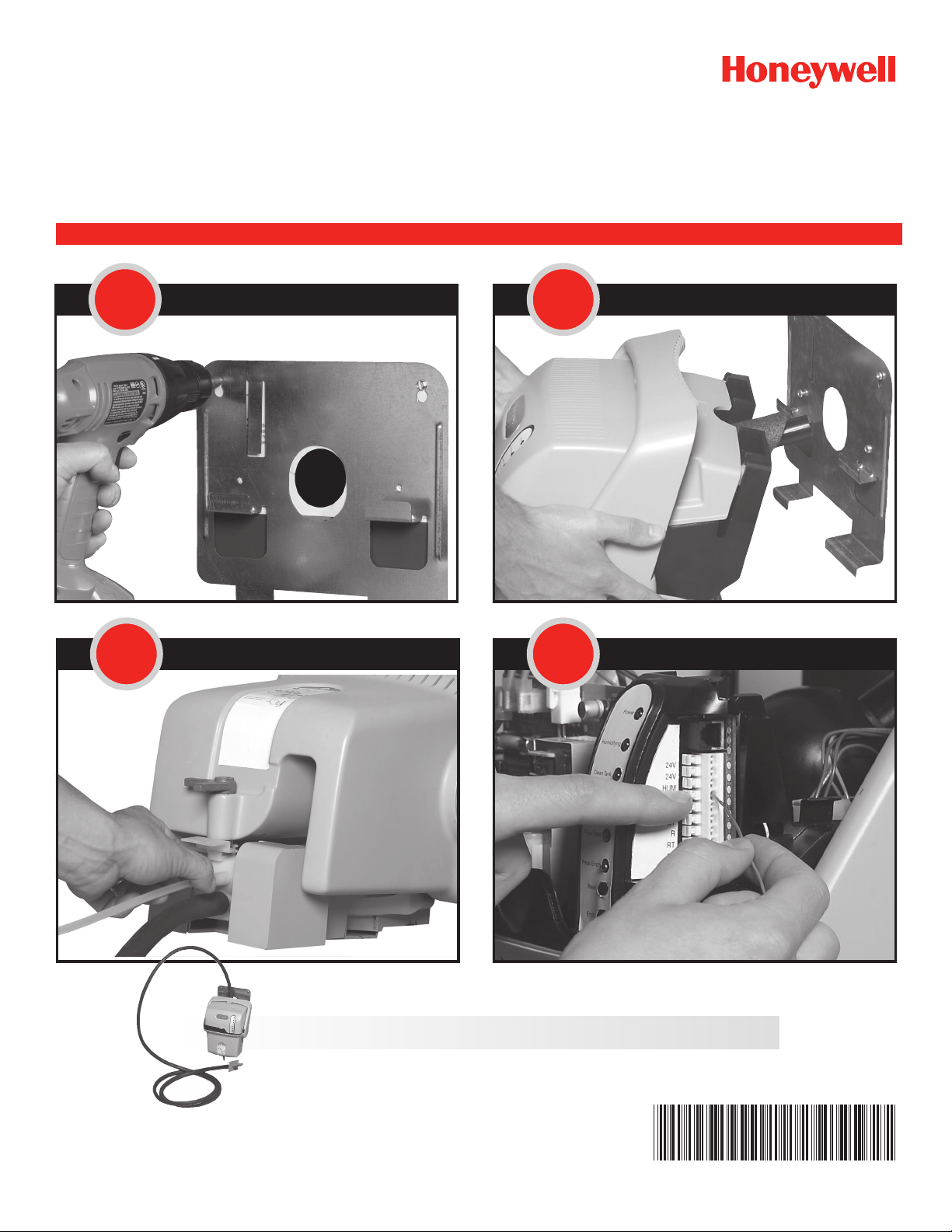
duCT mounT InsTallaTIon
Choose a location that has access to a:
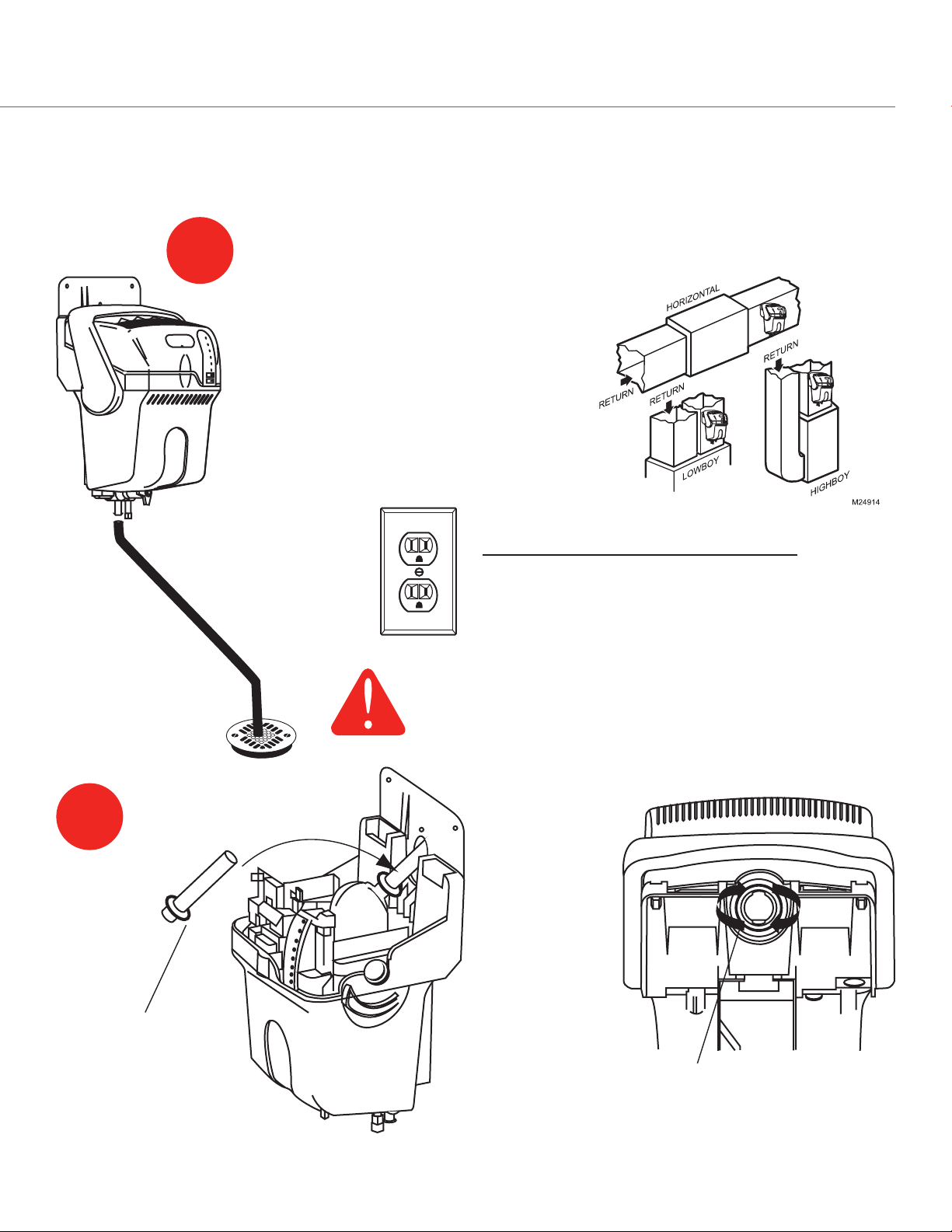
1
Draining water
may be hot.
Ensure drain outlet not exposed.
• Drain allowing a slope of 1/4 in.
per foot of drain hose.
• Cold water line.
• Electrical circuit rated to your
humidifier.
• Vertical surface with adequate
clearances.
Continuous
downslope
Required Minimum
Model
Circuit Capacity
HM506 7 Amps
HM509 10 Amps
HM512 12 Amps
CAUTION
Hot water temperature above 120°F (49°C)
can cause burns from scalding.
2
Install duct nozzle.
Ensure o-ring gasket
is properly seated in
the groove.
Insert nozzle and twist clockwise to ensure tight seal of
nozzle to TrueSTEAM.
69-2036EFS—07
Page 8
Installation Guide
M24749
M24750
M24748
SUPPLY
12 INCHES
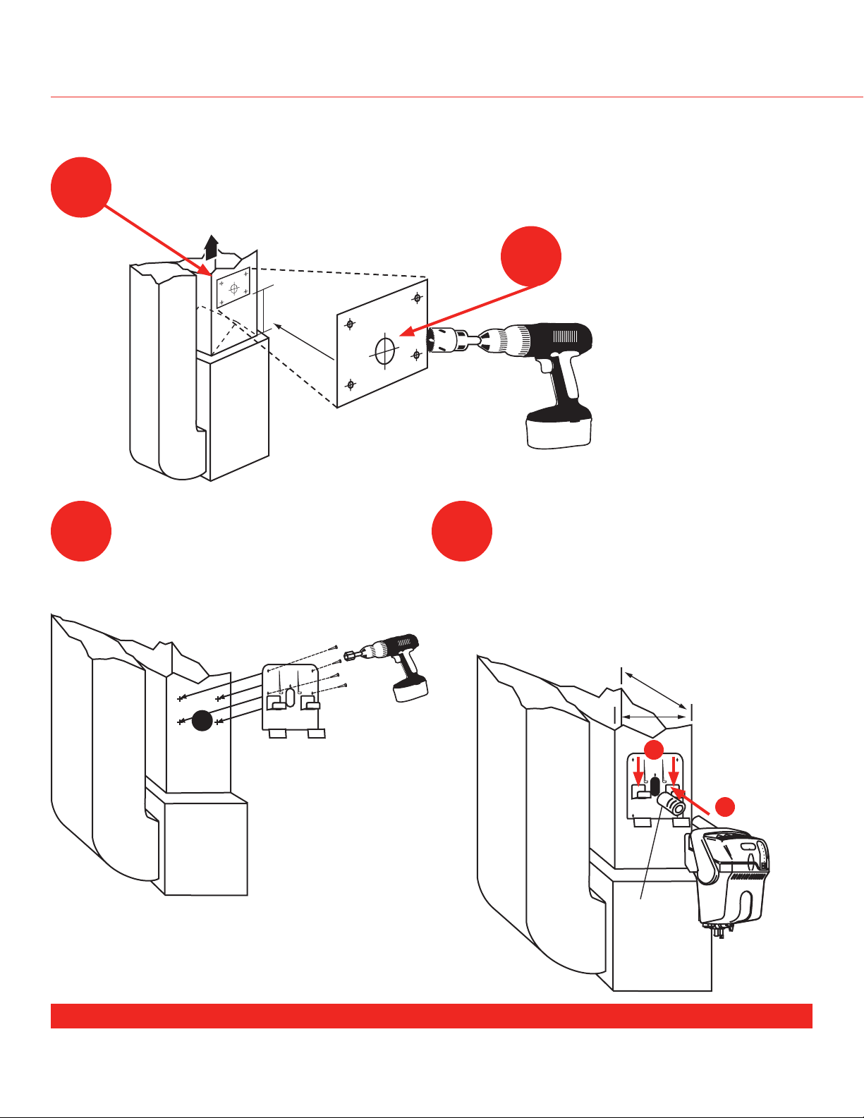
duCT mounT InsTallaTIon
Position template sticker on supply duct. For tall coils that do not have this
3
clearance available, refer to remote mounting instructions.
Secure bracket to duct using #8
5 6
self-drilling sheet metal screws (4).
4
Drill 1-3/4-in. hole.
A) Slide foam gasket over nozzle and
insert the nozzle into duct hole
(pictured).
B) Push down to secure humidifier to
bracket arms. Ensure gasket forms
tight seal in duct hole.
Allow 3 in. clearance from nozzle
outlet to duct wall.
Proceed to page 13 for plumbing and wiring instructions.
69-2036EFS—07 6
B
A
Foam
gasket
Page 9
M24896A
RemoTe mounT InsTallaTIon
Use for mounting to a location other than the supply duct.
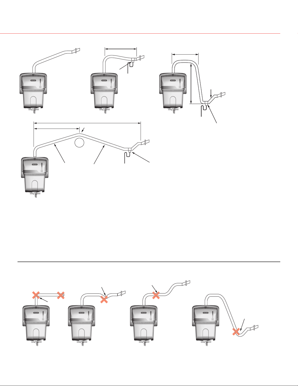
TrueSTEAM Humidification System
Most operation problems are caused
by improper hose installation. Always
ensure an uphill flow when installing
the remote hose, and avoid kinks,
sharp turns, or low spots that could
restrict the flow of steam into the
injection nozzle or condensation back
into the humidifier.
If the remote hose cannot be installed
with an upward pitch of 2 in./ft., a
wetted drip tee must be installed.
Failure to do so can result in back
pressure on TrueSTEAM, which can
lead to duct nozzle water spitting or
leaking gasket. Remote hose must be
supported to prevent sagging or low
spots.
When remote mounting, also follow these critical
steps in sizing the proper TrueSTEAM:
If the steam distribution tube is going into an unconditioned air space (e.g., attic), insulate the tube to
ensure steam output efficiency:
• Honeywell recommends self-seal pipe insulation
for hot and cold water pipes. Insul-Tube 1-1/8 in. ID
x 1/2 in. wall 25/50 Factory Mutual 062411, flame
retardant added.
The 6-gallon model (HM506) can be remotely mounted up to:
• 5 feet without insulating the steam distribution tube
• 15 feet if insulating the steam distribution tube
The 9- and 12-gallon models (HM509 and HM512)
can be remotely mount up to 20 feet with or without
insulating the steam distribution tube.
Ensure at least 2 in. per foot slope if installing the
remote hose horizontally.
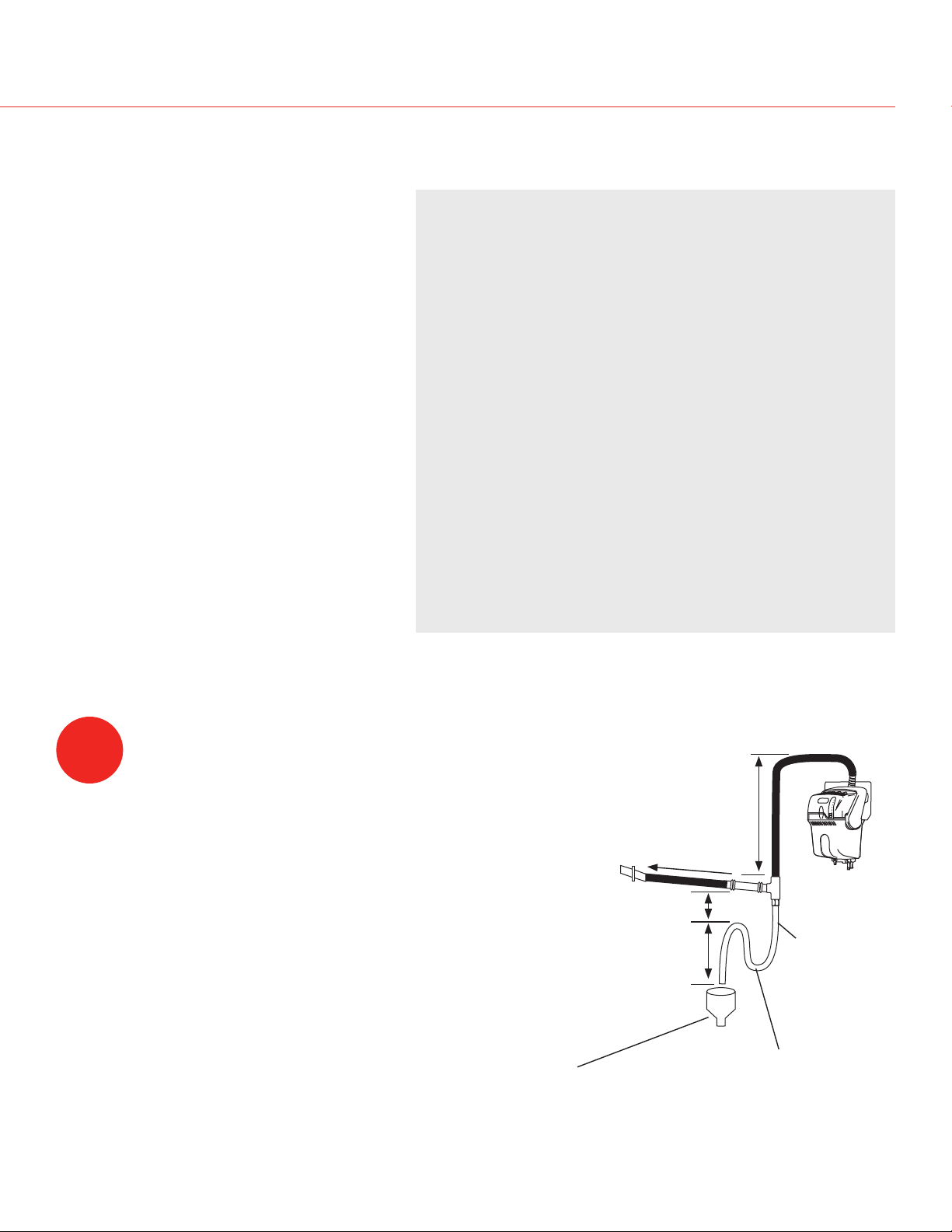
1
Choose a location for TrueSTEAM and the
remote duct nozzle (see remote installs on
pages 6–7).
It should have access for:
• Remote hose installation. Steam hose
must be installed with 2 in./ft. pitch on a
continuous uphill slope.
• Drain. Allow a continuous downslope to the
drain.
• Cold water line.
• Electrical circuit rated to your humidifier
(see circuit ratings on page 10).
Funnel or floor drain. Refer to governing
codes for drain pipe size and maximum
temperature requirements.
Maximum 3 ft.
2 in./ft. uphill
6 in.
8 in.
1/2 in.
minimum
diameter
Water in
elbow
7 69-2036EFS—07
Page 10
Installation Guide
M24786
M24781
M24785
M24936
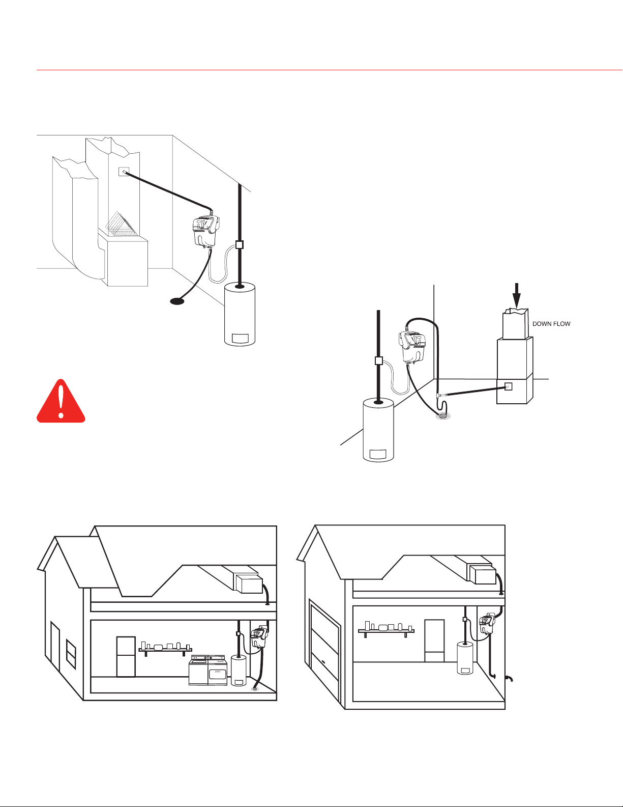
PRoPeR hose InsTalls
Furnace or Mechanical Room Remote
Note: If air handler location temperatures will drop
below freezing at any time, TrueSTEAM must be
mounted in a conditioned space, running a remote
hose to the duct.
Duct Mount Remote
CAUTION
Hot water temperature above 120°F (49°C)
can cause burns from scalding.
Living Area Remote Options
Garage Remote
Draining
water may
be hot.
Ensure
drain outlet not
exposed.
69-2036EFS—07
Page 11
2 IN. PER FT
2 IN. PER FT
2 IN. PER FT
2 IN. PER FT
20 FT MAX
P - TRAP
DRAIN
WITH TRAP
5 FT MAX
3 FT MAXIMUM
DRAIN
P - TRAP
IF NO SLOPE
10 FT MAX
GENTLE BEND
OBSTRUCTION
SUPPORTED REMOTE HOSE
20 FT MAX
DRAIN
WETTED P - TRAP
NOTE: HEIGHT OF TRAP MUST BE GREATER
THAN THE DUCT STATIC PRESSURE
DRAIN
P - TRAP
IF NO SLOPE
TYPICAL INSTALLATION
WHEN TrueSTEAM IS ABOVE
REMOTE NOZZLE
KINKED
SAG
NO SLOPE
NO SLOPE
M24915A
UNDRAINED
ELBOW
TrueSTEAM Humidification System
PRoPeR hose InsTalls
NOTES:
• Slope hose up in direction of steam flow at 2 in. per foot;
• Maximum length of remote steam hose is 20 ft.
• Slope hose down in direction of steam flow at 3/4 in. per foot;
• Height of P-traps must be greater than the duct static pressure. (Typical
3 in. will suffice.) P-trap must also be wetted (see page 7).
• Minimize sharp bends and elbows.
• Insulating the remote hose in unconditioned spaces will sustain
efficiency better than not insulating the hose.
AVOID THESE INSTALLATION MISTAKES.
9 69-2036EFS—07
Page 12
Installation Guide
M24744
M24745
M24764
M24765
M24894
RemoTe mounT InsTallaTIon
Model Minimum Circuit Capacity
HM506 7 Amps
HM509 10 Amps
HM512 12 Amps
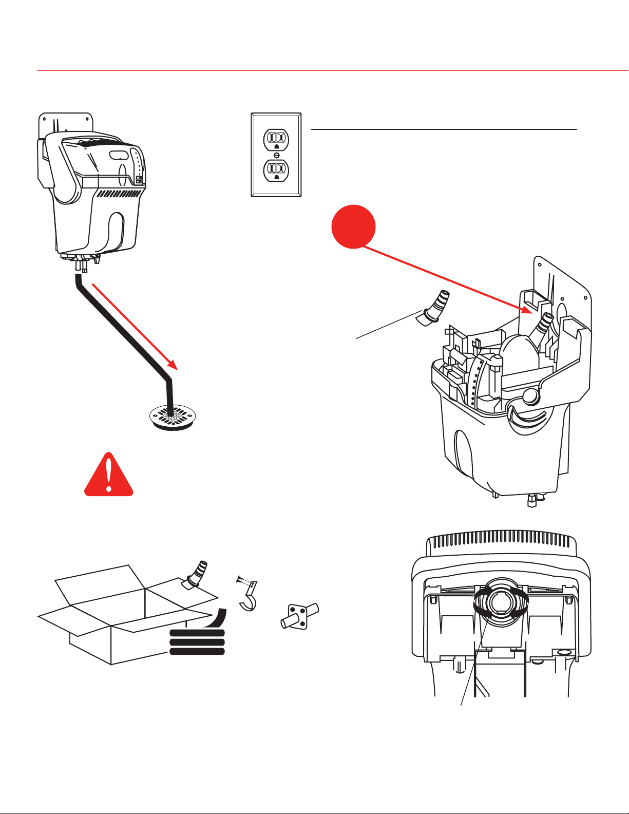
Install hose adapter from Remote
2
Mount Kit.
Draining water
may be hot.
Ensure drain outlet not exposed.
Remote Mount Kit
(sold separately)
Ensure o-ring gasket is
properly seated in the
Continuous
groove.
downflow
CAUTION
Hot water temperature above 120°F (49°C)
can cause burns from scalding.
Hose Adapter
Hose Clamps
Duct Nozzle
Remote Hose
• 50024917-001 = Ten Foot Hose Kit
• 50024917-002 = Twenty Foot Hose Kit
69-2036EFS—07 0
Insert hose adapter and twist
clockwise to ensure tight seal
of nozzle to TrueSTEAM.
Page 13
M24766
3
M24767A
M24768
TrueSTEAM Humidification System
RemoTe mounT InsTallaTIonRemoTe mounT InsTallaTIon
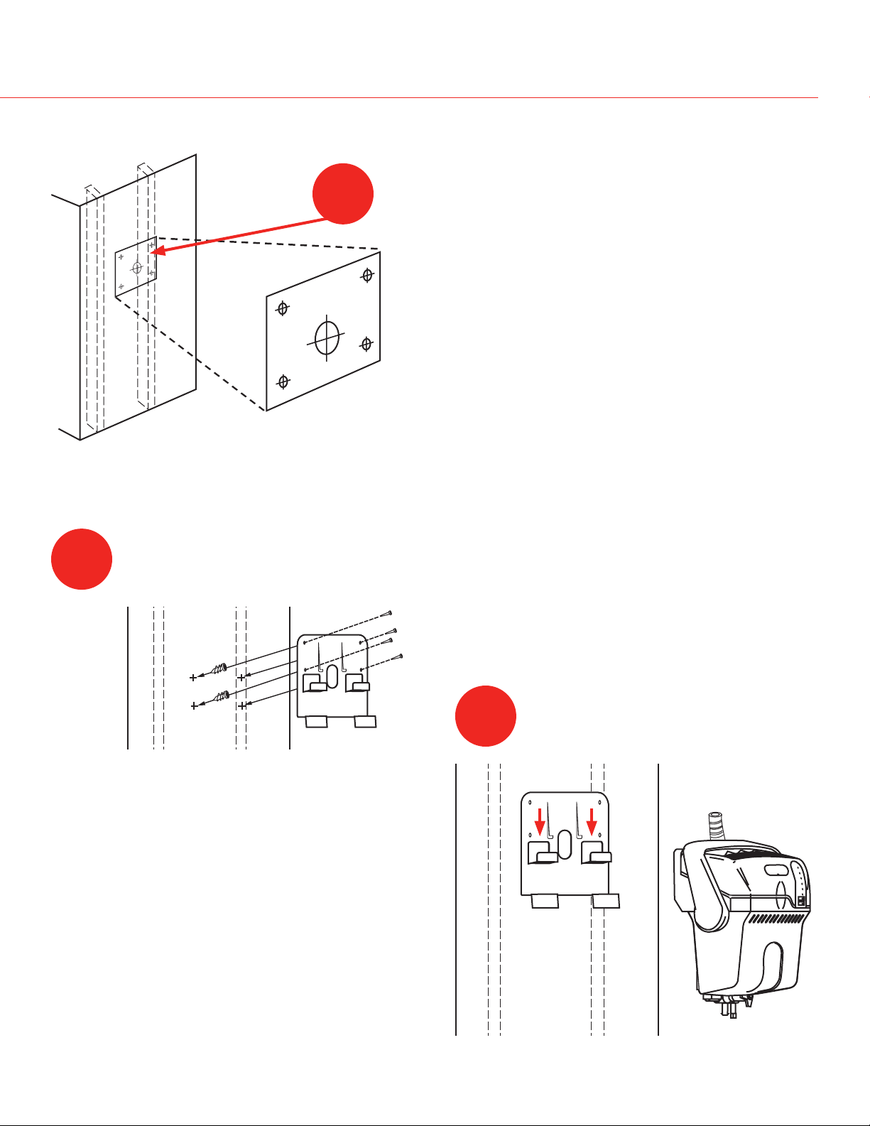
Position template sticker on remote location.
Note: TrueSTEAM will weigh 12–15 lbs. (+/- 2 lbs.) with
water, so if mounting onto drywall or plaster, position
one side over a wall stud.
4
Insert wall anchors (4) into pilot holes and secure
bracket to location.
5
Push down to secure TrueSTEAM to
bracket arms.
69-2036EFS—07
Page 14
Installation Guide
M24770
M24771
RemoTe mounT InsTallaTIon
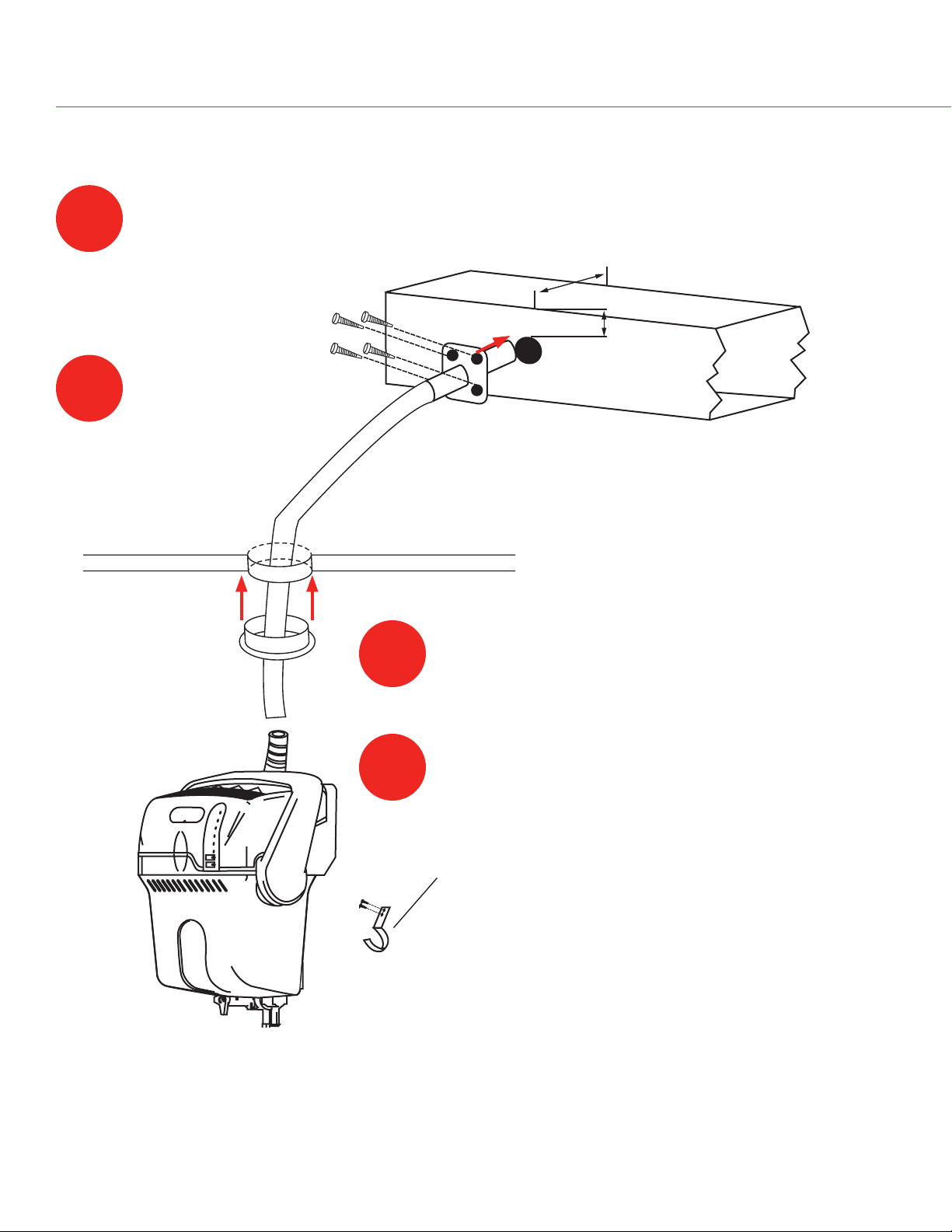
Cut a 1-3/4 in. diameter duct hole, install the provided
gasket, and slide the remote nozzle up into the duct.
6
7
Secure remote nozzle to duct using #8 self-drilling
sheet metal screws (4).
Run remote hose from
the humidifier to the duct
nozzle location. Up to 20
ft. of hose can be used.
Minimum 3 in. clearance
required from nozzle outlet to
duct wall.
8
9
If mounting remotely requires running
hose through structural barriers (ie.
wall or ceiling), cut at least a 1-3/4 in.
hole and slide hose through.
Seal off unconditioned space with a
grommet (not provided) or caulk.
Attach remote hose by sliding over the nozzle
and adapter. Secure both hose ends with
clamps (provided).
IMPORTANT:
Run hose continuously uphill. For horizontal runs,
ensure a slope of 2 in. uphill per foot. Secure hose
every horizontal foot using clamps (provided).
For long horizontal runs, support the hose by first
securing a length of 2 x 4 lumber, U-channel, or
angle iron with the appropriate slope. Then attach
the hose to the top of this support. If remote hose
requires downward pitch, refer to pages 5 and 7 for
instruction.
69-2036EFS—07 2
Page 15
M24852
M24772
10
M27428
TrueSTEAM Humidification System
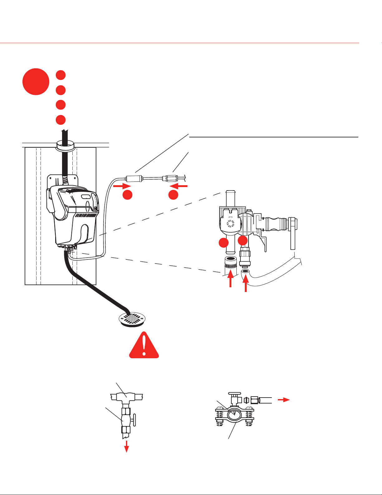
PlumbIng
A
Insert 1/4-in. water line into filter. Apply modest pressure to ensure a tight fit.
B
Insert 1/4-in. water line into back-flow valve. Apply modest pressure for a tight fit.
C
Connect 1/2-in. drain tube. Secure drain tube to barbed fitting with hose clamp.
D
Shut off the water supply. Secure 1/4-in. copper or plastic water feed tube.
Description Part Number
In-Line Water Filter (included)
(required for warranty)
Back-flow valve (included)
(required)
To water supply
50028044-001
50030142-001
A
B
1/4-in. copper
or plastic
Enlarged view
Continuous
downslope
1/2-in.
drain tube
D
C
1/4-in. water line
Draining water may be
hot. Ensure drain outlet
not exposed. Ensure
drain or condensate
pump is rated for at
least 120°F water.
CAUTION
Hot water temperature above 120°F (49°C)
can cause burns from scalding.
Water line tapping options. See instructions provided with the option you choose.
Manual shutoff
valve (sold
separately)
To humidifier
T-fitting
Piercing pin
Water supply line
Saddle valve (provided)
To humidifier
Check all water line connections to ensure no leaks once TrueSTEAM is operational.
3 69-2036EFS—07
Page 16
Installation Guide
M24754
M24895
24V
24V
HUM
HUM
C
GT
R
RT
GF
EXT
M24893
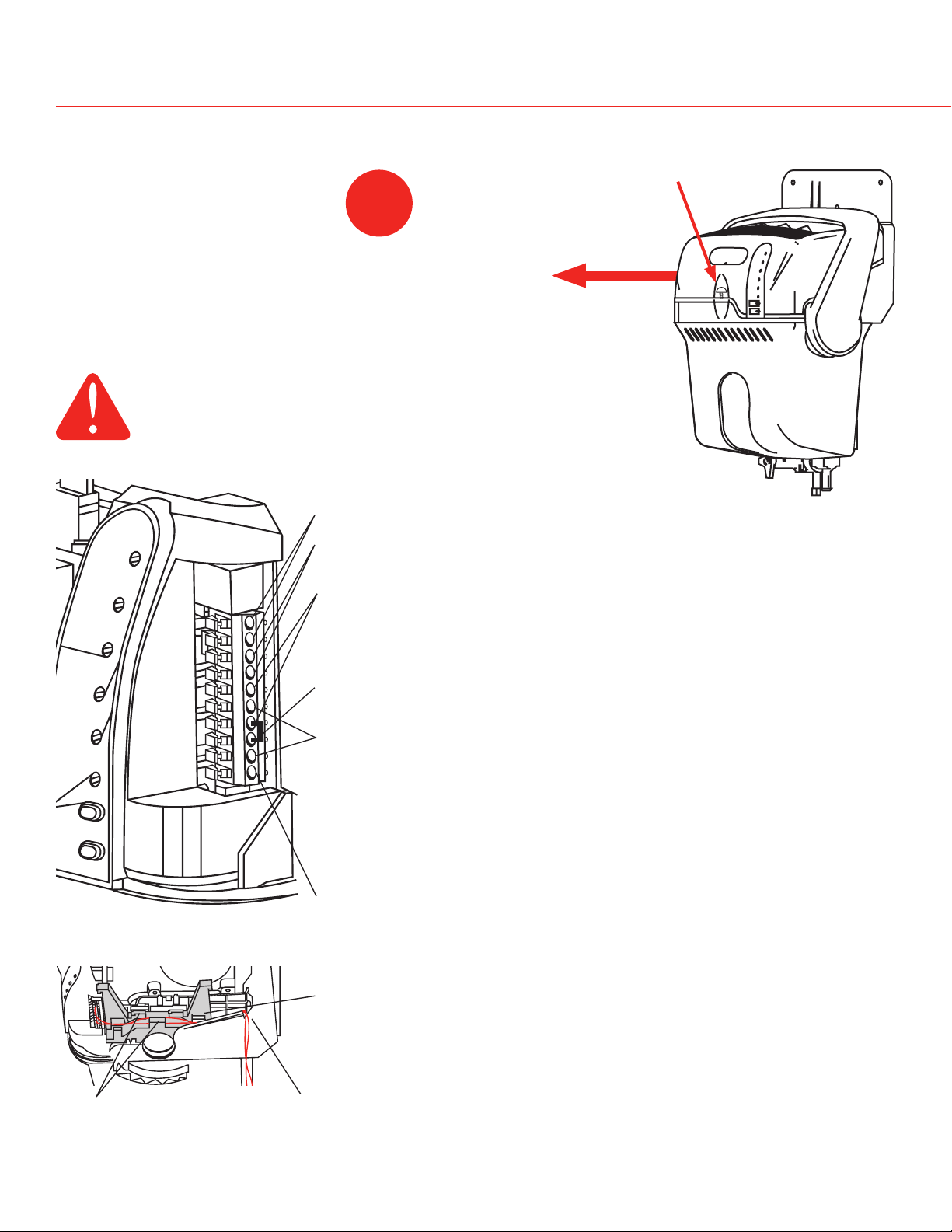
WIRIng
CAUTION: Voltage Hazard.
Before wiring to HVAC terminals, disconnect HVAC
equipment power. Ensure humidifier is not plugged in.
Loosen captive cover
11
screw. Slide cover out from
front.
Low-Voltage Terminals
24V AC power for electronic humidistat.
HUM Low-voltage humidistat (or thermostat) terminals control
C, R Connects to HVAC system transformer terminals (or relay
RT Connects to thermostat R terminal, which is normally
GT, GT connects to thermostat G terminal. GF connects to
GF
EXT When a 24-vac fan board is not used to control blower
Tabs Notch
Route wires through the raised harness tabs and out the notch at
the rear of the chassis. Ensure wires are secure and do not interfere with assembly of cover.
humidifier operation.
transformer fan control R and C) to ensure HVAC power
is present before humidifying. This can be disabled by
changing DIP switch 4 (see page 16).
switched to call for fan.
fan board G terminal. Thermostat G passes through the
normally-closed (NC) relay contacts to GF, allowing fan
activation. When TrueSTEAM is ready to provide humidity
to the home, it will take control of the fan by forcing power
from RT to GF (if not already activated).
(hydronic or cooling-only applications), this connection
with GF provides dry-contact closure for fan calls. EXT/
GF may be wired to a low-voltage relay control center to
provide line-voltage fan control.
69-2036EFS—07
Page 17
HVAC
RECOMMENDED
AIR FLOW SWITCH (AFS)
MECHANICAL
HUMIDISTAT
HVAC
POWER
MASTER
THERMOSTAT
HUM
HUM
GYWR Rc
GYWRC
TrueSTEAM - INTERNAL
24V
24V
HUM
HUM
C
GT
R
RT
GF
EXT
M24756
12
FAN
FURNACE BOARD
EQUIPMENT INTERFACE MODULE (EIM)
G
C
24V
24V
HUM
HUM
C
GT
R
RT
GF
EXT
CONV. HP
1
2
3
C
R
RC
RH
W1
W2
W3
Y
Y2
G
O/B
AUX
AUX2
Y
Y2
G
H1
U
M2
D1
H
M2
V1
N
T2
HEAT 1 RELAY
HEAT 2 RELAY
HEAT 3 RELAY
COOL 1 RELAY
COOL 2 RELAY
FAN RELAY
VISIONPRO IAQ
D-1
R-2
C-3
M24758
RECOMMENDED AIR FLOW SWITCH (AFS)
TrueSTEAM - INTERNAL
HVAC
TrueIAQ
THERMOSTAT
HUM
HUM
R
C
GYWR Rc
GYWR C
24V
24V
HUM
HUM
C
GT
R
RT
GF
EXT
RECOMMENDED
AIR FLOW
SWITCH (AFS)
M27409
HVAC
POWER
MASTER
TrueSTEAM - INTERNAL
TrueSTEAM Humidification System
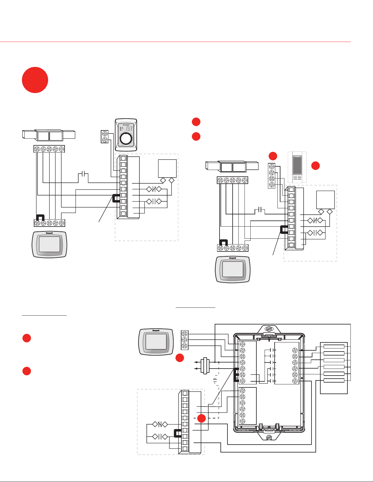
WIRIng
Wire the TrueSTEAM according to the diagram that applies to your humidity control.
Follow this diagram if using a mechanical humidistat
such as H8908ASPST or other.
Factory
installed
jumper
If AFS is used, ensure DIP 5
is in ON position.
Follow this diagram to wire TrueIAQ for manual
operation.
A
Set TrueIAQ ISU parameter 10 to 1, and ISU 25 to 2.
For auto-operation: also wire W and G to thermostat
B
W and G.
B
A
Factory
installed
jumper
Follow this diagram if using VisionPRO IAQTM for independent fan control. TrueSTEAM will
independently activate furnace fan (humidity on demand).
Set VisionPRO IAQTM ISU
A
parameter 374 to 3.
If operating TrueSTEAM without
B
monitoring HVAC power or
AFS, C wiring hookup is
optional, but ensure DIP 4 is in
ON position.
If AFS is used, ensure DIP 5
is in ON position.
69-2036EFS—07
A
If AFS is used, ensure DIP 5 is in ON position.
B
Page 18
Installation Guide
FAN
FURNACE BOARD
EQUIPMENT INTERFACE MODULE (EIM)
G
C
24V
24V
HUM
HUM
C
GT
R
RT
GF
EXT
CONV. HP
1
2
3
C
R
RC
RH
W1
W2
W3
Y
Y2
G
O/B
AUX
AUX2
Y
Y2
G
H1
U
M2
D1
H
M2
V1
N
T2
HEAT 1 RELAY
HEAT 2 RELAY
HEAT 3 RELAY
COOL 1 RELAY
COOL 2 RELAY
FAN RELAY
HVAC
POWER
MASTER
VISIONPRO IAQ
D-1
R-2
C-3
M24761
RECOMMENDED
AIR FLOW SWITCH
(AFS)
TrueSTEAM - INTERNAL
24V
24V
HUM
HUM
C
GT
R
RT
GF
EXT
HUMIDISTAT
HUM
HUM
HAC
HAC
MECHANICAL
HUMIDISTAT
HUM
HUM
HAC
HAC
RECOMMENDED
AIR FLOW SWITCH
(AFS)
TrueSTEAM - INTERNAL
HVAC
120 VAC
R8222
RED
BLACK
L1
L2
120
VAC
AT120
R C
M24760
HVAC POWER MASTER
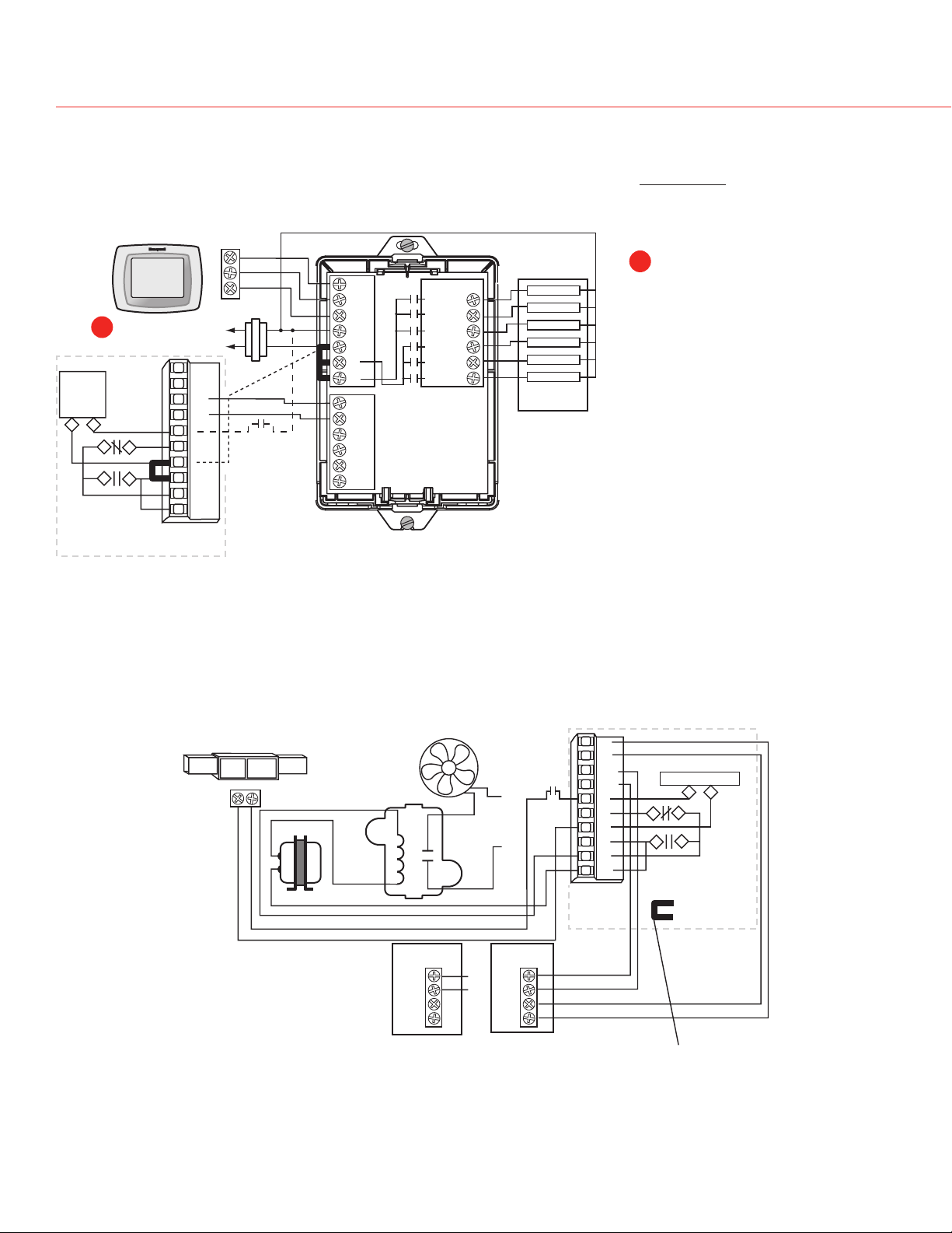
WIRIng
Follow this diagram for a system with the VisionPRO IAQTM with operation dependent on HVAC power
(humidification and fan call by thermostat).
Set VisionPRO IAQTM ISU
B
parameter 374 to 1. This
allows the thermostat to call
B
for fan at the same time as it
calls for humidification.
If AFS is not used, set DIP 4
ON and wire HUM terminals
only.
If AFS is used, set DIP 5 ON
and DIP 4 OFF and wire R, C,
and Hum terminals.
Follow this diagram if using a blower fan dedicated to the TrueSTEAM (a fan separate from the HVAC
equipment, as in hydronic or cooling-only applications).
69-2036EFS—07 6
If AFS is used, ensure DIP 5
is in ON position.
Remove Factory installed
jumper (R/RT)
Page 19
13
POWER
HUMIDIFYING
CLEAN TANK
CALL SERVICE
PRESS RESET
PRESS EMPTY
RESET
EMPTY
SEE LABEL BELOW
!
M24763
M24762
TrueSTEAM Humidification System
Slide the cover back into place and secure captive screw.
Turn on the water supply and plug in the humidifier.
The Press Reset light will blink when
14
power is applied.
Press/release the RESET button to
ready the TrueSTEAM. If not pushed,
TrueSTEAM will automatically move to
ready after five minutes.
WIRIngWIRIng
Turn the humidity control to the “Test” position. If the “Test” position is unavailable,
15
turn the control to a high setpoint (60% +). Be sure to turn this back down (or off) when
testing is complete. “Off” will turn TrueSTEAM off.
Confirm that the furnace blower turns on to circulate air. This will take about 10–15
16
minutes upon call for humidity.
Important for Remote Installation:
After TrueSTEAM has produced steam for 10–15 minutes, check the integrity of the
remote hose to ensure no sags have occurred. Add or adjust clamps if necessary to
ensure 2 in. per foot continuous slope.
7 69-2036EFS—07
Page 20
Installation Guide
M24853
OFF
ON
OFF
ON
OFF
ON
DIP 1
DIP 2
DIP 3
DIP 4
DIP 5
DIP 6
DIP 1
DIP 2
DIP 3
DIP 4
DIP 5
DIP 6
DIP 1
DIP 2
DIP 3
DIP 4
DIP 5
DIP 6
DIP
3
DIP
3
D
IP
3
D
IP
6
D
IP
6
DIP
6
M28181
DIP 1
DIP 2
DIP 3
DIP 4
DIP 5
DIP 6
DIP 1
DIP 2
DIP 3
DIP 4
DIP 5
DIP 6
OFF
ON
OFF
ON
DIP 1
DIP 2
DIP 3
DIP 4
DIP 5
DIP 6
OFF
ON
DIP
3
D
IP
3
DIP
3
D
IP
6
DIP
6
D
IP
6
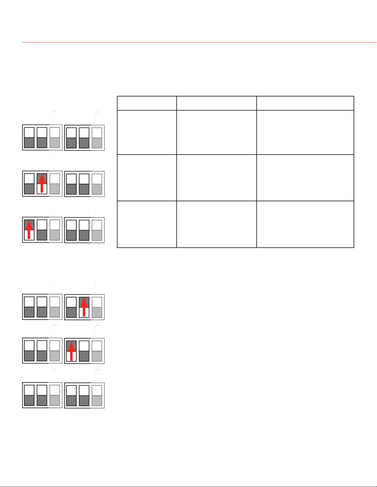
dIP sWITCh seleCTIon
Between the transformer and LED display on the circuit board are two sets of DIP switches. DIP
1 and 2 can be configured to adjust cleaning cycles. DIP 4 and 5 can simplify wiring. DIP 3 and 6
are not used at this time. Details below.
Run time (hrs) End-of-Season timer
(hrs)
10 hrs of humidifying before system
auto-flushes debris
48 hrs before system autodrains and remains empty
until next call for humidity.
from tank.
20 hrs of humidifying before system
auto-flushes debris
48 hrs before system autodrains and remains empty
until next call for humidity.
from tank.
30 hrs of humidifying before system
auto-flushes debris
48 hrs before system autodrains and remains empty
until next call for humidity.
from tank.
Clean tank indicator
1 year of total time (operational
and inactive) before the Press
Empty light will blink, indicating
it is time to manually clean the
water tank.
1 year of total time (operational
and inactive) before the Press
Empty light will blink, indicating
it is time to manually clean the
water tank.
1 year of total time (operational
and inactive) before the Press
Empty light will blink, indicating
it is time to manually clean the
water tank.
DIP 4 OFF, DIP 5 ON: If TrueSTEAM determines that no airflow*
is present two minutes after the blower fan call, it will shut down
steam output and activate a service light.
*Requires installation of air flow switch. See 'Wiring' section for details.
69-2036EFS—07
DIP 4 ON, DIP 5 either setting: TrueSTEAM will allow humidity
without HVAC power present and without airflow.
DIP 4 OFF, DIP 5 OFF: TrueSTEAM will not be allowed to humidify
without HVAC power being present.
Page 21
TrueSTEAM Humidification System
M24901
TRoubleshooTIng
TrueSTEAM has internal system diagnostics that monitor system operation, maintenance schedules,
and faults. If a system fault is detected, the system will attempt to recover itself up to five times in a
24 hour period. If unable to recover in that time, the red Call Service LED light will activate.
If the TrueSTEAM Call Service light is red, a system fault has occurred from which the humidifier can not recover by itself. The table below shows the possible faults, along with steps to fix
TrueSTEAM.
If the red Call Service LED light is on, press/release the RESET button. The red Call Service LED
light will begin blinking in a series that indicates what fault occurred. Refer to the table below
for the fault signified by the number of blinks that occur. To clear the fault, press and hold the
RESET button for 5 seconds.
Press/hold the EMPTY button to clear the Service Timer light (i.e. the Press Empty button).
Press/release the EMPTY button to drain the tank.
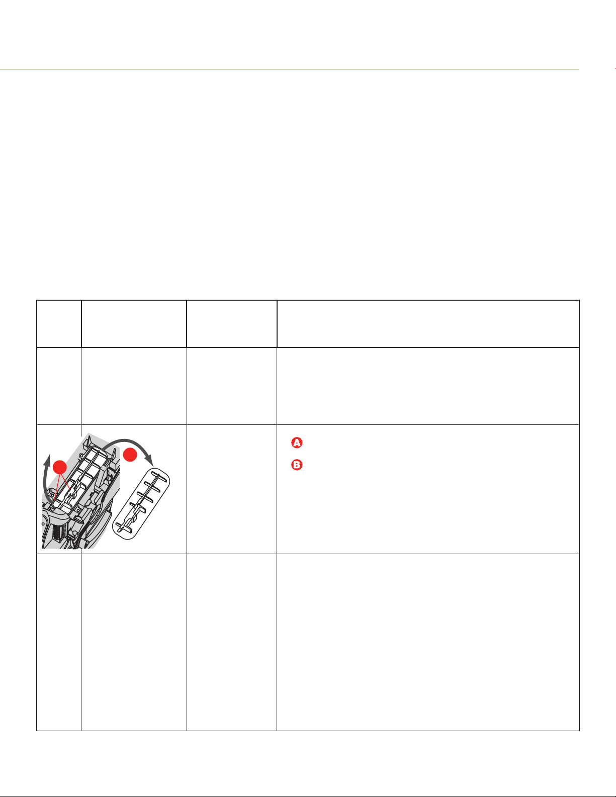
No. of
Red
Light
Blinks
1 Water/Heater temper-
2 Water sensors failed. Yes, system will
3 Failure to fill tank
Fault Description Auto-
ature sensor failed.
B
A
with water.
Recoverable?
Yes, system will
return to “Ready”
if fault no longer
exists in 1 hour.
return to “Ready”
if fault no longer
exists in 1 hour.
Will attempt to
reset itself 5 times
in 24 hours.
Yes, system will
return to “Ready”
if fault no longer
exists in 1 hour.
Steps to Fix
To be Performed by Professional HVAC Technician Only
• Unplug TrueSTEAM and remove cover.
• Check water sensor connection to electronic board.
• Reattach cover and plug TrueSTEAM in.
• If fault reappears, follow the cleaning steps on pages 23–24.
• Reassemble tank and press the RESET button.
• If fault returns, replace with applicable wattage heating
element.
• Unplug TrueSTEAM and remove cover.
• Disconnect water level sensor wiring, remove screen and
lift snap-hinge clamp.
Remove water sensor assembly.
• Clean water sensor probes using warm soapy water so that
the metal is exposed.
• Reassemble the sensor assembly in the unit, reattach and
secure cover.
• Plug unit back in and press the RESET button.
• If fault reappears, replace sensor assembly.
• Ensure inlet water is on.
• Check for leaks around the tank seal and solenoid.
• Turn off water supply and replace in-line water filter.
• Press/hold RESET button until the red Call Service light
turns off.
• If tank still fails to fill, press the EMPTY button (if unit fails to
drain, unplug unit and make sure water in tank is cool).
• Follow tank cleaning instructions on page 21. Ensure you
have a firm grip of the tank prior to releasing the tank,
especially if water is present.
• Clear any excess debris from the tank’s bottom orifice to
the solenoid.
• Reassemble tank and plug unit back in. Press the RESET
button.
• If water still fails to flush into the tank, replace the solenoid
valve.
9 69-2036EFS—07
Page 22

Installation Guide
TRoubleshooTIng
No. of
Red
Light
Blinks
4 Heating element
5 Input voltage insuf-
6 Water overflow
7 HVAC power not
Fault Description Auto-
overheated.
ficient.
sensed.
present (monitor this
fault only when DIP 4
and 5 are OFF).
Steps to Fix
Recoverable?
No • Follow tank cleaning steps (pages 23–26).
Yes, system will
return to “Ready”
if fault no longer
exists in 1 hour.
Yes, system will
return to “Ready”
if fault no longer
exists in 1 hour.
Yes, system will
return to “Ready”
if fault no longer
exists in 1 hour.
To be Performed by Professional HVAC Technician Only
• Reassemble tank and press the RESET button.
• If fault returns, replace with applicable TrueSTEAM.
• Unplug and replug the unit in to see if the fault returns.
• If fault returns, unplug unit and remove cover.
• Ensure wiring connections are secure and attached.
• If fault returns, replace the TrueSTEAM with a new one (field
service is not recommended in the event line voltage is lost).
• Ensure drain hose is not kinked or submerged in water at
the drain. Check functionality of condensate pump if used.
• Check for water coming out of drain/overflow line. If
continuous water flow is present, follow the cleaning steps
on pages 23–26.
• Press EMPTY button to drain tank.
• Set humidistat RH setpoint to Test mode.
• If fault returns, unplug TrueSTEAM.
• Loosen cover screw and remove cover.
• Disconnect water level sensor wiring and lift snap-hinge clamp
to remove water sensor assembly. See image on page 17.
• Clean probes using warm soapy water so that the metal is
exposed.
• Reassemble the sensor assembly in the unit, reattach and
secure cover.
• Plug unit in, and press RESET button.
• If fault reappears, replace water sensor assembly and/or
solenoid valve.
• Unplug and replug the unit in to see if power returns.
• If not, ensure HVAC equipment has power. Check circuit
breaker and replace fuse if circuit is tripped.
• Unplug TrueSTEAM and remove cover.
• Ensure DIP 4 is ON and reattach cover.
• Plug unit in.
• If fault reappears, ensure the circuit being used has the
rating to support the unit. Unplug any additional equipment
plugged into this circuit. If fault disappears, the circuit
capacity is not properly sized to your unit.
• If fault returns, replace unit.
69-2036EFS—07 20
Page 23

TrueSTEAM Humidification System
TRoubleshooTIng
No. of
Red
Light
Blinks
8–11 The backup weld
12 Temperature of the
13 Tank failed to drain. No • Water in tank may be hot (>140ºF [60ºC]).
14 Heater failed to boil
15 No Airflow. Yes • Ensure Differential Pressure Switch is installed and wired
Fault Description Auto-
Recoverable?
No • Replace the unit.
monitor input is active
when the backup
heater relay is off.
Yes, system will
electronic circuit
board is too high.
water.
return to “Ready”
if fault no longer
exists in 1 hour.
Yes, system will
return to “Ready”
if fault no longer
exists in 1 hour.
Steps to Fix
To be Performed by Professional HVAC Technician Only
• Ensure ventilation holes in the cover are clear of
obstruction, and that 1 foot of clearance is maintained
around the cover’s vent holes.
• Ensure the TrueSTEAM is installed in a location with
conditioned air 32°F (0°C) to 104°F (40°C).
• Turn humidistat off and allow time for electronic board to cool.
• Turn humidistat on and press RESET button.
• Confirm humidity call starts by HUMIDIFYING light turning on.
• Allow unit to run and check for steam leaks around tank and
ventilation holes.
• If steam is present, replace TrueSTEAM.
• Press the EMPTY button.
• If unit fails to drain, wait for water in tank to cool. Ensure
tank water is cool before proceeding.
• Once cool, follow tank cleaning steps (pages 23–24).
• Reassemble tank and press the RESET button.
• If fault persists, replace the solenoid valve.
• Follow tank cleaning steps (pages 23–24).
• Reassemble tank and press the RESET button.
• If fault returns, replace the heating element with the
applicable wattage replacement part.
correctly. See the Wiring section for proper wiring.
• Ensure DIP switches are set correctly.
• If fault persists, replace AFS and/or unit.
2 69-2036EFS—07
Page 24
Installation Guide
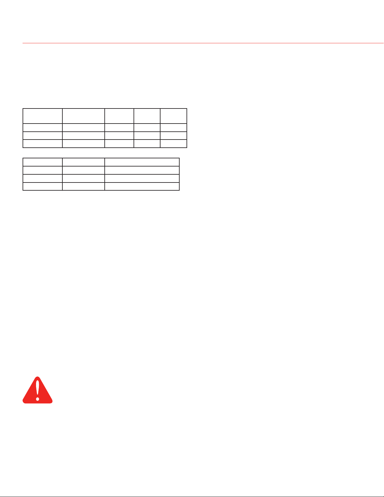
sPeCIfICaTIons
Capacity:
HM512: 12 gallons per day (gpd) (45 liters per day [lpd])
HM509: 9 gpd (34 lpd)
HM506: 6 gpd (23 lpd)
Humidified Area:
House
Description
Loose Two 2000 ft21300 ft21000 ft
Average One 2500 ft21800 ft21500 ft
Tight One-half 3000+ ft22500 ft22000 ft
Air Changes
Per Hour
HM512 HM509 HM506
2
2
2
Weight:
Model Empty Filled with Water
HM512 9 lbs. 15 lbs.
HM509 9 lbs. 14.5 lbs.
HM506 8 lbs. 12 lbs.
• Dimensions: 11-1/4 in. W x 19 in. H x 9 in. D
• Humidifier Operating Temperature Range: 34ºF–
120ºF (1.1ºC–49ºC)
• Remote Hose/Nozzle Operating Temperature Range:
-50ºF–250ºF (-46ºC–121ºC)
• Operating Humidity Range: 0–95% RH, noncondensing
Drain Operation
• Auto flushing is configurable to 10, 20 or 30 hours of
operational time (heating element active).
• During auto flushing, cold water will enter the tank to
lower water temperature below 140ºF (60ºC) before
draining.
• During manual flush (performed by pressing the
EMPTY button) initial water temperature may be
above 140ºF (60ºC). Ensure drain outlet is not
exposed and use caution when pressing the EMPTY
button, and do NOT attempt to remove the tank with
water in it.
• Flush cycle takes approximately 15 minutes to
empty the tank completely. To override, press/hold
the EMPTY button while the “Clean Tank” light is
blinking.
• Drain Hose Operating Temperature Range: 34ºF–
212ºF (1.1ºC–100ºC)
Electrical Ratings and Tolerances
Input Ratings
• Power Supply: 120VAC +10/ -15%, 60Hz
- HM512: 1440W at 120VAC at full load
- HM509: 1200W at 120VAC at full load
- HM506: 840W at 120VAC at full load
• HM512: 12A, 120VAC
• HM509: 10A, 120VAC
• HM506: 7A, 120VAC
• 15A, 120VAC interlock switch
• Thermostat/HVAC power monitor (R to C): 10mA
resistive at 24VAC
• Field wiring terminals: 18–22 ga. solid
• HVAC power/airflow monitor: 10 mA resistive at 24
VAC
Output Ratings
• Relay output contacts:
- Fan: 1.5A full load, 7.5A locked rotor at 24VAC
- Heat and Backup: 15A resistive at 120VAC
• Fill Solenoid: 0.1A at 120VAC, 0.5 PF
• Drain Solenoid: 0.1A at 120VAC, 0.5PF
• Humidistat output contacts: 10mA resistive at 24VAC
• Humidistat power supply: 100mA at 24VAC
CAUTION
Hot water temperature above 140°F (60°C)
can cause burns from scalding.
Standards & Approval Body Requirements
Underwriters Laboratories: UL998, File no. E185662.
Federal Communications Commission: Class B compliance, File no. YU555.
Intended to be used in accordance with the National Electrical Code (NEC), ANSI/NFPA 70, and the rules of the
Canadian Electrical Code (CEC), Part 1, C22.1.
69-2036EFS—07 22
Page 25
TrueSTEAM Humidification System
EMPTY
M24774
CLEAN TANK
(BLINKING LIGHT)
M24775
M24776
CLEAN TANK
(ON SOLID)
CleanIng and seasonal oR VaCaTIon maInTenanCe
Maintenance is simple with TrueSTEAM—just remove the water tank for cleaning.
Warning: Scalding hazard.
Do not attempt to remove the humidifier from the mounting bracket during operation,
or when the humidifier’s water tank when full of water. Water heater could be hot when
tank is removed. Failure to comply could result in severe scalding or death.
Drain Operation
• Auto flushing is configurable to 10, 20 or 30 hours of operational time (heating element
active).
• During auto flushing, cold water will enter the tank to lower water temperature below 140°F
(60°C) before draining.
• During manual flush (performed by pressing the EMPTY button) initial water temperature may
be above 140°F (60°C). Ensure drain outlet is not exposed and use caution when pressing the
EMPTY button, and do NOT attempt to remove the tank with water in it.
To clean the TrueSTEAM:
1. Press and hold the EMPTY button for 3 seconds. Wait for the CLEAN TANK light to be
on solid (not blinking). The flush cycle takes approximately 15 minutes to empty the tank
completely. To override the flush cycle press/hold the EMPTY button a second time for 3
seconds. The tank will drain immediately.
Wait
Go to Step 2
23 69-2036EFS—07
Page 26
Installation Guide
M24777
M24778
M24779
M24856
M24857
CleanIng and seasonal oR VaCaTIon maInTenanCe
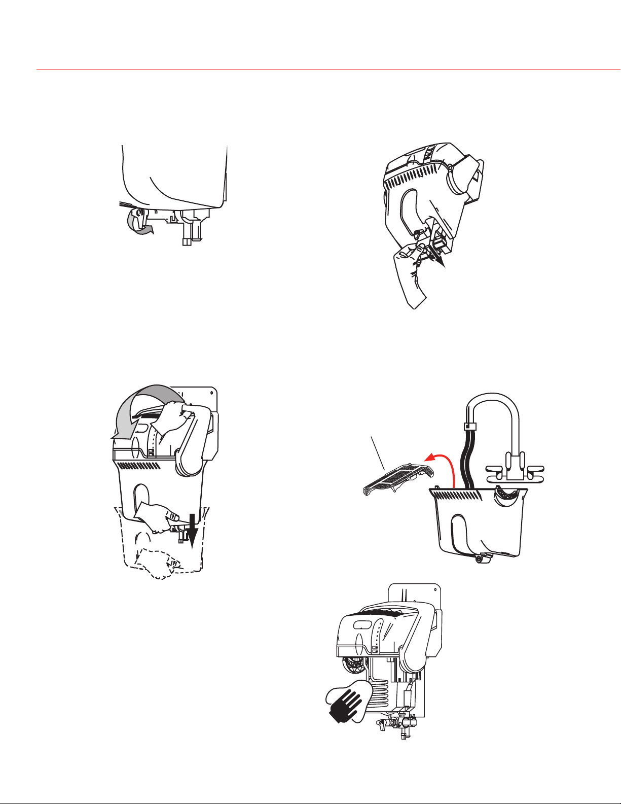
2. Turn the manual shut-off valve at the
bottom of the tank to the “Unlock”
position.
4. Firmly grip the tank bottom. Push down
the cover's safety button and pull the latch
forward to release the tank.
Note: Latch does not come off humidifier
with tank.
3. Grip the white water valve arm and slide it
back within the bracket to disengage from
the tank.
5. Use tap water to flush loose minerals from
the tank. Sediment screen at tank's bottom
is removable. For a more thorough cleaning,
soak tank in warm, soapy water, then rinse
clean. Tank is also dishwasher-safe.
6. Carefully rub minerals off of the heating
element, reservoir walls, and sensors. Scouring
pads suitable for non-stick pots or pans are
suitable for cleaning the TrueSTEAM reservoir
walls and components within the tank.
Sediment screen
69-2036EFS—07 2
Page 27
TrueSTEAM Humidification System
M27410
M27411
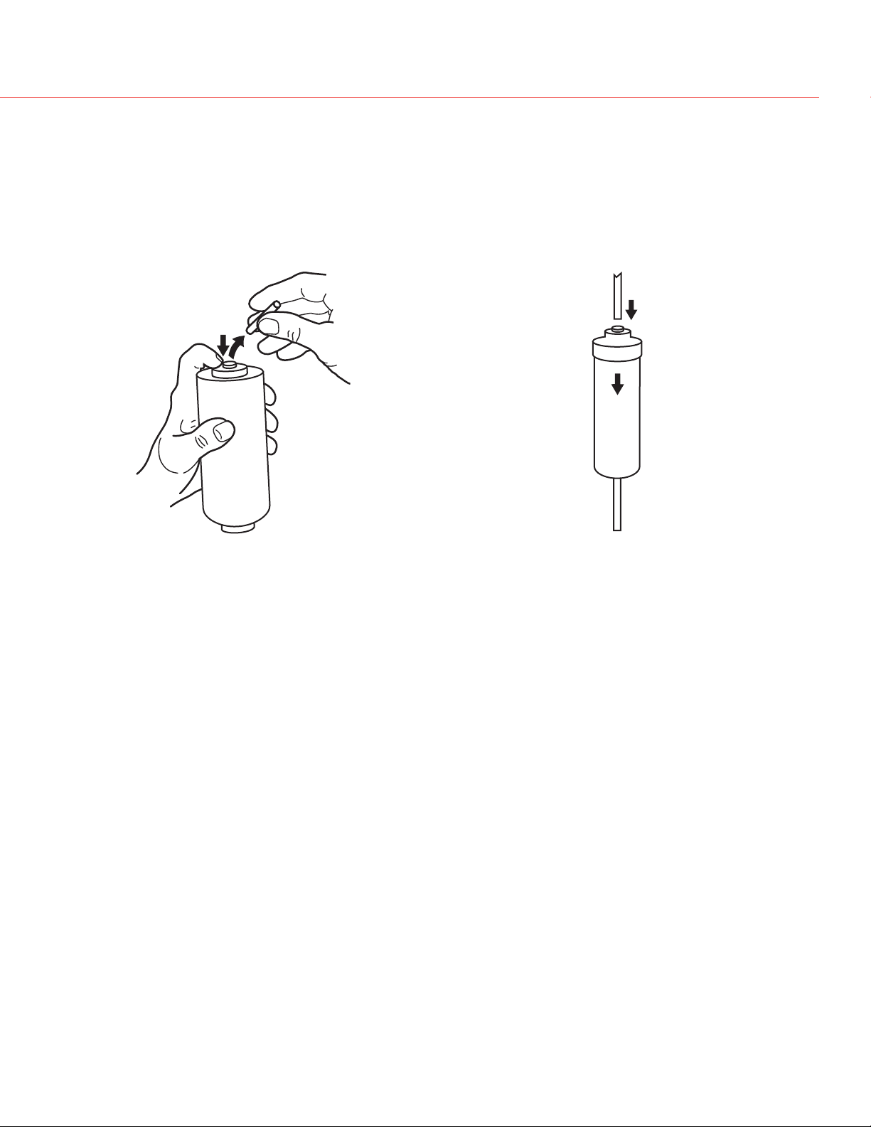
7. Replace inline filter once per year. Turn water supply off before replacing.
Press down filter collar ring and pull
out 1/4 in. water line from each side.
Insert 1/4 in. lines into new filter. Apply
modest pressure to ensure a tight fit.
Once clean, reattach tank by securing the latch. Engage the water valve to the cam shaft, and
“Lock” the shut-off valve. The “Press Reset” light will blink at start-up. Push the RESET button
to ready the humidifier.
2 69-2036EFS—07
Page 28

Installation Guide
CleanIng and seasonal oR VaCaTIon maInTenanCe
Automatic End of Season Shutdown
Your TrueSTEAM humidifier has the built-in intelligence to shut down when humidity is not needed for an extended period. After 48 hours of inactivity, TrueSTEAM will drain and remain empty
until humidity is needed again. This prevents water from stagnating within the tank. The tank will
refill with water upon next humidity call.
There are a few house-cleaning steps to follow to keep your TrueSTEAM operating at peak
efficiency:
1. Follow steps 1–6 in the Cleaning section on page 23 at least once per year, or when the
“Press Empty” light is blinking.
2. Clear ventilation holes in the humidifier’s cover.
3. Clear the water drain tube.
4. Make sure the water tank gasket seal is not cracked or split before reattaching the humidifier
water tank.
5. Check that the humidifier is still mounted level.
Extended Vacation
When you leave on extended vacations, it is recommended you turn off the humidifier’s water
supply and turn off the humidity control. When you return, turn on the humidifier water supply
and reset your humidity control to a comfortable position.
69-2036EFS—07 26
Page 29

TrueSTEAM Humidification System
M24787A
PaRTs lIsTCleanIng and seasonal oR VaCaTIon maInTenanCe
Part Part Number Fig. Reference
10-foot Remote Hose and Nozzle Kit 50024917-001 1
20-foot Remote Hose and Nozzle Kit 50024917-002 1
Cover 50028004-001 2
Duct Nozzle 50028003-001 3
Remote Nozzles 50028001-001 4
Mounting Bracket 50020012-001 5
Solenoid Valve 50027997-001 6
In-Line Water Filter 50028044-001 7
HM512/HM509 Water Tank 50033181-001 8
HM506 Water Tank 50033182-001 9
Water Level Sensor Assembly 50027998-001 10
Saddle Valve 32001616-001 11
Back-flow Water Valve 50030142-001 12
Differential Pressure Switch 50027910-001
13
13
12
1
2
8
3
4
5
6
11
10
9
7
27 69-2036EFS—07
Page 30

Automation and Control Solutions
Honeywell International Inc.
1985 Douglas Drive North
Golden Valley, MN 55422
Honeywell Limited-Honeywell Limitée
35 Dynamic Drive
Toronto, Ontario M1V 4Z9
http://yourhome.honeywell.com
® U.S. Registered Trademark.
© 2008 Honeywell International Inc.
69-2036EFS—07 M.S. Rev. 05-08
Printed in U.S.A. on recycled
paper containing at least 10%
post-consumer paper fibers.
Page 31

Humidificateur TrueSTEAM
Simple comme 1, 2, 3, 4
GUIDE D’INSTALLATION PROFESSIONNELLE
1
3
Monter
Mettre de niveau
2
4
Suspendre
Raccorder
Consulter les pages suivantes pour des instructions détaillées et des options de montage à distance.
Page 32

Guide d’installation
Table des maTIèRes
Recommandations d’installation ................................................. 31
Outils et matériel nécessaires ..................................................... 33
Consignes de sécurité ................................................................. 34
Instructions de montage sur gaine
Installation ..................................................................................... 35
Instructions de montage à distance
Installation ..................................................................................... 37
Plomberie et câblage
Plomberie ...................................................................................... 43
Câblage ......................................................................................... 44
Réglage des commutateurs DIP .................................................. 48
Dépannage .................................................................................... 49
Nettoyage, entretien saisonnier et
avant les absences prolongées ............................................. 53
Renseignements supplémentaires
Nomenclature des pièces ............................................................ 57
Besoin d’aide?
Pour toute assistance concernant ce produit, visitez le site http://yourhome.honeywell.com
ou communiquez avec les Services à la clientèle au numéro sans frais 1-800-468-1502
Veuillez lire les présentes instructions et les
garder à portée de main.
® Marque de commerce enregistrée aux États-Unis.
Brevets en instance.
Copyright © 2007 Honeywell International Inc. Tous droits réservés.
69-2036EFS—07 30
Page 33

Humidificateur à injection directe TrueSteam
ReCommandaTIons d’InsTallaTIon
Pour effectuer correctement l’installation du TrueSTEAM et assurer son bon fonctionnement, il
est important de tenir compte des points suivants :
Capacité de l’appareil
1. Choisir l’humidificateur qui convient à l’application est crucial :
Le tableau ci-dessous indique la superficie en mètres carrés (pieds carrés) qu’un appareil
TrueSTEAM peut humidifier.
Un appareil de 23L (6 gall.) n’est pas recommandé pour les maisons d’une superficie supérieure
à 185 mètres carrés (2000 pieds carrés).
Aire en mètres carrés (pieds carrés)
LPJ (GPJ) recommandés par l’ARI*
TrueSTEAM HM512 - 45 L (12 gall.) réels
TrueSTEAM HM509 - 34 L (9 gall.) réels
TrueSTEAM HM506 - 23 L (6 gall.) réels
* Recommandation F-2007 de l’ARI pour le maintien d’un taux d’humidité relative de 35 % dans une
maison étanche avec plafonds de 2,4 m (8 pi), habitée par quatre personnes. Température de -6 ºC
(20 ºF) et taux d’humidité relative de 70 % à l’extérieur.
45
(500)
0,4
(0,1)
90
(1000)
8,3
(2,2)
140
(1500)
16,6
(4,4)
185
(2000)
24,6
(6,5)
230
(2500)
32,6
(8,6)
280
(3000)
44,3
(11,7)
Liste des vérifications au moment de l’installation
• Installer le filtre de tuyau à eau et la vanne anti-refoulement.
• Vérifier si le tuyau d’alimentation principale en eau est ouvert.
• S’assurer qu’il n’y aucune fuite ni gouttes d’eau à l’un ou l’autre des raccordements d’eau.
• Vérifier si le circuit est suffisant pour alimenter l’appareil.
• Provoquer une demande d’humidification à l’aide du régulateur et vérifier si le TrueSTEAM se
remplit et si le voyant d’humidification s’allume, ce qui indique la production de vapeur.
• Vérifier le fonctionnement du drain en appuyant sur le bouton EMPTY (VIDANGE) jusqu’à ce
que le voyant Clean Tank (Nettoyage du réservoir) commence à clignoter pour indiquer la
mise en marche du cycle de vidange.
REMARQUE : Le nettoyage et la vidange du réservoir peuvent prendre une dizaine
de minutes. Pour sauter l’étape du nettoyage et effectuer la vidange immédiatement,
maintenir enfoncé le bouton EMPTY (VIDANGE) lorsque le voyant Clean Tank (Nettoyage du
réservoir) clignote. Le cycle de nettoyage est annulé et la vidange du réservoir commence
immédiatement. Pour arrêter la vidange, appuyer sur le bouton Reset (Réarmement).
• Apposer l’étiquette d’entretien du réservoir fournie sur la gaine ou le mur près de l’appareil.
Cette étiquette autocollante est jaune. Vérifier si le tuyau de drain est fixé de manière qu’il
ne peut se séparer accidentellement. Vérifier si le tuyau est bien inséré dans le drain ou la
pompe à condensats; autrement l’eau pourrait gicler.
3 69-2036EFS—07
Page 34

Guide d’installation
ReCommandaTIons d’InsTallaTIon
Réglage de l’appareil TrueSTEAM pour un fonctionnement efficace et pour répondre aux
besoins des utilisateurs :
Le point de consigne de l’humidification n’est parfois atteint qu’au bout d’une semaine de
fonctionnement continu de l’appareil, compte tenu de facteurs comme l’aire de la maison, son
contenu et son isolation.
Avec un appareil de 23 L (6 gall.), le meilleur réglage est entre 30 et 35 % ou jusqu’à ce qu’il y ait
de la condensation dans les fenêtres. Il faut alors abaisser le point de consigne (à condition que
l’appareil ne soit pas réglé au mode protection contre le givre). Si le point de consigne n’est pas
atteint, l’appareil n’est peut-être pas assez puissant (si la superficie de la maison est inférieure
à 185 mètres carrés ou 2000 pieds carrés, l’isolation, les fenêtres ou le climat aride peuvent en
être la cause); il est aussi possible que la température extérieure soit trop basse et qu’elle ne
permette pas d’assurer le maintien de niveaux d’humidité adéquats. Il est préférable d’attendre
que la température soit près de -6 °C (20 °F).
Si la température est de cet ordre mais que les niveaux d’humidification sélectionnés ne sont
pas atteints, il faut utiliser un appareil d’une plus grande capacité.
Pendant la première semaine de fonctionnement de l’appareil, il est normal de sentir une légère
odeur de plastique, selon le degré de ventilation dans la maison. Si un tuyau à distance est
utilisé, il peut y avoir une légère odeur de caoutchouc. Ces odeurs disparaîtront dans les jours
suivant l’installation.
Si le TrueSTEAM ne se met pas en marche malgré une demande d’humidification, c’est
probablement parce qu’il est en mode vidange. Demander au propriétaire de revérifier le
fonctionnement de l’appareil au bout d’une heure.
Si le voyant Call Service (Appel de service) clignote, demander au propriétaire de maintenir
enfoncé le bouton de réarmement pour corriger le problème. Si le problème dure, débrancher
l’appareil, puis le rebrancher dans la prise de courant. Attendre 24 heures avant d’appeler un
entrepreneur. Le voyant d’appel de service clignote peut-être parce que la tension est basse
dans les environs; l’appareil devrait recommencer à fonctionner correctement une fois le courant
revenu à la normale.
La consommation d’énergie peut augmenter légèrement. Par contre, comme la maison semble
plus chaude lorsque le TrueSTEAM fonctionne efficacement, il est possible d’abaisser le point
de consigne du thermostat. Une diminution du point de consigne d’un degré permet de réaliser
des économies de coûts de chauffage pouvant atteindre 3 %.
69-2036EFS—07 32
Page 35

Humidificateur à injection directe TrueSteam
ouTIl eT maTéRIel néCessaIRes PouR l’InsTallaTIon de l’humIdIfICaTeuR TRuesTeam
Outils et quincaillerie nécessaires :
• Pince à dénuder et à couper les fils
• Perceuse ou outil pour découper la gaine
• Scie-cloche de 44 mm (1 3/4 po)
• Foret de 3 mm (1/8 po)
• Tournevis à point cruciforme et tournevis
droit (ou Torx)
• Fil de thermostat de calibre 18 (à 5 ou
à 2 conducteurs)
Matériel fourni :
• Tuyau de 64 mm (1/4 po), en cuivre ou en
plastique
• Tuyau d’évacuation de 127 mm (1/2 po) et
colliers
• Support de montage et quincaillerie
• Filtre de tuyau à eau* (50028044-001)
• Robinet-vanne à étrier
• Vanne anti-refoulement (50030142-001)
Matériel facultatif :
• Ensemble d’installation à distance
– Ensemble tuyau de raccordement de
3 m (10 pi) et buse (50024917-001)
– Ensemble tuyau de raccordement de
6 m (20 pi) et buse (50024917-002)
• Régulateur d’humidité
– Humidistat manuel (H8908ASPST)
– TrueIAQ (DG115EZIAQ)
– VisionPRO IAQ (YTH9421C1010)
• Raccord de tuyau en T
• Robinet de sectionnement
• Siphon de tuyau à distance
• Interrupteur à pression différentielle
(50027910-001)
• Nécessaire de montage à distance pour une
gaine à panneaux (32005530-001)
* La garantie stipule que l’installation d’un filtre à eau en ligne et son entretien à intervalles
réguliers sont obligatoires.
33 69-2036EFS—07
Page 36

Guide d’installation
ConsIgnes de séCuRITé
MISE EN GARDE : Risques liés au courant électrique.
Peut causer des chocs électriques ou endommager l’équipement. Couper
l’alimentation du système CVCA avant de commencer l’installation de l’appareil.
Consignes de sécurité
• Ne pas diriger la buse de vapeur vers des personnes.
• Si l’humidificateur TrueSTEAM est installé près d’une piscine ou d’un spa, s’assurer qu’il ne
peut tomber dans l’eau, ni être éclaboussé. S’assurer également qu’il est branché dans une
prise de courant à disjoncteur de fuite à la terre (DFT).
• L’eau contenue dans le réservoir peut être très chaude. Suivre à la lettre les directives
d’installation et les étapes d’entretien telles qu’elles figurent dans la documentation technique.
Avertissement : Dangers reliés à l’électricité, à l’équipement lourd et aux
produits chimiques
Peut causer la mort, la cécité, des dégâts d’eau et provoquer la panne de élément chauffant.
• Ne couper aucun tuyau de climatiseur, ni aucun fil électrique.
• Porter des lunettes de sécurité pour couper ou percer.
• Installer l’humidificateur de niveau pour éviter les dégâts d’eau ou la panne de l’élément
chauffant.
• Si nécessaire, renforcer la gaine pour assurer la stabilité de l’installation.
De préférence, installer l’appareil sur le côté air chaud ou approvisionnement en air de l’appareil
de chauffage. S’il n’est pas possible de l’installer à cet endroit, la buse de vapeur doit être installée à au moins 30 cm (12 po) en amont du filtre de l’appareil de chauffage. Si nécessaire, selon
l’emplacement et le degré de rigidité de la gaine, installer un renfort de gaine.
Avertissement : Dangers reliés à la condensation de vapeur, au feu et au gel de l’eau.
Peut causer des pannes du ventilateur et des limiteurs ou des dégâts d’eau.
• Ne pas installer l’appareil à un endroit où la température ambiante est inférieure à 0 °C (32 °F) ou
supérieure à 49 °C (120 °F).
• Ne pas installer l’humidificateur sur les parois latérales d’une gaine de retour d’air fabriquée en
bois (p. ex. des solives de plancher).
• La surface de montage doit être assez résistante pour supporter le poids de l’humidificateur
rempli d’eau (approximativement entre 5,4 kg et 6,8 kg [12 et 15 lb]) et pour maintenir l’appareil
de niveau afin d’assurer un fonctionnement sécuritaire et fiable. Sinon, renforcer la gaine ou le
mur.
• Si l’intérieur de la gaine est garni de matériel isolant exposé, enlever l’excès d’isolant au point
d’insertion de manière à bien dégager la buse. Il peut être préférable de remplacer une section
de la gaine isolée (approximativement 15 cm x 15 cm [6 po x 6 po]) par une section de tôle non
isolée pour rendre l’installation adéquate.
• Monter l’appareil à un endroit où le débit d’air est régulier, à l’extrémité de la buse de vapeur.
• Laisser un espace d’au moins 30 cm (1 pi) au dessus des orifices de ventilation dans le couvercle
de l’humidificateur. Ne pas recouvrir ces orifices, ce qui pourrait faire augmenter la température
interne de fonctionnement et raccourcir la durée de vie de l’humidificateur.
• Laisser au moins 10 cm (4 po) de dégagement entre l’orifice d’insertion de la buse de vapeur et le
haut de l’intérieur de la gaine pour éviter la formation de condensation à l’intérieur de la gaine. Le
gabarit de montage est conçu pour assurer ce dégagement si sa partie supérieure est placée à
égalité ou en dessous de la surface supérieure de l’intérieur de la gaine.
• Ne pas monter l’appareil directement sur une gaine à panneaux. L’adaptateur de buse à distance
ne peut être utilisé qu’avec le nécessaire d’adaptation pour une gaine à panneaux (pièce
32005636-001).
• Ne pas installer l’appareil dans un espace totalement clos comme une armoire ou un placard non
aéré. Choisir un emplacement bien ventilé.
69-2036EFS—07 3
Page 37

Humidificateur à injection directe TrueSteam
M24744
M24745
M24746
M24894
MF24914
Pour une installation sur la gaine de soufflage, suivre les instructions aux pages 35 et 36 et aux
pages 43 à 48. Pour une installation à distance, suivre les instructions aux pages 37 à 48.
InsTallaTIon suR gaIne
Choisir un emplacement qui donne
1
accès à :
• un drain permettant de donner au
tuyau d’évacuation une pente de
2 cm par mètre (1/4 po par pied);
• un tuyau d’eau froide;
• un circuit électrique de capacité
suffisante;
• une surface verticale offrant un
dégagement suffisant.
Pente
régulière
L’eau de vidange
peut être chaude.
S’assurer que la
sortie du drain
n’est pas exposée.
2
Installer la buse de gaine.
Capacité minimale du
Modèle
circuit électrique
HM506 7 ampères
HM509 10 ampères
HM512 12 ampères
AVERTISSEMENT
L’eau chaude à une température qui dépasse 120 °F
(49 °C) peut causer des brûlures par ébouillantage.
S’assurer que le
joint torique est
bien posé dans sa
rainure.
Insérer la buse et la tourner dans le
sens horaire pour que le joint entre la
buse et le TrueSTEAM soit étanche.
3 69-2036EFS—07
Page 38

Guide d’installation
M24749
M24750
MF24748
APPROVISIONNEMENT
30 CM (12 PO)
InsTallaTIon suR gaIne
Placer le gabarit autocollant sur la gaine de soufflage. Dans le cas où les
3
grands serpentins ne permettent de laisser un dégagement suffisant, suivre les
instructions de montage à distance.
4
Percer un trou de 4,5 cm
(1 3/4 po).
Fixer le support à la gaine avec 4
5 6
vis à métal autotaraudeuses no 8
A) Glisser le joint en mousse par-dessus la
buse et insérer la buse dans l’orifice de
la gaine (voir l’illustration).
B) Pousser l’humidificateur vers le bas de
manière à bien le fixer sur le support.
S’assurer que le joint en mousse dans
l’orifice de la gaine est bien étanche.
Allouer un
dégagement de
3 po entre la sortie
de la buse et la
paroi de la gaine.
B
A
Joint en
mousse
Passer à la page 43 pour les directives concernant la plomberie et le câblage.
69-2036EFS—07 36
Page 39

Humidificateur à injection directe TrueSteam
M24896A
InsTallaTIon à dIsTanCe
Suivre ces instructions pour installer l’appareil ailleurs que sur la gaine de soufflage.
La plupart des problèmes de
fonctionnement sont causés par une
mauvaise installation du tuyau. Dans une
installation à distance, toujours s’assurer
qu’il y a une pente ascendante. Éviter
la formation de plis, d’angles aigus ou
points bas qui peuvent restreindre le
flux de la vapeur dans la buse d’injection
ou provoquer sa condensation dans
l’humidificateur.
S’il est impossible d’installer le tuyau
d’installation à distance avec une pente
ascendante de 10,5 cm par mètre (2 po
par pi), installer un raccord en T pour
l’égouttement. Autrement, la pression de
retour dans l’humidificateur TrueSTEAM
peut entraîner la projection d’eau dans la
gaine par la buse ou une fuite du joint. Le
tuyau d’installation à distance doit être
soutenu pour prévenir son affaissement et
les points bas.
Choisir l’emplacement de
1
l’humidificateur TrueSTEAM et
de la buse de gaine à distance.
(Consulter l’installation à distance
aux pages 32 et 33.)
Il faut avoir accès à :
• un endroit permettant d’installer
le tuyau de vapeur avec une
pente ascendante continue de
10,5 cm par mètre (2 po par
pied);
• un drain permettant une pente
descendante continue;
• un tuyau d’eau froide;
Dans le cas d’un montage à distance,
suivre également les étapes suivantes car elles
permettent de choisir l’appareil TrueSTEAM
approprié :
Si le tuyau de distribution de vapeur passe dans
un endroit non chauffé, par exemple un grenier,
isoler ce tuyau pour assurer la sortie efficace de
la vapeur :
• Un isolant autoscellant pour tuyaux d’eau
chaude et d’eau froide est recommandé. Tuyau
isolé de 29 mm (1 1/8 po) de diam. int. x 38
mm (1,5 po), homologué Factory Mutual 25/50,
no 062411, ignifuge.
Le modèle HM506 de 23 L (6-gall.) peut être
monté à une distance maximale de :
• 1,5 mètre (5 pieds) avec tuyau de distribution
de vapeur non isolé
• 4,5 mètres (15 pieds) si le tuyau de distribution
de vapeur est isolé
Les modèles HM509 et HM512, respectivement
de 34 L (9 gall.) et 45 L (12-gall.) peuvent être
montés jusqu’à une distance de 6 mètres (20
pieds) avec un tuyau de distribution de vapeur
isolé ou non isolé.
Prévoir une pente ascendante d’au moins 10,5
cm par mètre (2 po par pi) si le tuyau à distance
est installé à l’horizontale.
Maximum de 90 cm (3 pi)
Pente ascendante
de 10,5 cm/m (2 po/pi)
• un circuit électrique de
capacité suffisante (consulter
l’information sur les capacités
du circuit à la page 40).
Entonnoir ou drain de plancher. Consulter les codes
de construction pour connaître les exigences
relatives à la dimension et la température maximale.
37 69-2036EFS—07
15 cm (6 po)
20 cm (8 po)
Diamètre
minimum de
1,3 cm (1/2 po)
Water in elbow
Page 40

Guide d’installation
M24786
M24781
M24785
MF24936
FLUX DESCENDANT
InsTallaTIon CoRReCTe du Tuyau
À distance dans la pièce de chauffage
ou des installations mécaniques
Remarque : Si la température à l’endroit où est
situé l’appareil de conditionnement de l’air peut
descendre en dessous du point de congélation, il
faut installer l’humidificateur TrueSteam dans un
endroit chauffé et amener un tuyau jusqu’à la gaine.
Montage sur gaine à
distance
AVERTISSEMENT
L’eau chaude à une température qui
dépasse 120 °F (49 °C) peut causer
des brûlures par ébouillantage.
Installation dans des pièces habitées
À distance dans le garage
L’eau de
vidange peut
être chaude.
S’assurer
que la
sortie du
drain n’est
pas exposée.
69-2036EFS—07 3
Page 41

10,5 CM/M (2 PO/PI)
10,5 CM/M (2 PO/PI) 10,5 CM/M (2 PO/PI)
10,5 CM/M
(2 PO/PI)
MAX 6 M (20 PI)
AVEC SIPHON
MAX 1,5M (5 PI)
SI AUCUNE PENTE
SIPHON
SIPHON
VIDANGE
MAX 90 CM (3 PI)
MAX 3 M (10 PI)
COURBE FAIBLE
OBSTRUCTION
TUYAU D’INSTALLATION À DISTANCE SOUTENU
MAX 6 M (20 PI)
VIDANGE
SIPHON
REMARQUE : LA HAUTEUR DU SIPHON DOIT ÊTRE
SUPÉRIEURE À LA PRESSION STATIQUE DE LA GAINE.
VIDANGE
INSTALLATION TYPE SI
LE TrueSTEAM EST INSTALLÉ
AU-DESSUS DE LA BUSE À DISTANCE
PLI
POINT BAS
PAS DE PENTE
PAS DE PENTE
MF24915
COUDE
SANS VIDANGE
Humidificateur à injection directe TrueSteam
InsTallaTIon CoRReCTe du Tuyau
REMARQUES :
• Diriger le tuyau vers le haut avec une pente de 10,5 cm par mètre (2 po par pi)
dans le sens du flux de vapeur.
• Diriger le tuyau vers le bas avec une pente de 4 cm par mètre (3/4 po par pi).
• Le tuyau d’installation à distance POUR la vapeur doit avoir une longueur
maximale de 6 m (20 pi)
• La hauteur du siphon doit être supérieure à la pression statique de la gaine.
Normalement, une hauteur de 8 cm (3 po) est suffisante. Le siphon doit aussi
être muni d’un dispositif d’égouttement (voir à la page 37).
• Réduire au minimum les angles aigües et les coudes.
• Dans des espaces sans chauffage ni refroidissement, l’efficacité du tuyau
d’installation à distance sera plus grande si celui-ci est isolé.
ÉVITER CES ERREURS D’INSTALLATION.
39 69-2036EFS—07
Page 42

Guide d’installation
M24744
M24745
M24764
M24765
M24894
InsTallaTIon à dIsTanCe
Capacité minimale du
Modèle
circuit électrique
HM506 7 ampères
HM509 10 ampères
HM512 12 ampères
Installer l’adaptateur de tuyau four-
2
ni dans l’ensemble d’installation à
distance.
L’eau de vidange
peut être chaude.
S’assurer que la
Pente
Régulière
sortie du drain
n’est pas exposée.
AVERTISSEMENT
L’eau chaude à une température qui dépasse 120 °F
(49 °C) peut causer des brûlures par ébouillantage.
Ensemble d’installation à distance
(vendu séparément)
Adaptateur de tuyau
S’assurer que le joint
torique est bien installé
dans sa rainure.
Colliers de tuyau
Buse de gaine
Tuyau d’installation
à distance
• 50024917-001 = Ensemble de tuyau de
raccordement de 3 m (10 pi)
• 50024917-002 = Ensemble de tuyau de
raccordement de 6 m (20 pi)
69-2036EFS—07 0
Insérer la buse et la tourner dans le
sens horaire pour que le joint entre la
buse et le TrueSTEAM soit étanche.
Page 43

M24766
3
M24767A
M24768
Humidificateur à injection directe TrueSteam
InsTallaTIon à dIsTanCeInsTallaTIon à dIsTanCe
Placer le gabarit autocollant à l’emplacement
d’installation à distance.
Remarque : L’humidificateur TrueSTEAM pèse entre
5,4 à 6,8 kg (+/- 1 kg) (12 à 14 lb (+/- 2 lb) une fois
qu’il est rempli d’eau. S’il est monté sur un mur de
plâtre ou de placoplâtre, installer un des côtés de
l’humidificateur sur un montant du mur.
4
Poser 4 ancrages de mur dans des trous pilotes et
fixer le support en position.
5
Pousser l’humidificateur vers le bas
pour bien le fixer sur le support.
69-2036EFS—07
Page 44

Guide d’installation
M24770
M24771
InsTallaTIon à dIsTanCe
Découper un trou de 4,4 cm (1 3/4 po) dans la
gaine. Installer le joint fourni. Insérer la buse à
6
7
distance dans la gaine. Fixer la buse à la gaine
avec 4 vis à métal autotaraudeuses no 8.
Installer le tuyau
d’installation à distance
entre l’humidificateur et la
buse. Ce tuyau doit avoir
une longueur maximale
de 6 m (20 pi).
Un dégagement minimal de 3 po
est requis entre la sortie de la
buse et la paroi de la gaine
8
9
Si le tuyau à distance doit passer
dans un élément de structure (par. ex.
un mur ou un plafond), découper un
trou d’au moins 4,4 cm (1 3/4 po) pour
l’installer.
Sceller les espaces sans chauffage
ni refroidissement avec une rondelle
(non fournie) ou du calfeutrage.
Fixer le tuyau d’installation à distance à la buse
et à son adaptateur en le glissant par-dessus l’un
et l’autre. Fixer le tuyau aux deux bouts avec les
colliers fournis.
IMPORTANT :
Installer le tuyau avec une pente ascendante continue. Dans le cas d’une installation horizontale,
s’assurer de conserver une pente ascendante de
10,5 cm par mètre (2 po par pied). Fixer le tuyau à
tous les 30 cm (12 po) avec les colliers fournis.
Dans le cas d’un long circuit horizontal, soutenir le
tuyau en le fixant sur un montant de 61 x 122 cm
(2 x 4 po), un profilé en U ou une cornière, installés
selon la pente appropriée. Si une section du tuyau
doit être installée avec une pente descendante,
consulter les instructions aux pages 35 et 37.
69-2036EFS—07 2
Page 45

Humidificateur à injection directe TrueSteam
M27428
M24852
M24772
10
A
PlombeRIe
Insérer le tuyau d’eau de 64 mm (¼ po) dans le filtre. Appliquer une légère pression
pour assurer l’étanchéité.
B
Insérer le tuyau d’eau de 64 mm (¼ po) dans la vanne anti-refoulement. Appliquer
une légère pression pour assurer l’étanchéité.
C
Raccorder un tuyau d’évacuation de 1,3 cm (1/2 po). Fixer le tuyau d’évacuation au
raccord cannelé avec un collier à tuyau.
D
Couper l’alimentation en eau. Installer un tuyau d’alimentation en eau en cuivre ou
en plastique de 0,64 cm (1/4 po).
A
1/4-in. copper
or plastic
Description Numéro
Filtre de tuyau à eau (compris)
(requis pour la garantie)
Vanne anti-refoulement
(comprise) (requise)
Vers l’alimentation en eau
B
50028044-001
50030142-001
C D
Vue agrandie
Pente
continue
L’eau de vidange peut
être chaude. S’assurer
que la sortie du drain
n’est pas exposée. Vérifier
Tuyau
d’évacuation
de 1,3 cm
(1/2 po)
Tuyau d’alimentation
en eau de 0,64 cm
(1/4 po)
si le drain et la pompe à
condensats sont conçus
pour les applications où
la température de l’eau
peut atteindre 49 °C
AVERTISSEMENT
L’eau chaude à une température qui dépasse 120 °F
(49 °C) peut causer des brûlures par ébouillantage.
(120 °F).
Autres options de raccordement du tuyau d’alimentation en eau. Voir les instructions correspondant à l’option choisie.
Raccord en T
Pointeau
Robinet de
sectionnement
(vendu séparément)
Robinet-vanne à étrier
Vers l’humidificateur
Vers l’humidificateur
Tuyau d’alimentation en eau
Vérifier tous les raccords des tuyaux pour s’assurer qu’il n’y a aucune fuite, une fois le
TrueSTEAM en marche.
3 69-2036EFS—07
Page 46

Guide d’installation
M24754
M24895
24V
24V
HUM
HUM
C
GT
R
RT
GF
EXT
M24893
CÂblage
Desserrer la vis imperdable du
11
MISE EN GARDE : Risque de chocs électriques.
Avant d’effectuer le raccordement aux bornes de l’appareil
CVCA, débrancher l’appareil. S’assurer que l’humidificateur
est débranché.
Bornes basse tension
24V Alimentation c.a. pour un humidistat électronique.
HUM Bornes basse tension de l’humidistat ou du thermostat
C, R Se raccordent aux bornes du transformateur de l’appareil
RT Se raccorde à la borne R du thermostat, qui sert
GT, La borne GT se raccorde à la borne G du thermostat.
GF
EXT Si la mise en marche du ventilateur n’est pas commandée
Pattes
Faire passer les fils entre les pattes ouvertes de l’attache-fil et dans l’encoche à l’arrière du
Encoche
boîtier. S’assurer que les fils sont bien fixés et ne nuisent pas au montage du couvercle.
couvercle. Enlever le couvercle
en le glissant vers l’avant.
commandant le fonctionnement de l’humidificateur.
CVCA ou aux bornes R et C du transformateur du relais de
commande du ventilateur. Permet d’assurer que l’appareil
CVCA est en marche avant de faire fonctionner l’humidificateur.
Cette fonction peut être désactivée en changeant le réglage du
commutateur DIP 4 (voir à la page 46).
normalement à transmettre les demandes de mise en marche
du ventilateur.
La borne GF se raccorde à la borne G du panneau du
ventilateur. Le signal de la borne G se rend à la borne
GF, par les contacts normalement fermés du relais, pour
activer le ventilateur. Quand le TrueSTEAM est prêt à fournir
de l’humidité à la maison, il commande le ventilateur en
faisant passer le courant de la borne RT à la borne GF si le
ventilateur n’est pas déjà en marche.
par un panneau de 24 V c.a. (dans les applications à eau
chaude ou de refroidissement seulement), le raccordement
de cette borne avec la borne GF assure la fermeture
à contact sec pour les demandes de ventilation. Les
bornes EXT et GF peuvent être raccordées à un centre de
commande à relais basse tension pour la commande du
ventilateur par la tension secteur.
69-2036EFS—07
Page 47

APPAREIL CVCA
COMMUTATEUR DE
DÉBIT D’AIR (CDA)
RECOMMANDÉ
HUMIDISTAT
MÉCANIQUE
ALIMENTATION
PRINCIPALE DE
L’APPAREIL CVCA
THERMOSTAT
HUM
HUM
GYWR Rc
GYWRC
INTÉRIEUR DU TrueSTEAM
24V
24V
HUM
HUM
C
GT
R
RT
GF
EXT
MF24756
Consulter le schéma de raccordement qui correspond à l’application avec
PANNEAU DE
CHAUFFAGE ET
VENTILATION
MODULE D’INTERFACE DE L’ÉQUIPEMENT
G
C
24V
24V
HUM
HUM
C
GT
R
RT
GF
EXT
CONV. HP
1
2
3
C
R
RC
RH
W1
W2
W3
Y
Y2
G
O/B
AUX
AUX2
Y
Y2
G
H1
U
M2
D1
H
M2
V1
N
T2
HEAT 1 RELAY
HEAT 2 RELAY
HEAT 3 RELAY
COOL 1 RELAY
COOL 2 RELAY
FAN RELAY
VISIONPRO IAQ
D-1
R-2
C-3
MF24758
COMMUTATEUR DE DÉBIT
D’AIR (CDA) RECOMMANDÉ
INTÉRIEUR
DU TrueSTEAM
HVAC
TrueIAQ
THERMOSTAT
HUM
HUM
R
C
GYWR Rc
GYWR C
24V
24V
HUM
HUM
C
GT
R
RT
GF
EXT
RECOMMENDED
AIR FLOW
SWITCH (AFS)
M27409
HVAC
POWER
MASTER
TrueSTEAM - INTERNAL
12
Se servir de ce schéma dans une application avec
un humidistat mécanique comme le H8908ASPST.
l’humidificateur TrueSTEAM.
Humidificateur à injection directe TrueSteam
CÂblage
Suivre le schéma suivant pour le raccordement du
TrueIAQ utilisé en mode manuel.
Régler le paramètre 10 du IAQ à 1 et régler le
A
paramètre 25 à 2.
Pour le fonctionnement en mode automatique,
B
raccorder également les bornes W et G aux bornes du
thermostat W et G.
B
A
Cavalier
installé à
l’usine
Cavalier
Si un CDA est installé,
mettre le commutateur DIP
installé à
l’usine
5 à la position ON.
Si un CDA est installé, mettre le
commutateur DIP 5 à la position ON.
Se servir de ce schéma dans une application avec un VisionPRO IAQ pour la commande indépendante
du ventilateur. L’humidificateur TrueSTEAM commande de façon indépendante le ventilateur de
l’appareil CVCA (humidité sur demande).
Régler le paramètre 374 du
A
VisionPRO IAQ à 3.
Lorsqu’on fait fonctionner
B
l’humidificateur TrueSTEAM sans
surveillance de l’alimentation de
l’appareil CVCA ou sans CDA,
le raccordement de la borne C
est optionnel. Régler alors le
commutateur DIP 4 à la position
ON.
Si un CDA est installé, mettre le
commutateur DIP 5 à la position
ON.
69-2036EFS—07
A
B
Page 48

Guide d’installation
G
C
24V
24V
HUM
HUM
C
GT
R
RT
GF
EXT
CONV. HP
1
2
3
C
R
RC
RH
W1
W2
W3
Y
Y2
G
O/B
AUX
AUX2
Y
Y2
G
H1
U
M2
D1
H
M2
V1
N
T2
HEAT 1 RELAY
HEAT 2 RELAY
HEAT 3 RELAY
COOL 1 RELAY
COOL 2 RELAY
FAN RELAY
VISIONPRO IAQ
D-1
R-2
C-3
MF24761
PANNEAU DE
CHAUFFAGE ET
VENTILATION
MODULE D’INTERFACE DE L’ÉQUIPEMENT
COMMUTATEUR
DE DÉBIT
D’AIR (CDA)
RECOMMANDÉ
INTÉRIEUR DU TrueSTEAM
ALIMENTATION
PRINCIPALE DE
L’APPAREIL CVCA
24V
24V
HUM
HUM
C
GT
R
RT
GF
EXT
HUMIDISTAT
HUM
HUM
HAC
HAC
HUM
HUM
HAC
HAC
120 V c.a.
R8222
ROUGE
NOIR
L1
L2
120
V c.a.
AT120
R C
MF24760
COMMUTATEUR
DE DÉBIT
D’AIR (CDA)
RECOMMANDÉ
INTÉRIEUR
DU TrueSTEAM
HUMIDISTAT
MÉCANIQUE
APPAREIL CVCA
ALIMENTATION PRINCIPALE
DE L’APPAREIL CVCA
CÂblage
Se servir de ce schéma dans une application avec un VisionPRO IAQ où la mise en marche du système
dépend de l’alimentation de l’appareil de chauffage (humidification et ventilation commandées par le
thermostat).
Régler le paramètre 374
B
du VisionPRO IAQ à 1. Ce
réglage permet au thermostat
de mettre le ventilateur en
B
marche lorsqu’il fait fonctionner
l’humidificateur.
S’il n’y a pas de CDA, régler
le commutateur DIP 4 à la
position ON et ne raccorder que
les bornes HUM.
Si un CDA est utilisé, régler
le commutateurs DIP 5 à la
position ON, et le DIP 4 à la
position OFF; raccorder les
bornes R, C et HUM.
Suivre ce schéma dans une installation où le ventilateur est utilisé seulement avec l’humidificateur
TrueSTEAM (ventilateur indépendant de l’appareil CVCA, comme dans un système à eau chaude ou un
système de refroidissement seulement).
69-2036EFS—07 6
Si un CDA est utilisé, régler
le commutateur DIP 5 à la
position ON.
Enlever le cavalier installé
en usine (R/RT).
Page 49

13
POWER
HUMIDIFYING
CLEAN TANK
CALL SERVICE
PRESS RESET
PRESS EMPTY
RESET
EMPTY
SEE LABEL BELOW
!
M24763
M24762
Humidificateur à injection directe TrueSteam
Glisser le couvercle en place et le fixer avec la vis
imperdable. Ouvrir l’eau et brancher l’humidificateur.
Le voyant PRESS RESET (APPUYER
14
SUR RÉARMEMENT) clignote quand
l’appareil est mis sous tension.
Appuyer sur le bouton RESET
(RÉARMEMENT) pour mettre en
marche le TrueSTEAM. Si le bouton
n’est pas enfoncé dans un intervalle
de cinq minutes, Le TrueSTEAM
passe automatiquement en mode
READY (PRÊT).
CÂblageCÂblage
15
16
Régler le régulateur d’humidité à la position « Test ». Si cette position n’existe
pas, le régler à un point de consigne élevé, soit plus de 60 %. Ne pas oublier de
baisser le réglage ou d’arrêter le régulateur à la fin de l’essai. La position OFF met
l’humidificateur TrueSTEAM hors fonction.
Vérifier que le ventilateur de l’appareil de chauffage est en marche de manière à
faire circuler l’air. Le ventilateur se met en marche 10 à 15 minutes après la demande
d’humidification.
Important dans le cas d’une installation à distance :
Après 10 à 15 minutes de production de vapeur, s’assurer qu’aucun point bas ne se
forme dans le tuyau. Ajouter des colliers ou les ajuster si nécessaire pour assurer une
pente continue de 10,5 cm par mètre (2 po par pied).
7 69-2036EFS—07
Page 50

Guide d’installation
M24853
OFF
ON
OFF
ON
OFF
ON
DIP 1
DIP 2
DIP 3
DIP 4
DIP 5
DIP 6
DIP 1
DIP 2
DIP 3
DIP 4
DIP 5
DIP 6
DIP 1
DIP 2
DIP 3
DIP 4
DIP 5
DIP 6
DIP
3
DIP
3
D
IP
3
D
IP
6
D
IP
6
DIP
6
M28181
DIP 1
DIP 2
DIP 3
DIP 4
DIP 5
DIP 6
DIP 1
DIP 2
DIP 3
DIP 4
DIP 5
DIP 6
OFF
ON
OFF
ON
DIP 1
DIP 2
DIP 3
DIP 4
DIP 5
DIP 6
OFF
ON
DIP
3
D
IP
3
DIP
3
D
IP
6
DIP
6
D
IP
6
Réglage des CommuTaTeuRs dIP
Deux groupes de commutateurs DIP sont situés sur le panneau de circuit entre le transformateur et les
voyants à DEL. Les commutateurs DIP 1 et DIP 2 servent à configurer les cycles de nettoyage. Les commutateurs DIP 4 et DIP 5 permettent de simplifier le raccordement. Actuellement, les commutateurs DIP 3
et DIP 6 ne servent pas. Consulter le tableau ci-dessous pour connaître le détail des réglages.
Durée de fonctionnement
(heures)
10 heures de fonctionnement avant
la vidange automatique des débris du
réservoir.
20 heures de fonctionnement avant
la vidange automatique des débris du
réservoir.
30 heures de fonctionnement avant
la vidange automatique des débris du
réservoir.
Minuterie de fin de
saison (heures)
Après 48 heures
d’inactivité, une vidange
automatique est effectuée; le réservoir reste
vide jusqu’à la prochaine
demande d’humidité.
Après 48 heures
d’inactivité, une vidange
automatique est effectuée; le réservoir reste
vide jusqu’à la prochaine
demande d’humidité.
Après 48 heures
d’inactivité, une vidange
automatique est effectuée; le réservoir reste
vide jusqu’à la prochaine
demande d’humidité.
Indicateur de nettoyage du
réservoir
1 année complète (que l’appareil
fonctionne ou non), avant
que le voyant PRESS EMPTY
(APPUYER SUR VIDANGE) ne
clignote pour indiquer qu’il est
temps de nettoyer manuellement
le réservoir d’eau.
1 année complète (que l’appareil
fonctionne ou non), avant
que le voyant PRESS EMPTY
(APPUYER SUR VIDANGE) ne
clignote pour indiquer qu’il est
temps de nettoyer manuellement
le réservoir d’eau.
1 année complète (que l’appareil
fonctionne ou non), avant
que le voyant PRESS EMPTY
(APPUYER SUR VIDANGE) ne
clignote pour indiquer qu’il est
temps de nettoyer manuellement
le réservoir d’eau.
DIP 4 OFF, DIP 5 ON : Si, deux minutes après une demande de
ventilation, il n’y a pas de débit d’air*, l’humidificateur TrueSTEAM arrête
la production de vapeur et fait clignoter un voyant indiquant le besoin
d’entretien.
*Un commutateur de débit d’air doit être installé. Consulter la section Raccordement.
DIP 4 ON, DIP 5 ON ou OFF : L’humidificateur TrueSTEAM produit de
l’humidité même si l’appareil CVCA n’est pas alimenté et s’il n’y a pas de
débit d’air.
DIP 4 OFF, DIP 5 OFF : L’humidificateur TrueSTEAM ne produit pas
69-2036EFS—07
d’humidité si le système CVCA n’est pas alimenté.
Page 51

Humidificateur à injection directe TrueSteam
M24901
déPannage
L’humidificateur TrueSTEAM est doté d’un système de diagnostic qui surveille le fonctionnement du système,
fait fonctionner les minuteries d’entretien et indique les problèmes en cours. Si le système détecte un problème de fonctionnement, il essaie de rétablir lui-même le fonctionnement dans les 24 heures. S’il en est
incapable, le voyant rouge CALL SERVICE (APPEL DE SERVICE) s’allume.
Le voyant CALL SERVICE (APPEL DE SERVICE) est rouge lorsque le système de diagnostic a identifié un
problème que l’humidificateur ne peut régler de lui-même. Le tableau ci-dessous décrit les problèmes possibles et la procédure de dépannage.
Si le voyant rouge CALL SERVICE (APPEL DE SERVICE) est allumé, appuyer sur le bouton RESET
(RÉARMEMENT). Le voyant rouge CALL SERVICE (APPEL DE SERVICE) émet alors une série de clignotements qui permet d’identifier le problème. Consulter le tableau ci-dessous pour identifier le problème
qui correspond au nombre de clignotements. Pour corriger le problème, appuyer sur le bouton RESET
(RÉARMEMENT) pendant 5 secondes.
Maintenir le bouton EMPTY (VIDANGE) enfoncé pour éteindre un voyant de minuterie de service (par exemple le voyant PRESS EMPTY (APPUYER SUR VIDANGE).
Appuyer sur le bouton EMPTY (VIDANGE) pour vidanger le réservoir.
Nombre de
clignotements du
voyant rouge
1 Problème de
2 Problème de
A
3 Problème de
4 Surchauffe de
Description du
problème
température
de l’eau ou
au niveau de
l’élément chauffant.
niveau d’eau.
B
remplissage du
réservoir d’eau.
l’élément chauffant
Rétablissement
possible par le
système?
Oui. Le système
revient en mode
READY (PRÊT) si
le problème est
disparu au bout
d’une heure.`
Oui. Le système
revient en mode
READY (PRÊT)
si le problème
est disparu au
bout d’une heure.
5 tentatives de
reprise en 24
heures.
Oui. Le système
revient en mode
READY (PRÊT) si
le problème est
disparu au bout
d’une heure.
Non. • Suivre les instructions de nettoyage décrites aux pages 53-56.
Marche à suivre par un technicien qualifié en CVCA seulement
pour régler le problème
• Débrancher le TrueSTEAM et enlever le couvercle.
• Vérifier la connexion du capteur de niveau d’eau au panneau
électronique.
• Replacer le couvercle et rebrancher le TrueSTEAM.
• Si le problème réapparaît, suivre les étapes de nettoyage aux pages
aux pages 53-56.
• Réinstaller le réservoir et appuyer sur le bouton RESET
(RÉARMEMENT).
• Si le problème réapparaît, remplacer l’élément chauffant par le
modèle de puissance électrique approprié.
• Débrancher l’humidificateur et enlever le couvercle.
• Débrancher le fil du capteur de niveau d’eau, retirer le tamis et
soulever l’attache à charnière à pression.
Enlever l’ensemble capteur de niveau d’eau.
• Nettoyer les sondes du capteur à l’eau chaude savonneuse et
mettre le métal à nu.
• Réinstaller l’ensemble capteur dans l’appareil; replacer le couvercle
et le fixer.
• Rebrancher l’appareil et appuyer sur le bouton RESET
(RÉARMEMENT).
• Si le problème réapparaît, remplacer l’ensemble capteur de niveau
d’eau.
• S’assurer qu’il y alimentation en eau.
• Vérifier s’il y a des fuites dans le joint du réservoir ou l’électrovanne.
• Fermer l’alimentation en eau et remplacer le filtre du tuyau.
• Appuyer sur le bouton RESET (RÉARMEMENT) jusqu’à ce que le
voyant CALL SERVICE (APPEL DE SERVICE) s’éteigne.
• Si le réservoir ne se remplit toujours pas, appuyer sur le bouton
EMPTY (VIDANGE). Si le réservoir ne se vide pas, débrancher
l’appareil et s’assurer que l’eau dans le réservoir est froide.
• Suivre les instructions de nettoyage décrites à la page 53. S’assurer de
bien tenir le réservoir avant de le dégager, surtout s’il est rempli d’eau.
• Enlever tous les débris accumulés au bas du réservoir dans l’orifice
de l’électrovanne.
• Réinstaller le réservoir et brancher l’humidificateur. Appuyer sur le
bouton RESET (RÉARMEMENT).
• Si le réservoir ne se remplit toujours pas, remplacer l’électrovanne.
• Réinstaller le réservoir et appuyer sur le bouton RESET
(RÉARMEMENT).
• Si le problème réapparaît, remplacer l’élément chauffant par le
modèle de puissance électrique approprié.
9 69-2036EFS—07
Page 52

Guide d’installation
déPannage
Nombre de
clignotements du
voyant rouge
5 Tension d’entrée
6 Trop-plein d’eau Oui. Le système
7 Système CVCA
Description du
problème
insuffisante
non alimenté
(détection du
problème seulement si DIP 4 et
DIP 5 = OFF).
Rétablissement
possible par le
système?
Oui. Le système
revient en mode
READY (PRÊT) si
le problème est
disparu au bout
d’une heure.
revient en mode
READY (PRÊT) si
le problème est
disparu au bout
d’une heure.
Oui. Le système
revient en mode
READY (PRÊT) si
le problème est
disparu au bout
d’une heure.
Marche à suivre par un technicien qualifié en CVCA seulement
pour régler le problème
• Débrancher l’appareil, puis le rebrancher, et vérifier si l’alimentation
est rétablie.
• Si le problème réapparaît, débrancher l’appareil et enlever le couvercle.
• Vérifier si tous les fils de raccordement sont en bon état et bien fixés.
• Si le problème réapparaît, remplacer l’humidificateur TrueSTEAM.
Il n’est pas recommandé de réparer l’appareil en cas de perte de la
tension secteur.
• S’assurer que le tuyau d’évacuation n’est pas pincé ni submergé
dans le drain. Vérifier le bon fonctionnement de la pompe à
condensats, s’il y en a une.
• Vérifier si de l’eau sort du tuyau d’évacuation. Si le débit est continu,
suivre les instructions de nettoyage décrites aux pages 53 à 56.
• Appuyer sur le bouton EMPTY (VIDANGE) pour vider le réservoir.
• Régler l’humidistat à la position « Test ».
• Si le problème réapparaît, débrancher le TrueSTEAM.
• Desserrer la vis du couvercle et enlever le couvercle.
• Débrancher la connexion du capteur de niveau d’eau et soulever
l’attache à charnière à pression. Enlever l’ensemble capteur de
niveau d’eau. Voir l’illustration à la page 47.
• Nettoyer les sondes du capteur à l’eau chaude savonneuse et
mettre le métal à nu.
• Réinstaller l’ensemble capteur dans l’appareil; remettre le couvercle
et le fixer.
• Rebrancher l’appareil et appuyer sur le bouton RESET
(RÉARMEMENT).
• Si le problème réapparaît, remplacer l’ensemble capteur de niveau
d’eau et/ou l’électrovanne.
• Débrancher l’appareil, puis le rebrancher, et vérifier si l’alimentation
est rétablie.
• Si non, vérifier l’alimentation du système CVCA. Vérifier le coupecircuit et remplacer le fusible s’il est grillé.
• Débrancher le TrueSTEAM et enlever le couvercle.
• S’assurer que DIP 4 = ON et replacer le couvercle.
• Si le problème réapparaît, s’assurer que le circuit électrique a
les caractéristiques requises pour faire fonctionner l’appareil.
Débrancher les appareils supplémentaires alimentés par le même
circuit. Si le problème disparaît, cela indique que le circuit n’est pas
assez puissant pour faire fonctionner l’appareil.
• Si le problème réapparaît, remplacer l’appareil.
69-2036EFS—07 0
Page 53

Humidificateur à injection directe TrueSteam
déPannage
Nombre de
clignotements du
voyant rouge
8–11 L’entrée du
12 Température
13 Le réservoir ne
14 L’élément chauf-
15 Absence de
Description du
problème
moniteur de protection de soudage de contact
est activée
mais le relais de
protection de
l’élément chauffant ne l’est pas.
du circuit électronique trop
élevée.
se vide pas.
fant ne réussit pas à faire
bouillir l’eau.
débit d’air.
Rétablissement
possible par le
système?
Non • Remplacer l’appareil.
Oui. Le système
revient en mode
READY (PRÊT) si
le problème est
disparu au bout
d’une heure.
Non • L’eau du réservoir pourrait être chaude (>140 ºF [60 ºC]).
Oui. Le système
revient en mode
READY (PRÊT) si
le problème est
disparu au bout
d’une heure.
Oui • Vérifier si l’interrupteur à pression différentielle est installé et
Marche à suivre par un technicien qualifié en CVCA seulement
pour régler le problème
• S’assurer que les orifices de ventilation dans le couvercle ne sont
pas obstrués et que le dégagement est d’au moins 30 cm (1pi).
• S’assurer que l’humidificateur est installé à un endroit où l’air se
maintient entre 0 °C (32 °F) et 40 °C (104 °F).
• Arrêter l’humidistat et laisser le temps au circuit électronique de
refroidir.
• Mettre l’humidistat en marche et appuyer sur le bouton RESET
(RÉARMEMENT).
• La demande d’humidification est indiquée par le voyant rouge
HUMIDIFYING (HUMIDIFICATION) qui s’allume.
• Laisser le temps à l’appareil de produire de la vapeur, puis vérifier
les fuites de vapeur près du réservoir et des orifices de ventilation.
• S’il y a des fuites, remplacer l’appareil.
• Appuyer sur le bouton EMPTY (VIDANGE).
• Si l’appareil ne se vide pas, attendre que l’eau du réservoir
refroidisse. S’assurer que l’eau est froide avant de poursuivre.
• Une fois l’eau refroidie, nettoyer le réservoir en suivant les
instructions décrites aux pages 53 à 56.
• Réinstaller le réservoir et appuyer sur le bouton RESET
(RÉARMEMENT).
• Si le problème réapparaît, remplacer l’électrovanne.
• Suivre les étapes de nettoyage du réservoir (pages 53 à 56).
• Réinstaller le réservoir et appuyer sur le bouton RESET
(RÉARMEMENT).
• Si le problème réapparaît, remplacer l’élément chauffant par le
modèle de puissance électrique approprié.
raccordé correctement. Consulter la section Raccordement et
s’assurer que l’appareil et le capteur sont bien raccordés.
• S’assurer que les commutateurs DIP sont bien réglés.
• Si le problème continue, remplacer le capteur de débit d’air ou
l’appareil.
69-2036EFS—07
Page 54

Guide d’installation
CaRaCTéRIsTIques TeChnIques
Capacité :
HM512 : 45 litres par jour [l/j] (12 gallons par jour [g/j])
HM509 : 34 l/j (9 g/j)
HM506 : 23 l/j (6 g/j)
Aire humidifiée :
Étanchéité
de la
maison
Peu étanche Deux 185 m2120 m295 m
Renouvellements
d’air par heure
HM512 HM509 HM506
2
Moyenne Un 230 m2170 m2140 m
Étanche Un-demi 280+ m2230 m2185 m
Poids :
Modèle Vide Rempli d’eau
HM512 4,1 kg (9 lb) 6,8 kg (15 lb)
HM509 4,1 kg (9 lb) 6,6 kg (14,5 lb)
HM506 3,6 kg (8 lb) 5,4 kg (12 lb)
• Dimensions : Larg. 29,8 cm (11 1/4 po); haut. 48,3 cm
(19 po); prof. 22,9 cm (9 po)
• Gamme de température de fonctionnement de
l’humidificateur : 1,1 ºC à 49 ºC (34 ºF à 120 ºF)
• Gamme de température du tuyau de raccordement à
distance et de la buse : -46º C à 121 ºC (-50 ºF à 250 ºF)
• Gamme de fonctionnement de l’humidité :
0 % à 95 %, sans condensation
Fonctionnement du drain
• Il est possible de régler un cycle de vidange
automatique toutes les 10, 20 ou 30 heures de temps
de fonctionnement (élément chauffant actif).
• Pendant la vidange automatique, de l’eau froide sera
ajoutée au réservoir afin de réduire la température à
moins de 140 °F (60 °C) avant que la vidange n’ait lieu.
• Aux premières secondes de la vidange manuelle (que
l’on effectue en appuyant sur le bouton EMPTY), la
température de l’eau atteint parfois plus de 140 °F
(60 °C). S’assurer que la sortie du drain n’est pas
exposée et procéder avec précautions avant d’appuyer
sur le bouton EMPTY. Ne PAS retirer le réservoir s’il
contient encore de l’eau.
• Le nettoyage du réservoir peut prendre 15 minutes
environ. Pour sauter le cycle de nettoyage, maintenir
enfoncé le bouton EMPTY (VIDANGE) lorsque le
voyant Clean Tank (Nettoyage du réservoir) (Nettoyer le
réservoir) clignote.
• Gamme de température du tuyau d’évacuation :
1,1 °C à 100 °C (34 °F à 212 °F)
Caractéristiques électriques nominales et tolérances
Entrées
• Alimentation : 120 V c.a. +10 %, -15 %, 60 Hz
- HM512 : 1440 W sous 120 V c.a., pleine charge
- HM509 : 1200 W sous 120 V c.a., pleine charge
- HM506 : 840 W sous 120 V c.a., pleine charge
• HM512 : 12 A, 120 V c.a.
• HM509 : 10 A, 120 V c.a.
• HM506 : 7 A, 120 V c.a.
2
• Interrupteur d’asservissement : 15 A, 120 V c.a.
2
• Moniteur de la tension du thermostat ou du système
CVCA (R à C) : 10 mA, résistif, sous 24 V c.a.
• Bornes de raccordement sur place : pleines, de calibre
18 à 22
• Détecteur d’alimentation de l’appareil CVCA et du débit
d’air : 10 mA, résistif, sous 24 V c.a.
Sorties
• Contacts de sortie à relais
- Ventilateur : 1,5 A pleine charge, 7,5 A avec rotor
bloqué, sous 24 V c.a.
- Chauffage et chauffage d’appoint : 15 A, résistif,
sous 120 V c.a.
• Électrovanne de remplissage : 0,1 A sous 120 V c.a., 0,5 pF
• Électrovanne de vidange : 0,1 A sous 120 V c.a., 0,5 pF
• Charge de l’humidistat (borne de contact) : 10 mA,
résistif, sous 24 V c.a.
• Alimentation de l’humidistat : 100 mA sous 24 V c.a.
AVERTISSEMENT
L’eau chaude à une température qui dépasse 140 °F (60 °C)
peut causer des brûlures par ébouillantage.
Conformité – Normes et organismes d’homologation
Underwriters Laboratories : UL998, dossier numéro E185662.
Federal Communications Commission : conformité aux spécifications de classe B, dossier numéro YU555.
Conçu pour être conforme au National Electrical Code (NEC), aux normes ANSI/NFPA 70 et au Code canadien de
l’électricité, première partie, C22.1.
69-2036EFS—07 2
Page 55

Humidificateur à injection directe TrueSteam
EMPTY
M24774
CLEAN TANK
(Voyant clignotant)
MF24775
MF24776
CLEAN TANK
(Voyant continu)
neTToyage, enTReTIen saIsonnIeR eT PRéPaRaTIon PouR absenCe PRolongée
L’entretien de l’humidificateur TrueSTEAM est simple à effectuer : il suffit d’enlever le réservoir
d’eau et de le nettoyer.
Avertissement : Danger de brûlures.
Ne pas essayer de retirer l’humidificateur de ses supports de montage lorsqu’il est en
marche. Ne pas enlever le réservoir lorsqu’il est plein d’eau. Le fait de ne pas suivre
ces consignes pourrait causer des blessures graves ou la mort.
Fonctionnement du drain
• Il est possible de régler un cycle de vidange automatique toutes les 10, 20 ou 30 heures de
temps de fonctionnement (élément chauffant actif).
• Pendant la vidange automatique, de l’eau froide sera ajoutée au réservoir afin de réduire la
température à moins de 140 °F (60 °C) avant que la vidange n’ait lieu.
• Aux premières secondes de la vidange manuelle (que l’on effectue en appuyant sur le bouton
EMPTY), la température de l’eau atteint parfois plus de 140 °F (60 °C). S’assurer que la sortie
du drain n’est pas exposée et procéder avec précautions avant d’appuyer sur le bouton
EMPTY. Ne PAS retirer le réservoir s’il contient encore de l’eau.
Nettoyage de l’humidificateur TrueSTEAM :
1. Appuyer sur le bouton EMPTY et le maintenir enfoncé pendant 3 secondes. Attendre que
le voyant CLEAN TANK (NETTOYER LE RÉSERVOIR) arrête de clignoter. Le nettoyage du
réservoir peut prendre 15 minutes environ. Pour sauter le cycle de nettoyage, maintenir enfoncé
le bouton EMPTY (VIDANGE) une deuxième fois pendant trois secondes. Le réservoir se vide
immédiatement.
Attendre
Passer à l’étape 2
3 69-2036EFS—07
Page 56

Guide d’installation
M24856
M24857
M24777
M24778
M24779
neTToyage, enTReTIen saIsonnIeR eT PRéPaRaTIon PouR absenCe PRolongée
2. Tourner le robinet d’arrêt au bas
du réservoir à la position UNLOCK
(DÉVERROUILLÉ).
4. Saisir fermement le bas du réservoir.
Pousser vers le bas le bouton de sécurité
du couvercle du réservoir. Tirer la poignée
de verrouillage vers l’avant pour dégager le
réservoir.
Remarque : La poignée de verrouillage n’est
pas fixée au réservoir.
3. Saisir la manette blanche
du robinet et la glisser vers
l’arrière entre les supports
afin de la dégager du
réservoir.
5. Utiliser l’eau du robinet pour enlever les
dépôts minéraux qui se détachent du
réservoir. Le tamis au bas du réservoir est
amovible. Pour un bon nettoyage, faire
tremper le réservoir dans de l’eau chaude
savonneuse, puis bien le rincer. Le réservoir
se nettoie aussi au lave-vaisselle.
Tamis à sédiments
69-2036EFS—07
6. Enlever soigneusement les dépôts minéraux
qui recouvrent l’élément chauffant, les parois
du réservoir et les capteurs. On peut utiliser
des tampons à récurer les casseroles à
revêtement antiadhésif pour frotter les parois
et les parties internes du réservoir.
Page 57

Humidificateur à injection directe TrueSteam
M27410
M27411
neTToyage, enTReTIen saIsonnIeR eT PRéPaRaTIon PouR absenCe PRolongéeneTToyage, enTReTIen saIsonnIeR eT PRéPaRaTIon PouR absenCe PRolongée
7. Remplacer le filtre du tuyau d’eau tous les ans. Couper l’alimentation en eau avant de le
remplacer.
Appuyer sur le collet du filtre et retirer
le tuyau d’eau de 6 mm (1/4 po) de
chaque côté.
Insérer le tuyau de 6 mm (1/4 po) dans
le nouveau filtre. Appliquer une légère
pression pour assurer l’étanchéité.
Une fois le nettoyage terminé, remettre en place le réservoir et le fixer avec la poignée. Ouvrir le
robinet d’arrêt de l’eau. Le voyant PRESS RESET (APPUYER SUR RÉARMEMENT) clignote au
démarrage. Appuyer sur le bouton RESET (RÉARMEMENT) pour mettre l’humidificateur en mode
READY (PRÊT).
69-2036EFS—07
Page 58

Guide d’installation
neTToyage, enTReTIen saIsonnIeR eT PRéPaRaTIon PouR absenCe PRolongée
Arrêt automatique saisonnier
L’humidificateur TrueSTEAM est doté d’un système « intelligent » qui lui permet de s’arrêter
complètement quand la demande d’humidité cesse pendant une période prolongée. Après
48 heures d’inactivité, l’humidificateur commande la vidange du réservoir d’eau, qui demeure
vide jusqu’au moment d’une nouvelle demande d’humidité. L’eau ne peut donc stagner dans le
réservoir. Le réservoir se remplira d’eau au moment de la prochaine demande d’humidification.
Pour un rendement optimal du TrueSTEAM, il est important de suivre certaines étapes de
nettoyage :
1. Suivre les étapes 1 à 6 décrites à la section Nettoyage (page 53) quand le voyant PRESS
EMPTY (APPUYER SUR VIDANGE) clignote ou, au moins, une fois par année.
2. Dégager les orifices de ventilation dans le couvercle de l’humidificateur.
3. Nettoyer le tuyau de vidange.
4. S’assurer que le joint d’étanchéité du réservoir n’est pas fendillé ou coupé avant de réinstaller
le réservoir.
5. S’assurer que l’humidificateur est toujours de niveau.
Absence prolongée
Avant de quitter pour une longue période, il est recommandé de couper l’alimentation en eau de
l’humidificateur et de fermer le régulateur d’humidité. Au retour, ouvrir l’alimentation en eau et
régler le régulateur d’humidité au niveau de confort souhaité.
69-2036EFS—07 6
Page 59

Humidificateur à injection directe TrueSteam
M24787A
nomenClaTuRe des PIèCes
Pièce Numéro Référence dans la figure
Ensemble tuyau de raccordement de 3 m (10 pi) et
buse
Ensemble tuyau de raccordement de 6 m (20 pi) et
buse
Couvercle 50028004-001 2
Buse d’injection de l’humidificateur dans la gaine 50028003-001 3
Buses à distance 50028001-001 4
Support de montage 50020012-001 5
Électrovanne 50027997-001 6
Filtre de tuyau à eau 50028044-001 7
Réservoir à eau pour les modèles HM512 et HM509 50033181-001 8
Réservoir à eau pour le modèle HM506 50033182-001 9
Ensemble capteur de niveau d’eau 50027998-001 10
Robinet-vanne à étrier 32001616-001 11
Vanne à eau anti-refoulement 50030142-001 12
Interrupteur à pression différentielle 50027910-001
50024917-001 1
50024917-002 1
13
13
12
1
2
8
3
4
5
6
11
10
9
7
7 69-2036EFS—07
Page 60

Solutions de régulation et d’automatisation
Honeywell International Inc.
1985 Douglas Drive North
Golden Valley, MN 55422
Honeywell Limited-Honeywell Limitée
35 Dynamic Drive
Toronto, Ontario M1V 4Z9
http://yourhome.honeywell.com
® Marque déposée aux É.-U.
© 2008 Honeywell International Inc.
69-2036EFS—07 M.S. Rev. 05-08
Imprimé aux É.-U. sur du papier recyclé
contenant au moins 10 % de fibres de
papier recyclées après consommation.
Page 61

TrueSTEAM
Tan fácil como 1-2-3-4
GUÍA DE INSTALACIÓN PROFESIONAL
1
3
Montaje
Plomería
2
4
Colgado
Cableado
¡Consulte el interior para obtener instrucciones detalladas y opciones de montaje remoto!
Page 62

Guía de instalación
ÍndICe
Recomendaciones para la instalación ................................................... 61
Lista de herramientas/artículos .............................................................. 63
Precauciones de seguridad .................................................................... 64
Instrucciones para el montaje del conducto
Instalación ................................................................................................ 65
Instrucciones para el montaje remoto
Instalación ................................................................................................ 67
Plomería y cableado
Plomería ................................................................................................... 73
Cableado .................................................................................................. 74
Selección del interruptor DIP .................................................................. 78
Solución de problemas ........................................................................... 79
Limpieza y mantenimiento estacional o durante las vacaciones ......... 83
Información adicional
Lista de piezas .........................................................................................87
¿Necesita ayuda?
Para obtener ayuda sobre este producto, visite http://yourhome.honeywell.com
o llame de manera gratuita al Servicio al cliente de Honeywell al 1-800-468-1502
Lea y guarde estas instrucciones.
® Marca registrada de los EE. UU.
Patentes en trámite.
Copyright © 2007 Honeywell International Inc. Todos los derechos reservados.
69-2036EFS—07 60
Page 63

Humidificador de inyección directa TrueSTEAM
ReComendaCIones PaRa la InsTalaCIón
Cerciórese de que sus instalaciones TrueSTEAM queden precisas y eficaces tomando en cuenta
estas preguntas que se formulan generalmente:
Clasificación según las dimensiones del trabajo
1. Seleccionar el humidificador adecuado para el trabajo es crucial:
El cuadro siguiente ilustra la área en pies cuadrados que puede cubrir el humidificador
TrueSTEAM. No se recomienda instalar un dispositivo de 6 galones en una vivienda de más de
2000 pies cuadrados.
Pies cuadrados de espacio 500 1000 1500 2000 2500 3000
ARI* Salida recomendada (GPD) 0.1 2.2 4.4 6.5 8.6 11.7
TrueSTEAM HM512 - 12 Galones reales
TrueSTEAM HM509 - 9 Galones reales
TrueSTEAM HM506 - 6 Galones reales
* Pauta ARI F-2007 para mantener 35% RH en una vivienda residencial hermética, para
cuatro personas con techos de 8 pies. Condiciones externas = 20ºF y 70% RH.
Lista de comprobación para la instalación
• Instale el filtro de agua en la tubería y la válvula antireflujo.
• Compruebe que la tubería de suministro principal de agua esté abierta.
• Cerciórese de que no haya fugas/goteo en ninguna de las conexiones de agua.
• Enchufe a un circuito con al menos suficiente capacidad para alimentar la unidad.
• Genere una demanda de humedad del control y verifique que TrueSTEAM se llena y que la luz
Humidify (humidificar) se enciende, indicando que se está generando vapor.
• Examine el drenaje presionando el botón EMPTY (vaciar) hasta que la luz Clean Tank (limpiar
tanque) comience a destellar, indicando que el ciclo de drenaje ha comenzado.
NOTA: Es posible que tome aproximadamente 10 minutos para que el tanque descargue y
drene completamente. PARA DESVIAR Y DRENAR INMEDIATAMENTE, Presione y sostenga el
botón EMPTY (vaciar) de nuevo mientras la luz Clean Tank (limpiar tanque) esté destellando.
Esto desviará la descarga y drenará inmediatamente el tanque. PARA DETENER el drenaje,
presione el botón Reset (reiniciar).
• Coloque la etiqueta amarilla incluida de servicio para el tanque en el conducto/pared cercano
a la unidad. Compruebe que la manguera de desagüe esté bien asegurada para evitar la
desconexión accidental. Verifique que la manguera esté conectada a un desagüe/conducto
de condensación para evitar que el agua salga a borbotones.
6 69-2036EFS—07
Page 64

Guía de instalación
ReComendaCIones PaRa la InsTalaCIón
Expectativas del propietario para la experiencia TrueSTEAM:
Es posible que tome hasta una semana de operación continua lograr el punto de referencia de
humedad, dependiendo del clima, tamaño de la vivienda, mobiliario, aislante, etc.
Si se utiliza una unidad de seis (6) galones, el punto de referencia más adecuado es 30-35%
o hasta que haya condensación en las ventanas, luego baje el punto de referencia (si no se
encuentra en la modalidad de protección contra congelamiento). Si no puede alcanzar el punto
de referencia en la vivienda, la unidad puede que esté por debajo del tamaño requerido (si la
vivienda tiene menos de 2000 pies cuadrados, esto también puede deberse al aislante, ventanas, clima árido, etc.) o la temperatura exterior puede estar demasiado baja para mantener los
niveles de humedad adecuados. Honeywell recomienda esperar que la temperatura modere cercana a los 20°F (-6°C).
Si esto ocurre y los niveles de humedad elegidos no se logran, es posible que se necesite un
modelo con mayor capacidad.
Para la primera semana de funcionamiento, es normal experimentar un ligero olor a plástico
en la vivienda, dependiendo de la cantidad de ventilación que se suministre. Si se utiliza la
manguera remota, puede que exista un ligero olor a caucho. Estos olores se disiparán a los
pocos días de la instalación.
Si el propietario observa que TrueSTEAM no está humidificando pero hay una demanda de
humedad, es probable que la unidad esté operando en la modalidad de ciclo de drenaje. Pida al
propietario que verifique de nuevo en una hora si le preocupa que el dispositivo no esté funcionando.
Si la luz Call Service (llamar servicio técnico) está intermitente, instruya al propietario que
presione y sostenga el botón Reset (reiniciar) para borrar la condición de falla. Si la falla no
se borra, desenchufe la energía hacia TrueSTEAM y enchúfela de nuevo en el tomacorriente.
Espere 24 horas antes de llamar a un contratista. La luz de demanda de servicio puede estar
intermitente debido a bajo voltaje en el área y se reiniciará para que funcione correctamente
cuando se restituya la energía completamente.
Puede haber un ligero aumento en el consumo de energía del propietario. Sin embargo, cuando
opera adecuadamente, TrueSTEAM hará que la vivienda se sienta más cálida, permitiendo al
propietario disminuir la temperatura del termostato. Cada grado que disminuya en el termostato
puede ahorrar hasta 3% de costo de calefacción.
69-2036EFS—07 62
Page 65

Humidificador de inyección directa TrueSTEAM
lo que neCesITa PaRa InsTalaR TRuesTeam
Herramientas/aditamentos necesarios:
• Alicates o cortadores de cables
• Taladro o herramienta cortante para
conductos
• Broca corta círculos de 1-3/4 pulgadas
• Broca para taladro de 1/8 de pulgada
• Destornillador ranurado (o Torx) y Phillips
• Cable de termostato calibre 18
(conductor 5 ó 2)
Material que se suministra:
• Tubería de agua de plástico o cobre de 1/4
de pulgada (6,4 mm)
• Manguera de desagüe de 1/2 pulgada (1,3
cm) y abrazaderas
• Soporte y herrajes de montaje
• Filtro de agua en línea* (50028044-001)
• Válvula de silla
• Válvula para reflujo (50030142-001)
Opciones:
• Equipos de instalación remota
– Juego de manguera de 10 pies (3 m) y
boquillas (50024917-001)
– Juego de manguera de 10 pies (3 m) y
boquillas (50024917-002))
• Controles de humedad
– Humidistato manual (H8908ASPST)
– TrueIAQ (DG115EZIAQ)
– VisionPRO IAQ (YTH9421C1010)
• Conector en T para tubería de agua
• Válvula de cierre manual
• Colector en P para manguera remota
• Kit adaptador del panel del conducto de
montaje remoto (32005530-001)
• Interruptor de presión diferencial (50027910-
001)
63 69-2036EFS—07
Page 66

Guía de instalación
PReCauCIones de seguRIdad
PRECAUCIÓN: peligro de voltaje.
Puede causar una descarga eléctrica o daños al equipo.
Desconecte el equipo de HVAC antes de comenzar la instalación.
Precauciones de seguridad
• No coloque la boquilla de vapor en dirección a las personas.
• Si se utiliza cerca de una piscina o bañera de hidromasaje, asegúrese de que el TrueSTEAM no pueda
caer dentro del agua ni reciba salpicaduras. También asegúrese de que el TrueSTEAM esté conectado
a un tomacorriente con interruptor de circuito por falla a tierra (GFI, por sus siglas en inglés).
• El agua que contiene el tanque puede estar muy caliente. Siga las instrucciones de instalación y los
pasos para el servicio exactamente como se especifican en la literatura técnica.
Advertencia: riesgos de electrocución, equipo pesado y de sustancias químicas.
Puede causar muerte, ceguera, daños al hogar causados por el agua y fallas en elementos
de calor.
• No toque ninguna tubería del aire acondicionado ni línea eléctrica
• Utilice gafas de seguridad para cortar o taladrar.
• Monte el humidificador en una posición nivelada para evitar daños ocasionados por el agua o
fallas en elementos de calor.
• Refuerce el conducto según sea necesario para asegurar la estabilidad.
La ubicación recomendada para la instalación es en el lado caliente o del suministro del sistema
de calefacción. Si no es posible instalarlo en esa ubicación, la boquilla de vapor debe instalarse al
menos 12 pulgadas (30,5 cm) por encima del filtro del sistema de calefacción. Puede ser necesario
reforzar más el conducto según su rigidez y la ubicación del humidificador.
Advertencia: riesgos de condensación de vapor, incendio y congelamiento de agua.
Puede causar fallas del ventilador o control de límites o puede provocar daños al hogar
ocasionados por el agua.
• No instale el humidificador donde la temperatura ambiente sea menor a 32°F (0°C) o
mayor a 120°F (49°C).
• No instale el humidificador a través de paredes laterales de un conducto de retorno de aire de
madera (por ejemplo, viguetas para piso).
• El área de montaje debe ser lo suficientemente fuerte como para soportar el peso del humidificador
cuando está lleno de agua (aproximadamente de 12 a 15 libras [de 5,4 a 6,8 kg]) y para mantener
el humidificador en una posición nivelada para un funcionamiento confiable y duradero. De lo
contrario, se necesitará un conducto adicional o un refuerzo para pared.
• Si los conductos tienen materiales aislados expuestos en su interior, asegúrese de que la boquilla
se extienda más allá del aislamiento retirando el exceso de aislamiento en el punto de inserción. Es
posible que desee reemplazar una parte de un conducto aislado [aproximadamente 6 x 6 pulgadas
(15,2 cm x 15,2 cm)] por lámina de metal sin aislamiento para asegurar una instalación efectiva.
• Monte la unidad donde reciba un flujo de aire suave en el extremo de la boquilla de vapor.
• Deje al menos 1 pie (30,5 cm) de distancia para los orificios de ventilación de la cubierta
del humidificador. No cubra estos orificios. Si lo hace, puede aumentar la temperatura de
funcionamiento interior del humidificador y acortar su vida útil.
• Deje al menos 4 pulgadas (10,2 cm) de distancia entre el orificio de inserción de la boquilla de
vapor y la parte superior del conducto interior para evitar la formación de condensación. La
plantilla de montaje está diseñada para permitir una distancia si la parte superior de la plantilla se
encuentra por encima o por debajo del conducto interior.
• No realice el montaje directamente en el panel del conducto. Se permite únicamente el montaje
remoto del accesorio con boquilla cuando se utilice un kit adaptador de panel de conducto (pieza
No. 32005530-001).
• No instale en espacios completamente cerrados como un gabinete o un armario sin ventilación.
Elija una ubicación que esté bien ventilada.
69-2036EFS—07 6
Page 67

Humidificador de inyección directa TrueSTEAM
M24744
M24745
M24746
M24894
Si está instalando el humidificador directamente al conducto de suministro, siga los pasos de
las páginas 55-56 y 63-68. Si está realizando un montaje remoto, siga los pasos de las páginas
57-68.
InsTRuCCIones PaRa el monTaJe del ConduCTo
1
Pendiente continua
descendente
El agua que drena
podría estar caliente. Verifique que la
salida de drenaje no
quede expuesta.
Elija una ubicación que tenga acceso a:
• Un desagüe que permite una
pendiente de 1/4 de pulgada (6,4
mm) por pie (30,5 cm) de manguera
de drenaje.
• Una tubería de agua fría.
• Un circuito eléctrico calificado para
su humidificador.
• Una superficie vertical con las
distancias adecuadas.
Modelo
HM506 7 Amp
HM509 10 Amp
HM512 12 Amp
PRECAUCIÓN
Cuando la temperatura del agua excede de
120°F (49°C) puede producir quemaduras.
Capacidad mínima
requerida del circuito
Instale la boquilla del
2
conducto
Asegúrese de que
la junta tórica esté
bien asentada en
la ranura.
Introduzca la boquilla y gire en
sentido horario para asegurar un
sellado hermético de la boquilla
con el TrueSTREAM.
6 69-2036EFS—07
Page 68

Guía de instalación
M24749
M24750
MS24748
SUMINISTRO
12 PULGADAS
(30,5 CM)
InsTRuCCIones PaRa el monTaJe del ConduCTo
Coloque la pegatina de la plantilla en el conducto del suministro. Para bobinas
3
alargadas que no tengan esta distancia disponible, consulte las instrucciones
para el montaje remoto.
Taladre un orificio de
4
1-3/4 pulgadas (4,4 cm).
Asegure el soporte al
5 6
conducto utilizando tornillos
autotaladrantes No. 8 para
lámina de metal (4).
A) Deslice la junta de espuma sobre la
boquilla e inserte la boquilla dentro del
orificio del conducto (ilustrado).
B) Empuje hacia abajo para fijar el
humidificador a los brazos de soporte.
Asegúrese de que la junta forme un sellado
hermético en el orificio del conducto.
Deje una
separación de
7,6 cm desde la
salida de la boquilla
B
hasta la pared del
conducto.
A
Junta de
espuma
Proceda con la página 63 para obtener instrucciones sobre plomería y cableado.
69-2036EFS—07 66
Page 69

Humidificador de inyección directa TrueSTEAM
M24896A
InsTalaCIón PaRa el monTaJe RemoTo
Se utilizan para el montaje en ubicaciones que no sean el conducto del suministro.
La mayoría de los problemas de funcionamiento se deben a una instalación
incorrecta de la manguera. Siempre
asegúrese de que el flujo vaya hacia
arriba cuando instale la manguera remota y evite que se enrosque, gire bruscamente o se encuentre en áreas bajas
que puedan restringir el flujo de vapor
hacia el interior de la boquilla de inyección o la condensación nuevamente
hacia el interior del humidificador.
Si no se puede instalar la manguera
remota con una pendiente ascendente
de 2 pulgadas (5,1 cm)/pie (30,5 cm),
se debe instalar una T de goteo. Si no
lo hace, puede provocar contrapresión
en el TrueSTEAM, lo que puede llevar
a pérdidas de agua por la boquilla del
conducto o a filtraciones por la junta. La
manguera remota debe estar sostenida
para evitar que se pandee o que se
encuentre en áreas bajas.
Cuando efectúe un montaje remoto, también
siga estos pasos cruciales para dimensionar el
TrueSTEAM adecuado:
Si el tubo de distribución del vapor va hacia un
espacio de aire sin acondicionar (por ejemplo, un
ático), coloque aislante en el tubo para asegurar la
salida eficaz del vapor:
• Honeywell recomienda aislante de tubo
autosellante para tubos de agua caliente y fría.
Insul-Tube para pared de 1-1/8 in. ID x 1/2 in.
25/50 Factory Mutual 062411, con adición de
retardador de llamas.
El modelo de 6 galones (HM506) puede montarse de
forma remota hasta a:
• 5 pies sin aislante en el tubo de distribución del
vapor
• 15 pies si utiliza aislante en el tubo de distribución
del vapor
Los modelos de 9 y 12 galones (HM509 y HM512)
pueden montarse de forma remota hasta a 20 pies
con o sin aislante en el tubo de distribución de
vapor.
Asegure al menos 2 in. de pendiente por pie si
instala la manguera remota de forma horizontal.
Elija una ubicación para el TrueSTEAM y para la boquilla del conducto
1
Debe tener acceso a:
• Una instalación remota de la manguera. La
manguera de vapor debe estar instalada con una
pendiente de 2 pulgadas (5,1 cm)/pie (30,5 cm)
en una pendiente continua ascendente.
• Un desagüe. Deje una pendiente continúa
descendente al desagüe.
• Una tubería de agua fría.
• Un circuito eléctrico calificado para su
humidificador (observe los
valores nominales de los circuitos en la página
60).
remoto (consulte la instalación remota en las páginas 58-59).
Máximo 3 pies (91,4 cm)
2 pulgadas (5,1 cm)/pie
(30,5 cm) ascendente
6 pulgadas (15,2 cm).
8 pulgadas (20,3 cm)
Diámetro
mínimo de
1/2 pulgada
(1,3 cm)
Embudo o desagüe de piso. Consulte los códigos
que rigen para el tamaño de las tuberías de desagüe
y los requisitos de temperatura máxima.
67 69-2036EFS—07
Water in elbow
Page 70

Guía de instalación
M24786
M24781
M24785
M24936
FLUJO
DESCENDENTE
InsTalaCIón CoRReCTa de la mangueRa
Instalación remota en sistemas de calefacción o
en habitaciones para máquinas
Nota: si la temperatura del lugar en el que se
encuentra la unidad de acondicionamiento de aire
disminuye por debajo del punto de congelamiento, el TrueSTEAM debe instalarse en un espacio
acondicionado, conectando una manguera remota
al conducto.
Instalación remota del
montaje del conducto
PRECAUCIÓN
Cuando la temperatura del agua excede de
120°F (49°C) puede producir quemaduras.
Opciones de instalación remota
en la zona habitable
Instalación remota en el garaje
El agua que
drena podría
estar caliente. Verifique
que la salida
de drenaje
no quede
expuesta.
69-2036EFS—07 6
Page 71

Humidificador de inyección directa TrueSTEAM
2 PULGADAS POR PIE
(5,1 cm por 30,5 cm)
20 PIES (6,1 m) MÁX.
CON COLECTOR
5 PIES (1,5 m) MÁX. SI NO HAY PENDIENTE
COLECTOR
EN P
DESAGÜE
DESAGÜE
3 pies (91,4 cm) máx.
10 PIES (3 m) MÁX.
CURVATURA LEVE
OBSTRUCCIÓN
MANGUERA REMOTA SOSTENIDA
20 PIES (6,1 m) MÁX.
COLECTOR EN P
NOTA: LA ALTURA DEL COLECTOR
DEBE SER MAYOR A LA PRESIÓN ESTÁTICA
DEL CONDUCTO
DESAGÜE
COLECTOR EN P
INSTALACIÓN TÍPICA
CUANDO EL TrueSTEAM ESTÁ POR
ENCIMA DE UNA BOQUILLA REMOTA
CURVATURA
PANDEO
FALTA DE PENDIENTE
FALTA DE PENDIENTE
MS24915
CODO SIN
DESAGÜE
2 PULGADAS POR PIE
(5,1 cm por 30,5 cm)
2 PULGADAS POR PIE
(5,1 cm por 30,5 cm)
2 PULGADAS POR PIE
(5,1 cm por 30,5 cm)
InsTalaCIón CoRReCTa de la mangueRa
NOTAS:
• Incline la manguera hacia arriba en dirección al flujo de vapor a 2 pulgadas por
• Incline la manguera hacia abajo en dirección al flujo de vapor a 3/4 de pulgada
pie (5,1 cm por 30,5 cm).
por pie (1,9 cm por 30,5 cm).
• El largo máximo de la manguera remota de vapor es de 20 pies (6,1 m).
• La altura de los colectores en P debe ser mayor a la presión estática del
conducto. (Generalmente, 3 pulgadas (7,6 cm) serán suficiente). El colector en P
deberá también llevar una T de goteo (Vea la página 67.)
• Minimice curvaturas y codos pronunciados.
• Aislar la manguera remota en espacios no acondicionados preservará mejor su
eficiencia.
EVITE ESTOS ERRORES DE INSTALACIÓN.
69 69-2036EFS—07
Page 72

Guía de instalación
M24744
M24745
M24764
M24765
M24894
InsTalaCIón PaRa el monTaJe RemoTo
Modelo Capacidad mínima del circuito
HM506 7 Amp
HM509 10 Amp
HM512 12 Amp
2
Instale el adaptador de manguera
del juego para el montaje remoto.
Flujo descen-
El agua que drena
dente continuo
podría estar caliente. Verifique que la
salida de drenaje no
quede expuesta.
PRECAUCIÓN
Cuando la temperatura del agua excede de
120°F (49°C) puede producir quemaduras.
Juego para el montaje remoto
(se vende por separado)
Adaptador de la manguera
Asegúrese de que la
junta tórica esté bien
asentada en la ranura.
Abrazaderas de la
manguera
Boquilla del
conducto
Manguera
remota
• 50024917-001 = Kit de manguera de 10 pies
• 50024917-002 = Kit de manguera de 20 pies
69-2036EFS—07 70
Introduzca el adaptador de
manguera y gire en sentido horario
para asegurar un sellado hermético
de la boquilla con el TrueSTREAM.
Page 73

M24766
M24767A
M24768
InsTalaCIón PaRa el monTaJe RemoToInsTalaCIón PaRa el monTaJe RemoTo
3
Humidificador de inyección directa TrueSTEAM
Coloque la pegatina de la plantilla en la ubicación
remota.
Nota: el TrueSTEAM tendrá un peso de 12–15 libras
(+/- 2 libras) [5,4-6,8 kg (+/-0,9 kg)] cuando contenga
agua, por lo tanto, si está realizando el montaje en
paneles de yeso o yeso, coloque un lado sobre un
montante de pared.
4
Inserte tarugos de pared (4) en los orificios guía y
asegure el soporte a la ubicación.
5
Empuje hacia abajo para fijar
el TrueSTEAM a los brazos de
soporte.
7 69-2036EFS—07
Page 74

Guía de instalación
M24770
M24771
Se requiere una separación
Se requiere una separación
InsTalaCIón PaRa el monTaJe RemoTo
Corte un orificio de 1-3/4 pulgadas (4,4 cm) de diámetro en el conducto, instale la junta incluida y deslice la boquilla remota hacia
6
7
arriba y dentro del conducto. Asegure la boquilla remota al conducto
utilizando tornillos autotaladrantes No.8 para lámina de metal (4).
Tienda la manguera
remota desde el
humidificador hasta
la ubicación de la
boquilla remota.
Se pueden utilizar hasta 20
pies (6,1 m) de
manguera.
8
Selle los espacios no acondicionados con una arandela aislante (no
incluida) o con masilla.
Si está realizando un montaje remoto y
necesita tender la manguera a través de
barreras estructurales (como, paredes
o techos), haga un orificio de al menos
1-3/4 pulgadas (4,4 cm) y deslice la
manguera a través de éste.
Coloque la manguera remota deslizándola sobre
9
69-2036EFS—07 72
la boquilla y el adaptador. Asegure ambos extremos con las abrazaderas (incluidas).
IMPORTANTE:
Coloque la manguera siempre ascendente. Para los
tramos horizontales, asegúrese de que haya una
pendiente ascendente de 2 pulgadas (5,1 cm) por
pie (30,5 cm). Asegure la manguera por cada pie (30
cm) horizontal utilizando las abrazaderas (incluidas).
Para los tramos horizontales extensos, apoye la
manguera colocando primero una madera de 2 x
4 pulgadas (5,1 x 10,2 cm) de largo, un canal en
U o un hierro angular con la pendiente adecuada.
Luego, coloque la manguera en la parte superior de
este soporte. Si la manguera remota requiere una
pendiente descendente, consulte las páginas 57 y 59
para obtener más instrucciones.
Page 75

M27428
M24852
M24772
10
Humidificador de inyección directa TrueSTEAM
PlomeRÍa
A
Inserte una tubería de agua de ¼ in. en el filtro. Aplique una presión moderada
para lograr un ajuste ceñido.
B
Inserte una tubería de agua de ¼ in. en la válvula para reflujo. Aplique una presión
moderada para lograr un ajuste ceñido.
C
Conecte un tubo de desagüe de 1/2 pulgada (1,3 cm). Asegure el tubo de desagüe
al accesorio dentado con la abrazadera de la manguera.
D
Cierre el suministro de agua. Asegure el tubo de alimentación de agua de plástico
o cobre de 1/4 de pulgada (6,4 mm).
Descripción
Filtro de agua en línea (se suministra)
(necesario para la garantía)
Válvula para reflujo (se suministra)
(necesario)
A
B
1/4-in. copper
or plastic
Al suministro
de agua
Número de
pieza
50028044-001
50030142-001
Vista ampliada
C D
Pendiente continua
descendente
El agua que drena podría
estar caliente. Verifique
que la salida de dre-
Tubo de
desagüe de
1/2 pulgada
(1,3 cm)
Tubería de agua de 1/4
de pulgada (6,4 mm)
naje no quede expuesta.
Compruebe que el drenaje
o la bomba de condensación estén clasificados
PRECAUCIÓN
Cuando la temperatura del agua excede de
120°F (49°C) puede producir quemaduras.
para agua a 120ºF por lo
menos.
Opciones de toma de la tubería de agua. Vea las instrucciones incluidas con la opción que elija.
Válvula de silla (incluida)
Al humidificador
Válvula de
cierre manual
(se vende por
separado)
Conector en T
Pasador perforador
Al humidificador
Tubería del suministro de agua
Revise todas las conexiones de la tubería de agua para comprobar que no existan fugas una
vez que TrueSTEAM esté funcional.
73 69-2036EFS—07
Page 76

Guía de instalación
M24754
M24895
24V
24V
HUM
HUM
C
GT
R
RT
GF
EXT
M24893
Cableado
11
de la cubierta. Deslice la
cubierta hacia fuera desde la
parte delantera.
PRECAUCIÓN: peligro de voltaje.
Antes de realizar el cableado hacia las terminales del equipo de HVAC, corte la energía del equipo. Asegúrese de que
el humidificador no esté enchufado.
Terminales de bajo voltaje
24V Energía de CA para el humidistato electrónico.
HUM Las terminales del humidistato (o termostato) de bajo
voltaje controlan el funcionamiento del humidificador.
C, R Se conecta a las terminales del transformador del sistema
de HVAC (o del control del ventilador del transformador del
relé R y C) para garantizar que haya energía en el equipo
de HVAC antes de humidificar. Esto se puede desactivar
cambiando el interruptor DIP 4 (vea la página 68).
Afloje el tornillo imperdible
Pestañas
Muesca
RT Se conecta a la terminal R del termostato que
GF
normalmente se enciende para demandar un ventilador.
GT, GT se conecta a la terminal G del termostato. GF se conecta
a la terminal G de la placa del ventilador. La G del termostato
atraviesa los contactos del relé normalmente cerrados (NC)
hasta GF, lo que permite la activación del ventilador. Cuando
el TrueSTEAM está listo para proporcionar humedad al hogar,
controlará el ventilador impulsando energía desde RT hacia
GF (si aún no ha sido activado).
EXT Cuando no se utiliza una placa de ventilador de 24 VCA
para controlar el soplador (aplicaciones hidrónicas o de
refrigeración solamente), esta conexión con GF proporciona
un cierre de contacto seco para las demandas para hacer
funcionar el ventilador. EXT/GF pueden conectarse a un
centro de control de relé de bajo voltaje para proporcionar
control de la línea de voltaje del ventilador.
Dirija los cables a través de las pestañas elevadas del arnés y
hacia afuera de la muesca que se encuentra en la parte posterior
del chasis. Asegúrese de que los cables estén seguros y que no
interfieran con el ensamble de la cubierta.
69-2036EFS—07 7
Page 77

HVAC
INTERRUPTOR DE FLUJO
DE AIRE RECOMENDADO
(AFS, por sus siglas en inglés)
HUMIDISTATO
MECÁNICO
UNIDAD
DE
ENERGÍA
DEL HVAC
TERMOSTATO
HUM
HUM
GYWR Rc
GYWRC
TrueSTEAM – PARTE INTERNA
24V
24V
HUM
HUM
C
GT
R
RT
GF
EXT
MS24756
Conecte el TrueSTEAM según el diagrama que se aplique a su control
HVAC
TrueIAQ
THERMOSTAT
HUM
HUM
R
C
GYWR Rc
GYWR C
24V
24V
HUM
HUM
C
GT
R
RT
GF
EXT
RECOMMENDED
AIR FLOW
SWITCH (AFS)
M27409
HVAC
POWER
MASTER
TrueSTEAM - INTERNAL
MODELO DE INTERFAZ DEL EQUIPO (EIM)
G
C
24V
24V
HUM
HUM
C
GT
R
RT
GF
EXT
CONV. HP
1
2
3
C
R
RC
RH
W1
W2
W3
Y
Y2
G
O/B
AUX
AUX2
Y
Y2
G
H1
U
M2
D1
H
M2
V1
N
T2
RELÉ CALOR 1
RELÉ CALOR 2
RELÉ CALOR 3
RELÉ REFRIGERACIÓN 1
RELÉ REFRIGERACIÓN 2
RELÉ DEL VENTILADOR
PLACA DE
CALEFACCIÓN DEL
VENTILADOR
VISIONPRO IAQ
D-1
R-2
C-3
MS24758
INTERRUPTOR DE FLUJO
DE AIRE RECOMENDADO (AFS)
TrueSTEAM –
PARTE INTERNA
12
Siga este diagrama si utiliza un humidistato
automático como el H8908ASPST u otro.
de humedad.
Humidificador de inyección directa TrueSTEAM
Cableado
Siga este diagrama para cablear TrueIAQ para
funcionamiento manual.
Coloque el parámetro ISU de TrueIAQ 10 a 1 e ISU
A
25 a 2.
Para funcionamiento automático: También cablee W
B
y G al termostato W y G.
B
A
Puente de
conexión
instalado en
fábrica
Si utiliza el AFS, asegúrese
de que el DIP 5 esté en la
posición “ON” (encendido).
Si utiliza el AFS, asegúrese de que el DIP 5
Puente de
conexión
instalado en
fábrica
esté en la posición “ON” (encendido).
Siga este diagrama si utiliza VisionPRO IAQTM para el control independiente del ventilador.
El TrueSTEAM activará por cuenta propia el ventilador de calefacción (cuando haya demanda
de humedad).
Establezca el parámetro
A
ISU de VisionPRO IAQTM
de 374 a 3.
B
7 69-2036EFS—07
Si el TrueSTEAM está
funcionando sin controlar
la energía del equipo de
HVAC ni el AFS, la conexión
del cableado C es opcional,
pero asegúrese de que el
DIP 4 esté en la posición
“ON” (encendido).
Si su utiliza el AFS,
asegúrese de que el DIP 5
esté en la posición “ON”
(encendido).
A
B
Page 78

Guía de instalación
G
C
24V
24V
HUM
HUM
C
GT
R
RT
GF
EXT
CONV. HP
1
2
3
C
R
RC
RH
W1
W2
W3
Y
Y2
G
O/B
AUX
AUX2
Y
Y2
G
H1
U
M2
D1
H
M2
V1
N
T2
PLACA DE
CALEFACCIÓN DEL
VENTILADOR
UNIDAD DE
ENERGÍA
DEL HVAC
VISIONPRO IAQ
D-1
R-2
C-3
MS24761
MODELO DE INTERFAZ DEL EQUIPO (EIM)
INTERRUPTOR
DE FLUJO
DE AIRE
RECOMENDADO (AFS)
TrueSTEAM –
PARTE INTERNA
HEAT 1 RELAY
HEAT 2 RELAY
HEAT 3 RELAY
COOL 1 RELAY
COOL 2 RELAY
FAN RELAY
24V
24V
HUM
HUM
C
GT
R
RT
GF
EXT
HUMIDISTAT
HUM
HUM
HAC
HAC
MECHANICAL
HUMIDISTAT
HUM
HUM
HAC
HAC
RECOMMENDED
AIR FLOW SWITCH
(AFS)
TrueSTEAM - INTERNAL
HVAC
120 VAC
R8222
RED
BLACK
L1
L2
120
VAC
AT120
R C
M24760
HVAC POWER MASTER
Cableado
Siga este diagrama para un sistema con VisionPRO IAQTM con funcionamiento que dependa
de la energía del equipo de HVAC (humidificación y demanda para hacer funcionar el
ventilador por termostato).
Establezca el parámetro ISU
B
de VisionPRO IAQTM de 374 a 1.
Esto permite que el termostato
demande el ventilador al
B
mismo tiempo que demanda la
humidificación.
Si no se utiliza un AFS,
coloque el DIP 4 en la posición
“ON” (encendido) y conecte
solamente las terminales HUM.
Si se utiliza un AFS, coloque
el DIP 5 en la posición “ON”
(encendido) y el DIP 4 en la
posición “OFF” (apagado) y
conecte las terminales Hum,
R y C.
Siga este diagrama si utiliza un ventilador soplador dedicado a TrueSTEAM (un ventilador independiente
del equipo de HVAC como en las aplicaciones hidrónicas o de refrigeración solamente).
Si su utiliza un AFS,
asegúrese de que el DIP 5
esté en la posición “ON”
(encendido).
69-2036EFS—07 76
Retire el puente de
conexión instalado en
fábrica (R/RT)
Page 79

13
POWER
HUMIDIFYING
CLEAN TANK
CALL SERVICE
PRESS RESET
PRESS EMPTY
RESET
EMPTY
SEE LABEL BELOW
!
M24763
M24762
Humidificador de inyección directa TrueSTEAM
Deslice la cubierta, ubíquela en su lugar y asegure
el tornillo imperdible. Abra el suministro de agua y
enchufe el humidificador.
La luz de “Press Reset” (presionar
14
reiniciar) brillará intermitentemente
cuando conecte la energía.
Presione/suelte el botón “RESET”
(reiniciar) para colocar el TrueSTEAM
en la posición de listo. Si no lo presiona, el TrueSTEAM se colocará en
posición de listo automáticamente
luego de cinco minutos.
SEE LABEL BELOW! (Vea la etiqueta
debajo.)
CableadoCableado
Coloque el control de humedad en la posición “Test” (prueba). Si la posición “Test”
15
(prueba) no está habilitada, coloque el control en un punto de ajuste alto (60% +).
Asegúrese de bajarlo (o apagarlo) una vez que se haya completado la prueba. “Off”
(apagado) apagará el TrueSTEAM.
Verifique que el soplador de calefacción se encienda para hacer circular el aire.
16
Esto llevará unos 10–15 minutos luego de la demanda de humedad.
Importante para la instalación remota:
Luego de que el TrueSTEAM haya producido vapor durante 10-15 minutos,
verifique la integridad de la manguera remota para asegurarse de que no haya
pandeos. Agregue o ajuste las abrazaderas si es necesario para asegurar una pendiente continua de 2 pulgadas por pie (5,1 cm por 30,5 cm).
77 69-2036EFS—07
Page 80

Guía de instalación
M24853
OFF
ON
OFF
ON
OFF
ON
DIP 1
DIP 2
DIP 3
DIP 4
DIP 5
DIP 6
DIP 1
DIP 2
DIP 3
DIP 4
DIP 5
DIP 6
DIP 1
DIP 2
DIP 3
DIP 4
DIP 5
DIP 6
DIP
3
DIP
3
D
IP
3
D
IP
6
D
IP
6
DIP
6
M28181
DIP 1
DIP 2
DIP 3
DIP 4
DIP 5
DIP 6
DIP 1
DIP 2
DIP 3
DIP 4
DIP 5
DIP 6
OFF
ON
OFF
ON
DIP 1
DIP 2
DIP 3
DIP 4
DIP 5
DIP 6
OFF
ON
DIP
3
D
IP
3
DIP
3
D
IP
6
DIP
6
D
IP
6
seleCCIón del InTeRRuPToR dIP
Entre el transformador y el visor LED de la placa del circuito se encuentran dos juegos de interruptores
DIP. Los DIP 1 y 2 se pueden configurar para ajustar los ciclos de limpieza. Los DIP 4 y 5 pueden simplificar el cableado. Los DIP 3 y 6 no se utilizan en este momento. Detalles a continuación.
Tiempo de funcionamiento (horas)
10 horas de humidificació antes de
que el sistema
drene los desechos
del tanque
automáticamente.
20 horas de humidificació antes de
que el sistema
drene los desechos
del tanque
automáticamente.
30 horas de humidificació antes de
que el sistema
drene los desechos
del tanque
automáticamente.
Temporizador de final
de temporada (horas)
48 horas antes de que el
sistema drene automáticamente y permanezca
vacío hasta la próxima
demanda de humedad.
48 horas antes de que el
sistema drene automáticamente y permanezca
vacío hasta la próxima
demanda de humedad.
48 horas antes de que el
sistema drene automáticamente y permanezca
vacío hasta la próxima
demanda de humedad.
Indicador de limpieza del tanque
1 año de tiempo total (de funcionamiento e inactividad) antes de
que la luz “Press Empty” (presionar
vaciar) brille intermitentemente indicando que es momento de limpiar
el tanque de agua de forma manual.
1 año de tiempo total (de funcionamiento e inactividad) antes de
que la luz “Press Empty” (presionar
vaciar) brille intermitentemente indicando que es momento de limpiar
el tanque de agua de forma manual.
1 año de tiempo total (de funcionamiento e inactividad) antes de
que la luz “Press Empty” (presionar
vaciar) brille intermitentemente indicando que es momento de limpiar
el tanque de agua de forma manual.
DIP 4 APAGADO, DIP 5 ENCENDIDO: Si el TrueSTEAM determina
que no hay flujo de aire* dos minutos después de los avisos para
hacer funcionar el ventilador soplador, se cerrará la salida de vapor
y se activará una luz de servicio.
* Requiere la instalación del interruptor de flujo de aire. Consulte la sección “Cableado”
para obtener más detalles.
DIP 4 ENCENDIDO, DIP 5 en cualquiera de las dos posiciones:
El TrueSTEAM ofrecerá humedad sin energía del equipo de HVAC.
69-2036EFS—07 7
DIP 4 APAGADO, DIP 5 APAGADO: No se permitirá que el
TrueSTEAM humidifique sin que energía del equipo de HVAC.
Page 81

Humidificador de inyección directa TrueSTEAM
M24901
soluCIón de PRoblemas
El TrueSTEAM cuenta con un diagnóstico de sistema interno que controla el funcionamiento del sistema, los
cronogramas de mantenimiento y las fallas. Si se detecta una falla en el sistema, este intentará auto recuperarse hasta cinco veces en un período de 24 horas. Si no puede recuperarse en ese tiempo, se activará la luz
roja LED de “Call Service” (llamar servicio técnico).
Si la luz de “Call Service” (llamar servicio técnico) del TrueSTEAM es de color roja, se produjo una falla
de la cual el humidificador no puede auto recuperarse. La tabla que se encuentra a continuación muestra
las fallas posibles junto con pasos a seguir para reparar el TrueSTEAM.
Si la luz roja LED de “Call Service” (llamar servicio técnico) está encendida, presione/suelte el botón
“RESET” (reiniciar). La luz roja LED de “Call Service” (llamar servicio técnico) comenzará a brillar intermitentemente en una serie que indica qué falla se produjo. Consulte la siguiente tabla para ver la falla
expresada por la cantidad de parpadeos que se produzcan. Para borrar la falla, presione y sostenga el
botón RESET (reiniciar) durante 5 segundos.
Presione/mantenga presionado el botón “EMPTY” (vaciar) para eliminar la luz del marcador de servicio
técnico (es decir, el botón “Press Empty” [presionar vaciar]).
Presione/suelte el botón “EMPTY” (vaciar) para drenar el tanque.
Cantidad de
parpadeos
de la luz roja
1 Falla en el sen-
2 Falla en los sen-
A
3 El tanque no se
4 Elemento de
Descripción de
falla
sor de temperatura del calentador/de agua.
sores de agua.
B
llenó con agua.
calor sobrecalentado.
¿Auto
recuperable?
Sí, el sistema
volverá a
“Ready” (listo)
si la falla desaparece luego de
1 hora.
Sí, el sistema
volverá a
“Ready” (listo)
si la falla desaparece luego
de 1 hora.
Intentará auto
reiniciarse 5
veces en 24
horas.
Sí, el sistema
volverá a
“Ready” (listo)
si la falla desaparece luego de
1 hora.
No • Siga los pasos para la limpieza del tanque (páginas 83-85).
Pasos para la reparación
Para que los realice solamente un técnico profesional en equipos
de HVAC
• Desenchufe el TrueSTEAM y retire la cubierta.
• Verifique la conexión del sensor de agua al panel electrónico.
• Coloque la cubierta nuevamente y enchufe el TrueSTEAM.
• Si la falla reaparece, siga los pasos para limpieza que aparecen en
las páginas 83-85.
• Coloque el tanque nuevamente y presione el botón “RESET” (reiniciar).
• Si se vuelve a producir la falla, reemplace con un elemento de calor
con potencia en vatios correspondiente.
• Desenchufe el TrueSTEAM y retire la cubierta.
• Desconecte el cableado del sensor del nivel del agua, quite la
pantalla y levante la abrazadera con bisagra a presión.
Quite el ensamble del sensor de agua.
• Limpie los detectores del sensor de agua utilizando agua jabonosa
tibia para que el metal quede expuesto.
• Vuelva a armar el ensamble del sensor en la unidad, colóquelo
nuevamente y asegure la cubierta.
• Enchufe nuevamente la unidad y presione el botón “RESET” (reiniciar).
• Si se repite la falla, reemplace el ensamble del sensor.
• Asegúrese de que la entrada de agua esté habilitada.
• Verifique que no haya pérdidas alrededor del sello del tanque y del
solenoide.
• Cierre el suministro de agua y reemplace el filtro de agua en línea.
• Presione/mantenga presionado el botón “RESET” (reiniciar) hasta
que se apague la luz roja de “Call Service” (llamar servicio técnico).
• Si el tanque sigue sin llenarse, presione el botón “EMPTY” (vaciar)
(si la unidad no drena, desenchúfela y asegúrese de que el agua del
tanque esté fría).
• Siga las instrucciones de limpieza del tanque de la página 83.
Asegúrese de sujetar firmemente el tanque antes de soltarlo,
especialmente si contiene agua.
• Quite cualquier excedente de residuos desde el orificio inferior del
tanque hasta el solenoide.
• Vuelva a ensamblar el tanque y enchufe la unidad nuevamente.
Presione el botón “RESET” (reiniciar).
• Si el agua no descarga en el tanque, reemplace la válvula solenoide.
• Coloque el tanque nuevamente y presione el botón “RESET” (reiniciar).
• Si se vuelve a producir la falla, reemplace con una unidad
correspondiente.
79 69-2036EFS—07
Page 82

Guía de instalación
soluCIón de PRoblemas
Cantidad de
parpadeos
de la luz roja
5 Voltaje de entra-
6 Detección de
7 Equipo de HVAC
Descripción de
falla
da insuficiente.
rebose de agua.
sin energía (controle esta falla
sólo cuando los
DIP 4 y 5 estén
“OFF” [apagados]).
¿Auto
recuperable?
Sí, el sistema
volverá a
“Ready” (listo)
si la falla desaparece luego de
1 hora.
Sí, el sistema
volverá a
“Ready” (listo)
si la falla desaparece luego de
1 hora.
Sí, el sistema
volverá a
“Ready” (listo)
si la falla desaparece luego de
1 hora.
Pasos para la reparación
Para que los realice solamente un técnico profesional en equipos
de HVAC
• Enchufe y desenchufe la unidad para verificar si la falla vuelve a
producirse.
• Si se vuelve a producir la falla, desenchufe la unidad y quite la cubierta.
• Verifique que las conexiones de cableado estén seguras y
conectadas.
• Si se vuelve a producir la falla, reemplace el TrueSTEAM por uno
nuevo (no se recomienda realizar el servicio técnico en el lugar de
trabajo si se pierde el voltaje de la línea).
• Asegúrese de que la manguera de drenaje no se enrosque ni se
sumerja en el agua en el desagüe. Verifique la funcionalidad de la
bomba de condensado, si se utiliza.
• Verifique si sale agua de la tubería de desagüe/rebose. Si hay un flujo
de agua continuo, siga los pasos de limpieza de las páginas 83-85.
• Presione el botón “EMPTY” (vaciar) para drenar el tanque.
• Coloque el punto de ajuste de RH del humidistato en el modo
“Test” (prueba).
• Si se vuelve a producir la falla, desenchufe el TrueSTEAM.
• Afloje el tornillo de la cubierta y quítela.
• Desconecte el cableado del sensor del nivel del agua y levante la
abrazadera con bisagra a presión para quitar el ensamble del sensor
de agua. Vea la imagen en la página 79.
• Limpie los detectores utilizando agua jabonosa tibia para que el
metal quede expuesto.
• Vuelva a armar el ensamble del sensor en la unidad, colóquelo
nuevamente y asegure la cubierta.
• Enchufe la unidad y presione el botón “RESET” (reiniciar).
• Si se repite la falla, reemplace el ensamble del sensor de agua y/o
la válvula solenoide.
• Enchufe y desenchufe la unidad para verificar si regresa la energía.
• Si no, asegúrese de que el equipo de HVAC tenga energía. Verifique el
interruptor de circuito y reemplace el fusible si el circuito se disparó.
• Desenchufe el TrueSTEAM y retire la cubierta.
• Asegúrese de que el DIP 4 esté en “ON” (encendido) y coloque la
cubierta nuevamente.
• Enchufe la unidad.
• Si se repite la falla, asegúrese de que el circuito que está usando
tenga los valores nominales como para soportar la unidad.
Desenchufe cualquier equipo adicional que esté conectado al
circuito. Si la falla desaparece, la capacidad del circuito no se ajusta
correctamente a su unidad.
• Si se vuelve a producir la falla, reemplace la unidad.
69-2036EFS—07 0
Page 83

Humidificador de inyección directa TrueSTEAM
soluCIón de PRoblemas
Cantidad de
parpadeos
de la luz roja
8–11 La entrada del
12 La temperatura
13 El tanque no
14 El calentador no
15 Ausencia de
Descripción de
falla
monitor de
soldadura de
reserva está
activa cuando
el relé de calor
de reserva está
apagado.
de la placa del
circuito electrónico es muy
alta.
¿Auto recuperable?
drena.
hierve el agua.
flujo de aire.
¿Auto
recuperable?
No • Reemplace la unidad.
Sí, el sistema
volverá a
“Ready” (listo)
si la falla desaparece luego de
1 hora.
No • El agua del tanque puede estar caliente (>140ºF [60ºC]).
Sí, el sistema
volverá a
“Ready” (listo)
si la falla desaparece luego de
1 hora.
Yes • Compruebe que el interruptor de presión diferencial esté instalado
Pasos para la reparación
Para que los realice solamente un técnico profesional en equipos
de HVAC
• Asegúrese de que los orificios de ventilación de la cubierta
no estén obstruidos y de que haya un pie (30 cm) de distancia
alrededor de los orificios de ventilación de la cubierta.
• Asegúrese de instalar el TrueSTEAM en un lugar con aire
acondicionado de 32°F (0°C) a 104°F (40°C).
• Apague el humidistato y deje que el panel electrónico se enfríe.
• Encienda el humidistato y presione el botón “RESET” (reiniciar).
• Confirme que se inicie la demanda de humedad cuando se
enciende la luz de “HUMIDIFYING” (humidificación).
• Deje que la unidad funcione y verifique si hay escapes de vapor
alrededor del tanque y de los orificios de ventilación.
• Si hay vapor, reemplace el TrueSTEAM.
• Presione el botón “EMPTY” (vaciar).
• Si la unidad no drena, espere que el agua del tanque se enfríe.
Asegúrese de que el agua del tanque esté fría antes de continuar.
• Una vez que esté fría, siga los pasos para la limpieza del tanque
(páginas 83-85).
• Coloque el tanque nuevamente y presione el botón “RESET” (reiniciar).
• Si persiste la falla, reemplace la válvula solenoide.
• Siga los pasos para la limpieza del tanque (páginas 83-85).
• Coloque el tanque nuevamente y presione el botón “RESET” (reiniciar).
• Si se vuelve a producir la falla, reemplace el elemento de calor por
una pieza de repuesto con potencia en vatios correspondiente.
y cableado adecuadamente. Consulte la sección “Cableado” para el
cableado correcto.
• Asegúrese de que los interruptores DIP estén colocados
correctamente.
• Si persiste la falla, reemplace el AFS y/o la unidad.
69-2036EFS—07
Page 84

Guía de instalación
esPeCIfICaCIones
Capacidad
HM512: 12 galones por día (gpd) (45 litros por día [lpd]).
HM509: 9 gpd (34 lpd)
HM506: 6 gpd (23 lpd)
Área humidificada:
Descripción
de la casa
No hermética Dos 185,8 m2120,8 m292,9 m
Media Uno 232,3 m2167,2 m2139,4 m
Hermética Medio 278,7 m2232,3 m2185,8 m
Cambios de
aire por hora
HM512 HM509 HM506
2
2
2
Peso:
Modelo Vacío Lleno de agua
HM512 9 libras (4,1 kg) 15 libras (6,8 kg)
HM509 9 libras (4,1 kg) 14,5 libras (6,6 kg)
HM506 8 libras (3,6 kg) 12 libras (5,4 kg)
• Dimensiones: 11-1/4 pulgas (28,6 cm) W x 19 pulgadas
(48,3 cm) H x 9 pulgadas (22,9 cm) D.
• Rango de temperatura de funcionamiento del
humidificador: 34ºF–120ºF (1,1ºC–49ºC)
• Rango de temperatura de funcionamiento de la
manguera/boquilla remota: -50ºF–250ºF (-46ºC–121ºC)
• Rango de humedad de funcionamiento: 0–95% RH, sin
condensación
Operación de drenaje
• La autodescarga puede configurarse a 10, 20 o 30
horas de tiempo operativo (elemento calorífico activo).
• Durante la autodescarga entrará agua fría en el tanque
para bajar la temperatura del agua a menos de 140°F
(60°C) antes de que drene.
• Durante la descarga manual (que se ejecuta
presionando el botón EMPTY [vaciar]) la temperatura
inicial del agua podría ser superior a 140°F (60°C).
Verifique que la salida de drenaje no quede expuesta,
tenga precaución cuando presione el botón EMPTY
(vaciar) y NO intente retirar el tanque si todavía
contiene agua.
• El ciclo de descarga toma aproximadamente 15
minutos para vaciar el tanque completamente. Para
anularlo, presione/sostenga el botón EMPTY (vaciar)
mientras esté intermitente la luz “Clean tank” (limpiar
tanque).
• Rango de temperatura de funcionamiento de la
manguer de drenaje: 34ºF–212ºF (1,1ºC–100ºC)
Calificaciones y tolerancias eléctricas:
Calificaciones de entrada
• Suministro de energía: 120 VCA +10/ -15%, 60 Hz
- HM512: 1440 vatios en 120 VCA en carga completa
- HM509: 1200 vatios en 120 VCA en carga completa
- HM506: 840 vatios en 120 VCA en carga completa
• HM512: 12 A, 120 VCA
• HM509: 10 A,120 VCA
• HM506: 7 A, 120 VCA
• 15 A, interruptor corta corriente de 120 VCA
• Monitor de energía del termostato/equipo de HVAC
(R a C): 10 mA resistente a 24 VCA
• Terminales para cableado de campo: 18–22 ga. sólido
• Monitor de energía del equipo de HVAC / flujo de aire:
10 mA resistente a 24 VCA
Calificaciones de salida
• Contactos de salida del relé:
- Ventilador: 1,5 A de carga completa, rotor
bloqueado de 7,5 A en 24 VCA
- Calor y reserva: 15 A resistente a 24 VCA
• Solenoide de llenado: 0,1 A en 120 VCA, 0,5 PF
• Solenoide de drenaje: 0,1 A en 120 VCA, 0,5 PF
• Contactos de salida del humidistato: 10 mA resistente a
24 VCA
• Suministro de energía del humidistato: 100 mA en
24 VCA
PRECAUCIÓN
Cuando la temperatura del agua excede de
140°F (60°C) puede producir quemaduras.
Estándares y requisitos del órgano encargado de aprobación
Underwriters Laboratories: UL998, Archivo No. E185662.
Comisión Federal de Comunicaciones (Federal Communications Commission, FCC): Cumplimiento de las normas Clase B,
Archivo No. YU555.
Para ser utilizado de acuerdo con el Código Nacional de Electricidad (NEC, por sus siglas en inglés), ANSI/NFPA 70 y las
normas del Código Canadiense de Electricidad (CEC, por sus siglas en inglés), Parte 1, C22.1.
69-2036EFS—07 2
Page 85

Humidificador de inyección directa TrueSTEAM
EMPTY
(vaciar)
MS24774
CLEAN TANK
(limpiar tanque)
LUZ QUE BRILLA
INTERMITENTEMENTE
MS24775
MS24776
CLEAN TANK
(limpiar tanque)
(ENCENDIDO
ININTERRUMPIDO)
lImPIeza y manTenImIenTo esTaCIonal o duRanTe las VaCaCIones
El mantenimiento con el TrueSTEAM es sencillo: sólo quite el tanque de agua.
Advertencia: peligro de quemaduras.
No intente quitar el humidificador del soporte de montaje durante el funcionamiento o
cuando el tanque de agua del humidificador esté lleno de agua. El elemento de calor
puede estar caliente cuando quite el tanque. Si no tiene esto en cuenta, corre peligro
de quemaduras severas o de muerte.
Operación de drenaje
• La autodescarga puede configurarse a 10, 20 o 30 horas de tiempo operativo (elemento
calorífico activo).
• Durante la autodescarga entrará agua fría en el tanque para bajar la temperatura del agua a
menos de 140°F (60°C) antes de que drene.
• Durante la descarga manual (que se ejecuta presionando el botón EMPTY [vaciar]) la
temperatura inicial del agua podría ser superior a 140°F (60°C). Verifique que la salida de
drenaje no quede expuesta, tenga precaución cuando presione el botón EMPTY (vaciar) y NO
intente retirar el tanque si todavía contiene agua.
Para limpiar el TrueSTEAM:
1. Presione y sostenga el botón EMPTY (vaciar) durante 3 segundos. Espere que la luz “CLEAN
TANK” (limpiar tanque) esté encendida (que no brille intermitentemente). El ciclo de descarga
toma aproximadamente 15 minutos para vaciar el tanque completamente. Para anular el ciclo
de descarga presione/sostenga el botón EMPTY (vaciar) una segunda vez durante 3 segundos.
El tanque se vaciará de inmediato.
Espere
Vaya al paso 2
3 69-2036EFS—07
Page 86

Guía de instalación
M24856
M24857
M24777
M24778
M24779
lImPIeza y manTenImIenTo esTaCIonal o duRanTe las VaCaCIones
2. Coloque la válvula de
cierre manual que se
encuentra en la parte
inferior del tanque en
la posición “Unlock”
(destrabar).
4. Sujete firmemente el fondo del tanque.
Presione hacia abajo el botón de seguridad
de la cubierta y empuje el cerrojo hacia
adelante para soltar el tanque.
Nota: el cerrojo no suelta el humidificador con el
tanque.
3. Tome el brazo de la válvula
de agua limpia y deslícelo
dentro del soporte para
que se suelte del tanque.
5. Utilice agua corriente para quitar los
minerales sueltos del tanque. El filtro de
sedimentos que se encuentra en la parte
inferior del tanque se desmonta. Para una
limpieza más profunda, humedezca el taque
con agua jabonosa tibia, luego, enjuague
bien. El tanque también es apto para
lavaplatos.
Filtro de sedimentos
6. Frote cuidadosamente para quitar los
minerales del elemento de calor, de las
paredes del depósito y de los sensores. Las
esponjas de cocina para ollas o cacerolas
antiadherentes son adecuadas para la
limpieza de las paredes del depósito y para
los componentes interiores del tanque del
TrueSTEAM.
69-2036EFS—07
Page 87

Humidificador de inyección directa TrueSTEAM
M27410
M27411
lImPIeza y manTenImIenTo esTaCIonal o duRanTe las VaCaCIoneslImPIeza y manTenImIenTo esTaCIonal o duRanTe las VaCaCIones
7. Cambie el filtro de la tubería una vez al año. Cierre el suministro de agua antes de cambiarlo.
Presione hacia abajo el anillo del
filtro y saque la tubería de agua
1/4 in. en cada lado.
Inserte tuberías de ¼ in. en el nuevo
filtro. Aplique una presión moderada
para lograr un ajuste ceñido.
Una vez limpio, vuelva a colocar el tanque y asegure el cerrojo. Coloque la válvula de agua en el
eje de distribución y trabe la válvula de cierre. La luz de “Press Reset” (presionar reiniciar) brillará intermitentemente al ponerse en funcionamiento. Presione el botón “RESET” (reiniciar) para
preparar el humidificador.
69-2036EFS—07
Page 88

Guía de instalación
lImPIeza y manTenImIenTo esTaCIonal o duRanTe las VaCaCIones
Apagado automático al final de la estación
El humidificador TrueSTEAM cuenta con inteligencia incorporada para apagarse cuando no se
necesita humedad por un período prolongado. Luego de 48 horas de inactividad, el TrueSTEAM
drenará el agua y permanecerá vacío hasta que vuelva a necesitar la humedad. Esto evita que
el agua se estanque en el tanque. El tanque se rellenará con agua cuando ocurra la próxima
demanda de humedad.
Existen algunos pasos a seguir con respecto a la limpieza para que su TrueSTEAM se mantenga
funcionando en su pico de eficiencia.
1. Siga los pasos 1-6 de la sección de “Limpieza” de la página 73 al menos una vez al año o
cuando la luz “Press Empty” (presionar vaciar) brille intermitentemente.
2. Limpie los orificios de ventilación de la cubierta del humidificador.
3. Limpie el tubo de desagüe de agua.
4. Asegúrese de que la junta de sellado del tanque de agua no esté agrietada ni rajada antes de
colocar nuevamente el tanque de agua del humidificador.
5. Verifique que el humidificador aún esté nivelado.
Vacaciones largas
Cuando toma vacaciones largas, se recomienda que cierre el suministro de agua y el control de
humedad de su humidificador. Cuando regrese, abra el suministro de agua del humidificador y
reinicie el control de humedad en una posición cómoda.
69-2036EFS—07 6
Page 89

Humidificador de inyección directa TrueSTEAM
M24787A
lIsTa de PIezas
Pieza Número de pieza Referencia de las figuras
Juego de manguera de 10 pies (3 m) y boquillas 50024917-001 1
Juego de manguera de 20 pies (6 m) y boquillas 50024917-002 1
Cubierta 50028004-001 2
Boquilla de inyección de conductos para humidificador
Boquillas remotas 50028001-001 4
Soporte de montaje 50020012-001 5
Válvula solenoide 50027997-001 6
Filtro de agua en línea 50028044-001 7
Tanque de agua HM512/HM509 50033181-001 8
Tanque de agua HM506 50033182-001 9
Ensamble del sensor de nivel de agua 50027998-001 10
Válvula de silla 32001616-001 11
Válvula para reflujo de agua 50030142-001 12
Interruptor de presión diferencial 50027910-001
50028003-001 3
13
13
12
1
2
8
3
4
5
6
11
10
9
7
7 69-2036EFS—07
Page 90

Guía de instalación
69-2036EFS—07
Page 91

Humidificador de inyección directa TrueSTEAM
9 69-2036EFS—07
Page 92

Soluciones de control y automatización
Honeywell International Inc.
1985 Douglas Drive North
Golden Valley, MN 55422
Honeywell Limited-Honeywell Limitée
35 Dynamic Drive
Toronto, Ontario M1V 4Z9
http://yourhome.honeywell.com
® U.S. Registered Trademark.
© 2008 Honeywell International Inc.
69-2036EFS—07 M.S. Rev. 05-08
Impreso en los Estados Unidos en papel reciclado que
contiene, por lo menos, 10% de fibras de papel post
consumo.papier recyclées après consommation.
 Loading...