

Page 1
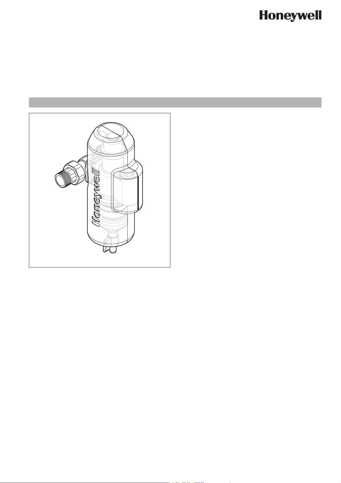
Construction
The sludge and air separator consists of:
•Housing
• Connection piece incl. couplings and seals
• Quick bleeder
• Blind plug including magnetic separator
• Foam insulation jacket
•Ball valve
HF49
Sludge and Air Separator
Product specification sheet
Application
The sludge and air separator serves to separate sludge and air
from the heating system. It is equipped with a sludge and contamination reduction feature that functions according to the
cyclone principle. This guarantees an effective separation of the
particles.
There is an optional phosphate cartridge available to prevent
corrosion in aluminium-free heating systems.
Special Features
• swivel connection for vertical or horizontal installation
• quality insulation shell to prevent heat loss
• integrated quick bleeder
• integrated magnet for separation of ferromagnetic metals
Range of Application
The sludge and air separator is installed in the heating circuit (feed
and return line) and serves to separate sludge and air from the
heater water.
Technical Data
Connection diameter DN25
Nominal pressure (PN) 10 bar
Operating pressure max. 10 bar
Nominal flow 3,6 m³/h
Pressure loss during nominal flow rate 0,2 bar
k
-value 7,8 m³/h
vs
Operating temperature max. 90°C
Materials
• Dezincification resistant brass housing
• Connection piece made of dezincification-resistant brass
• Quick bleeder made of dezincification-resistant brass
• Foam insulation made of PE foam
• EPDM sealing washers
EN0H-1547GE23 R1009 • Subject to change
www.honeywell.com 1
Page 2
HF49 Sludge and Air Separator
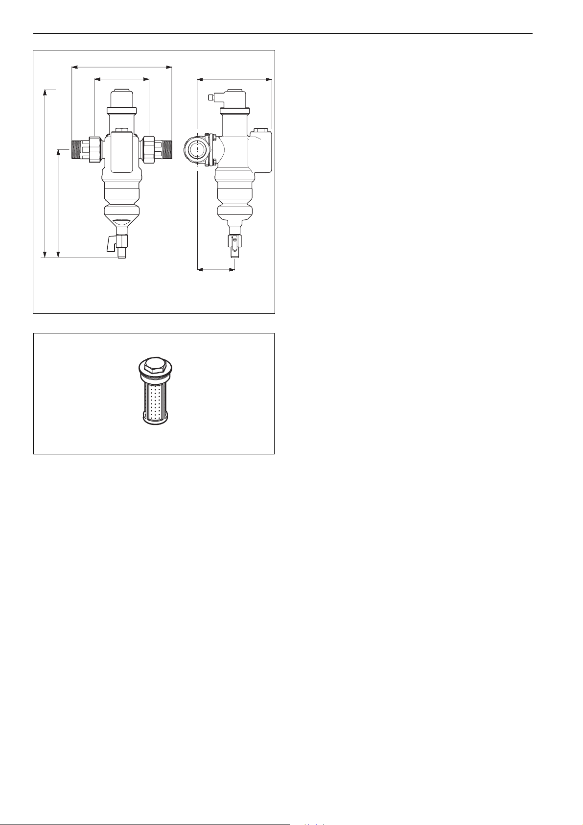
184
100
138
Method of Operation
The heater water separator serves to separate sludge and air
from the heater system.
It is equipped with a sludge and contamination reduction that
functions according to the cyclone principle. This guarantees an
effective separation of the particles.
The heater water separator is equipped with a quick bleeder for
the air separation. If there is air in the system, it will rise to the
highest point of the heater water separator. The water level drops
there, the integrated floater pulls the floater arm down and
330
thereby opens the sealed area. The air bleeds out whereby the
water level rises again and the sealed area is closed again.
310
The optionally available phosphate cartridge counters the corrosion in the heater system. This dosing serves as an additional
protection of the heater system; not as a replacement of the
basic conditioning of the heater water by inhibitors.
Options
70
HF49-1A= Standard version
Accessories
PE49 Phosphate cartridge
Phosphate cartridge for protection of the heater system
against corrosion.
Use only in heater systems without aluminium materials.
PE49
EN0H-1547GE23 R1009 • Subject to change
2 www.honeywell.com
Page 3

Installation examples
HF49 Sludge and Air Separator
HF49 in feed line
Installation Guidelines
• The sludge and air separator is not suited for:
o the separation of oils greases, solvents, soaps and other
lubricating media
o the separation of water-solvent materials
• The sludge and air separator is installed in the heating circuit
(feed and return line)
• The heating system needs to be rinsed and filled
• The national installation regulations, general guidelines and
technical data must be observed during the assembly
• The installation site has to be frost-free and the protection of
the device from chemicals, paints, solvents, vapours and
environmental influences must be guaranteed
• A course dirt separator needs to be installed up front for
water with course dirt particles
• To ensure the bleeding of the air, the sludge and air separator
has to be installed with the quick bleeder upwards
• The separator has to stand vertically; the connection piece
can be built into horizontal and vertical lines
• Make sure the seals fit properly. The pressure-sealing tightening of the screws has to be done cross-wise
• Install stop valves ahead and following the sludge and air
separator
o This makes it possible to maintain the sludge and air sepa-
rator easily without draining the heating system
• Mount the sludge and air separator at easily accessible
points in the system
HF49 in return line
Typical Applications
For installation in the heating circuit to filter out dirt and sludge
particles and bleed off air.
This prevents malfunctions and damage to radiators, valves,
pumps, and heat generators.
A high efficiency is ensured for the whole heating system.
EN0H-1547GE23 R1009 • Subject to change
www.honeywell.com 3
Page 4

HF49 Sludge and Air Separator
1
Spare Parts
Sludge and Air Separator HF49 (from 2008 onwards)
1 Venting insert EE49
2 Ball valve KH49
available as
accessorie
2
Automation and Control Solutions
Honeywell GmbH
Hardhofweg
D-74821 Mosbach
Phone: (49) 6261 810
Fax: (49) 6261 81309
http://europe.hbc.honeywell.com
www.honeywell.com
Manufactured for and on behalf of the
Environmental and Combustion Controls Division
of Honeywell Technologies Sàrl, Rolle, Z.A. La
Pièce 16, Switzerland by its Authorised Representative Honeywell GmbH
EN0H-1547GE23 R1009
Subject to change without notice
© 2009 Honeywell GmbH
 Loading...