

Page 1

HRDV
Digital Video Recorder
Reference Guide
Document 900.0261 – 04/05 – Rev 1.00
Page 2

Page 3

HRDV Reference Guide
Page 4

Revisions
Issue Date Revisions
1.00 03/05 New, rebranded document based on 900.0083.
Page 5

HRDV Reference Guide
Contents
About This Document . . . . . . . . . . . . . . . . . . . . . . . . . . . . . . . . . . . . . . . . . . . . ix
Overview of Contents. . . . . . . . . . . . . . . . . . . . . . . . . . . . . . . . . . . . . . . . . . . . ix
Related Documents . . . . . . . . . . . . . . . . . . . . . . . . . . . . . . . . . . . . . . . . . . . . xi
Important Safeguards and Warnings. . . . . . . . . . . . . . . . . . . . . . . . . . . . . . . . . . . . xi
FCC Compliance . . . . . . . . . . . . . . . . . . . . . . . . . . . . . . . . . . . . . . . . . . . . . . xii
Warranty and Service. . . . . . . . . . . . . . . . . . . . . . . . . . . . . . . . . . . . . . . . . . . xiii
Typographical Conventions . . . . . . . . . . . . . . . . . . . . . . . . . . . . . . . . . . . . . . . xiii
1 Features Overview . . . . . . . . . . . . . . . . . . . . . . . . . . . . . . . . . . . . . . . . . . . 1
HRDV Features . . . . . . . . . . . . . . . . . . . . . . . . . . . . . . . . . . . . . . . . . . . . . . . 1
Remote Access Software Features. . . . . . . . . . . . . . . . . . . . . . . . . . . . . . . . . . . . . 3
2 Controls, LCD Display, and Indicators . . . . . . . . . . . . . . . . . . . . . . . . . . . . . . . . . 5
Control Panel . . . . . . . . . . . . . . . . . . . . . . . . . . . . . . . . . . . . . . . . . . . . . . . . 5
Text Entry Screen. . . . . . . . . . . . . . . . . . . . . . . . . . . . . . . . . . . . . . . . . . . . . . 7
LCD Display . . . . . . . . . . . . . . . . . . . . . . . . . . . . . . . . . . . . . . . . . . . . . . . . 8
Video Monitor Indicators . . . . . . . . . . . . . . . . . . . . . . . . . . . . . . . . . . . . . . . . . . 9
3 System Startup . . . . . . . . . . . . . . . . . . . . . . . . . . . . . . . . . . . . . . . . . . . . 11
System Components . . . . . . . . . . . . . . . . . . . . . . . . . . . . . . . . . . . . . . . . . . . . 11
Performing an Initial System Check . . . . . . . . . . . . . . . . . . . . . . . . . . . . . . . . . . . . 13
Turning On the HRDV the First Time . . . . . . . . . . . . . . . . . . . . . . . . . . . . . . . 13
Rebooting (Restarting) the HRDV . . . . . . . . . . . . . . . . . . . . . . . . . . . . . . . .13
Attaching a Monitor . . . . . . . . . . . . . . . . . . . . . . . . . . . . . . . . . . . . . . . . 13
Setting the HRDV to Factory Defaults . . . . . . . . . . . . . . . . . . . . . . . . . . . . . . 13
Attaching a Camera. . . . . . . . . . . . . . . . . . . . . . . . . . . . . . . . . . . . . . . .14
Initial Installation Mandatory Steps. . . . . . . . . . . . . . . . . . . . . . . . . . . . . . . . . . . . . 14
Connecting the HRDV16/8 to Peripherals . . . . . . . . . . . . . . . . . . . . . . . . . . . . 15
4 Programming Overview. . . . . . . . . . . . . . . . . . . . . . . . . . . . . . . . . . . . . . . . 19
Entering Program Mode . . . . . . . . . . . . . . . . . . . . . . . . . . . . . . . . . . . . . . . . . . 19
Navigating in the Menus . . . . . . . . . . . . . . . . . . . . . . . . . . . . . . . . . . . . . . . . . . 20
Activating Configuration Changes . . . . . . . . . . . . . . . . . . . . . . . . . . . . . . . . . . . . . 21
Exiting Program Mode . . . . . . . . . . . . . . . . . . . . . . . . . . . . . . . . . . . . . . . . . . . 22
Menu Structure . . . . . . . . . . . . . . . . . . . . . . . . . . . . . . . . . . . . . . . . . . . . . . . 22
5 Easy Configurator. . . . . . . . . . . . . . . . . . . . . . . . . . . . . . . . . . . . . . . . . . . 23
Situation . . . . . . . . . . . . . . . . . . . . . . . . . . . . . . . . . . . . . . . . . . . . . . . . . . 23
Setting Up with Easy Configurator . . . . . . . . . . . . . . . . . . . . . . . . . . . . . . . . . . . . . 23
6 User Access . . . . . . . . . . . . . . . . . . . . . . . . . . . . . . . . . . . . . . . . . . . . . . 29
Changing Passwords. . . . . . . . . . . . . . . . . . . . . . . . . . . . . . . . . . . . . . . . . . . . 29
Changing User Names . . . . . . . . . . . . . . . . . . . . . . . . . . . . . . . . . . . . . . . . . . . 31
Rev 1.00 i Document 900.0261
04/05
Page 6

Contents
Setting Permission Levels . . . . . . . . . . . . . . . . . . . . . . . . . . . . . . . . . . . . . . . . . 32
Recovering Administrator Password . . . . . . . . . . . . . . . . . . . . . . . . . . . . . . . . . . . . 32
7 Clock Setup . . . . . . . . . . . . . . . . . . . . . . . . . . . . . . . . . . . . . . . . . . . . . . 33
Changing the Clock Settings . . . . . . . . . . . . . . . . . . . . . . . . . . . . . . . . . . . . . . . . 33
8 Alarm Setup . . . . . . . . . . . . . . . . . . . . . . . . . . . . . . . . . . . . . . . . . . . . . . 35
Setting Alarm Events . . . . . . . . . . . . . . . . . . . . . . . . . . . . . . . . . . . . . . . . . . . .37
Setting Alarm Event Recording Calendar . . . . . . . . . . . . . . . . . . . . . . . . . . . . 38
Alarm Homing . . . . . . . . . . . . . . . . . . . . . . . . . . . . . . . . . . . . . . . . . . . . . . .39
Alarm I/O Connection . . . . . . . . . . . . . . . . . . . . . . . . . . . . . . . . . . . . . . . . . . . 40
9 User Preferences . . . . . . . . . . . . . . . . . . . . . . . . . . . . . . . . . . . . . . . . . . . 43
10 Storage Setup . . . . . . . . . . . . . . . . . . . . . . . . . . . . . . . . . . . . . . . . . . . . . 47
Configuring Storage Setup . . . . . . . . . . . . . . . . . . . . . . . . . . . . . . . . . . . . . . . . . 47
Calculating Disk Space Required . . . . . . . . . . . . . . . . . . . . . . . . . . . . . . . . . . . . . 50
Calculating How Many Hours the Disk Will Record . . . . . . . . . . . . . . . . . . . . . . . . . . . . 51
Calculating Event Space Required. . . . . . . . . . . . . . . . . . . . . . . . . . . . . . . . . . . . . 51
Viewing Current Hard Drive Capacity . . . . . . . . . . . . . . . . . . . . . . . . . . . . . . . . . . . 51
Adding or Replacing a Disk Drive . . . . . . . . . . . . . . . . . . . . . . . . . . . . . . . . . . . . . 52
Data Recovery . . . . . . . . . . . . . . . . . . . . . . . . . . . . . . . . . . . . . . . . . . . . . . . 53
Verify File System. . . . . . . . . . . . . . . . . . . . . . . . . . . . . . . . . . . . . . . . . . . . . .54
Holdup Setup . . . . . . . . . . . . . . . . . . . . . . . . . . . . . . . . . . . . . . . . . . . . . . . . 55
11 Recording Considerations . . . . . . . . . . . . . . . . . . . . . . . . . . . . . . . . . . . . . . 57
Starting and Stopping Recording . . . . . . . . . . . . . . . . . . . . . . . . . . . . . . . . . . . . . 57
Timelapse and Event Recording Considerations . . . . . . . . . . . . . . . . . . . . . . . . . . . . . 58
Event Handling . . . . . . . . . . . . . . . . . . . . . . . . . . . . . . . . . . . . . . . . . . 58
12 Timelapse Recording Setup . . . . . . . . . . . . . . . . . . . . . . . . . . . . . . . . . . . . . 61
Setting Up Simple Timelapse . . . . . . . . . . . . . . . . . . . . . . . . . . . . . . . . . . . . . . . 62
Setting Simple Timelapse Mode With Motion Detect Enabled . . . . . . . . . . . . . . . . . . . . . . 65
Setting Advanced Timelapse Mode . . . . . . . . . . . . . . . . . . . . . . . . . . . . . . . . . . . .68
Setting Recording Times For Holidays. . . . . . . . . . . . . . . . . . . . . . . . . . . . . . . . . . . 74
13 Motion Event Recording Setup . . . . . . . . . . . . . . . . . . . . . . . . . . . . . . . . . . . . 77
Setting Motion Events . . . . . . . . . . . . . . . . . . . . . . . . . . . . . . . . . . . . . . . . . . . 77
Setting Up Motion Zones . . . . . . . . . . . . . . . . . . . . . . . . . . . . . . . . . . . . . 79
Setting Motion Event Recording Calendar . . . . . . . . . . . . . . . . . . . . . . . . . . . . 82
14 Pre-Event Recording Setup. . . . . . . . . . . . . . . . . . . . . . . . . . . . . . . . . . . . . . 83
Recording Timelapse, Pre-Event, and Motion Clips . . . . . . . . . . . . . . . . . . . . . . . . . . . . 85
Recording Only Pre-Event and Motion Event Clips . . . . . . . . . . . . . . . . . . . . . . . . . . . . 87
15 Daily Operation Overview. . . . . . . . . . . . . . . . . . . . . . . . . . . . . . . . . . . . . . . 91
Front Panel Controls . . . . . . . . . . . . . . . . . . . . . . . . . . . . . . . . . . . . . . . . . . . . 91
Live Monitoring . . . . . . . . . . . . . . . . . . . . . . . . . . . . . . . . . . . . . . . . . . . . . . .93
Display Setup . . . . . . . . . . . . . . . . . . . . . . . . . . . . . . . . . . . . . . . . . . . . . . . . 94
Setting the Display Operation . . . . . . . . . . . . . . . . . . . . . . . . . . . . . . . . . . . . . . . 95
Setting the Main Monitor Display . . . . . . . . . . . . . . . . . . . . . . . . . . . . . . . . .95
Setting the Spot Monitor Display . . . . . . . . . . . . . . . . . . . . . . . . . . . . . . . . .97
Configuring Covert Setup. . . . . . . . . . . . . . . . . . . . . . . . . . . . . . . . . . . . . 97
Configuring the Video Inputs . . . . . . . . . . . . . . . . . . . . . . . . . . . . . . . . . . . . . . . . 98
Sequencing Mode . . . . . . . . . . . . . . . . . . . . . . . . . . . . . . . . . . . . . . . 100
Rev 1.00 ii Document 900.0261
04/05
Page 7

HRDV Reference Guide
16 Video Playback and Searching . . . . . . . . . . . . . . . . . . . . . . . . . . . . . . . . . . . .103
Using the Autoplay Function . . . . . . . . . . . . . . . . . . . . . . . . . . . . . . . . . . . . . . . 103
Playing Back Recorded Clips . . . . . . . . . . . . . . . . . . . . . . . . . . . . . . . . . . . . . . 104
Searching for Video Clips with the Go To Search Screen . . . . . . . . . . . . . . . . . . . . . . . . 105
Searching for Video Clips to Play Back . . . . . . . . . . . . . . . . . . . . . . . . . . . . . . . . . 107
Playing Video Clips . . . . . . . . . . . . . . . . . . . . . . . . . . . . . . . . . . . . . . . . . . . . 109
Lock to One Camera . . . . . . . . . . . . . . . . . . . . . . . . . . . . . . . . . . . . . . . . . . . 110
Autobreak. . . . . . . . . . . . . . . . . . . . . . . . . . . . . . . . . . . . . . . . . . . . . . . . . 110
17 Report Generation . . . . . . . . . . . . . . . . . . . . . . . . . . . . . . . . . . . . . . . . . .113
Using the Reports Menu . . . . . . . . . . . . . . . . . . . . . . . . . . . . . . . . . . . . . . . . . 113
Creating a Report . . . . . . . . . . . . . . . . . . . . . . . . . . . . . . . . . . . . . . . . 114
Running a Report . . . . . . . . . . . . . . . . . . . . . . . . . . . . . . . . . . . . . . . . 120
Playing Video Clips in a Report. . . . . . . . . . . . . . . . . . . . . . . . . . . . . . . . . 121
Setting Reports to Run Automatically . . . . . . . . . . . . . . . . . . . . . . . . . . . . . 122
Using the Quick Report Function . . . . . . . . . . . . . . . . . . . . . . . . . . . . . . . . . . . . 123
Running an Existing Report . . . . . . . . . . . . . . . . . . . . . . . . . . . . . . . . . . . . . . . 124
Editing a Report . . . . . . . . . . . . . . . . . . . . . . . . . . . . . . . . . . . . . . . . . . . . . 125
Deleting a Report . . . . . . . . . . . . . . . . . . . . . . . . . . . . . . . . . . . . . . . . . . . . . 125
18 Archive Operation. . . . . . . . . . . . . . . . . . . . . . . . . . . . . . . . . . . . . . . . . . .127
Saving Clips to a CD-ROM Drive . . . . . . . . . . . . . . . . . . . . . . . . . . . . . . . . . . . . . 127
Saving Video Clips to an Archive Drive . . . . . . . . . . . . . . . . . . . . . . . . . . . . . . . . . 132
Archiving Clips to a Removable Drive . . . . . . . . . . . . . . . . . . . . . . . . . . . . . . . . . . 133
Hot Swapping the Removable Drive . . . . . . . . . . . . . . . . . . . . . . . . . . . . . . . . . . . 133
Archiving Images to a VCR . . . . . . . . . . . . . . . . . . . . . . . . . . . . . . . . . . . . . . . . 134
Format the Archive Drive . . . . . . . . . . . . . . . . . . . . . . . . . . . . . . . . . . . . . . . . . 134
19 Networking on Ethernet. . . . . . . . . . . . . . . . . . . . . . . . . . . . . . . . . . . . . . . .135
Enabling Remote Access. . . . . . . . . . . . . . . . . . . . . . . . . . . . . . . . . . . . . . . . . 135
Installing an 10/100BaseT Network PCMCIA Card . . . . . . . . . . . . . . . . . . . . . . . . . . . 138
Setting Bandwidth Throttle on the HRDV8/16 . . . . . . . . . . . . . . . . . . . . . . . . . 138
User Definable TCP Port Number for RAS . . . . . . . . . . . . . . . . . . . . . . . . . . . 139
20 Text . . . . . . . . . . . . . . . . . . . . . . . . . . . . . . . . . . . . . . . . . . . . . . . . . .143
Step 1. Set Up Text Ports. . . . . . . . . . . . . . . . . . . . . . . . . . . . . . . . . . . . . . . . . 143
Step 2. Configure the Video Inputs. . . . . . . . . . . . . . . . . . . . . . . . . . . . . . . . . . . . 145
Step 3. Set Text Events. . . . . . . . . . . . . . . . . . . . . . . . . . . . . . . . . . . . . . . . . . 146
Step 4. Set Trigger Text Strings . . . . . . . . . . . . . . . . . . . . . . . . . . . . . . . . . . . . . 147
Step 5. Set Text Event Recording Calendar . . . . . . . . . . . . . . . . . . . . . . . . . . . . . . . 148
Setting up Point of Sale and Cash Register Interface . . . . . . . . . . . . . . . . . . . . . . . . . . 149
Setting Wayne (Dresser) Nucleus POS Cash Register Interface . . . . . . . . . . . . . . . 152
Setting Generic Cash Register Interface For On-site Cash Register and POS
Server Programming . . . . . . . . . . . . . . . . . . . . . . . . . . . . . . . . . . . . . . 153
21 Pan, Tilt, Zoom (PTZ) . . . . . . . . . . . . . . . . . . . . . . . . . . . . . . . . . . . . . . . . .155
Controlling PTZ Camera Operation . . . . . . . . . . . . . . . . . . . . . . . . . . . . . . . . . . . 156
22 Evidence CD. . . . . . . . . . . . . . . . . . . . . . . . . . . . . . . . . . . . . . . . . . . . . .159
Locating Video to Save . . . . . . . . . . . . . . . . . . . . . . . . . . . . . . . . . . . . . . . . . . 159
Providing Evidence to a Third Party . . . . . . . . . . . . . . . . . . . . . . . . . . . . . . . . . . . 160
Viewing the Video Evidence . . . . . . . . . . . . . . . . . . . . . . . . . . . . . . . . . . . . . . . 160
Authenticating Images on the Evidence CD . . . . . . . . . . . . . . . . . . . . . . . . . . . . . . . 161
Compatible PC Operating Systems . . . . . . . . . . . . . . . . . . . . . . . . . . . . . . . . . . . 162
Rev 1.00 iii Document 900.0261
04/05
Page 8

Contents
23 Video Authentication . . . . . . . . . . . . . . . . . . . . . . . . . . . . . . . . . . . . . . . . .163
HRDV Recorded Video Format. . . . . . . . . . . . . . . . . . . . . . . . . . . . . . . . . . . . . . 163
Obtaining the Secret Key. . . . . . . . . . . . . . . . . . . . . . . . . . . . . . . . . . . . . . . . . 163
Authenticating the Image . . . . . . . . . . . . . . . . . . . . . . . . . . . . . . . . . . . . . . . . . 164
Appendix A E-Mail Alert Program Installation . . . . . . . . . . . . . . . . . . . . . . . . . . . .165
Configuring Alarm and E-Mail Notification Over TCP/IP . . . . . . . . . . . . . . . . . . . . . . . . . 165
Installing the E-Mail Alert Program . . . . . . . . . . . . . . . . . . . . . . . . . . . . . . . . . . . . 167
Appendix B POS Interface. . . . . . . . . . . . . . . . . . . . . . . . . . . . . . . . . . . . . . .173
Determining the Generic TEXT Protocol Setup Required For a POS Server or Cash Register . . . . . 174
Interpretation of POS Data For Programming . . . . . . . . . . . . . . . . . . . . . . . . . . . . . . 175
Interpretation of POS data for programming. . . . . . . . . . . . . . . . . . . . . . . . . . . . . . . 177
Hexadecimal to ASCII Conversion . . . . . . . . . . . . . . . . . . . . . . . . . . . . . . . . . . . . 181
Control Character Codes. . . . . . . . . . . . . . . . . . . . . . . . . . . . . . . . . . . . . . . . . 181
Appendix C Maintenance . . . . . . . . . . . . . . . . . . . . . . . . . . . . . . . . . . . . . . .183
Viewing System Information . . . . . . . . . . . . . . . . . . . . . . . . . . . . . . . . . . . . . . . 183
Viewing System Log Information . . . . . . . . . . . . . . . . . . . . . . . . . . . . . . . . . . . . . 184
Software Update . . . . . . . . . . . . . . . . . . . . . . . . . . . . . . . . . . . . . . . . . . . . . 185
Downloading Software Using the CD-ROM Drive . . . . . . . . . . . . . . . . . . . . . . . 185
Downloading Software Using RAS . . . . . . . . . . . . . . . . . . . . . . . . . . . . . . . 186
Windows Com Port Speed . . . . . . . . . . . . . . . . . . . . . . . . . . . . . . . . . . . 187
Installing the SUU. . . . . . . . . . . . . . . . . . . . . . . . . . . . . . . . . . . . . . . . 188
Attaching the SUU Cable . . . . . . . . . . . . . . . . . . . . . . . . . . . . . . . . . . . . 188
Downloading Software Using SUU . . . . . . . . . . . . . . . . . . . . . . . . . . . . . . . 188
Setting up the HRDV16/8 . . . . . . . . . . . . . . . . . . . . . . . . . . . . . . . . . . . . 189
Appendix D Installation Scenarios . . . . . . . . . . . . . . . . . . . . . . . . . . . . . . . . . .191
Appendix E Solutions . . . . . . . . . . . . . . . . . . . . . . . . . . . . . . . . . . . . . . . . .195
Appendix F S.M.A.R.T.. . . . . . . . . . . . . . . . . . . . . . . . . . . . . . . . . . . . . . . . .197
Appendix G Video Formats and Digital Video . . . . . . . . . . . . . . . . . . . . . . . . . . . .201
Frames and Fields . . . . . . . . . . . . . . . . . . . . . . . . . . . . . . . . . . . . . . . . . . . . 201
NTSC and PAL . . . . . . . . . . . . . . . . . . . . . . . . . . . . . . . . . . . . . . . . . . . . . . 201
Composite Video and S-Video . . . . . . . . . . . . . . . . . . . . . . . . . . . . . . . . . . . . . . 202
Hard Disk Speed—Throughput . . . . . . . . . . . . . . . . . . . . . . . . . . . . . . . . . . . . . 203
Compression . . . . . . . . . . . . . . . . . . . . . . . . . . . . . . . . . . . . . . . . . . . . . . . 203
Compression Ratio and Recording Times . . . . . . . . . . . . . . . . . . . . . . . . . . . 204
Wavelet Compression . . . . . . . . . . . . . . . . . . . . . . . . . . . . . . . . . . . . . 204
Audio Compression. . . . . . . . . . . . . . . . . . . . . . . . . . . . . . . . . . . . . . . 204
Appendix H Specifications and Pinouts . . . . . . . . . . . . . . . . . . . . . . . . . . . . . . .205
Specifications. . . . . . . . . . . . . . . . . . . . . . . . . . . . . . . . . . . . . . . . . . . . . . . 205
Pinouts . . . . . . . . . . . . . . . . . . . . . . . . . . . . . . . . . . . . . . . . . . . . . . . . . . 207
HRDV DB25 to a PC COM Port for Remote Access Software (RAS) . . . . . . . . . . . . . 207
25-Pin COM Connector Pinouts . . . . . . . . . . . . . . . . . . . . . . . . . . . . . . . . 208
Remote Key Pad Operation . . . . . . . . . . . . . . . . . . . . . . . . . . . . . . . . . . 209
Glossary . . . . . . . . . . . . . . . . . . . . . . . . . . . . . . . . . . . . . . . . . . . . . . . . . . 211
Index . . . . . . . . . . . . . . . . . . . . . . . . . . . . . . . . . . . . . . . . . . . . . . . . . . . . . . 1
Rev 1.00 iv Document 900.0261
04/05
Page 9

HRDV Reference Guide
Figures
Figure 2-1 Video Monitor Indicators. . . . . . . . . . . . . . . . . . . . . . . . . . . . . . . . . . . . . 9
Figure 3-1 Rear Panel Connections (HRDV16 Shown) . . . . . . . . . . . . . . . . . . . . . . . . . . 16
Figure 4-1 Main Menu . . . . . . . . . . . . . . . . . . . . . . . . . . . . . . . . . . . . . . . . . . . 20
Figure 4-2 Text Entry Screen . . . . . . . . . . . . . . . . . . . . . . . . . . . . . . . . . . . . . . . 21
Figure 4-3 HRDV16/8 Menu Tree . . . . . . . . . . . . . . . . . . . . . . . . . . . . . . . . . . . . . 22
Figure 5-1 Initial Easy Configurator Screen . . . . . . . . . . . . . . . . . . . . . . . . . . . . . . . . 23
Figure 5-2 Easy Config Menu Screen . . . . . . . . . . . . . . . . . . . . . . . . . . . . . . . . . . . 24
Figure 5-3 Video Setup Screen . . . . . . . . . . . . . . . . . . . . . . . . . . . . . . . . . . . . . . 24
Figure 5-4 Timelapse Recording Setup Screen. . . . . . . . . . . . . . . . . . . . . . . . . . . . . . 25
Figure 5-5 Disk Setup Screen . . . . . . . . . . . . . . . . . . . . . . . . . . . . . . . . . . . . . . . 25
Figure 5-6 Text Event Setup Screen . . . . . . . . . . . . . . . . . . . . . . . . . . . . . . . . . . . 26
Figure 5-7 Motion Event Setup Screen . . . . . . . . . . . . . . . . . . . . . . . . . . . . . . . . . . 26
Figure 5-8 Alarm Event Setup Screen. . . . . . . . . . . . . . . . . . . . . . . . . . . . . . . . . . . 27
Figure 5-9 Remote Access Setup Screen. . . . . . . . . . . . . . . . . . . . . . . . . . . . . . . . . 27
Figure 6-1 Select a User Screen . . . . . . . . . . . . . . . . . . . . . . . . . . . . . . . . . . . . . 30
Figure 6-2 User Permissions Screen . . . . . . . . . . . . . . . . . . . . . . . . . . . . . . . . . . . 31
Figure 7-1 Clock Setup Screen . . . . . . . . . . . . . . . . . . . . . . . . . . . . . . . . . . . . . . 33
Figure 8-1 General Setup Screen . . . . . . . . . . . . . . . . . . . . . . . . . . . . . . . . . . . . . 35
Figure 8-2 Alarm Event Setup Screen. . . . . . . . . . . . . . . . . . . . . . . . . . . . . . . . . . . 37
Figure 8-3 Alarm Event Calendar Screen . . . . . . . . . . . . . . . . . . . . . . . . . . . . . . . . . 38
Figure 9-1 User Preferences Screen . . . . . . . . . . . . . . . . . . . . . . . . . . . . . . . . . . . 43
Figure 10-1 Disk Menu . . . . . . . . . . . . . . . . . . . . . . . . . . . . . . . . . . . . . . . . . . . 48
Figure 10-2 Disk Setup Screen . . . . . . . . . . . . . . . . . . . . . . . . . . . . . . . . . . . . . . . 48
Figure 10-3 Disk Status Screen. . . . . . . . . . . . . . . . . . . . . . . . . . . . . . . . . . . . . . . 52
Figure 10-4 Data Recovery Screen . . . . . . . . . . . . . . . . . . . . . . . . . . . . . . . . . . . . . 53
Figure 10-5 FileSystem Verify Screen . . . . . . . . . . . . . . . . . . . . . . . . . . . . . . . . . . . 54
Figure 10-6 Holdup Setup Screen . . . . . . . . . . . . . . . . . . . . . . . . . . . . . . . . . . . . . 55
Figure 12-1 Timelapse Recording Screen . . . . . . . . . . . . . . . . . . . . . . . . . . . . . . . . . 62
Figure 12-2 Timelapse in Simple Mode . . . . . . . . . . . . . . . . . . . . . . . . . . . . . . . . . . 64
Figure 12-3 Typical Advanced Recording Schedule Setup . . . . . . . . . . . . . . . . . . . . . . . . 69
Figure 12-4 Timelapse Global Rate Examples . . . . . . . . . . . . . . . . . . . . . . . . . . . . . . . 70
Figure 12-5 Timelapse with Motion Mode in Advanced Mode . . . . . . . . . . . . . . . . . . . . . . . 74
Figure 12-6 Holiday Setup Screen . . . . . . . . . . . . . . . . . . . . . . . . . . . . . . . . . . . . . 74
Figure 13-1 Motion Event Setup Screen . . . . . . . . . . . . . . . . . . . . . . . . . . . . . . . . . . 78
Figure 13-2 Zone Layout Screen per Camera . . . . . . . . . . . . . . . . . . . . . . . . . . . . . . . 79
Rev 1.00 v Document 900.0261
04/05
Page 10

Figures
Figure 13-3 Motion Event Calendar Screen . . . . . . . . . . . . . . . . . . . . . . . . . . . . . . . . 82
Figure 14-1 Pre-event Setup Screen . . . . . . . . . . . . . . . . . . . . . . . . . . . . . . . . . . . . 84
Figure 14-2 Recorded Review Clips List, All Types Shown . . . . . . . . . . . . . . . . . . . . . . . . 87
Figure 14-3 Recorded Review Clips List, Pre-Event and Motion Shown. . . . . . . . . . . . . . . . . . 89
Figure 15-1 Front Panel . . . . . . . . . . . . . . . . . . . . . . . . . . . . . . . . . . . . . . . . . . 91
Figure 15-2 Live Monitoring Examples . . . . . . . . . . . . . . . . . . . . . . . . . . . . . . . . . . . 94
Figure 15-3 Display Setup Screen . . . . . . . . . . . . . . . . . . . . . . . . . . . . . . . . . . . . . 95
Figure 15-4 Main Monitor Screen. . . . . . . . . . . . . . . . . . . . . . . . . . . . . . . . . . . . . . 96
Figure 15-5 Spot Monitor Screen . . . . . . . . . . . . . . . . . . . . . . . . . . . . . . . . . . . . . . 97
Figure 15-6 Covert Setup Screen. . . . . . . . . . . . . . . . . . . . . . . . . . . . . . . . . . . . . . 98
Figure 15-7 Camera (Video) Setup Screen. . . . . . . . . . . . . . . . . . . . . . . . . . . . . . . . . 98
Figure 16-1 Go To Search Screen . . . . . . . . . . . . . . . . . . . . . . . . . . . . . . . . . . . . 105
Figure 16-2 Search Screen . . . . . . . . . . . . . . . . . . . . . . . . . . . . . . . . . . . . . . . . 107
Figure 17-1 Reports Main Menu . . . . . . . . . . . . . . . . . . . . . . . . . . . . . . . . . . . . . 114
Figure 17-2 Create New Report Screen . . . . . . . . . . . . . . . . . . . . . . . . . . . . . . . . . 114
Figure 17-3 Text Criteria Screen . . . . . . . . . . . . . . . . . . . . . . . . . . . . . . . . . . . . . 116
Figure 17-4 Event Criteria Setup Screen . . . . . . . . . . . . . . . . . . . . . . . . . . . . . . . . . 118
Figure 17-5 Report Zone Layout Screen . . . . . . . . . . . . . . . . . . . . . . . . . . . . . . . . . 119
Figure 17-6 Run A Report Screen . . . . . . . . . . . . . . . . . . . . . . . . . . . . . . . . . . . . 120
Figure 17-7 Setup a Report to Run Automatically Screen . . . . . . . . . . . . . . . . . . . . . . . . 123
Figure 18-1 Archive Camera Selection . . . . . . . . . . . . . . . . . . . . . . . . . . . . . . . . . . 129
Figure 18-2 Archive Camera Selection . . . . . . . . . . . . . . . . . . . . . . . . . . . . . . . . . . 132
Figure 19-1 Remote Access Screen . . . . . . . . . . . . . . . . . . . . . . . . . . . . . . . . . . . 136
Figure 19-2 User Preferences Screen . . . . . . . . . . . . . . . . . . . . . . . . . . . . . . . . . . 139
Figure 19-3 Sample Multiple HRDV Units, One Common IP Address . . . . . . . . . . . . . . . . . . 140
Figure 19-4 Network Connection Screen. . . . . . . . . . . . . . . . . . . . . . . . . . . . . . . . . 140
Figure 20-1 Text Ports Screen . . . . . . . . . . . . . . . . . . . . . . . . . . . . . . . . . . . . . . 144
Figure 20-2 Camera (Video) Setup Screen. . . . . . . . . . . . . . . . . . . . . . . . . . . . . . . . 145
Figure 20-3 Text Event Setup Screen . . . . . . . . . . . . . . . . . . . . . . . . . . . . . . . . . . 147
Figure 20-4 Enter Trigger Text - Port 1 . . . . . . . . . . . . . . . . . . . . . . . . . . . . . . . . . . 148
Figure 20-5 Text Event Calendar Screen . . . . . . . . . . . . . . . . . . . . . . . . . . . . . . . . . 149
Figure A-1 Advanced Remote Setup Screen . . . . . . . . . . . . . . . . . . . . . . . . . . . . . . 166
Figure C-1 System Information Screen . . . . . . . . . . . . . . . . . . . . . . . . . . . . . . . . . 183
Figure C-2 System Log Screen . . . . . . . . . . . . . . . . . . . . . . . . . . . . . . . . . . . . . 184
Figure C-3 CD Contents with Firmware File . . . . . . . . . . . . . . . . . . . . . . . . . . . . . . . 186
Figure C-4 Select Download Type Screen . . . . . . . . . . . . . . . . . . . . . . . . . . . . . . . 186
Figure C-5 Confirm Download Screen. . . . . . . . . . . . . . . . . . . . . . . . . . . . . . . . . . 186
Figure C-6 Download Software Screen . . . . . . . . . . . . . . . . . . . . . . . . . . . . . . . . . 187
Figure D-1 TCP/IP Ethernet Network . . . . . . . . . . . . . . . . . . . . . . . . . . . . . . . . . . 192
Figure D-2 Telco or LAN Network . . . . . . . . . . . . . . . . . . . . . . . . . . . . . . . . . . . . 193
Figure H-1 DB25 to PC COM Port Pinouts . . . . . . . . . . . . . . . . . . . . . . . . . . . . . . . 208
Rev 1.00 vi Document 900.0261
04/05
Page 11

HRDV Reference Guide
Tables
Table 2-1 Front Panel Menu Navigation Controls . . . . . . . . . . . . . . . . . . . . . . . . . . . . . . 6
Table 2-2 Video Monitor Control Buttons . . . . . . . . . . . . . . . . . . . . . . . . . . . . . . . . . . 9
Table 2-3 Video Monitor Record Indicators . . . . . . . . . . . . . . . . . . . . . . . . . . . . . . . . 10
Table 3-1 Rear Panel Connections . . . . . . . . . . . . . . . . . . . . . . . . . . . . . . . . . . . . 16
Table 15-1 Front Panel Function Controls . . . . . . . . . . . . . . . . . . . . . . . . . . . . . . . . . 92
Table 16-1 Video Monitor Control Buttons . . . . . . . . . . . . . . . . . . . . . . . . . . . . . . . . 109
Table A-1 Advanced Remote and Email Setup . . . . . . . . . . . . . . . . . . . . . . . . . . . . . 166
Table B-1 Hex to ASCII Conversion Chart. . . . . . . . . . . . . . . . . . . . . . . . . . . . . . . . 181
Table F-1 SMART Attributes . . . . . . . . . . . . . . . . . . . . . . . . . . . . . . . . . . . . . . . 198
Table H-1 Technical Specifications . . . . . . . . . . . . . . . . . . . . . . . . . . . . . . . . . . . 205
Table H-2 Keyboard Functions . . . . . . . . . . . . . . . . . . . . . . . . . . . . . . . . . . . . . 209
Rev 1.00 vii Document 900.0261
04/05
Page 12

Tables
Rev 1.00 viii Document 900.0261
04/05
Page 13

About This Document
This document introduces the HRDV Digital Video Recorder (HRDV16 and HRDV8) and
describes how to install and operate the HRDV16/8.
The information in this document applies to both the HRDV16 and the HRDV8. The
HRDV16 supports 60 fps shared across 16 video channel inputs. The HRDV8 supports 30
fps shared across 8 video channel inputs.
Note The HRDV16 and HRDV8 are referred to as the HRDV16/8 throughout this
guide.
HRDV Reference Guide
Overview of Contents
This document contains the following chapters and appendixes:
• Chapter 1, Features Overview, introduces the HRDV16/8 and its functions and
features.
• Chapter 2, Controls, LCD Display, and Indicators, provides an overview of the front
panel control buttons and describes how to use them to navigate through the
menus. It also describes the LCD display and video monitor indicators.
• Chapter 3, System Startup, shows the rear panel connections and tells you how to
connect the HRDV16/8 to peripheral equipment.
• Chapter 4, Programming Overview, describes how to perform system-wide
configuration settings.
• Chapter 5, Easy Configurator, describes how to perform the Easy Configurator setup
of your recorder in ten minutes or less.
• Chapter 6, User Access, tells you how to change and reset passwords, change user
names, and set permission levels.
• Chapter 7, Clock Setup, describes how to set the system date and time for your
regional preference and enable Daylight Saving time and text insertion
synchronization.
Rev 1.00 900.0261
ix
04/05
Page 14

About This Document
• Chapter 8, Alarm Setup, shows how to set how the HRDV16/8 responds to alarm
events.
• Chapter 9, User Preferences, describes how to set overall system level
configuration, including basic hardware connected to your HRDV16/8.
• Chapter 10, Storage Setup, provides guidelines for calculating required disk storage
space and tells you how to configure your storage setup.
• Chapter 11, Recording Considerations, describes how to use your HRDV16/8 as a
duplex recorder to record timelapse and event video.
• Chapter 12, Timelapse Recording Setup, describes how to schedule your HRDV to
store timelapse clips.
• Chapter 13, Motion Event Recording Setup, shows how to configure your HRDV to
respond to external events.
• Chapter 14, Pre-Event Recording Setup, provides instructions for using the
HRDV16/8 as an event recorder only.
• Chapter 15, Daily Operation Overview, shows how the HRDV16/8 front panel
operates and describes the system configuration menus.
• Chapter 16, Video Playback and Searching, tells you how to play back video clips
from the front panel, as well as using the Reports and Search functions.
• Chapter 17, Report Generation, provides instructions for creating reports based on
text and events. It also describes how to edit, delete, run, automatically schedule
reports, print images from a report, and archive (copy) images in a report to a disk.
• Chapter 18, Archive Operation, describes how to save (copy) clips or images to a
CD-ROM drive, removable drive, or to a VCR.
• Chapter 19, Networking on Ethernet, covers how to set up network connectivity.
• Chapter 20, Text, provides instructions for setting up the four text insertion ports to
interface with POS and cash registers.
• Chapter 21, Pan, Tilt, Zoom (PTZ), describes how to use PTZ control on the HRDV.
• Chapter 22, Evidence CD, covers how to make an evidence CD for authorities.
• Chapter 23, Video Authentication, covers how to authenticate images recorded on
an HRDV using a remote PC running Remote Access Software (RAS).
• Appendix A, E-Mail Alert Program Installation, describes how to install and configure
the E-Mail Alert utility on your PC.
• Appendix B, POS Interface, shows you how to set up an HRDV generic cash register
interface for on-site programming of cash registers and POS servers.
• Appendix C, Maintenance, provides installation procedures for installing the
Software Update Utility on your PC.
• Appendix D, Installation Scenarios, shows typical system installation configurations.
• Appendix E, Solutions, lists typical technical issues and how to solve them.
• Appendix F, S.M.A.R.T., describes the Self-Monitoring Analysis & Reporting
Technology interface between the HRDV and the hard disk.
• Appendix G, Video Formats and Digital Video, provides background information on
frames and fields, NTSC and PAL formats, and explains how compression works.
• Appendix H, Specifications and Pinouts, lists technical specifications for the
HRDV16/8 and provides pinouts for the null modem cable and the DB25 connector.
• Glossary, provides a quick reference for terms used throughout this guide.
Rev 1.00 900.0261
x
04/05
Page 15
Related Documents
For more information about topics that are relevant to the subject of this manual, see the
documents listed below.
Document title Part number
HRDV16/8 Common Operating Procedures 900.0371
HRDV Quick Installation 900.0262
HRDV RAS User Guide 900.0279
HRDV Reference Guide
Internal Drive Upgrade Kit for HRDV16/8 (DV16/8-DUK)
Application Note
HRDV16/8 Internal Drive Upgrade Guide 900.0274
HRDV16/8 Hard Disk Drive Compatibility Product Bulletin D001239
HRDV Network Card and Dial-up Modem Card Compatibility
Product Bulletin
Important Safeguards and Warnings
Caution The installation of this equipment should be made only by qualified
technicians and should conform to all local codes.
You should not remove the cover of your HRDV16/8.
D001186
D001327
RISK OF ELECTRIC
SHOCK
DO NOT OPEN
If your HRDV requires repair, contact Honeywell (see Warranty and Service).
WARNING! The HRDV16/8 is intended for indoor use. To reduce a risk
of fire or electric shock, do not expose this product to rain
or moisture.
Rev 1.00 900.0261
xi
04/05
Page 16

About This Document
FCC Compliance
Information to the User
This equipment has been tested and found to comply with the limits for a Class A digital
device, pursuant to Part 15 of the FCC Rules. These limits are designed to provide
reasonable protection against harmful interference when the equipment is operated in a
commercial environment. This equipment generates, uses, and can radiate radio
frequency energy and, if not installed and used in accordance with the instruction manual,
may cause harmful interference to radio communications. Operation of this equipment in
a residential area is likely to cause harmful interference in which case the user will be
required to correct the interference at his own expense.
Caution Changes or modifications not expressly approved by the party
responsible for compliance could void the user’s authority to
operate the equipment.
This Class A digital apparatus complies with Canadian ICES-003.
Cet appareil numérique de la Classe A est conforme à la norme NMB-003 du Canada.
Rev 1.00 900.0261
xii
04/05
Page 17

Warranty and Service
Subject to the terms and conditions listed on the Product Warranty Card, during the
warranty period Honeywell will repair or replace, at its sole option, free of charge, any
defective products returned prepaid.
In the event you have a problem with any Honeywell product, please call Customer
Service for assistance or to request a Return Merchandise Authorization (RMA) number.
Call Technical Support at 1.800.796.CCTV, option 2.
Be sure to have the model number, serial number, and the nature of the problem outlined
for the technical service representative.
Prior authorization must be obtained for all returns, exchanges, or credits. Items shipped
to Honeywell without a clearly identified Return Merchandise Authorization (RMA) number
may be refused.
HRDV Reference Guide
Typographical Conventions
This document uses the following typographical conventions:
Font What it represents Example
Lucida Values of editable fields that are mentioned in the
body text of the document for reference purposes,
but do not need to be entered as part of a
procedure
Text strings displayed on the screen The message Exit this menu
Lucida Bold Words or characters that you must type. The word
“enter” is used if you must type text and then press
the Enter key.
Values of editable fields that appear in tables (on
first mention)
Swiss721
BT Bold
Menu titles and other items you select Select the Setup menu.
Buttons you click/press to perform actions Click Exit to close the program.
The Daylight Savings Time field can be set
to North America.
displays.
Enter the password:
1234
The Change telnet config password field
can be set to one of the following values:
Yes
No
Italic Placeholders: words that vary depending on the
situation
Cross-reference to external source Refer to the HRDV User Guide.
Cross-reference within document See Overview.
Rev 1.00 900.0261
xiii
Enter the basic parameters.
04/05
Page 18

About This Document
Rev 1.00 900.0261
xiv
04/05
Page 19

Features Overview
The HRDV Digital Video Recorder (HRDV16 and HRDV8) is the heart of your integrated
security solution. The HRDV16/8 combines the following functions:
• Digital video recorder
• Timelapse VCR/event recorder
• 16-channel multiplexer (HRDV8 has an 8-channel multiplexer)
• Video motion detector
• Text inserter (four serial ports)
• Remote video transmission system
• Evidence CD with Viewer
HRDV Features
1
The HRDV16/8 features include:
• Traditional timelapse VCR recording function
• Video motion detection
• Easy HRDV configuration mode
• Go to search function lets you preview video immediately after changing date, time
and camera values
• Go To function:
If Timelapse is selected and a Go To performed, you can play back video like one
big VCR tape without having to jump from clip to clip.
If Event is selected and a Go To performed, you may only be able to play back
video from within a single, short video clip.
• QNX real time operating system
• HRDV firmware stored in flash memory for an easy upgrade that can be done locally
or remotely
• Multiplexed video from up to16 video sources (8 for HRDV8) with multiscreen
display
• Duplex operation allows local reviewing without interrupting recording
• Inserts transaction text information from ATM or POS terminals (generic cash
register interface, for example)
• Remote network or modem connection
• Graphical on-screen Programming mode
Rev 1.00 1 Document 900.0261
04/05
Page 20

Features Overview
• Flexible settings for complete customization
• Upgradable hard drives offer multiple archiving and extended storage options
• Improved text and motion searching in reports
• Playing raw video with or without text data
• Enhanced search features (motion searching, for example)
• Covert monitor setup option
• Local multiple language support
• Bandwidth throttle control support (1 to 250 KBps)
• 10/100BaseT network interface support
• Stop recording alarm
• Single CD with embedded viewer for authorities
• Alarm and e-mail notification over TCP/IP
• Single IP addresses for multiple HRDV units
• Adjustable Ethernet packet size
• Simultaneous live and remote viewing
• 200/250 GB IDE drive support
• Configurable auto delete
• Playback lock to one camera
• Automatic switch to live camera on alarm
• Administrator password recovery
• Auto record after 60 seconds
• Timelapse search options— Autobreak hourly and daily
• Play currently recording video in Turbo mode
• Autoplay enhanced
• Disk drive data recovery utility
®
• Pan, Tilt, and Zoom (local) control for Pelco
D, Kalatel® Cyberdome and VCL
protocols. This feature is available remotely using Remote Access Software (RAS) as
well as locally via the HRDV front panel.
Rev 1.00 2 Document 900.0261
04/05
Page 21

Remote Access Software Features
The HRDV16 uses Remote Access Software (RAS). RAS allows you to perform all functions
remotely that can be performed locally. RAS features include:
• Remote system configuration
• Remotely monitoring your staff
• Extract video from the local unit for a fraud investigation being completed in another
location
• Create and run reports without stopping the HRDV16/8 from recording
• Archive a video clip or individual image to the archive device in the HRDV16/8 or to
the PC
• Print a stored .bmp or .jpg image file directly from RAS
• Use RAS Viewer to read CD-ROMs
• Upgrade your firmware without disturbing system settings
• Optimized RAS/HRDV protocol increases the refresh rate for live viewing and
playback
• Audio support for live monitoring
• Support for HRDV16, HRDV8
• Multiple RAS user access
• PTZ camera support (Pelco D, Kalatel Cyberdome, and VCL)
• Encrypted remote password management support
• User definable TCP port number
• Adjustable live display quality to speed up live images per second
• Live view refresh rate increased in multiscreen view
• RAS multiple playback speeds (x4 to x32)
• Improved ethernet network bandwidth utilization
HRDV Reference Guide
For complete information on HRDV RAS operation and new RAS features, please refer to
the HRDV RAS User Guide.
Rev 1.00 3 Document 900.0261
04/05
Page 22

Features Overview
Rev 1.00 4 Document 900.0261
04/05
Page 23

Controls, LCD Display, and Indicators
This chapter explains:
• The HRDV front panel control buttons you use to navigate through the screens and
make configuration changes
• The HRDV front panel LCD displays
• The video monitor indicators
Control Panel
For onsite security personnel or administrator, the HRDV16/8 front panel keyboard is the
primary user interface for the system. It allows overall control of:
• What is displayed through the monitor
• Whether live or previously recorded video is displayed
• Adjusting the configuration settings to adapt to changing requirements of the
security application
2
During programming, you control the cursor on the screen with the control buttons on the
HRDV16/8 front panel. Use these control buttons to:
• Navigate through the menus
• Move to different parts of the active screen
• Accept changes to your settings
• Add text
Note The part of the screen that is active, and will be affected by the buttons, is
always outlined by a selection box.
Rev 1.00 5 Document 900.0261
04/05
Page 24
Controls, LCD Display, and Indicators
MENU
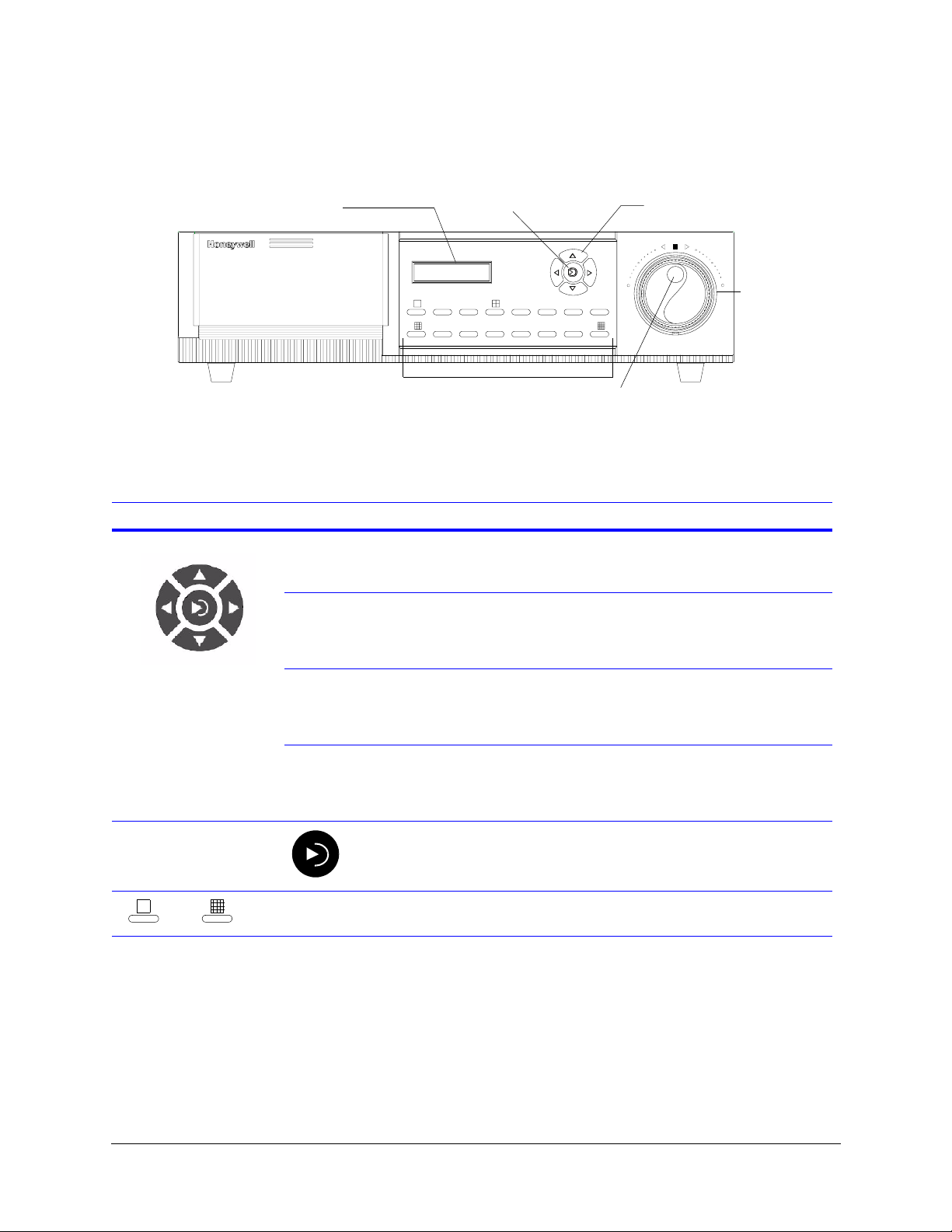
The following figure shows the location of the front panel control buttons. Table 2-1
describes the function of those buttons that you use to configure your system.
Two-line LCD display Enter button
REC PLAY
FUNCTION
Control buttons
REC
6
14
MENU
PLAY
FUNCTION
78
16
15
Inner jog wheel
HRDV16
1 234 5
1291011 13
Camera buttons
(finger controlled)
Table 2-1 Front Panel Menu Navigation Controls
Control button Function
▲ (MENU) • Activate the first level menus
• Move up to the next menu item
• Increment to a larger value.
▼ (FUNCTION) • Move down through the menu structure
• Decrement to a smaller value
• Activates secondary functions when combined with other
control buttons.
(PLAY) • Move right through the menu structure
• If cursor is currently at a menu selection, cycles the value
backward
• Open the Go To search function.
Outer jog wheel
(hand controlled)
(RECORD) • Move left through the menu structure
• If cursor is currently at a menu selection, cycles the value
forward
• Toggles recording on and off.
• Select a function for menu change
Enter/
Select
1
to
16
Camera 1 to
Camera 16
• Confirm a change or selection
• Return to search function if viewing a recorded clip.
Select camera buttons. Some buttons have additional uses
when combined with the FUNCTION control button.
Rev 1.00 6 Document 900.0261
04/05
Page 25
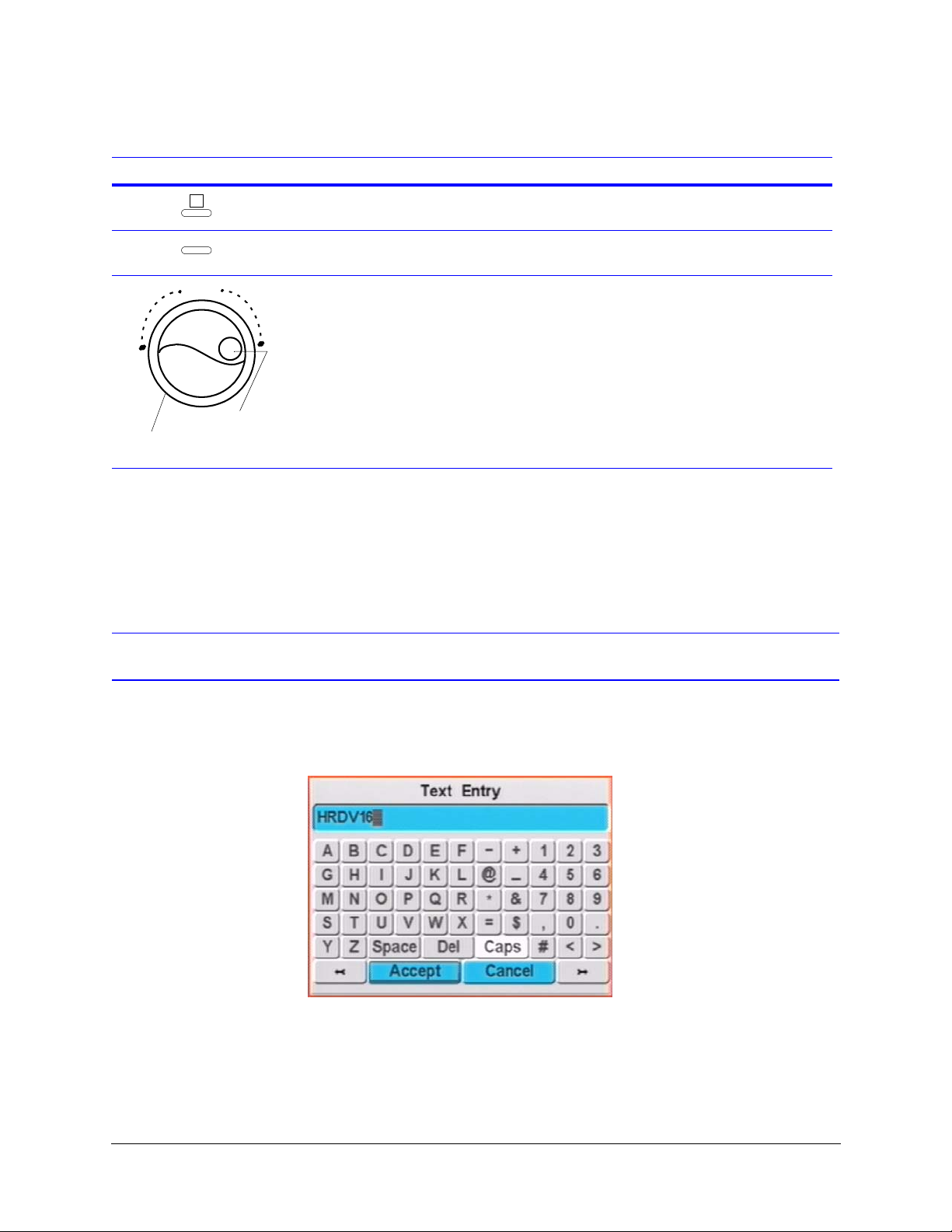
Table 2-1 Front Panel Menu Navigation Controls (Cont’d)
Control button Function
HRDV Reference Guide
1
2
❘ ❘
Inner jog wheel
(finger controlled)
Outer jog wheel
(hand controlled)
Camera 1 • Select camera 1
• Mark a clip for archiving
Camera 2 • Select camera 2
• Select all clips for archiving
Jog wheel • Enter values during Program mode.
• Select clips
• Set clip playback speed. Clip speed options are:
• Forward or reverse at slow motion speed
• Forward or reverse at real-time speed
• Forward or reverse at maximum speed
• Forward or reverse at turbo speed
• Control direction of clip
• Advance or reverse through a previously recorded clip
one frame at a time.
The front panel control buttons have different functions in Operating mode (daily
operation). See Table 15-1. For further information, see Chapter 15, Daily Operation
Overview.
Text Entry Screen
Some Program screens have boxes where you can change the text (for example, the title
of a new report, or the camera title). To change the text in these boxes, highlight the box,
then press Enter. A Text Entry screen displays.
The text you are changing is shown at the top of the Text Entry screen. The individual letter
you are currently changing is highlighted. To move between letters, use the arrow buttons
at the bottom of the Text Entry screen. Use the control buttons on the front panel to move
to the different buttons on the Text Entry screen. To use a button, move to it, then press
Enter on the front panel.
Rev 1.00 7 Document 900.0261
04/05
Page 26
Controls, LCD Display, and Indicators
LCD Display
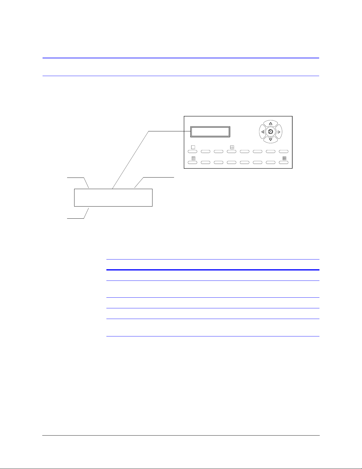
The HRDV front panel has a two-line LCD display that indicates:
• Time and date
• Operation status
Time
Date
10:06:02
10/01/01
MENU
REC PLAY
FUNCTION
RECORD
HRDV16
12345678
9 10111213141516
Options are:
RECORD
PLAY
IDLE
RECPLY
*
LCD display options Description
Upper line
RECORD Displays while in Record mode, even when motion
detect is enabled and no motion is occurring.
PLAY Indicates HRDV is set to Playback mode only.
IDLE Indicates Record is disabled or turned off.
RECPLY Indicates HRDV continues to record while in
Playback mode.
Rev 1.00 8 Document 900.0261
04/05
Page 27
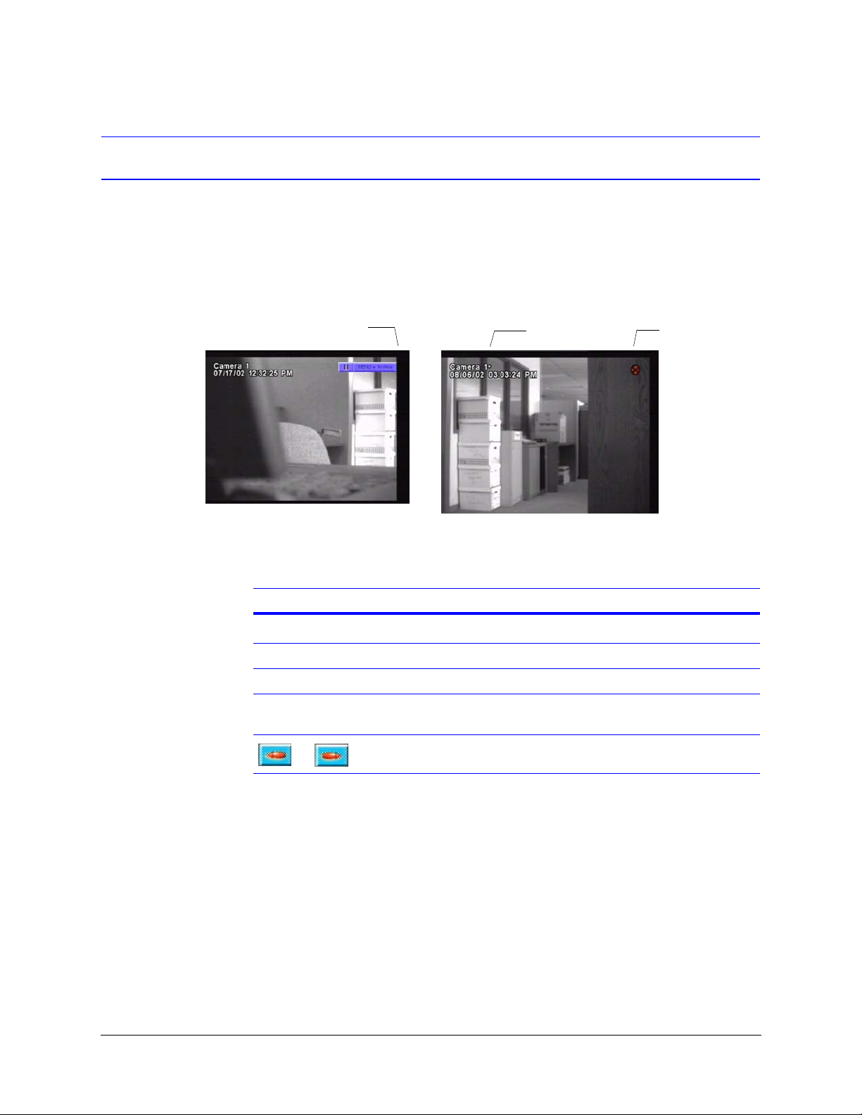
Video Monitor Indicators
The indicators that appear on the video monitor change, depending on which function (that
is, search, play, record) you are currently using, as well as your current configuration
settings. Figure 2-1 shows the location of the control button and record indicators on the
video monitor. Table 2-2 describes the control button functions and Table 2-3 describes the
record indicators.
Figure 2-1 Video Monitor Indicators
Play control button
* indicates a
PTZ camera
HRDV Reference Guide
Record indicator
Table 2-2 Video Monitor Control Buttons
Control buttons Description
❘ ❘
, Clip playing forward or reverse in real-time speed.
❘ , ❘ Clip playing forward or reverse with adjustable speed by user.
, Clip playing forward or reverse with maximum speed or at end
Clip paused by user or clip has ended.
or beginning of clip.
Clip playing forward or reverse at turbo speed.
Rev 1.00 9 Document 900.0261
04/05
Page 28

Controls, LCD Display, and Indicators
Table 2-3 Video Monitor Record Indicators
Record indicator When configuration is set to … The record indicator means …
Dull red Timelapse enabled in Timelapse Recording
screen
Dull red
with slash
Flashing bright
to dull red
Dull red
with X
Simple Timelapse and motion is enabled in
the Timelapse Recording screen
Event recording for any combination of
motion, text or alarm events
Any mode Recording is disabled by operator.
HRDV is currently recording timelapse
video.
No motion is currently detected and the
HRDV is not recording timelapse clips to
the timelapse disk drive partition. HRDV is
waiting for a motion event.
Motion, text, or alarm event currently
detected and active.
Rev 1.00 10 Document 900.0261
04/05
Page 29

System Startup
This chapter covers:
• An overview of the components in an HRDV system
• How to turn on the HRDV for the first time and perform an initial system check
• A general procedure for system startup
• How to connect the HRDV to all peripheral equipment
System Components
The HRDV is designed to work with a variety of other equipment. The HRDV16 supports
16 video channel inputs and the HRDV8 supports 8 video channel inputs. You decide
which equipment to connect to the HRDV16/8 to meet your individual needs. This can be
any combination of:
3
Video Cameras
• There are 16 analog video inputs and 16 analog video outputs. (The HRDV8 has 8
analog video inputs and 8 analog video outputs.)
• Video signal format is standard NTSC/PAL color or EIA/CCIR monochrome.
• Video inputs are composite BNC with BNC loop connectors.
• Video outputs are composite BNC or S-Video connectors.
Video Monitor
• There are three monitor outputs.
• The primary video monitor can be connected to Monitor 1 out— a composite BNC
connector—or to the S-Video output. The S-Video output has the same output as
Monitor 1 but in S-Video format.
• Monitor 2 out uses a composite BNC connector.
Rev 1.00 11 Document 900.0261
04/05
Page 30

System Startup
Audio
• There is a single digital channel of audio, both in and out. The audio out connects to
an amplifier.
• Both audio in and audio out use a standard RCA connector.
Text Insertion Ports
• There are four Text Insertion ports suitable for any Asynchronous ATM/POS Interface
(ATMs, cash registers, a door card reader access system).
• A single DB25 male connector supports RS485 and RS232.
• Inputs can be set to display up to 40 characters per line and up to 10 lines per camera
on your output. After text has been recorded with the video image, you can use the
search function to search for specific text.
PC Remote Access Port
The PCMCIA remote access port can be used for a PCMCIA modem or Ethernet card.
This port is used, together with the HRDV16/8 Remote Access Software, to control your
HRDV unit from a PC. Remote connection allows you to collect data for analysis or to
access the HRDV16/8 video monitoring, video playback, alarm reset, and Program mode
from a remote site. All remote access to the HRDV16/8 is protected by password security.
Hard Drives
• The HRDV16/8 supports up to four internal IDE or SCSI hard drives, one of which can
be removable.
• The HRDV16/8 supports one removable hard drive or compatible SCSI drive with
removable media in the front loading drive.
• Connect a 68-pin SCSI-2 connector for up to three external SCSI drive or SCSI RAID
device.
Alarm Input/Output
The HRDV16 has 16 alarm inputs and four alarm outputs. The HRDV8 has 8 alarm inputs
and four alarm outputs.
Rev 1.00 12 Document 900.0261
04/05
Page 31

Performing an Initial System Check
Turning On the HRDV the First Time
1. Unpack the HRDV and place it on a flat surface.
2. Attach the AC power cord to the HRDV rear panel (see Figure 3-1) and plug the other
end into an 110 VAC receptacle.
3. Observe the LCD display on the HRDV front panel. The message Power up displays
alternately between the top and bottom of the LCD screen for approximately 60
seconds.
4. The time and date displays indicating the HRDV is ready for operation. You can now
attach a monitor.
HRDV Reference Guide
Rebooting (Restarting) the HRDV
There is no on/off switch on the HRDV. To restart it:
1. Disconnect the power cable from either the HRDV or from the wall socket.
2. Wait 15 seconds, then re-connect the power cable to apply power to the HRDV.
This wait allows any stored capacitance to discharge clearing memory for proper
operation.
Attaching a Monitor
1. Plug your monitor into an AC receptacle.
2. Connect a BNC cable to the Video In jack on the monitor. Connect the other end of
the BNC cable to the Mon 1 jack on the HRDV rear panel (see Figure 3-1).
3. Turn on your monitor, then press the MENU button on the HRDV. The monitor
displays a Select a user login screen.
You are now ready to set the HRDV to factory defaults.
Setting the HRDV to Factory Defaults
1. Log in to the HRDV (see Entering Program Mode, page 19).
2. From the Main Menu screen, select System Setup.
3. Select Default Settings.
Rev 1.00 13 Document 900.0261
04/05
Page 32

System Startup
4. The message Warning! This will delete your existing configuration
You are now ready to attach camera(s) to the HRDV.
Attaching a Camera
1. Unpack a compatible camera and place it on a flat surface.
2. Connect power as required to the camera (refer to the documentation that came with
3. Connect one end of a BNC cable to the Video jack on the camera. Connect the other
This completes the initial system check. You are now ready to install your HRDV system.
(except for the disk settings)! PROCEED? appears. Select OK.
the camera).
end of the BNC cable to the In 1 jack on the HRDV rear panel (see Figure 3-1).
The monitor displays what the camera is viewing. This indicates a successful
connection.
Initial Installation Mandatory Steps
To ensure maximum system performance,
make sure that you complete each step in
the proper sequence.
The initial HRDV16/8 system installation consists of the following steps:
1. Power up the HRDV16/8 unit and wait two minutes.
2. Log in to the HRDV (see Entering Program Mode, page 19).
3. Set the system to the factory defaults:
a. Press MENU on the HRDV16/8 front panel. Select Menu at the initial menu
screen.
b. Select System Setup and then select Default Settings. Wait ten seconds.
c. The message Warning! This will delete your existing
configuration (except for the disk settings)! PROCEED? appears.
Select OK.
4. Format the hard drive:
a. Navigate to the Disk Setup screen (MENU
and select Format all.
➤ Storage Setup ➤ Disk Setup)
Rev 1.00 14 Document 900.0261
04/05
Page 33

HRDV Reference Guide
Note Formatting the hard drive will result in permanent loss of all images
and other information (for example, text and audio) recorded on the
hard drive.
In the event of an accidental Format All, go to the Data Recovery
screen to have the system attempt to restore the file system to its
original state (see Data Recovery, page 53).
b. The message Attention! Any future changes to disk partitioning
will require a FORMAT ALL and your recorded data will be
lost. Select OK.
c. The message Warning! This will delete all of the data on your
drives! PROCEED? Select OK.
5. Connect the HRDV16/8 to all the local peripherals, including cameras, monitors,
alarm inputs and outputs, external storage, and ATM/POS interface equipment (see
Connecting the HRDV16/8 to Peripherals).
6. (Optional) Connect the HRDV16/8 to a PC via a modem, null modem, or Ethernet for
remote operation. For more information, refer to the HRDV RAS User Guide.
7. Configure the HRDV16/8 for desired operation. See Chapter 4 to Chapter 14 for
detailed information, or see Chapter 5, Easy Configurator for an overview of the quick
setup procedure.
8. Format the hard drive again (see step 4 above).
9. To start recording, press REC on the HRDV16/8 front panel, then enter a user name
and password when prompted.
Connecting the HRDV16/8 to Peripherals
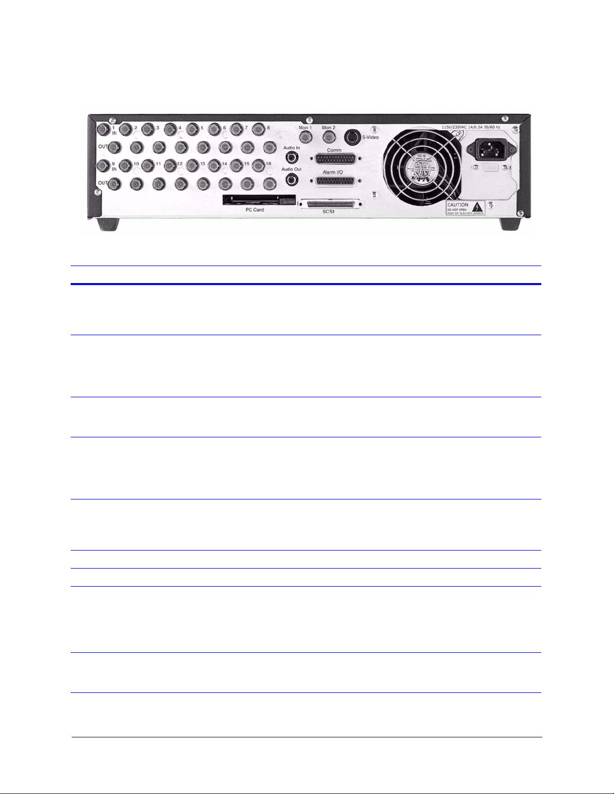
Figure 3-1 shows the rear panel connections on the HRDV16. Follow the instructions in
Table 3-1 to connect the HRDV16 to all peripherals.
Note The HRDV8 rear panel looks the same as the HRDV16 except that it has 8
analog video inputs, 8 analog video outputs, and 8 alarm inputs.
Rev 1.00 15 Document 900.0261
04/05
Page 34
System Startup
Figure 3-1 Rear Panel Connections (HRDV16 Shown)
Table 3-1 Rear Panel Connections
Label Connection description
In 1 to 16 Connect the composite analog video inputs—1 to 16—to the BNC connectors on the rear
panel. Voltage levels should be 1 VDC ± 0.2 VDC.
Note The HRDV8 has 8 analog video inputs.
Out 1 to 16 If looping is required to go to a second destination (for example, a matrix switch) connect the
composite analog video inputs from input cameras (up to 16) to the corresponding composite
analog video output BNC connectors. Termination is selected in the Program setup menus.
Note The HRDV8 has 8 analog video outputs.
Mon 1 Connect the primary CCTV monitor to the digitally processed, Mon 1 (main monitor) output.
This output is a composite analog output with full or multiscreen views, displays configuration
menus, and a variety of text overlays during operation.
Mon 2 Connect an optional CCTV monitor to the Mon 2 (spot monitor) output. This output always
provides full screen sequential switching views of some or all cameras. This display is
completely independent of the Monitor 1 display.
Note This output does NOT display configuration menus.
S-Video Connect the primary monitor to the digitally processed, S-Video output. This output is an
S-Video output with full or multiscreen views, and displays the user interface during Menu
mode, and a variety of text overlays during operation. It has the same output as Monitor 1, but
in S-Video format.
Audio In Connect the line level source to the audio input RCA connector.
Audio Out Connect the RCA audio output of the HRDV16/8 to the RCA audio input of the CCTV monitor.
Comm Connect the serial interfaces for ATMs 1 to 4 to the four ATM RS232 ports.
Connect the remote control or external modem to the control RS232 port with handshaking.
Connect the controlled device to the telemetry, four-wire RS485 port.
See Appendix H for connector pinouts.
Alarm I/O Connect external alarm devices to the HRDV16/8 alarm inputs. The HRDV16 has 16 alarm
inputs and the HRDV8 has 8 alarm inputs. Connect the HRDV16/8 alarm outputs to trigger
external devices. See Appendix H for connector pinouts.
Rev 1.00 16 Document 900.0261
04/05
Page 35

HRDV Reference Guide
Table 3-1 Rear Panel Connections (Cont’d)
Label Connection description
PC Card Insert approved PCMCIA card for network or modem connectivity. Card validation occurs after
powerup, and can be verified on the System Information screen (see Viewing System
Information on page 183). You must enable remote access for the system to recognize and
read the PCMCIA card.
Note A list of supported devices is posted on the Honeywell Video Systems web site.
SCSI Connect an external RAID device to this SCSI connector:
1. Connect an external SCSI device to the 68-pin SCSI control port on the rear panel. Set the
SCSI ID in the range of 4 to 6. The SCSI ID must not conflict with the ID of internal SCSI
devices.
2. Apply power to the external device prior to turning the HRDV on. This HRDV queries the
device during start up to ensure it is functioning properly.
Note A list of supported devices is posted on the Honeywell Video Systems web site.
Power The power for the HRDV16/8 unit is 110 VAC/60 Hz (NTSC) and 220 VAC/50 Hz (PAL).
See Appendix D for typical network installations.
Rev 1.00 17 Document 900.0261
04/05
Page 36

System Startup
Rev 1.00 18 Document 900.0261
04/05
Page 37

Programming Overview
After your HRDV16/8 is connected to all the peripheral equipment, you need to program
your system. You enter all system settings in Program mode. Program mode also gives
you access to video reports and alarm reports.
This chapter describes:
• Entering and exiting Program mode
• The menu structure
For daily system operations, see Chapter 15.
Entering Program Mode
4
Note Recording stops in program mode.
To enter Program mode:
1. Press MENU on the HRDV16/8 front panel.
2. You are prompted to enter your user name and password. Press one of the Camera
buttons to select a user name (for example, Camera 1 is User 1). The factory default
is User 1.
3. Use the Camera buttons in sequence to enter a password for that user name. The
default password is 1234. As you enter each number in your password, you see the
outlined square move across the screen.
4. Press Enter to accept the changes.
Note If you do not want to enter Program mode at this time, move to the Cancel
button, then press Enter.
Rev 1.00 19 Document 900.0261
04/05
Page 38
Programming Overview
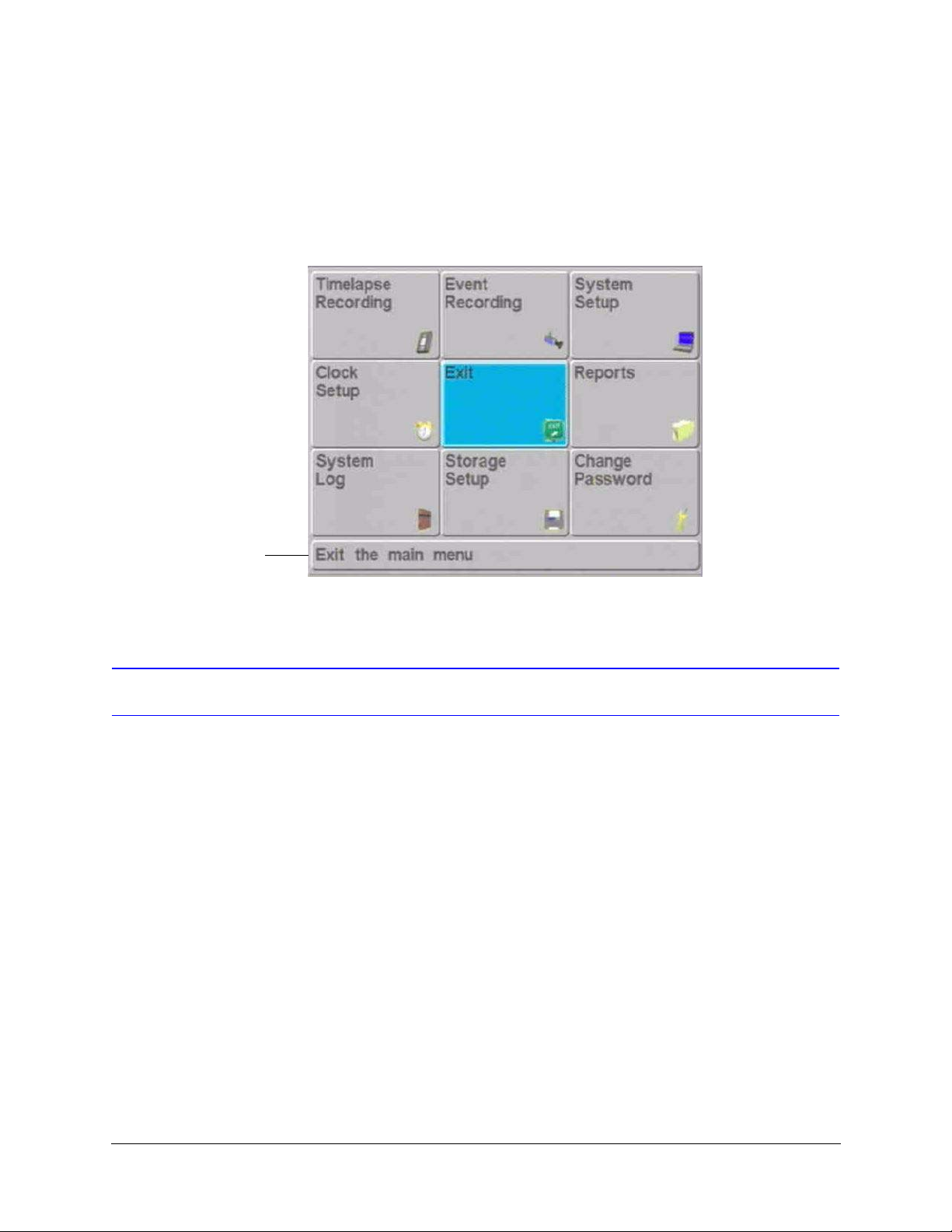
After entering the correct password, select Menu to enter the Main Menu (see Figure 4-1).
Or you can select Easy Configurator and go to Chapter 5, Easy Configurator to perform a
quick setup. Use the control buttons to move around the screen. Highlight a menu option,
then press Enter to select it. As you highlight each menu option, the dialog box at the
bottom describes the current selection.
Figure 4-1 Main Menu
Describes currently selected
menu option
Navigating in the Menus
While you are using Program mode you can control the cursor on the screen with the
control buttons on the front panel. The control buttons may be used to move to different
parts of the screen, to scroll through a list, or to add text to a report. The part of the screen
that is active—and will be affected by the control buttons—will always be outlined by a
selection box. See Table 2-1 for more information on the front panel control buttons.
Some Program screens have boxes where you can change the text (for example, the title
of a new report, or the camera title). When you want to change the text on screen, use the
cursor controls to highlight the text and press Enter to open the Text Editor.
For all settings, press Enter to accept the change and to leave the setting mode so that you
can move to another area of the screen.
Method One: Cursor Controls
1. Highlight the box or line you wish to edit. Press Enter. If the field requires the user to
input text, the Text Entry Screen will open.
Rev 1.00 20 Document 900.0261
04/05
Page 39
HRDV Reference Guide
2. If the field requires no text input, use the cursor controls to edit the options.
Press to change
options
Enter button
Press to
move left
Press to change
options
OR use inner jog wheel.
Press to
move right
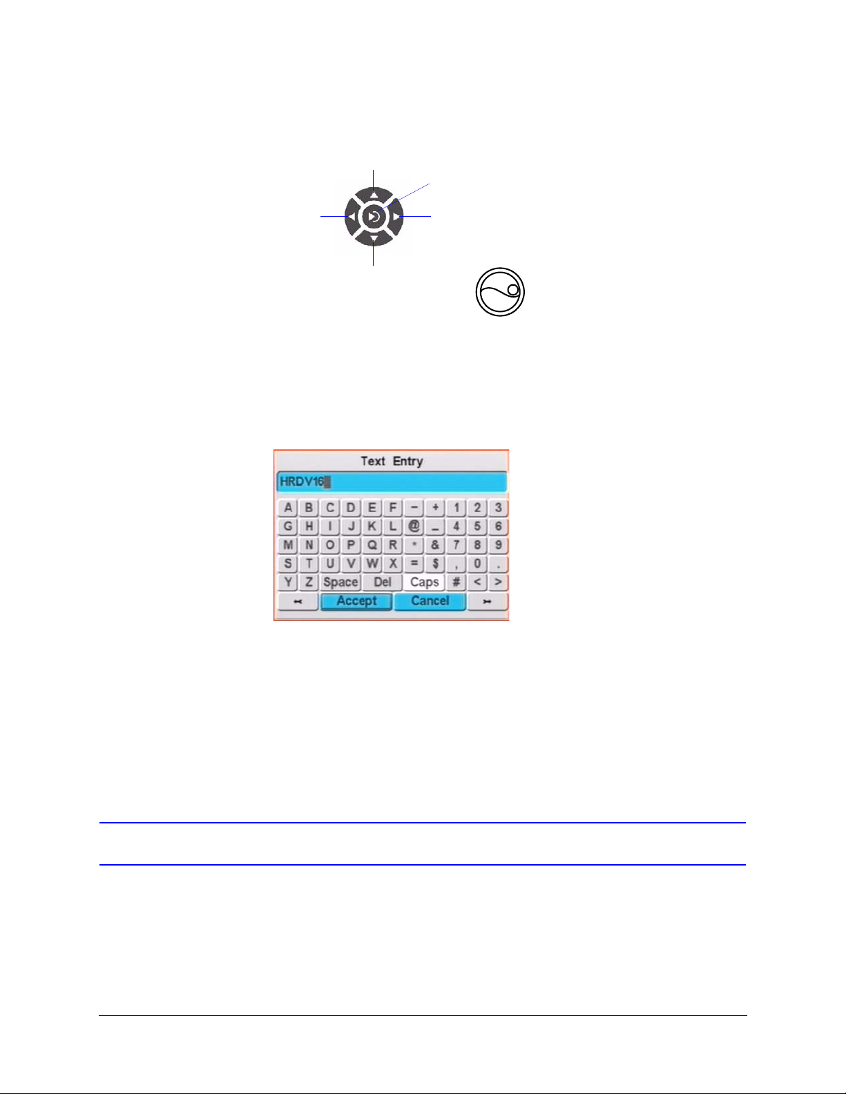
Method Two: Text Editor
1. Highlight the box or line you wish to edit.
2. Press Enter to open the Text Entry screen.
Figure 4-2 Text Entry Screen
3. The text you are changing is shown at the top of the Text Entry screen. The individual
letter you are currently changing is highlighted. To move between letters, use the
arrow buttons at the bottom of the Text Entry screen. Use the control buttons on the
front panel to move to the different buttons on the Text Entry screen. To use a button,
move to it, then press Enter on the front panel.
4. When you are satisfied with your changes, move to the Accept button, and press
Enter. The text will display in the box or line on the screen you are editing.
Activating Configuration Changes
Whenever you make changes to an editable screen, you must press Enter to confirm the
change. When you have completed all desired changes to a screen, press Accept to
activate your configuration choices. Press Cancel to return all changes made prior to
pressing Accept to their previous settings.
Rev 1.00 21 Document 900.0261
04/05
Page 40

Programming Overview
Exiting Program Mode
To exit Program mode, highlight Exit on the Main Menu (see Figure 4-1), then press Enter.
The HRDV automatically exits Program mode and starts recording again after five minutes
of inactivity.
Menu Structure
Figure 4-3 shows the menu structure of the HRDV16/8.
Figure 4-3 HRDV16/8 Menu Tree
Main Menu
Timelapse Recording Event Recording Clock SetupReportsSystem Setup
Day Schedule
Holiday Setup
Advanced Setup
Normal Setup
Alternate Setup
Motion Events
Zone Setup
Text Events
Text Trigger
Strings
Alarm Events
General Setup
Pre-Event Setup
Calendars
Motion
Text
Alarm
Text Ports
Text Parsing
Video Inputs
Display Setup
Main Monitor
Spot Monitor
Covert Setup
User Preferences
System Utilities
Add Disk
Download Software
Data Recovery
Filesystem Verify
Holdup Setup
Default Settings
System Info
Remote Access
Advanced Remote Setup
Text Protocol
Setup
Setup Email
Create
Edit
Delete
Run
Run Auto
Login
User
Permissions
Storage SetupChange Password
Disk Setup
Disks
System Log
S.M.A.R.T.
Rev 1.00 22 Document 900.0261
04/05
Page 41
Easy Configurator
Situation
HRDV recorders with firmware version 2.30 and later include the Easy Configurator
feature. The Easy Configurator will set up the HRDV system in ten minutes or less with the
option of fine tuning the system afterwards using the individual menu screens in the Main
menu.
Setting Up with Easy Configurator
5
Before starting to use the Easy Configurator, you must install all the components in your
system (see Chapter 3, System Startup for information on installation). To start the Easy
Configurator:
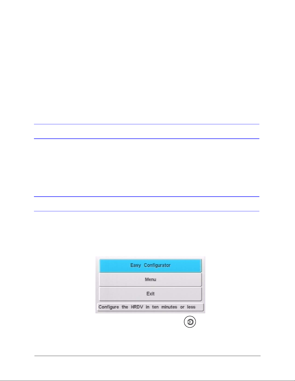
1. Press the MENU button on the HRDV front panel.
Figure 5-1 Initial Easy Configurator Screen
2. Select Easy Configurator and press Enter .
Rev 1.00 23 Document 900.0261
04/05
Page 42
Easy Configurator
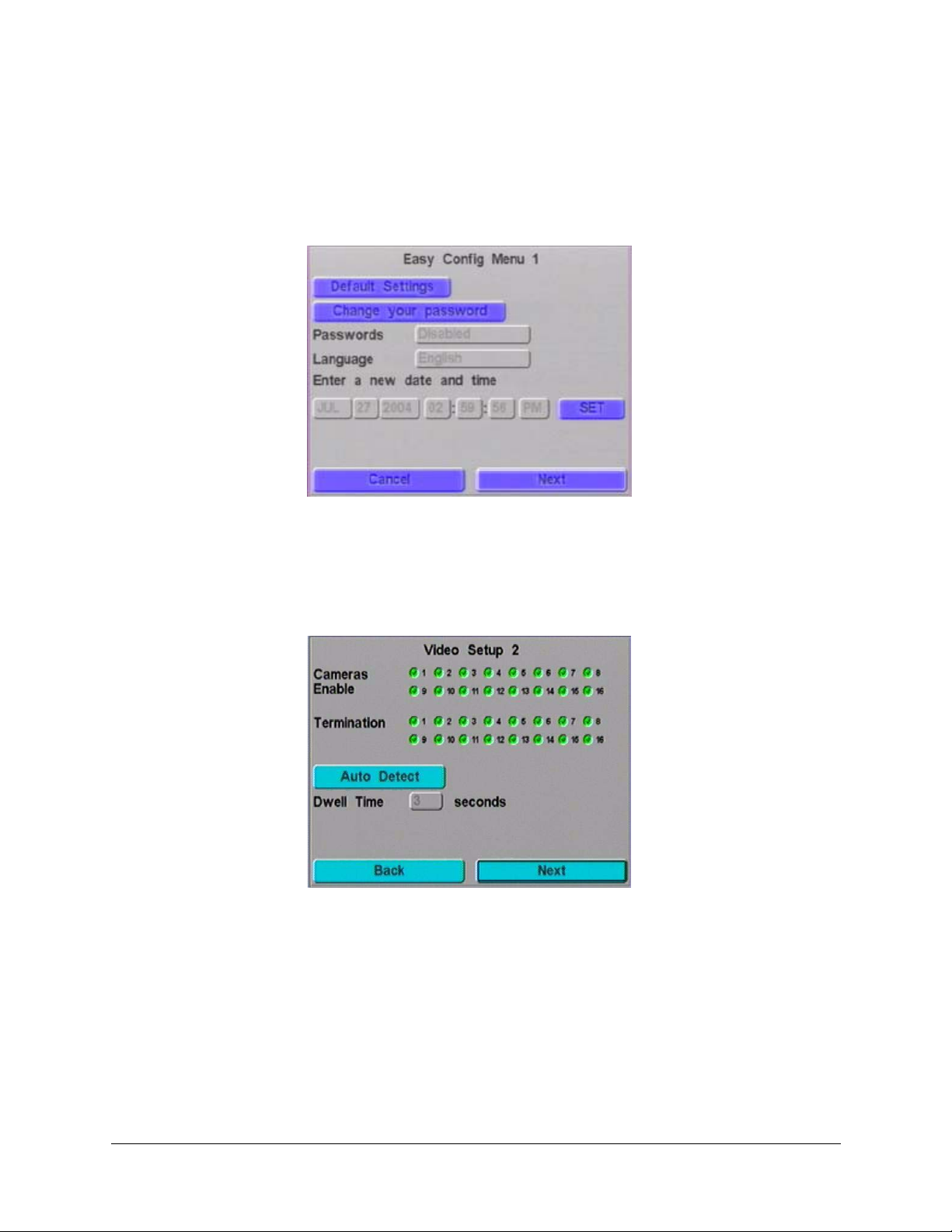
3. The Easy Config Menu 1 screen opens (see Figure 5-2). In this screen you may set
the settings to be defaulted, change the date, time and language and enable, disable
or change your passwords (see Changing the Clock Settings, page 33 and Changing
Passwords, page 29 for more information). Select Next to continue.
Figure 5-2 Easy Config Menu Screen
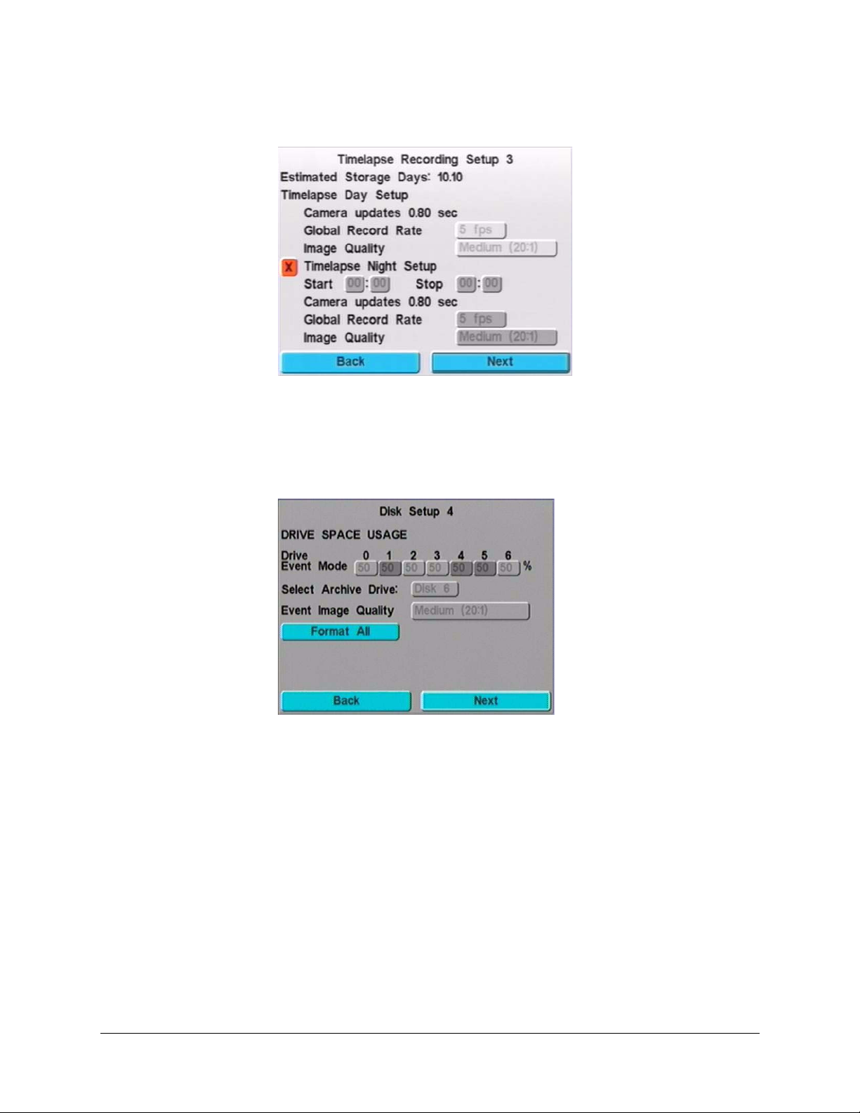
4. The Video Setup 2 screen opens (see Figure 5-3). In this screen you may set up your
video inputs. Auto Detect will detect whether video is present or you may enable and
set the camera terminations manually. Dwell time for sequencing may also be set
here from 1 to 30 seconds (see Display Setup, page 94 and Configuring the Video
Inputs, page 98 for more information). Select Next to continue.
Figure 5-3 Video Setup Screen
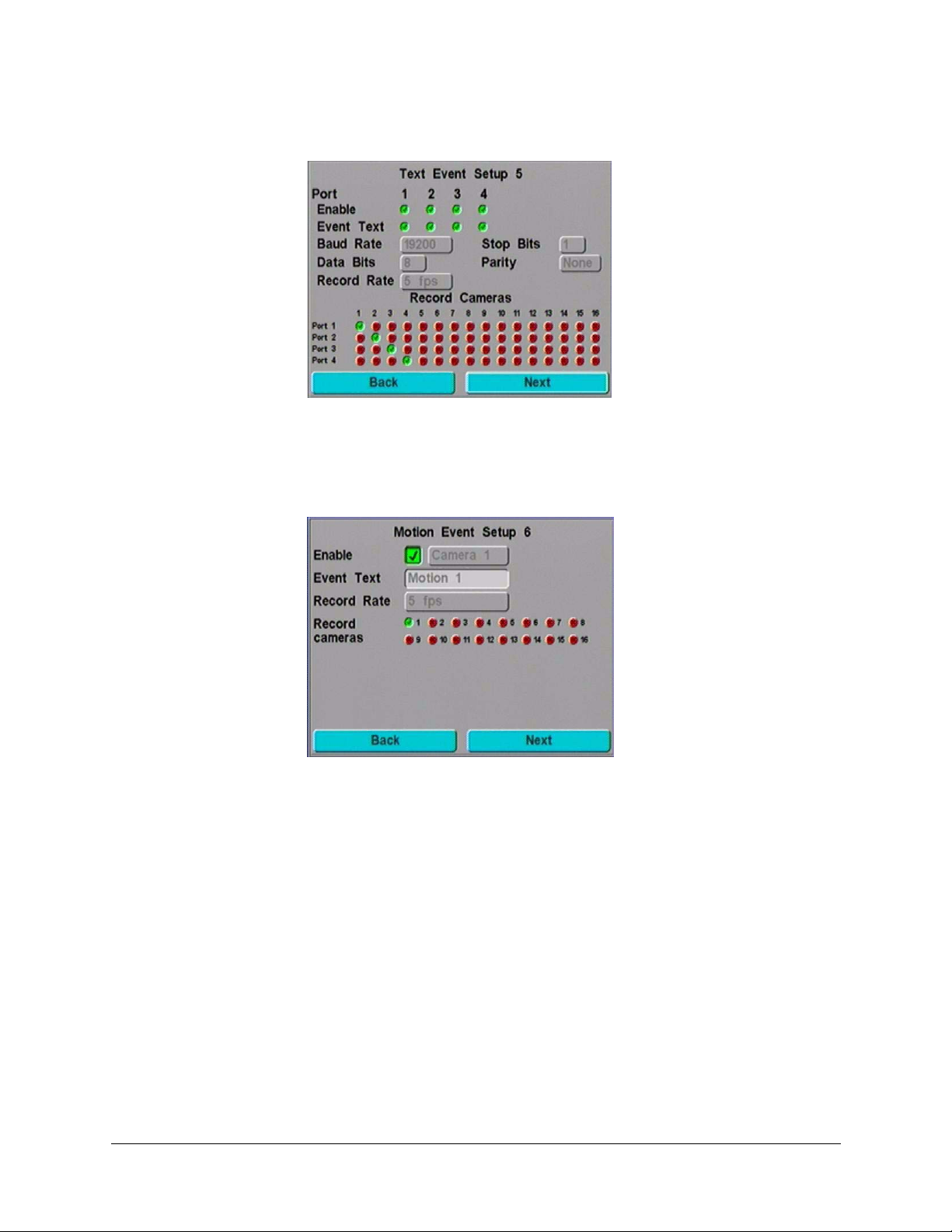
5. The Timelapse Recording Setup 3 screen opens (see Figure 5-4). In this screen you
may set up your Global Record Rate and Image Quality for normal and alternate
timelapse recording times (see Setting Up Simple Timelapse, page 62 for more
information). Select Next to continue.
Rev 1.00 24 Document 900.0261
04/05
Page 43
HRDV Reference Guide
Figure 5-4 Timelapse Recording Setup Screen
6. The Disk Setup 4 screen opens (see Figure 5-5). In this screen you may set up your
disk drives. Formatting all the drives, partitioning between timelapse and event
recording, selecting the Archive Drive and setting the Event Image Quality may all
be accomplished here (see Configuring Storage Setup, page 47 for more information).
Select Next to continue.
Figure 5-5 Disk Setup Screen
7. The Text Event Setup 5 screen opens (see Figure 5-6). In this screen you may set up
your Text Event recording. Setting up the Ports, selection of cameras and Record
Rate may all be accomplished here (see Step 1. Set Up Text Ports, page 143 and Step
3. Set Text Events, page 146 for more information). Select Next to continue.
Rev 1.00 25 Document 900.0261
04/05
Page 44
Easy Configurator
Figure 5-6 Text Event Setup Screen
8. The Motion Event Setup 6 screen opens (see Figure 5-7). In this screen you may set
up your Motion Event Recording, such as Video Inputs selected to trigger motion, the
Record Rate and selected cameras to record (see Setting Motion Events, page 77 for
more information). Select Next to continue.
Figure 5-7 Motion Event Setup Screen
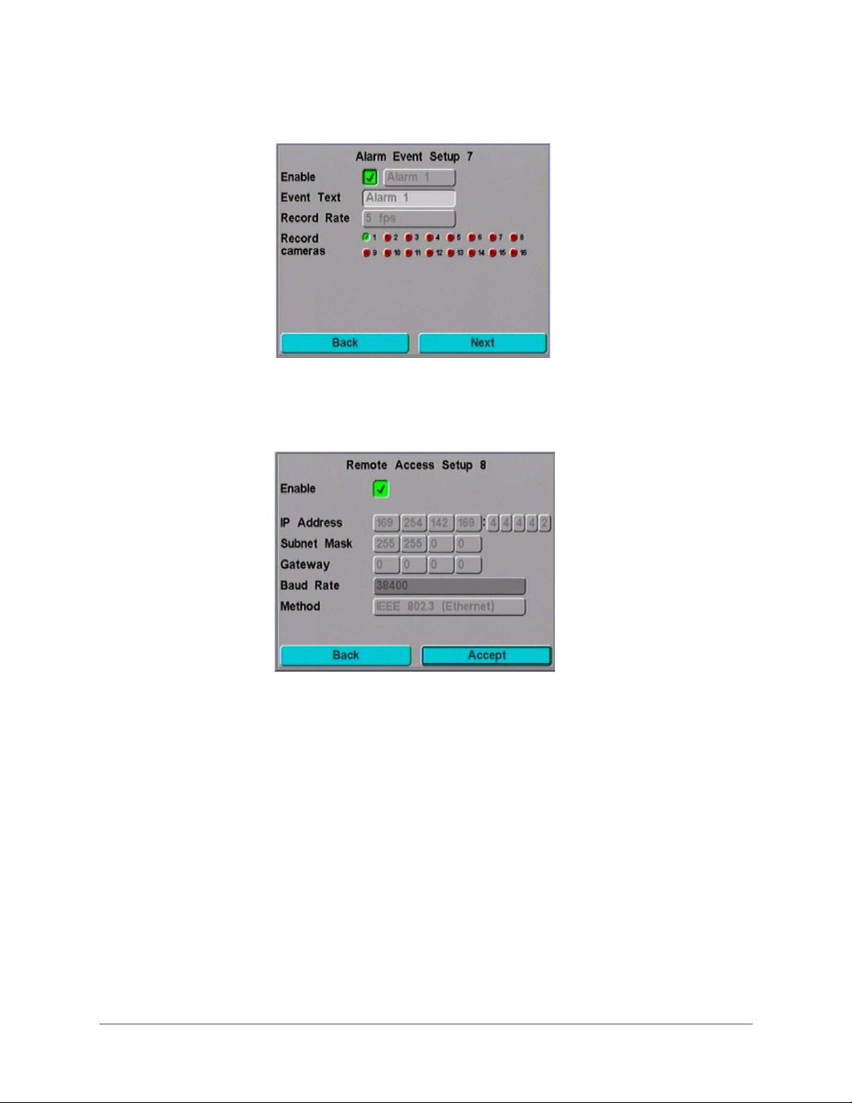
9. The Alarm Event Setup 7 screen opens (see Figure 5-8). In this screen you may set up
your Alarm Event Recording by enabling Alarm Inputs, setting the Record Rate and
selecting cameras to record (see Setting Alarm Events, page 37 for more information).
Select Next to continue.
Rev 1.00 26 Document 900.0261
04/05
Page 45
HRDV Reference Guide
Figure 5-8 Alarm Event Setup Screen
10. The Remote Access Setup 8 screen opens (see Figure 5-9). In this screen you may
set up Remote Access, IP Address, Gateway and other parameters (see Enabling
Remote Access, page 135 for more information). Select Accept to finish.
Figure 5-9 Remote Access Setup Screen
11. Your HRDV is now ready to use. If you want to set up some of the advanced features
not included here (for example, Holiday Timelapse Recording) press the MENU
button on the front panel and enter the Main menu.
Rev 1.00 27 Document 900.0261
04/05
Page 46

Easy Configurator
Rev 1.00 28 Document 900.0261
04/05
Page 47

User Access
You can configure up to 16 system users (8 for the HRDV8) with their own password and
user access levels. Two password levels are defined:
User User level access is limited to the operational aspects of the
Administrative Administrative level allows access to all system operation and
6
system:
• Camera selection for display, both individual and grouping
(Camera buttons)
• Go To search and Playback (PLAY button)
• Searches (FUNCTION + PLAY buttons)
• Reports (FUNCTION + MENU buttons)
configuration levels. At least one user must have administrative
access enabled.
The factory defaults are set at User 1, password 1234, with
administrative access.
This chapter describes how to:
• Change passwords
• Change user names
• Set permission levels
• Reset passwords
• Recover the Administrator password
Changing Passwords
Before you set up your HRDV16/8 system, we recommend that you change the default
passwords and establish your initial user identification and permission levels.
Note You must have administrative access to change user
passwords and access.
Rev 1.00 29 Document 900.0261
04/05
Page 48
User Access
Use the Change Password menu to:
• Change any of the user identifications and passwords
• Configure the permissions supported with each user
You can also enable or disable the password function globally (for all users) from the User
Preferences menu (see User Preferences Screen on page 43).
To change a user password:
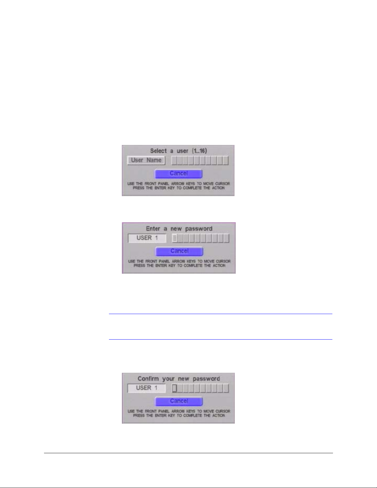
1. On the main MENU, use the Control buttons to move to the Change Password
option, then press Enter. Figure 6-1 displays.
Figure 6-1 Select a User Screen
2. Press one of the Camera buttons for the desired user (for example, Camera 1 selects
User 1). The following dialog box displays.
3. Enter a new numeric password. The password can be any combination of digits 1 to
4, up to 10 keystrokes long. Use the Camera buttons to enter your new numeric
password.
Note If you do not want to change your password at this time, press ▼ to highlight
the Cancel button, then press Enter.
4. Press Enter. The Select a user dialog box re-appears.
5. Re-enter the same user name. The Confirm your new password dialog box displays.
6. Confirm your new password by re-entering the password.
Rev 1.00 30 Document 900.0261
04/05
Page 49
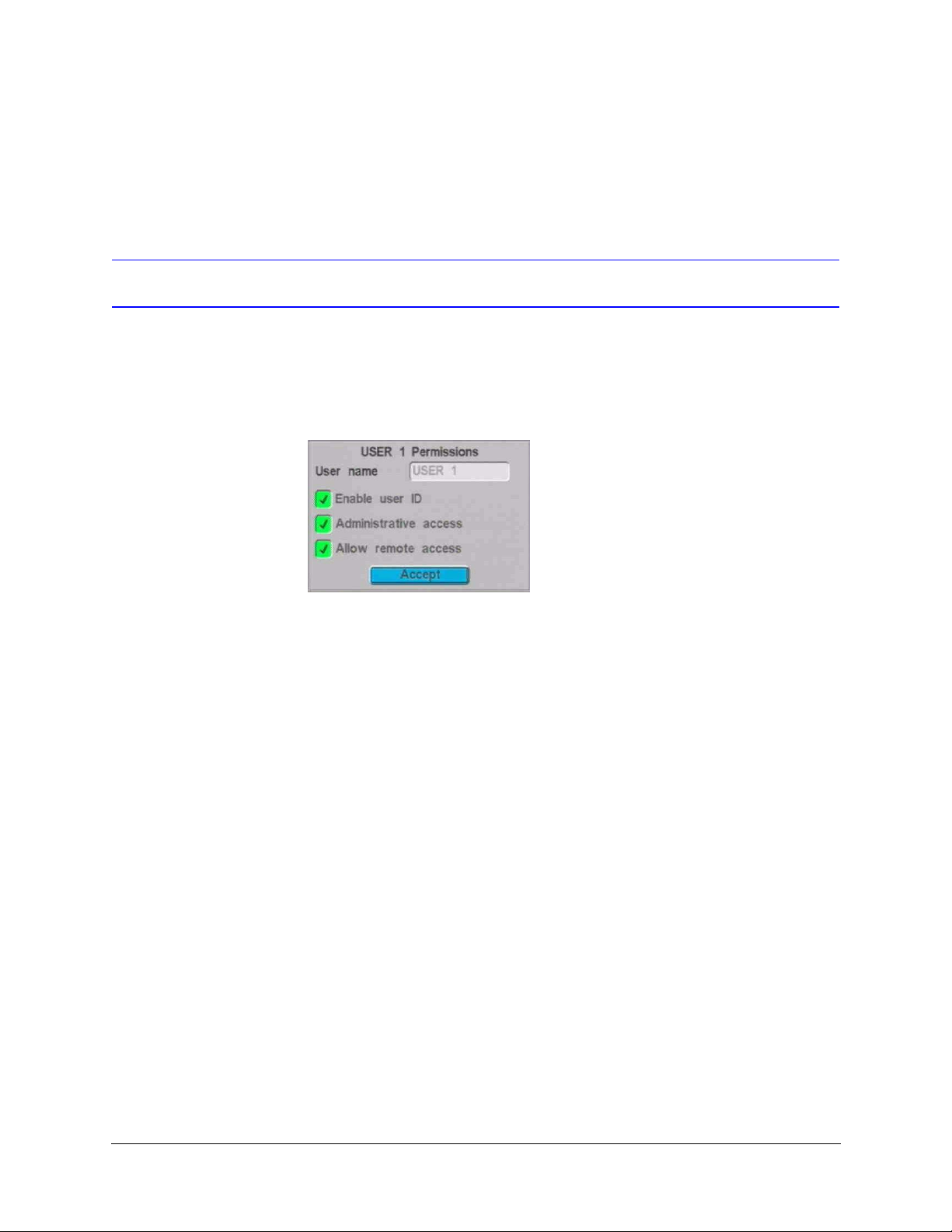
7. The User Permissions screen (see Figure 6-2) for that user name displays, indicating
you have successfully changed the password.
Changing User Names
On the User Permissions screen you can:
• Change the user name
• Enable or disable permission levels
Figure 6-2 User Permissions Screen
HRDV Reference Guide
User names can be one to eight characters long (including the user number). The name
can be a combination of uppercase or lowercase letters, numerals, and symbols. To
change a user name:
1. On the User Permissions screen, press
Enter.
2. The Text Entry dialog box displays (see Figure 4-2). Use the control buttons to change
the user name and press Accept to confirm the changes.
3. To change the user permission levels, proceed to the next section. To accept the
changes as displayed, press Enter to exit this screen.
to move to the User name field, then press
Rev 1.00 31 Document 900.0261
04/05
Page 50

User Access
Setting Permission Levels
You can give each user different access permissions. To change the permission levels:
1. Use the control buttons to navigate to the desired field.
2. Press Enter to enable or disable the field.
Field Description
Enable user ID If this field is disabled, that user has no access to the HRDV16/8. If you disable all
users, then the password function is disabled when you use the unit locally (you
are not prompted for a user name or password).
At least one user name must be enabled if you want to use remote access.
Administrative access If this field is disabled, that user cannot use any of the functions accessed with the
following buttons:
•MENU
• RECORD
At least one user must have administrative access enabled.
Allow remote access If this field is disabled, that user cannot use Remote Access. For more information
on remote access, refer to the HRDV RAS User Guide.
3. Press Enter to accept the changes and exit this screen.
Recovering Administrator Password
In the unlikely event that the Administrator password has been forgotten and you cannot
log on to your HRDV16/8, contact Technical Support for help in recovering the
Administrator password.
Rev 1.00 32 Document 900.0261
04/05
Page 51
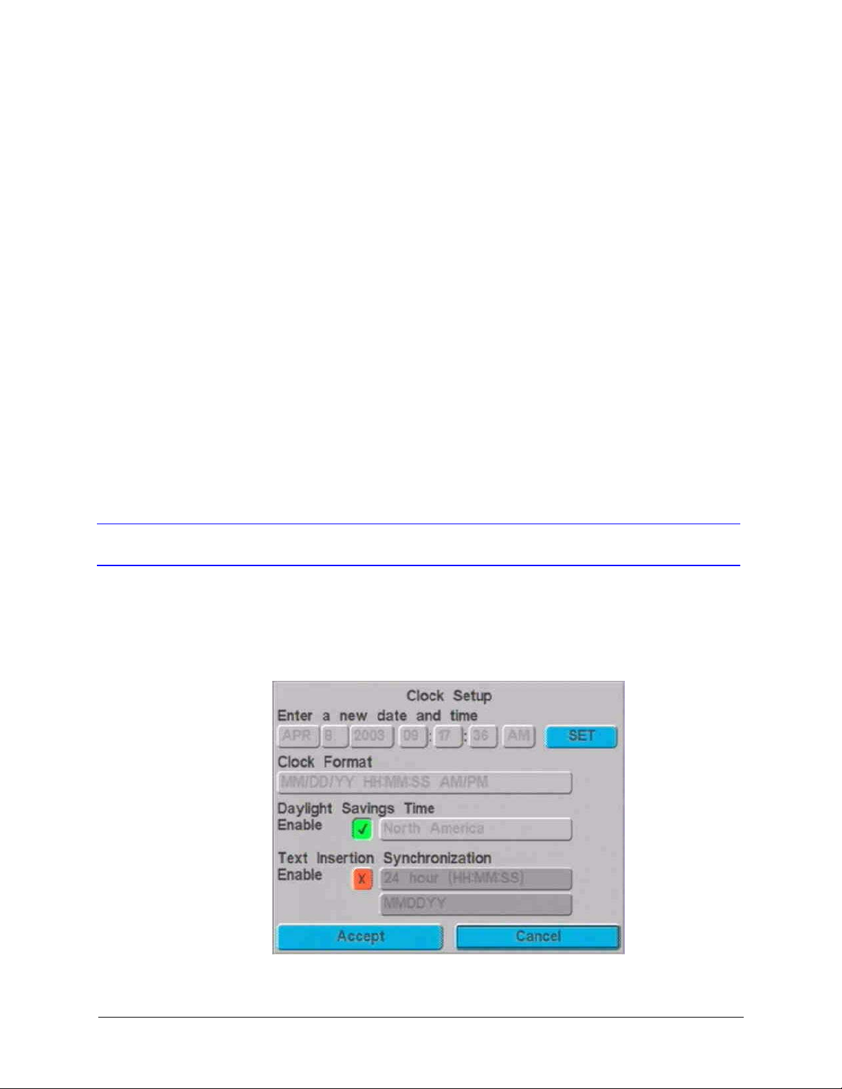
Clock Setup
This chapter tells you how to use the Clock Setup screen to:
• Set the system current date and time
• Enable Daylight Saving time for your geographic area
• Enable text insertion synchronization of the HRDV16/8 to devices connected to your
Text Insertion Input ports (for example, an external ATM or cash register). If more
than one input contains clock information, we recommend that you do not use this
option.
• Set the date and time format to your regional preference
Changing the Clock Settings
7
To change the clock settings:
1. Access the Clock Setup screen as follows: MENU ➤ Clock Setup. Figure 7-1
displays.
Figure 7-1 Clock Setup Screen
2. Use the cursor controls to move through the fields.
Rev 1.00 33 Document 900.0261
04/05
Page 52

Clock Setup
3. Press Enter to select an item; then use the and to change the value. You can
also use the inner jog wheel to change the value.
4. Press Enter to confirm a value.
Field Description
Enter a new date and time Set the system time and date.
Activate a box by pressing Enter, then press or or the jog wheel to change
the value. Press Enter to accept the value.
Clock Format Set the time in 12-hour (AM/PM) or 24-hour format. Use the control buttons or jog
wheel to cycle through the options:
DD/MM/YY HH:MM:SS AM/PM (12-hour clock format)
DD/MM/YY HH:MM:SS (24-hour clock format)
MM/DD/YY HH:MM:SS AM/PM
MM/DD/YY HH:MM:SS
Daylight Saving Time Enable (default) or disable Daylight Saving Time for your geographic location.
Time varies from one region to another. If enabled, the HRDV16/8 automatically
adjusts itself by one hour in the Spring and one hour in the Autumn.
Options are:
North America, Europe, Australia
If a user is operating the HRDV16/8 when the change to Daylight Saving time takes
place, the time change does not take effect.
Text Insertion
Synchronization
Also, if the HRDV16/8 is recording an event at the time of the Daylight Saving time
change, recording temporarily stops, the time changes, and then the recording
begins again.
Enable or disable (default) text insertion synchronization. Must be enabled to
change the date and time fields.
Enable text insertion synchronization ONLY if you want the HRDV16/8 set to the
date and time used by one externally connected device.
5. When you have finished entering the correct date and time, press SET to reset the
HRDV16/8 clock.
6. Move to the Accept button and press Enter to save changes and exit to the Main
Menu.
Rev 1.00 34 Document 900.0261
04/05
Page 53
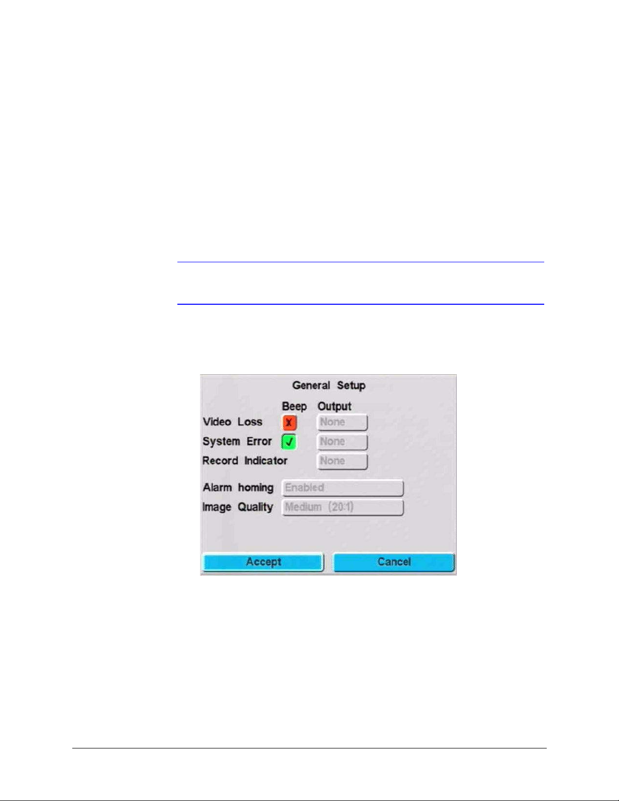
Alarm Setup
This chapter tells you how to set alarm events and configure alarm features.
Note You must allocate some disk space to event recording for this to work. For
Access the General Setup screen as follows: MENU ➤ Event Recording ➤ General
Setup. Figure 8-1 displays.
Figure 8-1 General Setup Screen
8
more information, see Chapter 10, Storage Setup.
The following table describes the fields on the General Setup screen.
Rev 1.00 35 Document 900.0261
04/05
Page 54

Alarm Setup
Field Description
Beep If enabled, the HRDV beeps continuously when the system detects video loss or
a system error.
Note Ensure all unused camera inputs are disabled on the Video Inputs screen
(MENU
cause beeping.
Output Activates the selected alarm output for video loss, system error, or record
indicator. Options are:
1 to 4, None
The alarm outputs provide a TTL output that is Hi when the indicated condition has
occurred.
Video Loss Enables and disables (default) video loss action processing (when the system
detects a lost video signal from an enabled camera). Also selects an alarm output
to activate.
System Error Enables (default) and disables system error action processing. Also selects an
alarm output to activate.
➤ System Setup ➤ Video Inputs). Any inputs not connected will
Record Indicator Provides TTL output at an alarm output that is HI when the HRDV16 is recording
and goes LO when the HRDV16 is not recording any video. Options are:
None, 1, 2, 3, or 4
Image Quality Sets image quality for events. The higher the compression rate, the longer you can
record video before your disk is full but the lower the stored image quality. Options
are:
High (10:1 or 15:1)
Medium (20:1 or 25:1) — default
Low (30:1, 35:1, 40:1)
Very Low (45:1, 50:1)
Alarm homing The HRDV unit automatically switches to a live view of the camera monitoring the
area when alarm homing is enabled and a wire runs from a panic button to a
remote monitoring station to provide a ground to an alarm input of the HRDV unit.
Options are:
Enabled, Disabled (default)
Rev 1.00 36 Document 900.0261
04/05
Page 55
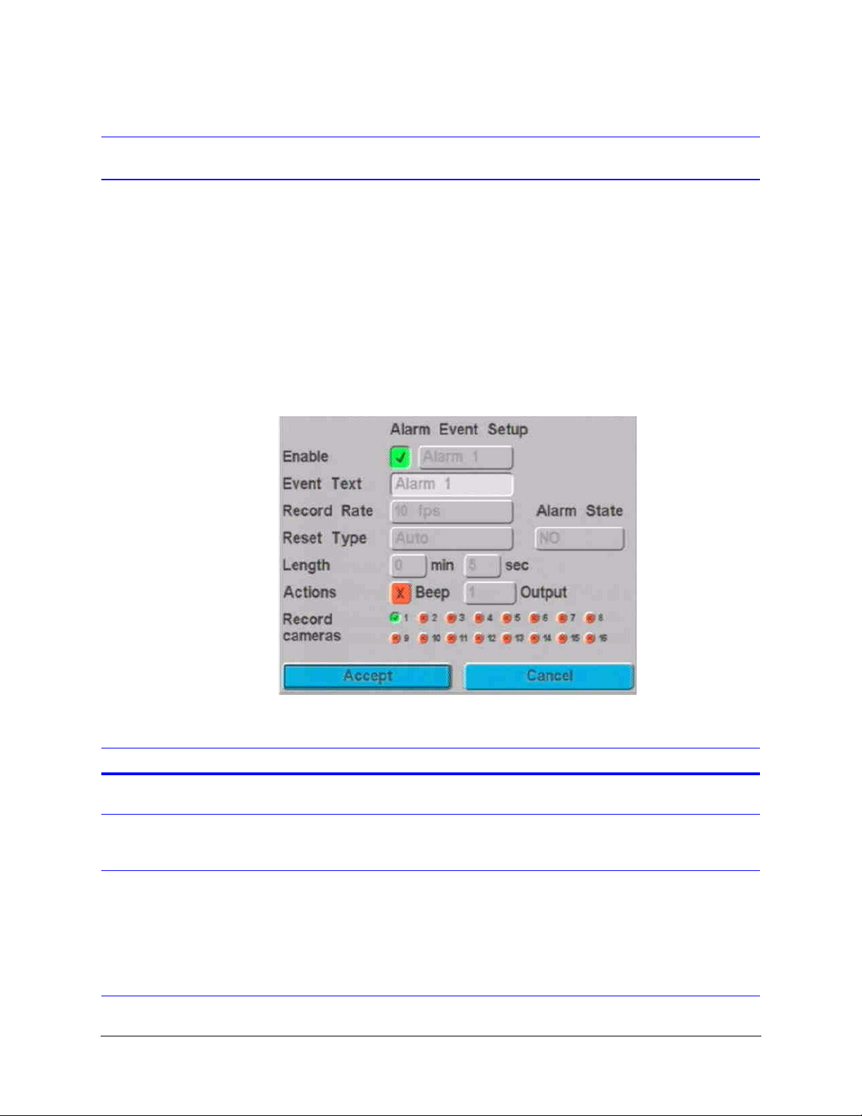
Setting Alarm Events
The HRDV16 has 16 hardwired alarm inputs on the back of the unit. The HRDV8 has 8. For
each input you must indicate how you want the system to handle alarm events. Alarm
events can be triggered by external alarm devices (for example, text insertion, motion
detection, a panic button).
For more information on how the system reacts to alarm events, see Event Handling on
page 58. For more information on activating a hardwired alarm from an HRDV to a panic
button in a remote location, see Setting Alarm Events, page 37.
HRDV Reference Guide
Access the Alarm Event Setup screen as follows: MENU
Events. Figure 8-2 displays.
Figure 8-2 Alarm Event Setup Screen
The following table describes the fields on the Alarm Event Setup screen.
Field Description
➤ Event Recording ➤ Alarm
Enable Enable or disable the Alarm Event function for up to 16 alarm events (8 for the
HRDV8). Enable this field to change the settings on the screen.
Event Text Assign a title to each Alarm event. This text is used to title the video clip (see Event
Report Criteria on page 117) when reviewing events (see Running a Report on
page 120).
Record Rate Specify the record rate, in fields per second (fps), to be recorded by each camera.
.1, .2, .5, 1 to 16 (10 is default), 20 to 60 in increments of five.
Note The total number of fps that can be recorded by all 16 cameras cannot add
up to more than 60 fps for NTSC or 50 fps for PAL. For the HRDV8, the total
fps that can be recorded by all 8 cameras cannot add up to more than 30
fps for NTSC or 25 fps for PAL.
Rev 1.00 37 Document 900.0261
04/05
Page 56
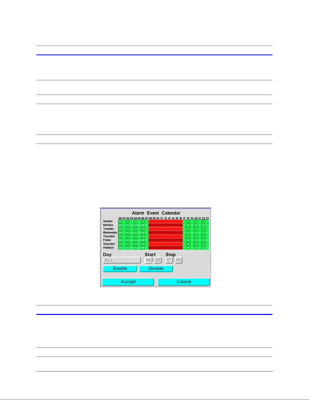
Alarm Setup
Field (Cont’d) Description
Reset Type There are two reset options:
Auto. Alarm inputs automatically reset immediately after the alarm event.
Timed. Alarm inputs reset after the time specified in the Length field.
Alarm State You must specify whether each contact is normally open (NO) or normally closed
(NC).
Length The length of time before the alarm inputs are reset.
Actions How the HRDV16/8 reacts to an alarm event. Options are:
Beep. The HRDV16/8 beeps when an alarm event is detected.
Output. The HRDV16/8 triggers an alarm output contact (activates an external
light, bell, and so on).
Record cameras Enable alarm event recording for up to 16 cameras.
Setting Alarm Event Recording Calendar
Use this screen (MENU ➤ Event Recording ➤ Alarm Event Calendar) to specify when
alarm event recording is active—similar to the timelapse recording (see Setting Simple
Timelapse Mode With Motion Detect Enabled on page 65). Figure 8-3 displays.
Figure 8-3 Alarm Event Calendar Screen
The following table describes the fields on the Alarm Event Calendar screen.
Field Description
Day Options are:
Sunday to Saturday. Program each day individually
ALL. Program all the days of the week the same
Holidays. Program holiday scheduling
Green areas indicate enabled
recording times.
Red areas indicate disabled
recording times.
Start Enter the time you want alarm event recording to begin.
Rev 1.00 38 Document 900.0261
04/05
Page 57
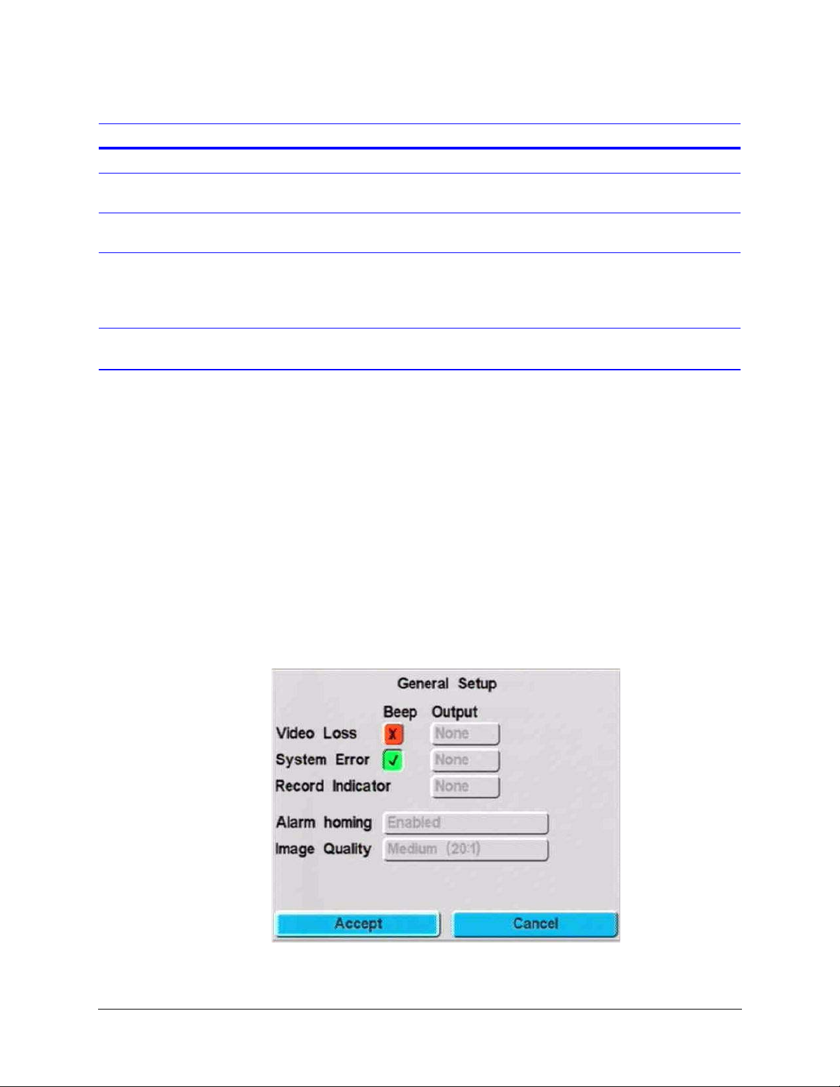
HRDV Reference Guide
Field Description
Stop Enter the time you want alarm event recording to end.
Enable After you have set up the start and stop times for the desired days, select Enable,
then Accept to confirm your settings.
Disable Select Disable, then Accept to deactivate alarm event recording for the days and
times set.
Alarm Homing
You can install a panic button (for example, in a subway station) and run a wire from the
panic button to the remote monitoring unit to provide a ground to an alarm input of the
HRDV unit.
When the panic button is pressed and the alarm input detects an open or closed condition
(depending on how you configure the alarm input) the main video monitor automatically
switches to a live display of the camera(s) set to record the alarm. If multiple cameras are
set to record a multi camera screen appears—quad (2 x 2), nine (3 x 3), or 16 (4 x 4).
When an alarm is removed, the monitor returns to a multiscreen view of all live cameras.
If a single alarm occurs and you are viewing the first alarm camera view and a second alarm
then occurs on a different camera, the monitor shows a multiscreen display that includes
both alarming cameras.
To enable this feature:
1. Access the General Setup screen (MENU
➤ Event Recording ➤ General Setup).
2. Enable the Alarm homing field.
Rev 1.00 39 Document 900.0261
04/05
Page 58
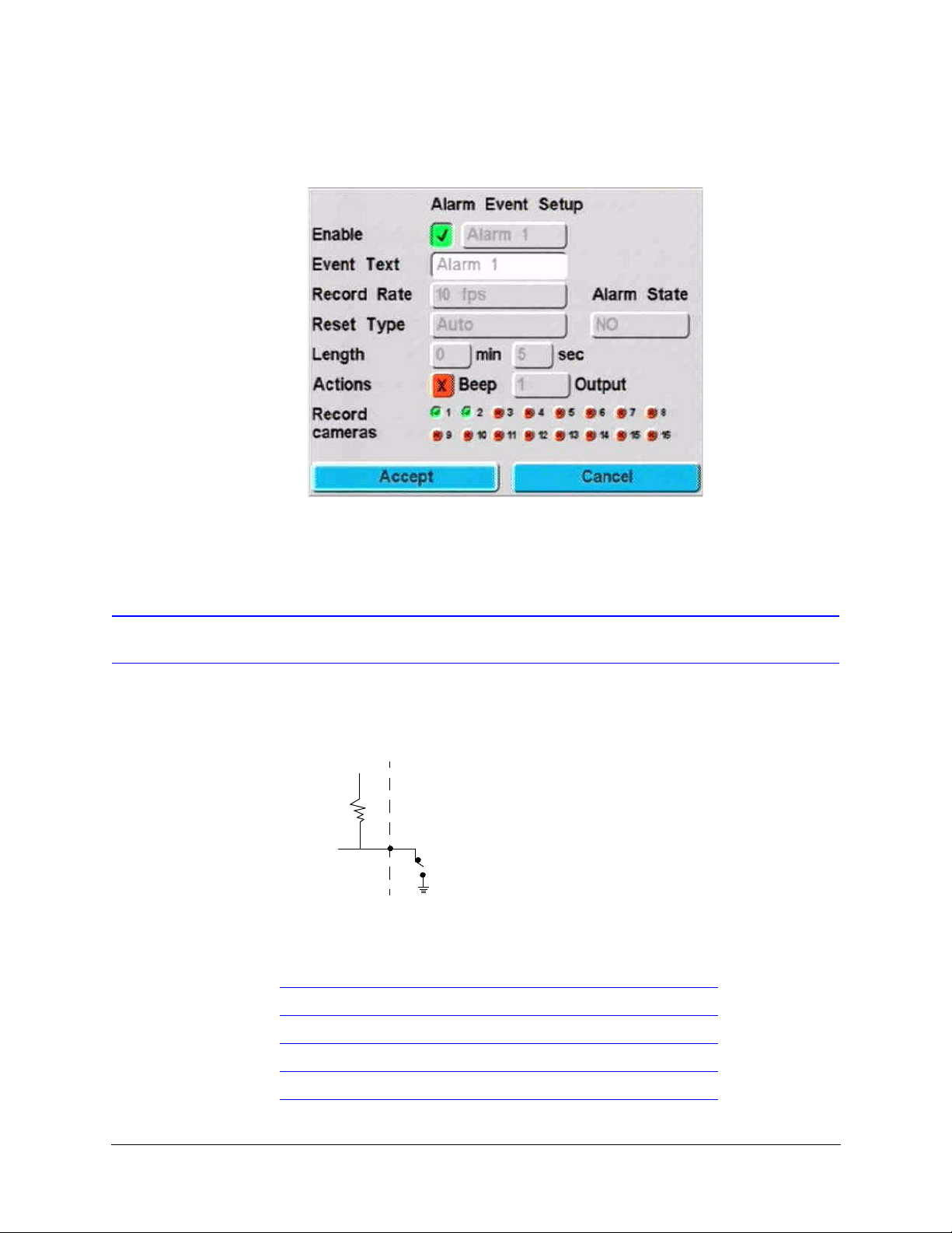
Alarm Setup
3. Enable the individual alarm inputs and program which cameras you want to record on
the Alarm Events screen (MENU
➤ Event Recording ➤ Alarm Events).
4. Connect the panic button to the appropriate alarm input.
Alarm I/O Connection
To set NO/NC, see Alarms.
+5 VDC
Detector
Internal to HRDV
The following table describes the 25-pin Alarm I/O connector pinout.
Alarm Inputs
Normally Closed (NC).
If open, alarm is
detected.
10K
Normally open (NO).
If closed, alarm is
detected.
Alarm output
+5 VDC = Alarm
GND = No Alarm
Exception:
Record indicator
+5 VDC = Record
GND = Stopped
External to HRDV
(Add this functionality
yourself)
PIN Definition
1 Alarm In 1 Alarm Inputs 1 to 16, TTL Levels
2Alarm In 3
3 Ground
Rev 1.00 40 Document 900.0261
04/05
Page 59

4Alarm In 6
5Alarm In 8
6 Alarm In 9 HRDV16 only
7 Alarm In 11 HRDV16 only
8 Ground
9 Alarm In 14 HRDV16 only
10 Alarm In 16 HRDV16 only
11 Reserved
12 Alarm Out 1
13 Alarm Out 2 Alarm Outputs 1 to 4, TTL Levels
14 Alarm In 2
15 Alarm In 4
16 Alarm In 5
HRDV Reference Guide
17 Alarm In 7
18 Ground
19 Alarm In 10 HRDV16 only
20 Alarm In 12 HRDV16 only
21 Alarm In 13 HRDV16 only
22 Alarm In 15 HRDV16 only
23 +5 VDC +5 Volts DC, 100 mA
24 Alarm Out 3
25 Alarm Out 4
Rev 1.00 41 Document 900.0261
04/05
Page 60

Alarm Setup
Rev 1.00 42 Document 900.0261
04/05
Page 61
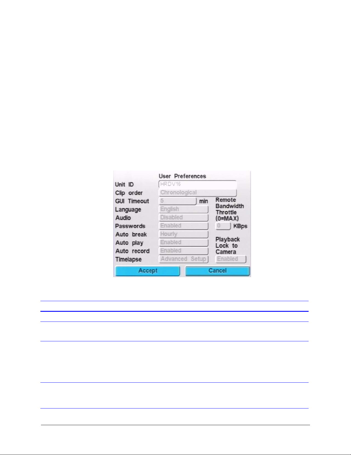
User Preferences
This chapter describes how to set user preferences that apply to the whole system.
Use the User Preferences screen to set preferences that apply to the whole system:
MENU
➤ System Setup ➤ User Preferences. Figure 9-1 displays.
Figure 9-1 User Preferences Screen
9
The following table describes the fields on the User Preferences screen.
Field Description
Unit ID Specify the unit name. Can be up to 14 alphanumeric characters.
Clip order Specify how stored video clips are listed. Options are:
Reverse chronological, chronological (default)
GUI Timeout Set up the Graphical User Interface (GUI) inactivity time out, in minutes. Options
are:
0 to 240. Default is five minutes. After this amount of inactivity time you will be
automatically logged out.
When set to 0, the GUI never times out.
Language Choose to have the text on all HRDV screens appear in the language of your
choice. Options are:
English (default), French, Italian, Spanish, Dutch, Portuguese
Rev 1.00 43 Document 900.0261
04/05
Page 62

User Preferences
Field (Cont’d) Description
Audio Enable or disable audio recording.
Passwords Enable or disable the requirement for use of user names and passwords to log on
to the HRDV16/8.
Caution If disabled, there will be no prompt for user name and
password when logging on. Your system will not be secure. We
recommend that you always enable this feature.
Autobreak Break Timelapse recording into individually searchable video clips. Options are:
15 minutes
Hourly. (recommended setting for timelapse recording)
Daily. A single daily timelapse clip for each day starting at 12:00 midnight
Disabled. One continuous single clip
Autoplay Options are:
Enabled. When a report or search is done that lists more than one video clip and
a video clip is selected to play back, the HRDV automatically plays all clips in
sequence. Allows you to put the HRDV into fast forward turbo mode to advance
rapidly through the selected video clip. At the end of the clip, the HRDV
automatically advances to the next clip. This feature works best when Playback
Lock to Camera is enabled.
Disabled. The HRDV only plays back one clip at a time.
Autorecord Options are:
Enabled. The HRDV automatically puts itself in record mode after 60 seconds if
recording is inadvertently disabled by an operator (recommended setting).
Disabled.The HRDV will stop recording until manually reset if recording is
inadvertently disabled by an operator.
Timelapse There are two timelapse modes available: simple setup and advanced setup.
Simple Setup Uses programmable, calendar based timelapse recording scheduling. Timelapse
clips are recorded in the timelapse hard disk partition. Events (motion detection,
text, or switch) generate event files that are written to the hard disk event partition.
You may also specify a business schedule (for example: Monday to Friday, 8 a.m.
to 5 p.m.) to record timelapse and then only record events in the alternate times.
To set the desired Timelapse Recording schedule, see Setting Up Simple
Timelapse, page 62.
Advanced Setup Allows you to program both normal (day) and alternate (night) recording
schedules. In addition to the Simple mode recording features, Advanced mode
also allows you to program individual fps rates for each camera.
To set an advanced normal recording schedule, see Setting Advanced Timelapse
Mode, page 68.
To set an advanced alternate recording schedule, see page 71.
Rev 1.00 44 Document 900.0261
04/05
Page 63

Field (Cont’d) Description
HRDV Reference Guide
Remote Bandwidth
Throttle
Playback Lock to Camera Options are:
Regulates network bandwidth usage. A bandwidth throttle control restricts
network bandwidth usage from 1 to 250 KBps (in 1 KBps increments). Options are:
1 to 250 KBps
MAX. Wide open operation
0. Disables the throttle mechanism
Note Bandwidth restriction can lower the fps when you view clips remotely.
Enabled. When you play back a video clip that has recorded multiple cameras at
the same time and you select one camera to review and then press the left or right
arrow to jump to the next or previous video clip, you will stay locked on that one
camera.
Disabled. During playback of video clips from multiple cameras, the monitor
reverts to a multiscreen display of all the cameras recorded.
Rev 1.00 45 Document 900.0261
04/05
Page 64

User Preferences
Rev 1.00 46 Document 900.0261
04/05
Page 65

Storage Setup
You can connect up to seven storage devices to the HRDV16/8. These include a variety
of IDE and SCSI devices:
• Up to four internal IDE hard drives
• Up to three SCSI devices (see Connecting the HRDV16/8 to Peripherals on page
15).
This chapter describes how to:
• Calculate required disk space
• Calculate how many hours the disk will record
• Calculate event space required
• Configure storage setup
• View current hard drive capacity
• Add or replace a disk drive
• Restore the file system to its original state
• Perform a Holdup setup
10
Configuring Storage Setup
On the Disk menu, you can set up, configure, and check the status of the disk drives used
to store your digital video. When a disk is installed and operating in your HRDV16/8, a
button showing the disk information automatically highlights on the Disk menu. The
number of highlighted buttons depends on the number of additional drives that are
installed in your system. If you have purchased additional removable media drives, you
will also be able to check their status using the Disk status buttons.
Rev 1.00 47 Document 900.0261
04/05
Page 66
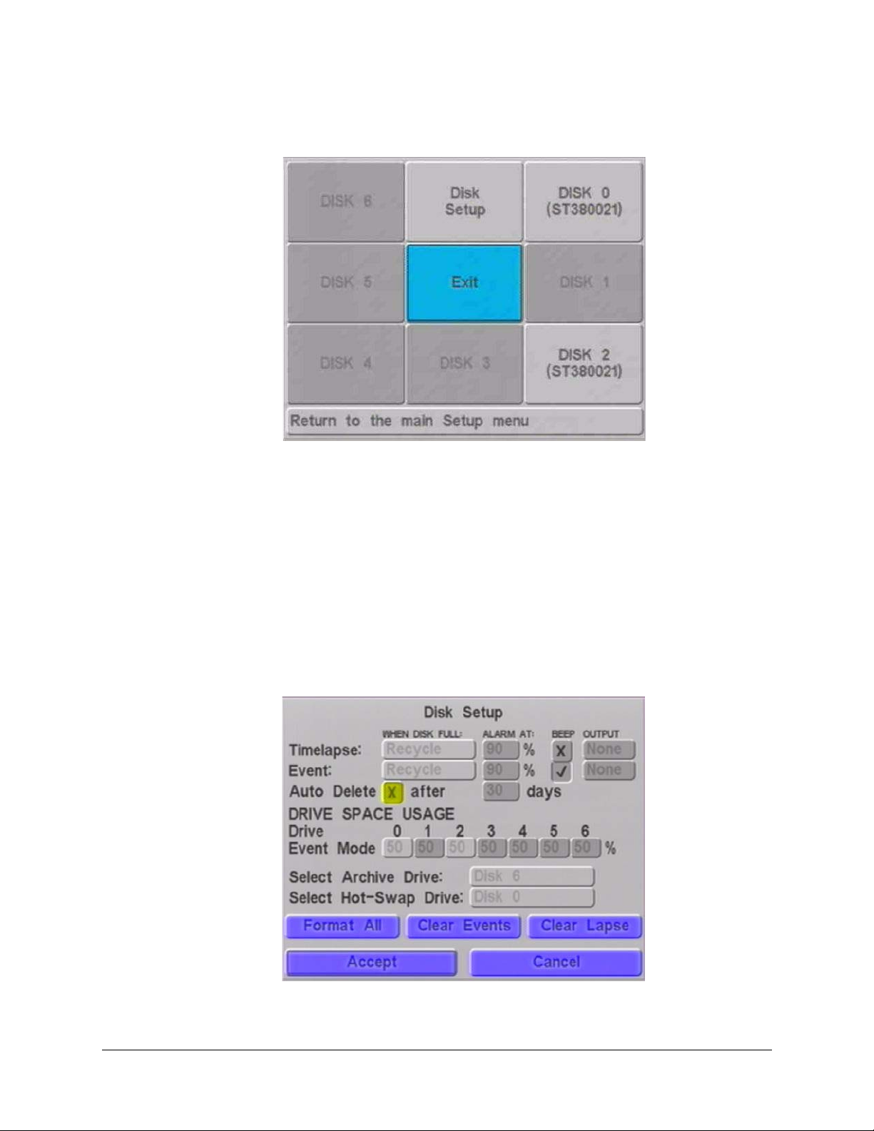
Storage Setup
Figure 10-1 Disk Menu
Use the Disk Setup screen to control the way data will be saved to your disk drives.
Specifically, you can:
• Determine which drives are recognized by the system
• Set parameters related to the file system, such as:
• Timelapse/event partitioning
• Alarm when a drive exceeds a certain capacity (percentage)
• Archive and hot-swap drives
• Reformat an Archive drive
Access the Disk Setup screen as follows: MENU
Figure 10-2 displays.
Figure 10-2 Disk Setup Screen
➤ Storage Setup ➤ Disk Setup.
Rev 1.00 48 Document 900.0261
04/05
Page 67

HRDV Reference Guide
The following table describes the fields on the Disk Setup screen.
Field Description
When Disk Full Determines what the system does when the timelapse and event portions of the
hard drive storage space are full. Options are:
Stop. Stops recording.
Recycle. Start at the beginning again, overwriting oldest images.
Alarm At When the storage space reaches this percentage, the HRDV16/8 sends an alarm.
Beep If enabled, the HRDV16/8 beeps when the disk is full.
Output If enabled, the HRDV16/8 sends a signal to the specified alarm output when the
disk is full. Options are:
1 to 4, None
Auto Delete Options are:
1 to 365
Caution If enabled, the HRDV16/8 automatically deletes stored data
after the number of days selected.
Event Mode Allocate a percentage of the drive capacity for each drive installed. The balance of
the capacity is allocated to timelapse.
Note Set the drive capacity to 100% if you only use Event mode (and not
Timelapse).
Select Archive Drive Allocate one installed hard drive as an archive drive.
To program an automatic transfer of selected clips to an archive drive, see Setting
Reports to Run Automatically, page 122.
For more information on archiving video clips, refer to the HRDV RAS User Guide.
Select Hot-Swap Drive Allocate one installed hard drive to be a Swap drive. A Swap drive can be removed
and replaced with another drive while the unit is powered on. This allows easy
archiving of large amounts of data. For example, a weekly archive could be
managed using seven large drives, replaced on a daily basis and rotated weekly
using the Swap function.
To set up the Swap feature, select a drive number as your Swap drive, then press
Enter.
Note All drives being swapped into the unit must have the same ID. To avoid
possible data loss, it is recommended that you use only one regular disk
on your system to record when using the Swap feature. A second drive for
archiving is allowable when using Swap. When the archive drive is
designated as the Swap drive, the single disk restriction does not apply.
Format All Reformats drives.
Caution This action deletes all of the data on your drives.
Clear Events Deletes all of the events on your drives.
Clear Lapse Deletes all of the timelapse data on your drives.
Rev 1.00 49 Document 900.0261
04/05
Page 68

Storage Setup
Calculating Disk Space Required
To determine how much disk space is required for storing timelapse and event data, use
the following two formulas and add the results together to get a total amount of disk space
needed.
Note The following calculations are for NTSC. For PAL, use the coefficient 1.49
instead of 1.26.
For timelapse:
For events: Image size x Record rate (fps) x number of seconds = Event disk space
For total timelapse
and events:
Total hours x Record rate (fps)
Image quality (compression)
In this example:
168 hrs x 5 fps
20
Event space x number of events per day x number of days = Total events disk space
In this example:
1
17,500
262,500 x 500 x 7 = 918,750,000 (or approximately 1 GB)
Timelapse disk space + total events disk space = Total disk space
In this example:
x 3 fps x 5 secs = 262,500 bytes
x 1.26 = Timelapse disk space
x 1.26 = 52.92 (approximately 53 GB)
53 GB + 1 GB = approximately 54 GB
for one week (168 hours) of timelapse and events recording.
1
one field is approximately 350 Kbps. Therefore, the stored image size is
field/compression = 350 K/20 = 17,500.
Rev 1.00 50 Document 900.0261
04/05
Page 69

HRDV Reference Guide
Calculating How Many Hours the Disk Will Record
To determine how long a disk(s) will last, use the following formula:
Disk size x Image quality (compression) / Record rate (fps)
1.26
For example:
(100 GB x 20) /5
1.26
= 317 hours (or approximately 13 days)
Calculating Event Space Required
To determine how much disk space is required for storing event data, use the following
formula:
For events: Image size x Record rate (fps) x number of seconds = Event space
Event space x number of events per day x number of days = Total events
For example:
= hours
17,500 x 3 fps x 5 seconds = 262,500 bytes
262,500 x 500 x 7 = 918,750,000 or approximately 1GB
Viewing Current Hard Drive Capacity
Use the Disks screen to see:
• How your current hard drive capacity is proportioned
• How full your drives are
• Whether the drive is degrading and becoming unreliable if S.M.A.R.T. (Self-Monitoring
Analysis & Reporting Technology) is running on your system. See Appendix F,
S.M.A.R.T. for more information.). S.M.A.R.T. is available with HRDV V2.12T and later.
Access the Disks screen as follows: MENU
appropriate disk. A screen similar to Figure 10-3 displays.
Rev 1.00 51 Document 900.0261
➤ Storage Setup ➤ Disks, then highlight the
04/05
Page 70
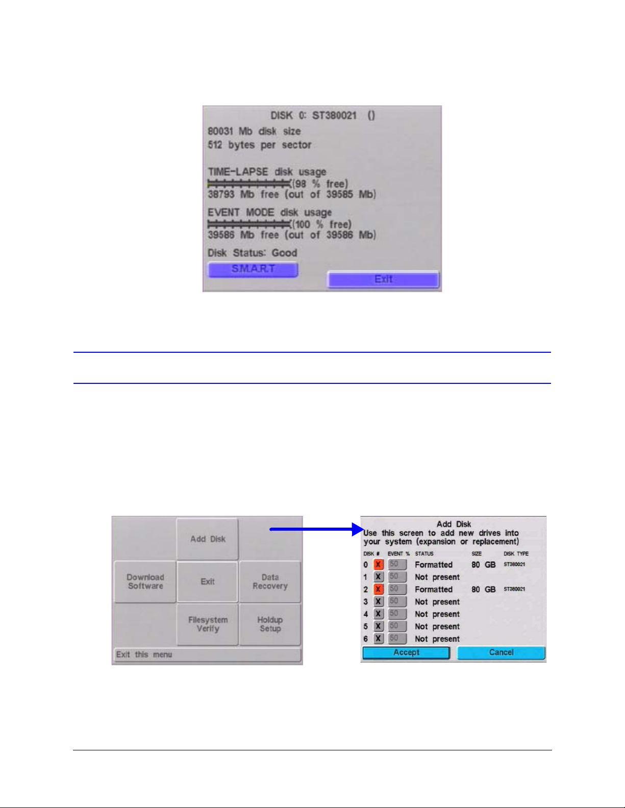
Storage Setup
Figure 10-3 Disk Status Screen
Adding or Replacing a Disk Drive
With HRDV V2.0 and later, you can:
• Add further drives for increased storage capacity while preserving video stored on the
original drive(s)
• Re-partition an individual disk drive (video on that drive is lost)
• Replace a single faulty drive without affecting other disk drives
To view this option, access the Add Disk screen: MENU
Utilities ➤ Add Disk.
➤ System Setup ➤ System
Rev 1.00 52 Document 900.0261
04/05
Page 71
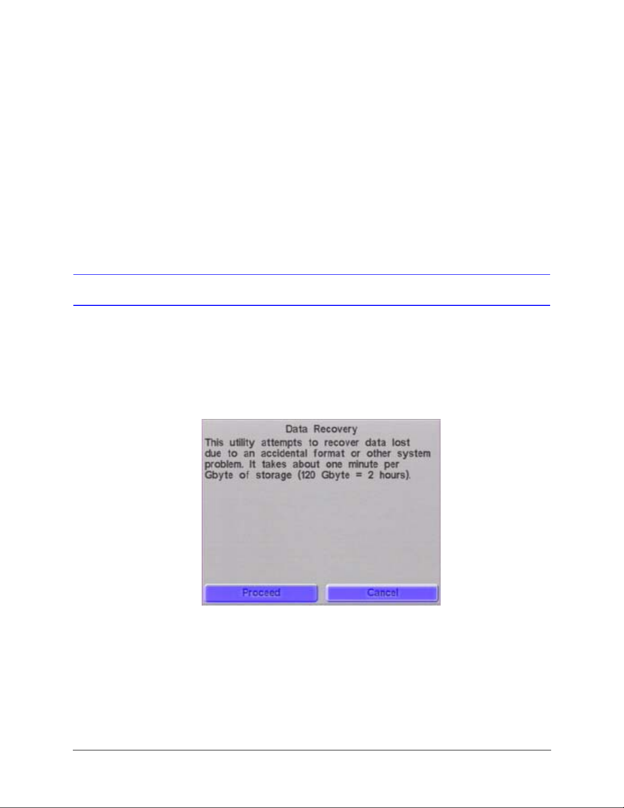
Data Recovery
HRDV Reference Guide
To add a new drive:
1. Power down the HRDV unit and install the new drive. Refer to the HRDV16/8 Internal
Drive Upgrade Guide for complete details. This document can be found on the
Honeywell web site at www.honeywellvideo.com.
2. Power up the HRDV unit and go to the Add Disk screen (MENU
System Utilities
3. Enable only the new drive you have added and set the desired Event percentage.
4. Accept your changes to exit this screen. The new drive is now operational.
5. Exit Menu mode and ensure recording is enabled.
Use this screen when you want the system to attempt to restore the file system to its original
state (for example, due to an inadvertent Format All, Format Timelapse, or Format Event
command).
➤ Add Disk).
➤ System Setup ➤
You can also use this utility to attempt to recover disk drive data (timelapse video, event
video, text data) if a system problem occurs.
Figure 10-4 Data Recovery Screen
Rev 1.00 53 Document 900.0261
04/05
Page 72
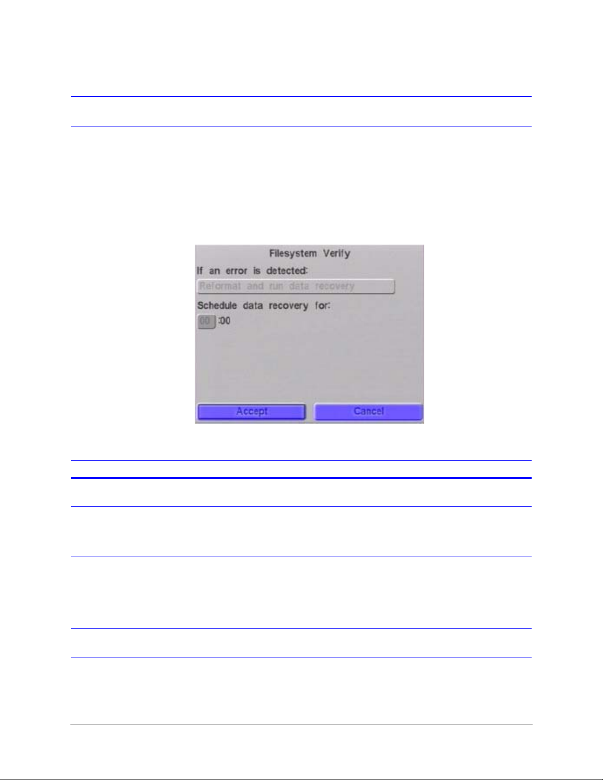
Storage Setup
Verify File System
The FileSystem Verify feature checks the integrity of the file structure on the hard drive. It
runs automatically on every power cycle. If an error is detected, the HRDV will perform one
of three actions, depending on your selection:
• Reformat the drive(s)
• Reformat the drive(s) and run a data recovery
• Reformat the drive(s) and schedule a data recovery
Figure 10-5 FileSystem Verify Screen
The following table describes the fields on the FileSystem Verify screen.
Field Description
Reformat only If an error is detected, the HRDV automatically reformats the drive and restarts
recording to the beginning. All the data on the drive is lost.
Reformat and run data
recovery
Reformat and schedule
data recovery
Schedule data recovery
for
If an error is detected, the HRDV automatically reformats the drive and then
immediately attempts a data recovery (restores the file system to its original state).
Note Running a data recovery causes some data on the drive to be overwritten.
If an error is detected, the HRDV automatically reformats the drive and restarts
recording to the beginning. The system attempts a data recovery (restores the file
system to its original state) at the time you set in the Schedule data recovery for
field.
Note Running a data recovery causes some data on the drive to be overwritten.
Set the time you wish the HRDV to attempt a data recovery. We recommend that
you schedule your data recovery for a period of little activity (for example, at night).
Rev 1.00 54 Document 900.0261
04/05
Page 73
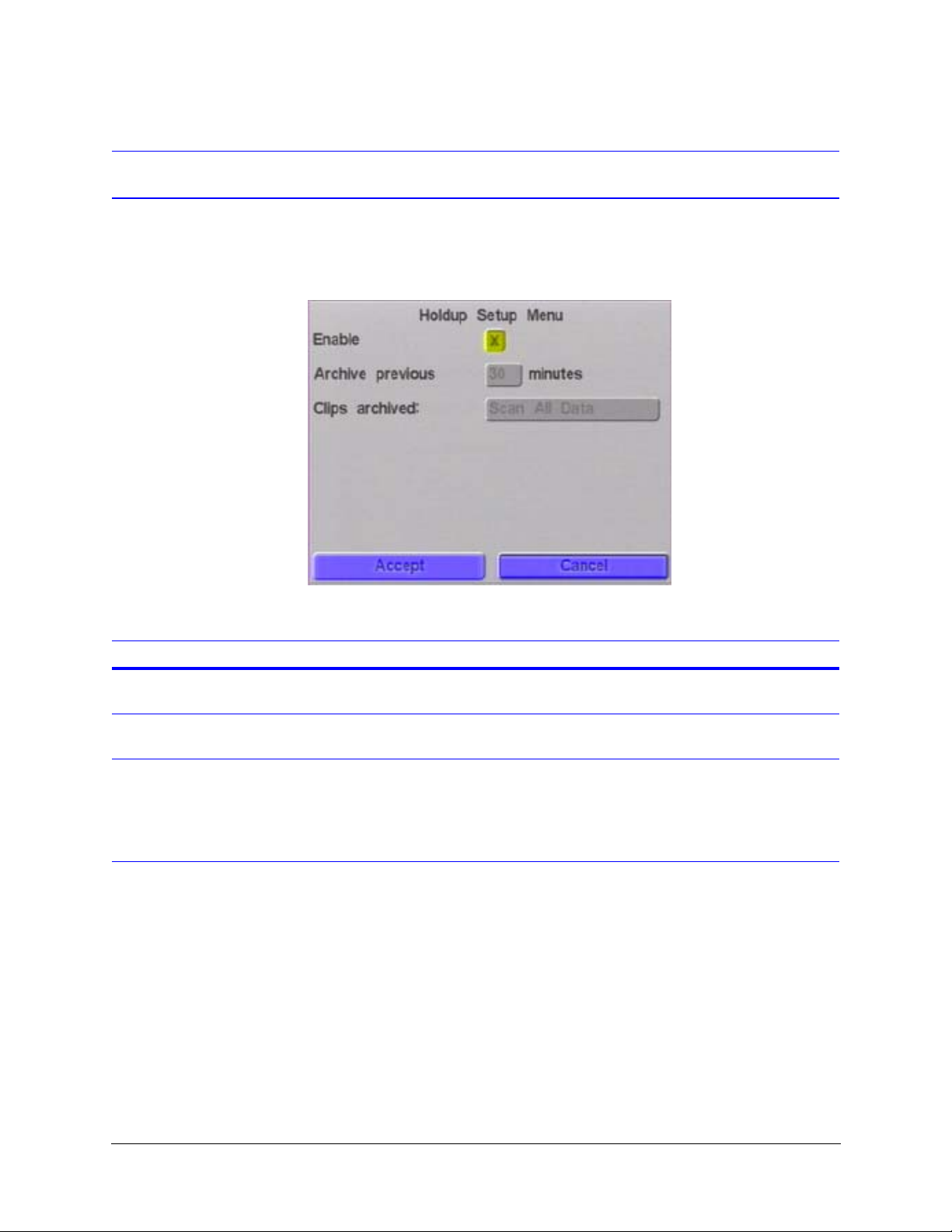
Holdup Setup
HRDV Reference Guide
The Holdup Setup feature checks the integrity of the file structure on the hard drive. It runs
automatically on every power cycle.
Figure 10-6 Holdup Setup Screen
The following table describes the fields on the Holdup Setup screen.
Field Description
Enable Enables or disables (default) the Holdup Setup feature. To make changes on the
screen, this field must be enabled.
Archive previous Select the number of minutes (from 1 to 60) previous to the Holdup that will be
archived.
Clips archived Select the type of clips to be archived as a result of the Holdup Setup. Options are:
Scan All Data. Scans all recorded clips in the specified time frame.
Scan Timelapse. Scans only timelapse video in the specified time frame.
Scan Events. Scans only event clips in the specified time frame.
Rev 1.00 55 Document 900.0261
04/05
Page 74

Storage Setup
Rev 1.00 56 Document 900.0261
04/05
Page 75
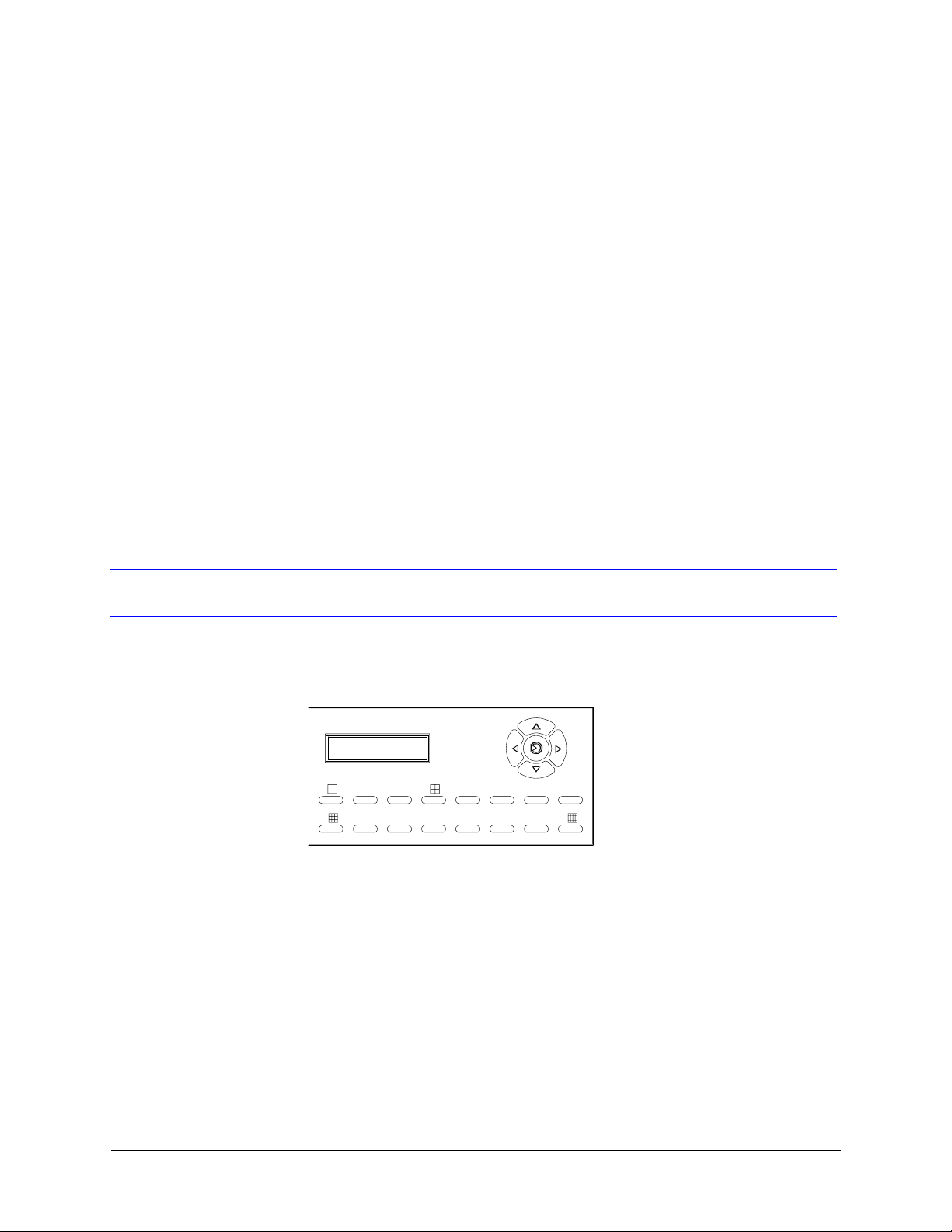
Recording Considerations
The HRDV16/8 is a duplex recorder; you can play back images without stopping the
recording. However, recording stops if you enter the Programming mode to change
system setup configurations.
This chapter:
• Describes how to start and stop recording
• Provides considerations for timelapse and event recording
Starting and Stopping Recording
To start recording video:
1. Press REC (left arrow) on the HRDV16/8 front panel.
11
HRDV16
12345678
9 10111213141516
2. Select a User ID (camera buttons 1 to 16). The default User ID is 1.
3. Enter your user name and password when prompted (camera buttons 1 to 4 only).
Press Enter. (Default password is 1234).
As soon as you enter a valid user name and password, the unit starts recording
according to the values entered in Program mode.
To stop recording:
1. Press REC.
2. Enter your User ID and password and press Enter.
MENU
REC PLAY
FUNCTION
Rev 1.00 57 Document 900.0261
04/05
Page 76

Recording Considerations
Timelapse and Event Recording Considerations
Timelapse recording and event recording settings are independent. For example, when an
event triggers an event recording, the system may be set to record at a higher frame rate
and/or at a lower compression rate. An event may be programmed to reset automatically
or it may be programmed to reset only when the operator activates the alarm reset input.
After the event is reset, the normal timelapse recording mode or pre-event recording mode
starts again (see Timelapse Recording Setup on page 61 and Motion Event Recording
Setup on page 77, respectively).
During system setup there are two different modes that tell the HRDV16/8 what to do when
the recording space on the disk is full (see Storage Setup on page 47):
• Recycle mode is similar to rewind and re-record for VCR tapes. In this mode the
operator is not warned when old data is being overwritten by new data.
• Stop means that the HRDV16/8 stops recording when the disk is full. In this case the
operator sees a blue screen with a text message on the video monitor with a warning
that the system needs to overwrite old data.
You may use the cursor controls to signal the system to re-record over old data, or to
stop recording to allow you time to archive data to another storage device before it is
lost.
Event Handling
Examples A Motion event may cause the camera that detected the motion to be recorded at a high
To calculate how much disk space is required for storing timelapse data, see Calculating
Disk Space Required, page 50.
Any event causes the HRDV16/8 to enter event mode. The HRDV16/8 automatically
detects:
• A full hard drive
• A system error
• Loss of video signal from any enabled camera
• Text, motion, and alarm events as defined in the Event Recording screens (see Motion
Event Recording Setup on page 77)
The HRDV16/8 can also operate as an event recorder (see Chapter 14, Pre-Event Recording
Setup).
When an event is triggered, the event recording or event action specified in Program mode
is started.
speed and low compression.
When the video signal of an enabled camera is lost, the event may trigger a beeping noise
or a text output to the monitor.
Rev 1.00 58 Document 900.0261
04/05
Page 77

HRDV Reference Guide
There are two reset types that determine how events are cleared:
• In automatic mode, the event is reset as soon as the input signal returns to inactive.
• In timed mode, the alarm is active for the interval set. In this case, after the event timer
expires, the event must be deactivated before another timed mode alarm event can
be recognized.
Example If a door opening triggers an alarm event that lasts for 30 seconds, the event mode turns
off after 30 seconds, even if the door is still open. A timed alarm event cannot be triggered
again until the door is closed.
Text, alarm, and motion events can cause an event video clip to be recorded. An event
video clip records:
• The starting time and date of the event
• The type of event
• The video images that were recorded during the event
If the video camera title was being displayed and/or a Text Insertion port was set to display
text when the video clip was recorded, that text is also recorded along with the event video
clip.
During video clip recording, the HRDV16 can record up to 60 fields per second (fps) for
NTSC or 50 fps for PAL. The HRDV8 can record up to 30 fps for NTSC or 25 fps for PAL.
Normally you set up each event so that the maximum recording rate is not exceeded during
a single type of event. However, there could be times when multiple events occur at the
same time. In that case, the HRDV16/8 may be sent a recording request that would cause
the maximum recording rate to be exceeded. As events occur, each event is placed in a
queue and recorded at the rate set for it in Setup mode. As the unit nears the maximum
number of fps, each additional event causes the maximum recording rate to be exceeded.
This causes the HRDV16/8 to drop the rate at which all currently active events are being
recorded. The benefit is that all active events are recorded, even if they are forced to record
at a slightly lower recording rate.
Example You are using a PAL system and a text event is detected that causes camera 1 to be
re cor ded at 25 fps. An alar m in put causes camera 2 to be rec ord ed at 25 fps. Then a mo tio n
event is triggered that would normally cause camera 3 to be recorded at 20 fps, exceeding
the PAL maximum recording rate of 50 fps. The HRDV16/8 drops the recording rate of the
first two events to 12.5 fps and starts recording the third event at 12.5 fps. If further events
occur, the HRDV16/8 drops the recording rate, as needed, for all currently active events so
that there is some recording capacity available for the additional events.
To calculate how much disk space is required for storing event data, see Calculating Disk
Space Required, page 50.
Rev 1.00 59 Document 900.0261
04/05
Page 78

Recording Considerations
Rev 1.00 60 Document 900.0261
04/05
Page 79
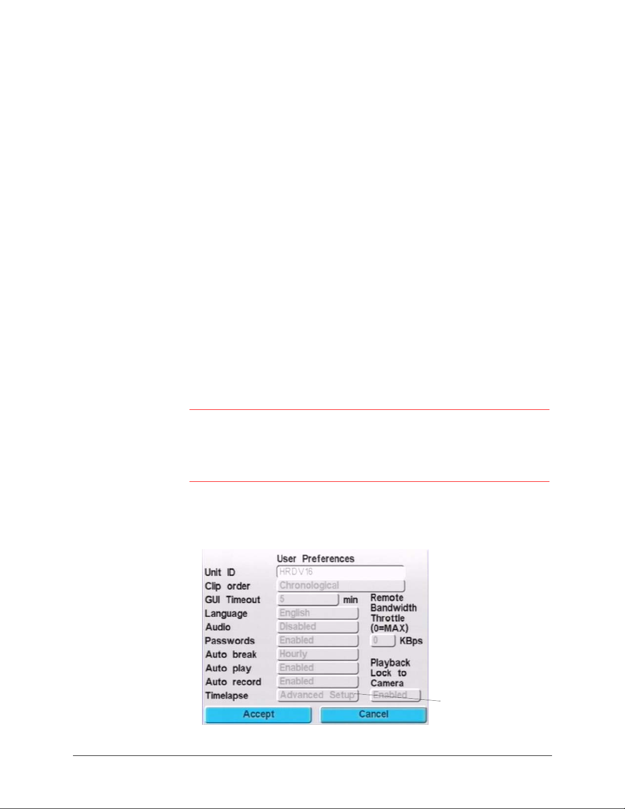
Timelapse Recording Setup
Timelapse video clips are stored in the timelapse disk drive partition. This chapter
describes how to record and store timelapse clips only.
It is possible to schedule your HRDV to store both timelapse clips and event clips. Events
(motion, text, or alarm) generate event files that are written to the event partition. To store
event clips (for example, motion or text) in the event disk drive partition, see Chapter 13.
This chapter describes how to use the timelapse settings to:
• Select the global record rate and compression setting for timelapse recording
• Set the recording times for each day of the week
• Assign settings for up to ten holidays
• Set simple and advanced Timelapse mode
• Enable motion detect operation for timelapse clips
Caution If you use your HRDV16/8 as a combined timelapse/event recorder,
the event recording settings override the timelapse settings when an
event is detected. When the system detects an event, the event
recording settings are used instead. See Pre-Event Recording Setup
on page 83.
12
There are two timelapse modes available: simple and advanced. To select simple or
advanced timelapse mode, go to the User Preferences screen (MENU ➤ System Setup
➤ User Preferences).
Select Simple or Advanced
Rev 1.00 61 Document 900.0261
04/05
Page 80
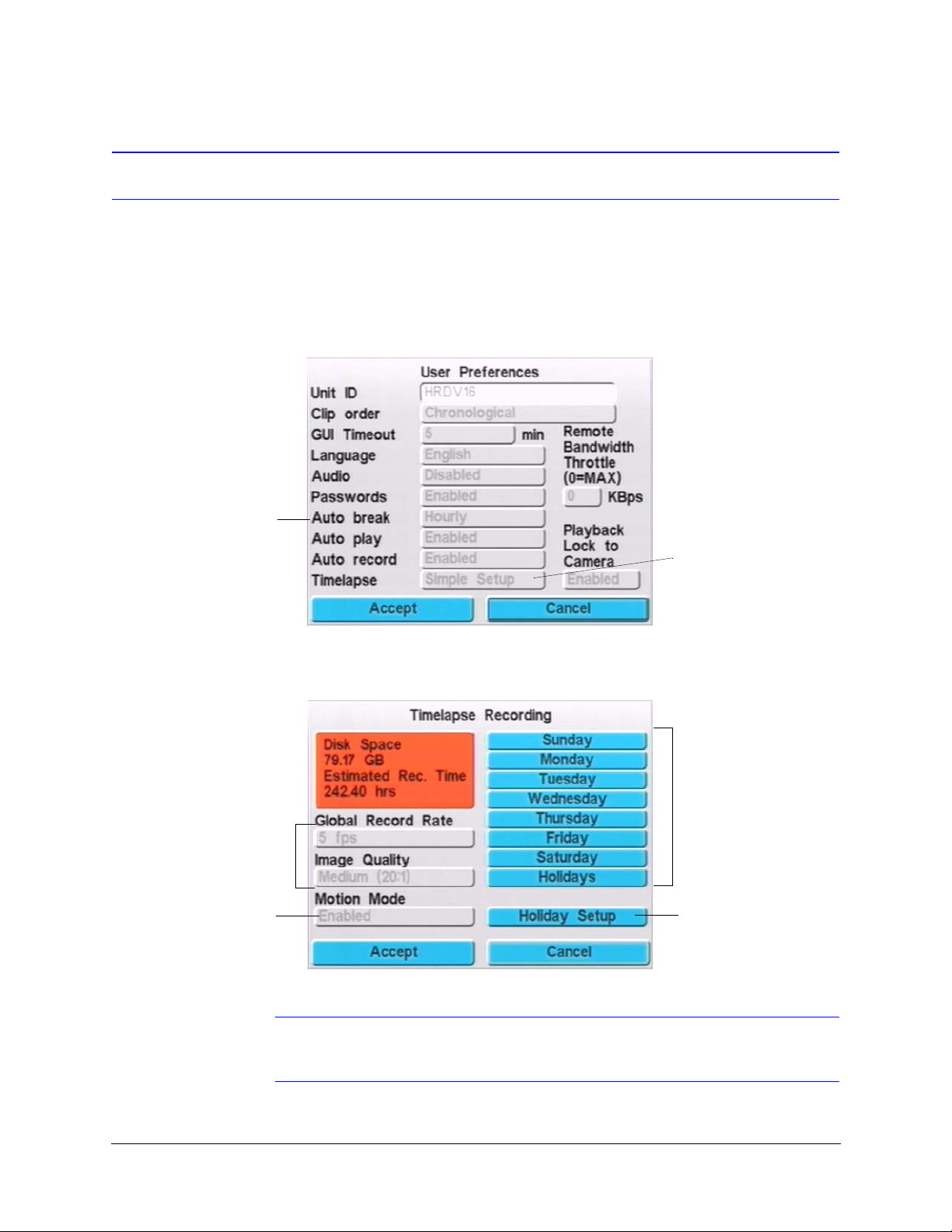
Timelapse Recording Setup
Setting Up Simple Timelapse
The Simple Timelapse mode allows you to set the HRDV16/8 for 24 hour, seven days a
week timelapse recording.
To store timelapse clips in the timelapse partition of the hard disk only—that is, motion
detection is not enabled— do the following:
1. Enable timelapse for Simple Setup (MENU
We recommend that
you enable Autobreak.
Timelapse clips will be
separated into
searchable hourly,
daily, or 15 minute
chunks.
➤ System Setup ➤ User Preferences).
Set to Simple Setup
2. Set the record rate and image quality (MENU
Displays disk storage
recording to record rate and
image quality settings
Set global record rate
and compression
settings
Set this to disabled
for continuous
timelapse recording
➤ Timelapse Recording).
Figure 12-1 Timelapse Recording Screen
Set daily recording times
Set recording times
for holidays
Note When you adjust the record rate and/or the image quality, the approximate
record time changes in real time.
Rev 1.00 62 Document 900.0261
04/05
Page 81

HRDV Reference Guide
The following table describes the fields on the Timelapse Recording screen.
Field Description
Record Rate Set the global record rate, in fields per second. Each frame is a record of all the horizontal lines
of video and is made up of two fields. The total number of fields that can be recorded each
second by all 16 cameras cannot add up to more than 60 fields per second for NTSC (50 fps
for PAL).
For the HRDV8, the total fps that can be recorded by all 8 cameras cannot add up to more than
30 fps for NTSC (25 fps for PAL). Options are:
0, .1, .2, .5, 1 to 16 (5 is default), 20 to 60 in increments of five.
The lower the record rate, the longer you can record video before your storage disk is full.
Image Quality Set the global compression setting. The higher the quality, the slower the transmission of
images and the faster your storage disk fills. Options are:
High (10:1 or 15:1)
Medium (20:1 or 25:1) (default)
Low (30:1, 35:1, 40:1)
Very Low (45:1, 50:1)
Note The size of a single, high quality (10:1 compression), full frame color video image is
approximately 35 KB for NTSC.
Motion Mode Enables or disables Motion mode.
Note Timelapse clips are only recorded when motion is detected.
Sunday to Saturday Takes you to the selected screen where you set the recording times for that day. See Setting
Simple Timelapse Mode With Motion Detect Enabled.
Holiday Setup To set holiday recording times, you must first designate which holidays you want to enable.
See Setting Recording Times For Holidays.
Holidays Takes you to the holiday screen where you set holiday recording times.
Use the following table as a guideline when setting up the storage system and the capture
interval and compression ratios.
Tape type Hard drive
capacity
T120 VHS 10 GB 15:1 433,000
T120 VHS HD 23 GB 20:1 1,300,000
For more advanced calculations, see Calculating Disk Space Required, page 50.
3. Set the schedule for timelapse recording:
a. On the Timelapse Recording screen, select a day to enter your recording
schedule, then select Enter to display the recording schedule for that day.
Figure 12-2 shows examples of typical Simple Mode recording schedules for
Monday.
Compression
ratio
No. of images
per tape
Rev 1.00 63 Document 900.0261
04/05
Page 82
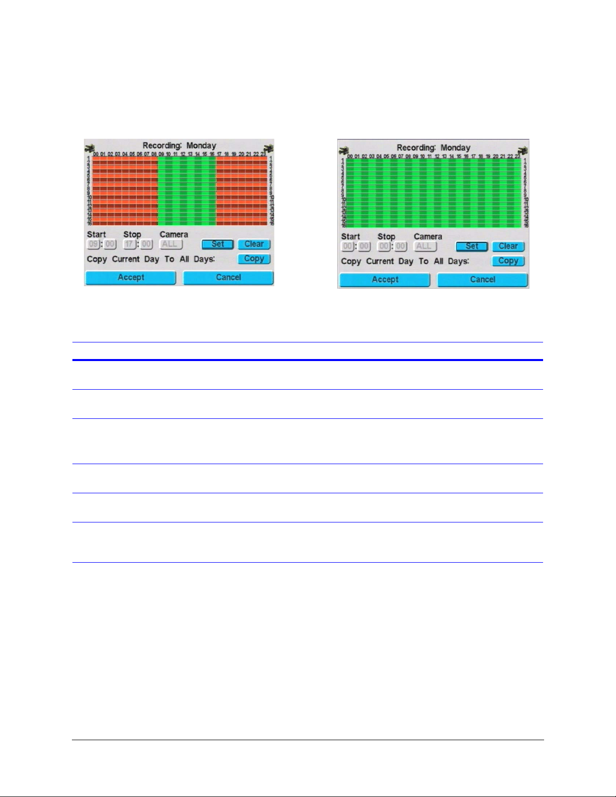
Timelapse Recording Setup
Figure 12-2 Timelapse in Simple Mode
8:00 a.m. to 5:00 p.m. Normal timelapse record
Event recording only during alternate hours
24 hour, motion activated timelapse record
Green areas indicate enabled recording
times.
Field Description
Start Set the start time range you want to set or clear for recording from the displayed
camera(s) and day’s screen.
Stop Set the stop time range you want to set or clear for recording from the displayed
camera(s) and day’s screen.
Camera Select individual or all connected cameras to which the recording schedule will be
applied. Options are:
1 to 16, ALL (default)
Set Apply the start and stop time parameters you have selected to the displayed
camera(s) and day for recording. Selecting Set displays the times as green.
Clear Remove the start and stop time parameters you have entered from the selected
day. Selecting Clear displays the times as red.
Copy Copy the current day’s display to all days. If you plan to record the same time for
every day of the year, this is the fastest way to do this. Note that when you view
other days’ record time, all will show the same recording schedule.
b. Enter the desired recording schedule, then select Accept.
c. Repeat for all the days of the week and all the cameras, as required.
Rev 1.00 64 Document 900.0261
04/05
Page 83
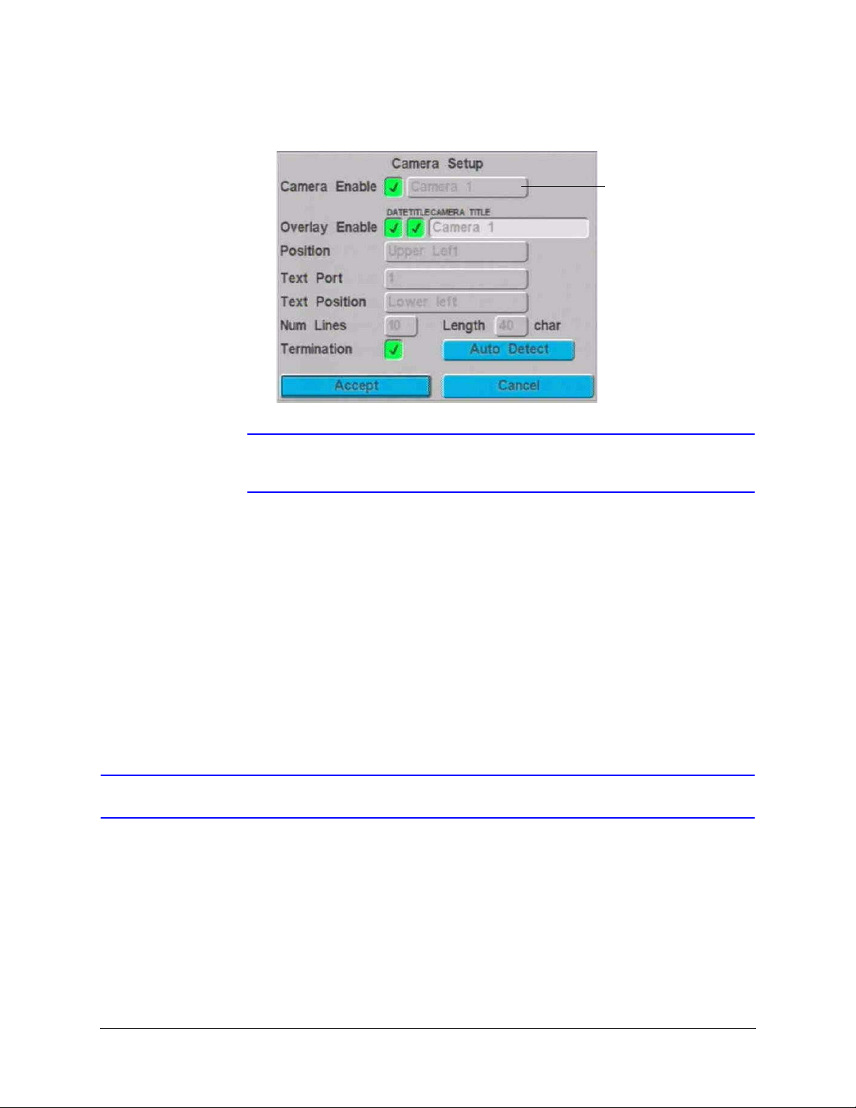
HRDV Reference Guide
4. Enable cameras (MENU ➤ System Setup ➤ Video Inputs).
Select camera to
view/configure
Each connected camera
must be enabled
Note Ensure that any cameras not being used are disabled to prevent alarms from
occurring.
5. Verify timelapse recording is occurring:
a. Exit Program mode.
b. Look for a dull red dot on the top right-hand corner of Monitor 1. This indicates
that timelapse recording is taking place.
6. View the current clip being recorded:
a. Press PLAY and enter your user name and password when prompted. Press
Enter.
b. Use the jog wheel controls to review the most recent clip.
For more extensive clip reports, see Chapter 17, Report Generation.
Setting Simple Timelapse Mode With Motion Detect Enabled
Motion detect enabled causes the HRDV to only record timelapse clips of the individual
cameras that motion is detected. To set Simple Timelapse with motion detect:
1. Follow the procedure for Simple Timelapse above.
Rev 1.00 65 Document 900.0261
04/05
Page 84
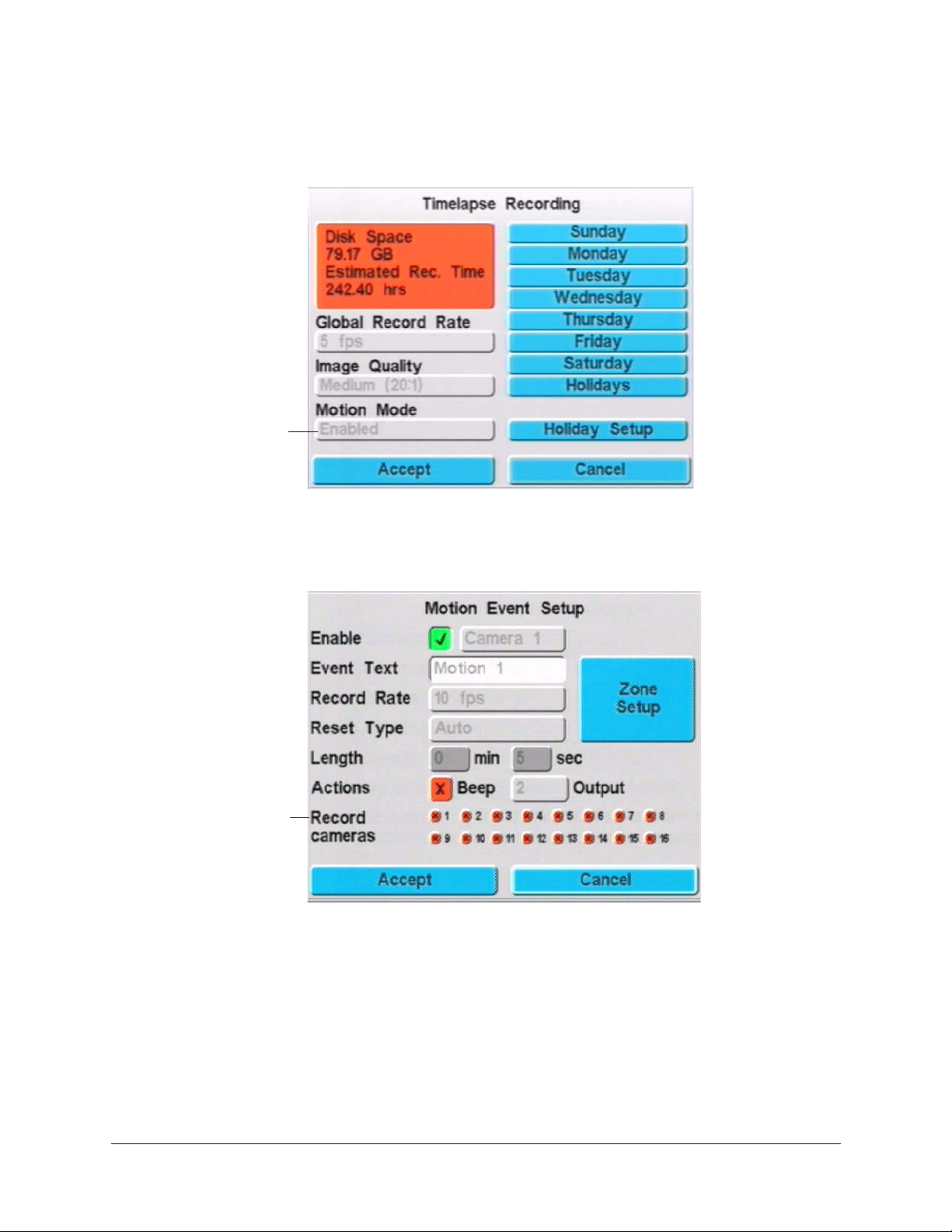
Timelapse Recording Setup
Enable Motion Mode
2. Enable motion detection in the Motion Mode field on the Timelapse recording screen
(MENU
➤ Timelapse Recording). See Figure 12-1.
3. Ensure that the cameras are enabled for motion detection but are not set to record
motion video clips:
a. Go to the Motion Events screen (MENU
➤ Event Recording ➤ Motion
Events).
De-select (X) all cameras
in Record cameras field
or motion video clips will
also be stored in the
event partition
b. Select Camera 1 and enable motion detection. Repeat for each camera
connected to the HRDV.
Rev 1.00 66 Document 900.0261
04/05
Page 85
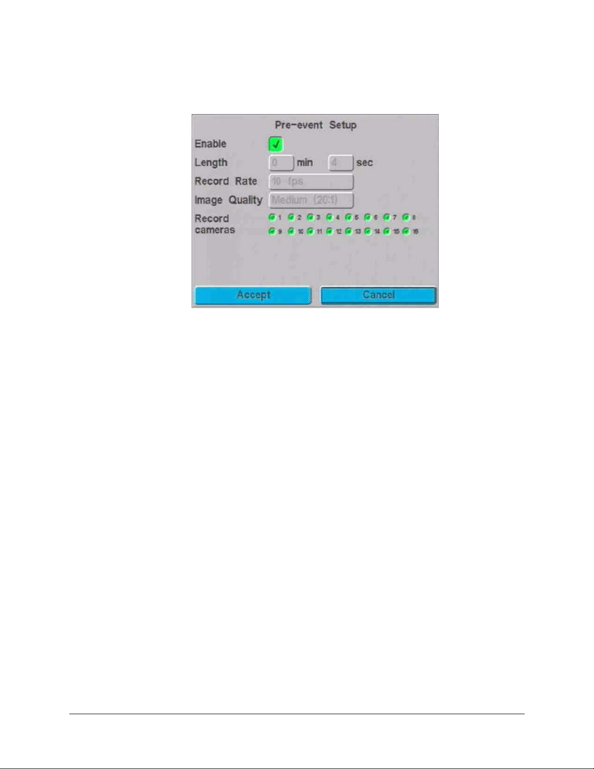
HRDV Reference Guide
4. Ensure pre-event setup is disabled (MENU ➤ Event Recording ➤ Pre-event
Setup).
5. Exit Program mode.
6. Look for a dull red dot on the top right-hand corner of Monitor 1. This indicates that
timelapse recording is taking place and that motion is currently detected.
If you see a dull red dot with a slash, this indicates that camera(s) are ready to record
and are waiting for motion to be detected.
To set up motion sensitivity, see Chapter 13.
Rev 1.00 67 Document 900.0261
04/05
Page 86
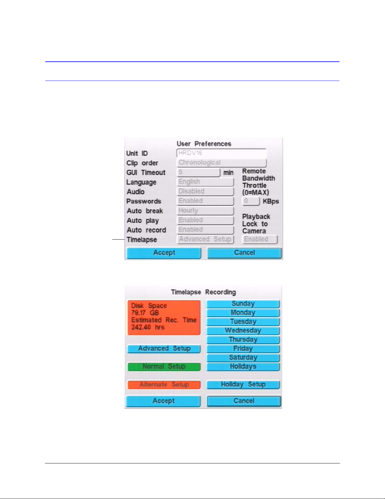
Timelapse Recording Setup
Setting Advanced Timelapse Mode
The Advanced Timelapse mode enables you to program both normal (day) and alternate
(night) recording schedules.
1. On the User Preferences screen (MENU ➤ System Setup ➤ User Preferences), set
the Timelapse field to Advanced Setup. Select Accept to confirm the setting and exit
the screen.
Set to Advanced Setup
2. From the Main Menu, select Timelapse Recording to display the Timelapse
Legend
Advanced Setup. Sets
Advanced schedule camera
record rates, image quality, and
motion mode
Normal Setup. Sets Normal
schedule camera record rates,
image quality, and motion mode
Alternate Setup. Sets Alternate
schedule camera record rates,
image quality, and motion mode
3. Select Advanced Setup to display the Advanced Setup screen.
Recording screen.
Rev 1.00 68 Document 900.0261
04/05
Page 87
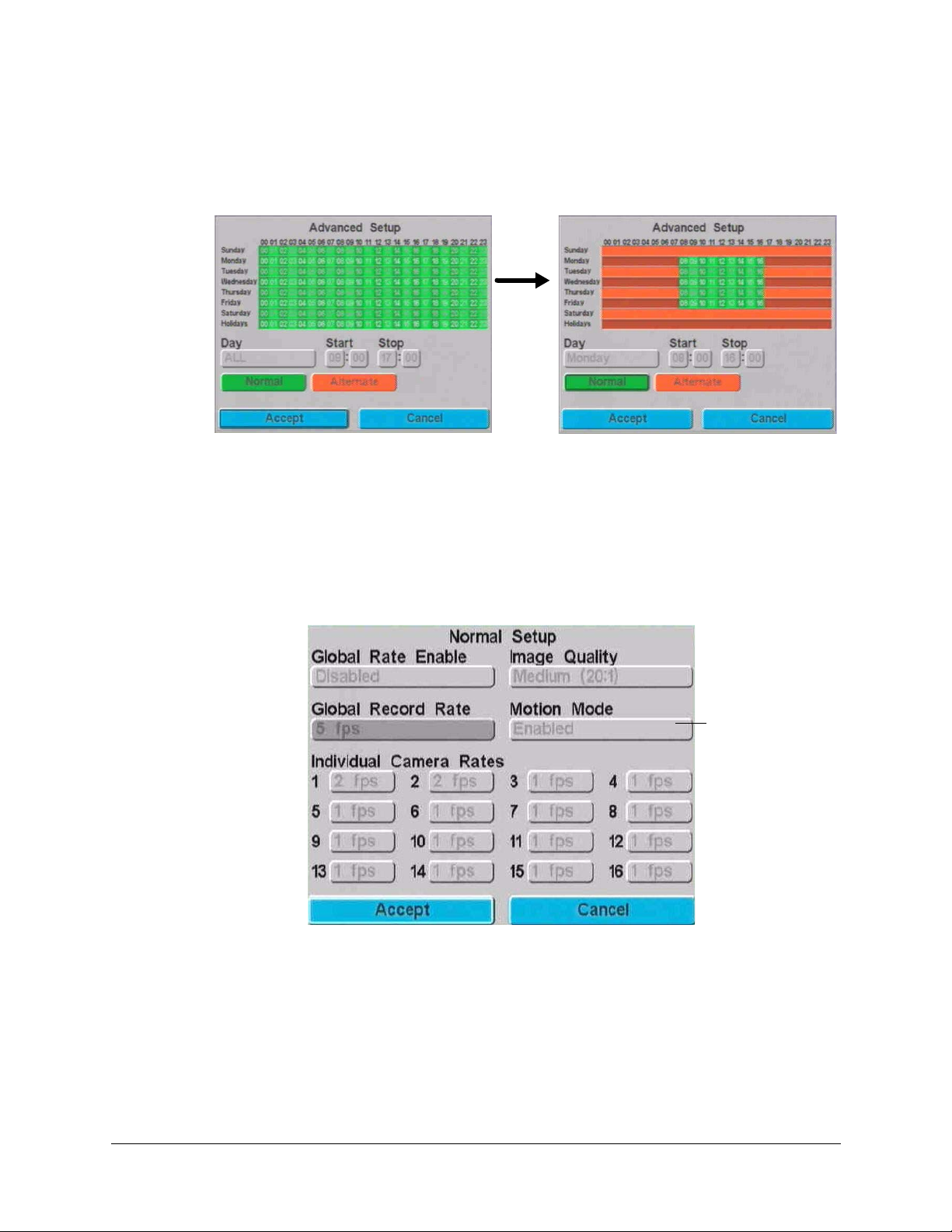
HRDV Reference Guide
Figure 12-3 Typical Advanced Recording Schedule Setup
Monday to Friday, 8:00 a.m. to 5:00 p.m.
Closed after 5:00 p.m., weekends, and holidays
You assign normal and alternate weekly and hourly schedules here.
a. Enter start and stop times to assign normal and alternate schedule times.
When entered, the display changes to show your settings. Green indicates the
normal schedule and red indicates the alternate schedule.
b. When you are satisfied with your settings, select Accept to confirm the settings
and return to the Timelapse Recording screen.
4. Set the normal recording rates. On the Timelapse Recording screen, select Normal
Setup to display the Normal Setup screen.
Enable Motion Mode
if you want the system
to detect motion in
Timelapse mode
In the Normal Setup mode, you can program the HRDV16/8 to use a global record rate or
set a record rate for each camera. The global rate is common for timelapse VCR type
recording. Typically, 24 hour timelapse mode is equivalent to 5 fps and High Density
(real-time) timelapse recording is about 15 fps.
Disabling global record rate allows you to set the rate (fps) for each camera, in essence
allowing you to prioritize certain cameras to have more recorded images than others.
Rev 1.00 69 Document 900.0261
04/05
Page 88
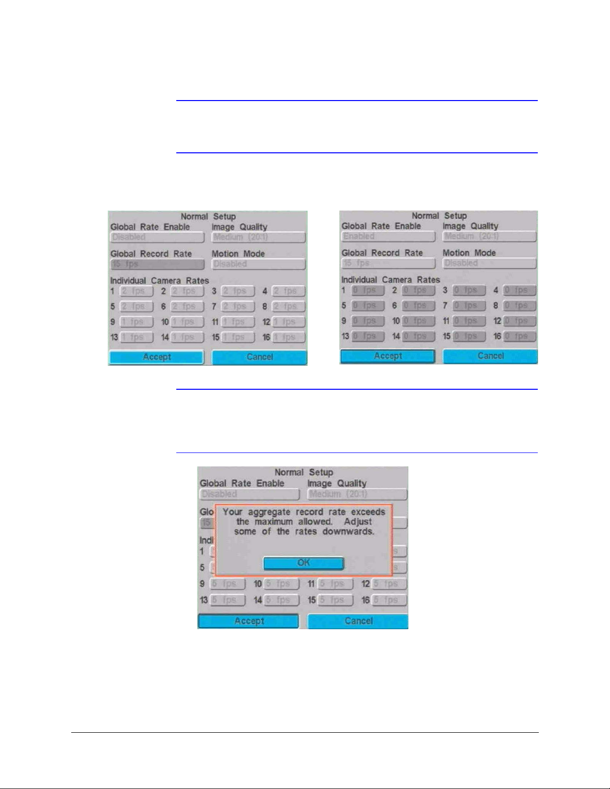
Timelapse Recording Setup
Note Only those cameras in the record sequence are available for RAS to view in
live mode. For example, if you only enable cameras 1-12 in the record
sequence, RAS cannot view live cameras 13-16.
Figure 12-4 Timelapse Global Rate Examples
Program 2 fps for cameras 1-8 and 1 fps for cameras 9-16
Note If you exceed the total number of (fps) fields per second (60 NTSC, 50 PAL for
the HRDV16, 30 NTSC, 25 PAL for the HRDV8), you see a warning message
when you select Accept. If this happens, reduce the individual record rates so
the accumulated total is 60/50 fps or less.
Set a global record rate of 15 fps for all enabled cameras
a. Enter desired values based on the following field descriptions.
Rev 1.00 70 Document 900.0261
04/05
Page 89
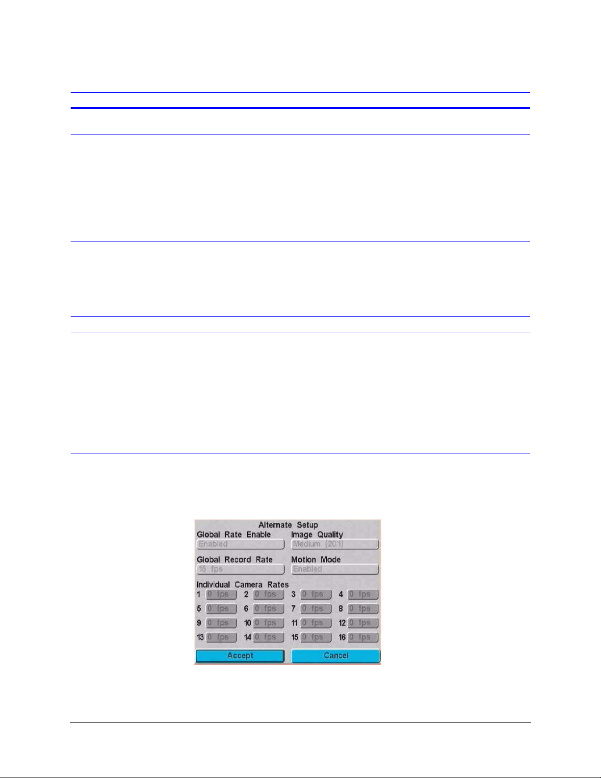
HRDV Reference Guide
Field Description
Global Rate Enable Enables (default) or disables the global rate option. The changes you can make on
the screen are depend on whether this field is enabled or disabled.
Image Quality Set the global compression setting. The higher the quality, the slower the
transmission of images and the faster your storage disk fills. Options are:
High (10:1 or 15:1)
Medium (20:1 or 25:1) — The default
Low (30:1, 35:1, 40:1)
Very Low (45:1, 50:1)
Note The size of a single, high quality (10:1 compression), full frame color video
image is approximately 35 KB for NTSC.
Global Record Rate Set the global record rate, in fields per second, that should be recorded by all
cameras. Options are:
0, .1, .2, .5, 1 to 16 (10 is default), 20 to 60 in increments of five.
Note When two or more cameras are set to Motion, the record rate is split between
them.
Motion Mode When enabled, the system detects motion in Timelapse mode.
Individual Camera Rates Set the record rate for each camera. The total number of fields that can be recorded
each second by all 16 cameras cannot add up to more than 60 fields per second for
NTSC (50 fps for PAL).
For the HRDV8, the total fps that can be recorded by all 8 cameras cannot add up
to more than 30 fps for NTSC (25 fps for PAL).
Options are:
0, .25, .5, 1 to 9 in increments of one, 10 to 30 in increments of five. (5 is default)
The lower the record rate, the longer you can record video before your storage disk
is full.
b. When you are satisfied with your settings, select Accept to confirm the settings
and return to the Timelapse Recording screen.
5. Set the alternate recording rates. On the Timelapse Recording screen, select
Alternate Setup to display the Alternate Setup screen.
a. Enter desired values. The fields are the same as on the Normal Setup screen (see
page 71).
Rev 1.00 71 Document 900.0261
04/05
Page 90

Timelapse Recording Setup
b. When you are satisfied with your settings, select Accept to confirm the settings
and return to the Timelapse Recording screen.
6. Enable cameras for each day of the week and holidays as required by your system.
The procedure is the same as for setting Simple Timelapse Mode (see Setting Simple
Timelapse Mode With Motion Detect Enabled, page 65).
Legend
Set. Sets record times for the entire day.
Clear. Clears all time settings on the current screen.
Copy. Copies time settings to all the other days of the week.
In this example, all cameras record Monday to Friday, 24 hours each day. During the
alternate (red) times, you may still want to record all cameras, but at a different
recording rate/quality, or you could disable some cameras from recording during
certain periods of time. For example, do not record cameras 13 to 16 after-hours (from
5:00 p.m. to 8:00 a.m.).
7. Ensure that the cameras are enabled.
Go to the Camera Setup screen (MENU
➤ System Setup ➤ Video Inputs).
8. If you are using motion detection enabled, ensure that motion event detection is
enabled for all cameras as required.
Rev 1.00 72 Document 900.0261
04/05
Page 91
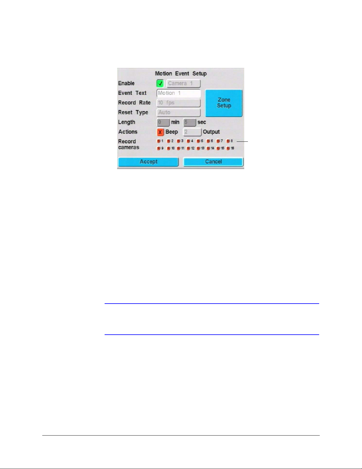
HRDV Reference Guide
a. Go to the Motion Event Setup screen (MENU ➤ Event Recording ➤ Motion
Events).
De-select (X) all cameras in
Record cameras field or motion
video clips will also be stored in
the event partition
b. Select Camera 1 and ensure that Enable is checked. Repeat for all cameras
connected to the HRDV.
c. Select Accept to confirm your settings and exit this screen.
9. Exit the configuration screens.
Motion Mode in Advanced Mode
Motion mode is also available in the Advanced mode. Motion mode uses the Motion Event
Setup to record timelapse video only when there is motion in the defined camera(s) field of
view that meets the motion detection criteria for size, sensitivity, and direction.
This feature is typically used to record motion during the evening and on weekends and
record this information in the timelapse section of the disk instead of in the event section.
This frees up hard drive space in the event partition that can be used to supplement text
event storage.
Note To ensure that you do not duplicate motion detection images in both the
timelapse clip and also in a Motion Event clip, disable ALL cameras at the
bottom of the Motion Event Setup Screen for each camera being defined.
Rev 1.00 73 Document 900.0261
04/05
Page 92
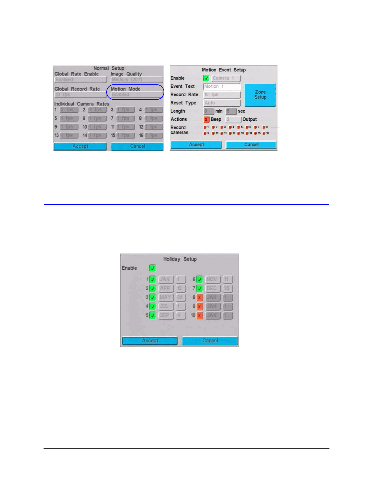
Timelapse Recording Setup
Figure 12-5 Timelapse with Motion Mode in Advanced Mode
Setting Recording Times For Holidays
Turn on/off all
cameras to record
Motion clips (event
partition)
You can set user-defined holidays for up to ten holiday dates. To set holidays:
1. Access the Holiday Setup screen (MENU ➤ Timelapse Recording ➤ Holiday
Setup). Figure 12-6 displays.
Figure 12-6 Holiday Setup Screen
2. On the Holiday Setup screen you can set up to ten holidays. When you set this field to
enable, the red X changes to a green and the numbered date settings become
available.
3. To enable a date, move to the X beside that date and press Enter.
4. Move to the month box and press Enter to activate it. Select the desired month using
either the control buttons or the jog wheel, then press Enter. The month display
returns to white with the selected month displayed in the box.
5. Set the date using the method described in step 4.
After you have set the desired holidays, you must specify the Holiday recording times in the
Recording Holidays screen.
Rev 1.00 74 Document 900.0261
04/05
Page 93

HRDV Reference Guide
6. Select Accept to go back to the Timelapse Recording screen.
7. Select Holidays to go to the Recording Holidays screen (similar to Figure 12-2).
8. Set the holiday record times following the procedure in Setting Simple Timelapse
Mode With Motion Detect Enabled on page 65.
9. Select Accept to go back to the Timelapse Recording screen. Select Accept again to
save your changes and exit to the Main Menu.
Note The holiday time settings apply to all selected holidays. Times cannot be set
independently for each holiday.
Rev 1.00 75 Document 900.0261
04/05
Page 94

Timelapse Recording Setup
Rev 1.00 76 Document 900.0261
04/05
Page 95

Motion Event Recording Setup
This chapter describes how you set the system to respond to external events.
Note Event video clips are stored in the event disk partition.
When you set both timelapse and event recording simultaneously, the event recording
settings are used when an event is detected. For example, if a motion event is detected
on Camera 4, the settings you entered into the Motion Event function for Camera 4 are
used.
In timed mode, the event is recorded for a specific time.
In automatic mode, the recording continues as long as the event is active.
Events have a record speed and quality independent of the timelapse setting. During
events, you may specify whether the beeper should go off or if any of the alarm outputs
change state. You can also select which cameras are recorded during the event.
13
Setting Motion Events
Before you use motion events, you must enable them for each camera and enter some
basic settings. For more information on how a motion event triggers an event video clip
to be recorded, see Event Handling on page 58.
Access the Motion Event Setup screen as follows: MENU
Events. Figure 13-1 displays.
Rev 1.00 77 Document 900.0261
➤ Event Recording ➤ Motion
04/05
Page 96
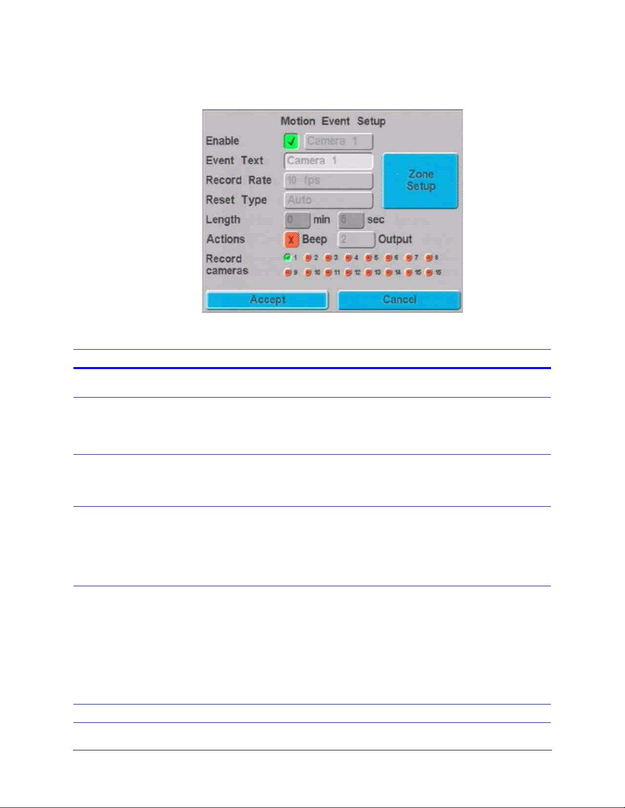
Motion Event Recording Setup
The following table describes the fields on the Motion Event Setup screen.
Figure 13-1 Motion Event Setup Screen
Important Note
All cameras selected
in the Record
cameras field will
store video in the
event partition.
Field Description
Enable Enables (default) or disables the motion event option. To make changes on the
screen, this field must be enabled.
Camera 1 Options are:
Camera 1 (default) to Camera 16. We recommend that you leave this field at the
default setting. When you change this field (for example to Camera 3) only camera
3 is enabled in the Record cameras field.
Event Text Changes the text (title) for the enabled camera. This text is used when you create
a report (see Report Generation on page 113) or review events (see Playing Video
Clips in a Report on page 121). To change the text, use the control buttons or jog
wheel.
Record Rate Specify the record rate, in fields per second, that should be recorded by each
camera. Options are:
.1, .2, .5, 1 to 16 (10 is default), 20 to 60 in increments of five.
Note When two or more cameras are set to Motion, the record rate is split
between them.
Reset Type Events can be reset using one of two reset types:
Auto. Recommended setting. When motion has stopped being detected the
software will begin a countdown for a user selectable length of time before ending
the clip. If motion is detected again during this time, the software will reset the
counter and begin the countdown again once motion is not detected. The purpose
of this is to merge together what would otherwise be several very short motion
clips.
Timed. Motion event stops recording and re-arms after the time specified in the
Length field.
Length Value from 1 second to 9 minutes 59 seconds.
Rev 1.00 78 Document 900.0261
04/05
Page 97
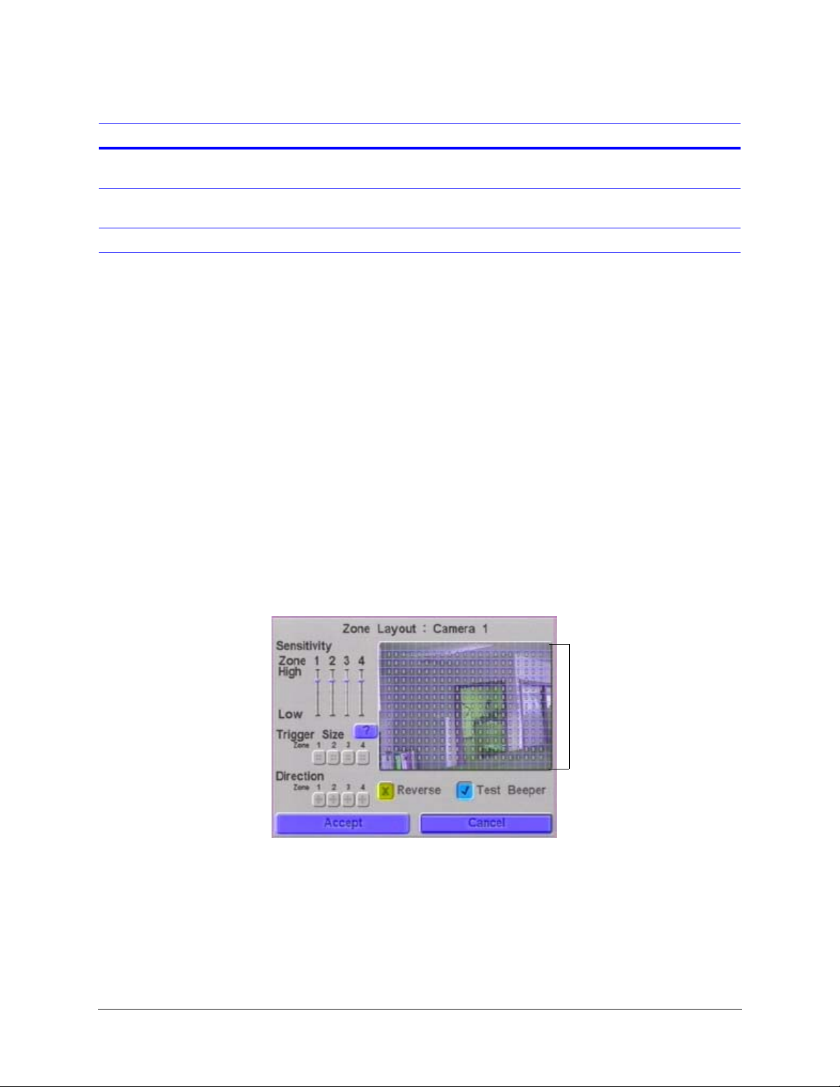
HRDV Reference Guide
Field (Cont’d) Description
Actions Choose whether or not the HRDV16/8 should beep or trigger the Alarm Output
contact (to activate an external light, bell, and so on).
Record cameras Define which cameras (16 cameras for HRDV16, 8 cameras for HRDV8) will record
motion event video clips. These are stored in the event disk drive partition.
Zone Setup See Setting Up Motion Zones.
Setting Up Motion Zones
Use the Motion Zones screen to:
• Assign screen areas for up to four independent motion zones per camera
• Set individual sensitivities
• Set size of target (trigger size)
Testing the effectiveness of the motion triggers is key for optimal disk utilization.
When you use the motion detection function, a reference image is saved to provide a
background picture for motion detection. This reference image automatically updates at
regular intervals so that, for example, gradually changing light conditions will not trigger a
motion detection alarm. This reference update process is automated for optimal system
performance.
Access the Motion Zones screen as follows: MENU
Events
➤ Zone Setup. Figure 13-2 displays.
Figure 13-2 Zone Layout Screen per Camera
➤ Event Recording ➤ Motion
Motion Detection screen
When motion is detected, the
squares turn red.
Rev 1.00 79 Document 900.0261
04/05
Page 98

Motion Event Recording Setup
The following table describes the fields on the Zone Layout screen.
Field Description
Sensitivity Zone Assign each zone its own sensitivity using the sliders.
Trigger Size Set the target size for each zone and each camera. The trigger size buttons show
the number and arrangement of zone squares that must be active to trigger a
motion alarm.
Direction Assign a motion direction for each zone.
Test Beeper Enable (default) or disable the test beeper. Enabling the test beeper causes it to
beep when motion is detected.
Reverse Enabling the Reverse function causes the system to beep for the selected zones
whenever motion is not detected.
Caution Set up motion detection with consideration and care to prevent unnecessary
alarms. Moving shadows, sunlight through windows, the moving second hand
of a ticking clock, and so on, can cause unexpected and unwanted alarms if
they are not considered during system setup.
We recommend that you evaluate any motion detection setup for an extended
period of time (24 to 48 hours) to fine tune settings and to verify desired
operation.
The on-board motion detection is well suited to indoor applications.
Outdoor applications are susceptible to the vagaries of nature,
making it more difficult to anticipate all situations. Prior to final
outdoor use, extensive testing under a variety of conditions is
recommended.
The motion detection function is responsive—accurate and quick to detect motion.
However, the more cameras that use motion detection at the same time, the slower the
detection processing speed. If multiple cameras use motion detection simultaneously, we
recommend that you individually review the motion detection for each camera during
various activity periods. This helps you verify that motion detection is performing at the
desired response level.
The Zone screen divides the screen into small squares. To set up zones for all four zones:
1. Move the cursor to highlight the motion detection screen, then press Enter.
2. Use the front panel buttons to move to the first square you want to assign to zone 1.
Use Camera button 1 to assign the square you are on to zone 1.
3. Move to any additional squares you want to assign to zone 1, then press Camera
button 1. You will see zone 1 represented by the squares with the number 1.
4. To remove a square from zone 1, move to that square and press Camera button 1
again to remove the number 1.
5. Press Enter when you complete motion zone area 1.
6. Repeat step 1 to step 5 to assign zones 2, 3, and 4.
Rev 1.00 80 Document 900.0261
04/05
Page 99
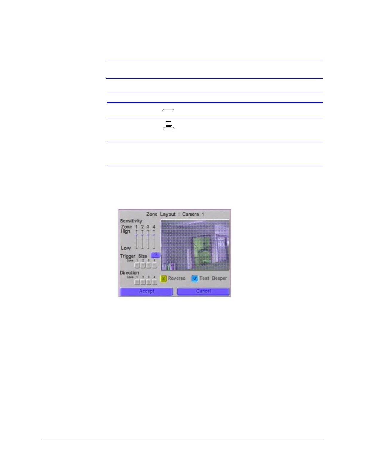
HRDV Reference Guide
Note Each zone may have as many or as few squares included as you want.
Press button … To perform this action
Camera 5 Erases programmed zones
5
Camera 16 Performs full screen operation of the previously
16
activated button. For example, Camera 5 button
followed by Camera 16 button blanks the grid.
Press and hold a Camera
Fills the whole screen with the same zone assignment.
button (1 to 4) AND press
Camera 16 button.
Note that the zone numbers turn red and a beep sounds when motion is detected as
defined by your Direction and Trigger Size field settings. This helps you make the
correct settings when you set up your zones. You may toggle on/off the beep while
setting up the zones by pressing PLAY on the front panel of the HRDV16/8.
7. Select Accept to activate your changes and exit this screen.
8. Repeat for all cameras as required.
Rev 1.00 81 Document 900.0261
04/05
Page 100
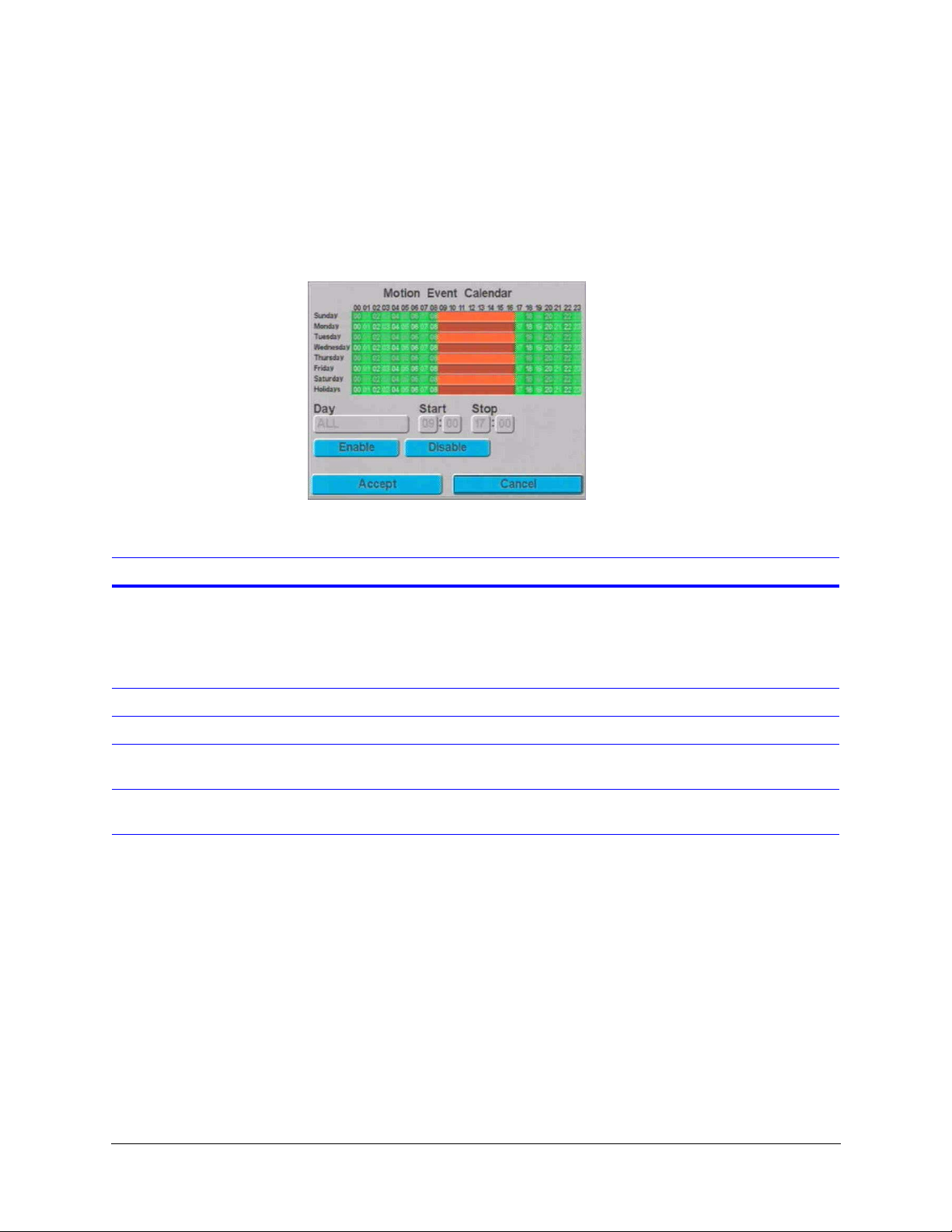
Motion Event Recording Setup
Setting Motion Event Recording Calendar
Use this screen (MENU ➤ Event Recording ➤ Motion Event Calendar) to specify when
event recording is active—similar to the timelapse recording (see Setting Simple Timelapse
Mode With Motion Detect Enabled on page 65). Figure 13-3 displays.
Figure 13-3 Motion Event Calendar Screen
Green areas indicate enabled recording
times Red areas indicate disabled
recording times.
The following table describes the fields on the Event Calendar screens.
Field Description
Day Options are:
Sunday to Saturday. Program each day individually
ALL. Program all the days of the week the same
Holidays. Program holiday scheduling
Start Enter the time you want motion event recording to begin.
Stop Enter the time you want motion event recording to end.
Enable After you have set up the start and stop times for the desired days, select Enable,
then Accept to confirm your settings.
Disable Select Disable, then Accept to deactivate motion event recording for the days and
times set.
Rev 1.00 82 Document 900.0261
04/05
 Loading...