

Page 1

Day/Night DNS Fixed
Dome Camera
NTSC / PAL
HD4D HD4DX
User Guide
Document 800-00023 – Rev D – 05/07
Page 2

Revisions
Issue Date Revisions
A 04/07 New document.
B 05/07 Increase line weight of illustrations.
C 05/07 Corrected specifications.
D 06/07 Changes:
Page 14, LL switch is on power supply board.
Page 18, corrected Day/Night mode explanation.
Page 24, corrected Vertical Phase Adjustment to 0 - 359°.
2
Page 3
Warnings
Installation and servicing should be performed only by qualified and experienced technicians
to conform to all local codes and to maintain your warranty.
WARNING! 12 VDC/24 VAC models require the use of CSA Certified/UL Listed
Class 2 power adapters to ensure compliance with electrical safety
standards.
WEEE (Waste Electrical and Electronic Equipment). Correct disposal of
this product (applicable in the European Union and other European
countries with separate collection systems). This product should be
disposed of, at the end of its useful life, as per applicable local laws,
regulations, and procedures.
Explanation of Graphical Symbols
CAUTION
RISK OF
ELECTRIC SHOCK
DO NOT OPEN
CAUTION: TO REDUCE THE RISK OF
ELECTRIC SHOCK, DO NOT REMOVE
THE COVER. NO USER-SERVICEABLE
PARTS INSIDE REFER SERVICING TO
QUALIFIED SERVICE PERSONNEL
Document 800-00023 Rev D 3
05/07
THIS SYMBOL INDICATES
THAT DANGEROUS VOLTAGE
CONSTITUTING A RISK OF
ELECTRIC SHOCK IS PRESENT
WITHIN THE UNIT.
THIS SYMBOL INDICATES
THAT IMPORTANT OPERATING
AND MAINTENANCE
INSTRUCTIONS ACCOMPANY
THIS UNIT.
Page 4

FCC Compliance Statement
Information to the User: This equipment has been tested and found to comply with the limits
for a Class A digital device. Pursuant to Part 15 of the FCC Rules, these limits are designed to
provide reasonable protection against harmful interference when the equipment is operated in
a commercial environment. This equipment generates, uses, and can radiate radio frequency
energy and, if not installed and used in accordance with the instruction manual, may cause
harmful interference to radio communications. Operation of this equipment in a residential area
is likely to cause harmful interference in which case the user will be required to correct the
interference at his own expense.
Caution Changes or modifications not expressly approved by the party
responsible for compliance could void the user’s authority to operate the
equipment.
This Class A digital apparatus complies with Canadian ICES-003.
Manufacturer’s Declaration of Conformance
The manufacturer declares that the equipment supplied with this guide is compliant with the
essential protection requirements of the EMC directive 89/336/EEC and the Low Voltage
Directive LVD 73/23 EEC, conforming to the requirements of standards EN 55013 for
emissions, EN 50130-4 for immunity, and EN 60065 for Electrical Equipment safety.
4
Page 5

Contents
Introduction . . . . . . . . . . . . . . . . . . . . . . . . . . . . . . . . . . . . . . . . . . . .6
Before You Begin . . . . . . . . . . . . . . . . . . . . . . . . . . . . . . . . . . . . . .6
Unpack Everything. . . . . . . . . . . . . . . . . . . . . . . . . . . . . . . . . . .6
Equipment Required . . . . . . . . . . . . . . . . . . . . . . . . . . . . . . . . .6
Installation . . . . . . . . . . . . . . . . . . . . . . . . . . . . . . . . . . . . . . . . . . . . . 7
Mounting the Camera . . . . . . . . . . . . . . . . . . . . . . . . . . . . . . . . . .8
Connecting Cables Through the Housing Base . . . . . . . . . . . .8
Connecting Cables Through the Side Conduit . . . . . . . . . . . . .9
Electrical Box Installations . . . . . . . . . . . . . . . . . . . . . . . . . . . 10
Connecting the Wiring . . . . . . . . . . . . . . . . . . . . . . . . . . . . . . . . 12
Adjusting the Camera . . . . . . . . . . . . . . . . . . . . . . . . . . . . . . . . . 13
Line Lock . . . . . . . . . . . . . . . . . . . . . . . . . . . . . . . . . . . . . . . . 14
Adjusting the Lens Focus . . . . . . . . . . . . . . . . . . . . . . . . . . . 14
Camera Settings . . . . . . . . . . . . . . . . . . . . . . . . . . . . . . . . . . . . . . .15
Camera Functions . . . . . . . . . . . . . . . . . . . . . . . . . . . . . . . . . . . .15
OSD Menu Structure . . . . . . . . . . . . . . . . . . . . . . . . . . . . . . . . . 16
SETUP Menu . . . . . . . . . . . . . . . . . . . . . . . . . . . . . . . . . . . . . . . 17
SPECIAL Menu . . . . . . . . . . . . . . . . . . . . . . . . . . . . . . . . . . . . . .18
Adding a Camera Title Display . . . . . . . . . . . . . . . . . . . . . . . 19
Sync Control Setup . . . . . . . . . . . . . . . . . . . . . . . . . . . . . . . . 19
Motion Detection Setup . . . . . . . . . . . . . . . . . . . . . . . . . . . . .20
Privacy Mode Setup. . . . . . . . . . . . . . . . . . . . . . . . . . . . . . . . 20
Installing the Enclosure Cover . . . . . . . . . . . . . . . . . . . . . . . . . . 21
Routine Maintenance . . . . . . . . . . . . . . . . . . . . . . . . . . . . . . . . . . 21
Solving Common Technical Issues . . . . . . . . . . . . . . . . . . . . . . . . 22
Warranty and Service . . . . . . . . . . . . . . . . . . . . . . . . . . . . . . . . . . . 23
Specifications . . . . . . . . . . . . . . . . . . . . . . . . . . . . . . . . . . . . . . . . .24
Cable Guidelines . . . . . . . . . . . . . . . . . . . . . . . . . . . . . . . . . . . . . . 26
Document 800-00023 Rev D 5
05/07
Page 6

Introduction
The unobtrusive, low-profile design of the HD4D CCTV Camera is ideal for indoor and outdoor
installations in commercial and residential venues.
Before You Begin
Please read this guide carefully before you install the HD4D CCTV Camera.
Keep this guide for future reference.
Unpack Everything
Check that the items received match those listed on the order form and packing slip. The
HD4D packing box should include, in addition to this User Guide:
• One fully-assembled HD4D camera, including factory-installed pigtail power and video
connections
• One HD4D hardware kit
• One bag containing mounting screws
• One Product warranty
If any parts are missing or damaged, contact the dealer you purchased the camera from or call
Honeywell Customer Service (see Warranty and Service).
Equipment Required
You will require the following tools to complete the installation:
• Phillips screwdriver
• Tools supplied in the hardware kit (three Allen keys): one for the security screw on the lid
one for the conduit plug locking screw, and one for the lens locking screw
•Side-cutters
6
Page 7
Installation
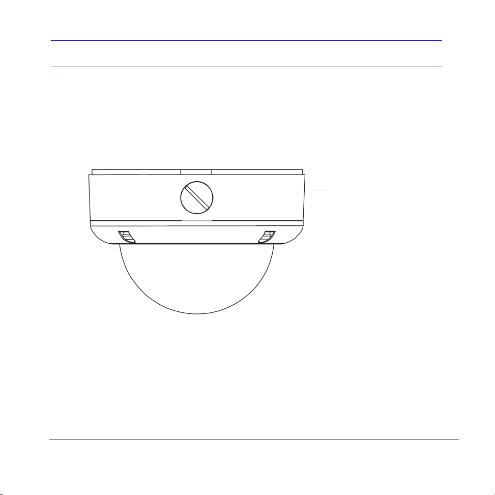
The HD4D is weather-sealed for indoor or outdoor locations. The HD4D is a fully-integrated
enclosure with camera and lens. The wiring can be completely concealed to reduce the risk of
tampering.
Figure 1 Installation Components
HD4D dome
enclosure
Document 800-00023 Rev D 7
05/07
Page 8
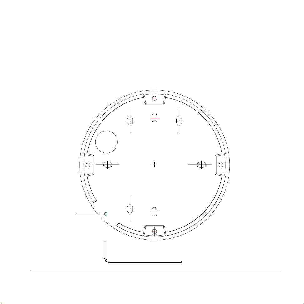
Mounting the Camera
The HD4D Camera is designed to be surface mounted on a wall or ceiling. Before you
mount the camera, use the mounting template provided to mark and pre-drill the holes.
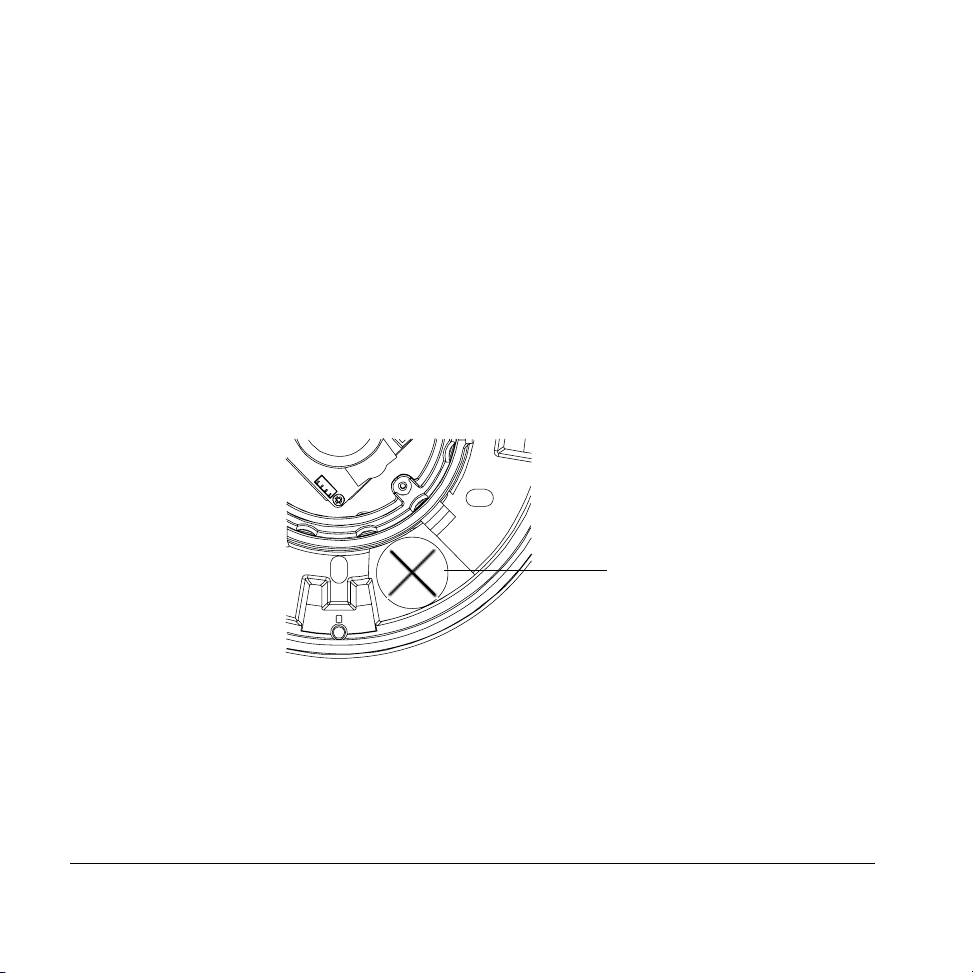
Connecting Cables Through the Housing Base
For installations requiring pulling cables through the grommet located in the bottom of the
base:
1. Use a sharp knife to cut an ! opening in the base gasket (see the figure below). Be
careful. The opening should only be big enough to feed the cable assembly through.
2. Pull the cabling through the opening.
3. Apply appropriate sealant around the opening to prevent moisture from entering the
housing.
Base gasket opening
!
8
Page 9
Connecting Cables Through the Side Conduit
1. Peel back the bottom flat gasket below the side conduit just enough to expose the security
screw.
2. Use the Allen key supplied to loosen and remove the security screw (see below).
3. Use a flat screwdriver to unscrew the conduit plug.
4. Pull the cabling through the hole.
5. Apply appropriate sealant around the opening to prevent moisture from entering the
housing.
security screw
supplied
allen key
Document 800-00023 Rev D 9
05/07
Page 10

Electrical Box Installations
Figure 2 illustrates how to mount the HD4D directly to a 4S electrical box or directly to wall
or ceiling. For 4S electrical box installations, the optional adapter plate can be used to
cover ceiling or wall imperfections around the electrical box opening.
Figure 2 4S Electrical Box Installation
Electrical box
(not supplied)
Ceiling/wall
Secure the optional
adapter plate to the
4S electrical box
using appropriate
screws (not supplied)
Secure the HD4D base with
screws appropriate to your
installation (supplied)
For surface mount
installations (without an
electrical box), use
#6-1 7/16 inch slotted Type
A screws (x4) supplied
Adapter plate
(use is optional)
HD4D base
Note Honeywell recommends that you orient the conduit plug facing downwards
(wall mount installations) to prevent moisture from entering the housing.
10
Page 11

Figure 3 illustrates how to mount the HD4D directly to a double gang or single gang
electrical box.
Figure 3 Double Gang/Single Gang Electrical Box Installation (Single Gang Shown)
Electrical box
(not supplied)
Ceiling/wall
Secure the HD4D base with
screws appropriate to your
installation (not supplied)
For surface mount
installations (without an
electrical box), use
#6-1 7/16 inch slotted Type
A screws (x4) supplied
Document 800-00023 Rev D 11
05/07
HD4D base
Page 12

Connecting the Wiring
Follow Figure 4 for the wiring connection.
Figure 4 Wiring Connection
Video: female BNC
(yellow)
Note For secure installations, surface
mounted cables should be
protected by plastic or metal
cable covers.
12
Power: 12 VDC
or 24 VAC
+ Red
- Black
Page 13

Adjusting the Camera
To adjust the HD4D Camera:
1. Apply 12 VDC or 24 VAC power to the camera and monitor the video signal.
2. Loosen the screws that lock the gimbal assembly in place (see Figure 5).
3. Adjust the camera carrier to the desired view.
4. Tighten the screws to lock the gimbal assembly in place.
Note Orient the camera as shown in Figure 5 to maintain the correct picture
orientation.
Figure 5 Gimbal Adjustment
Angle viewTop view
Locking screw. Loosen to
adjust Horizontal (B).
Locking screw
C
Set focal length
(bottom)
Document 800-00023 Rev D 13
05/07
Line Lock switch
must be left in
ON position.
Set focus
(top)
A
Setscrews (x2). Loosen to
adjust Pan (C). Other
setscrew located on
opposite side.
B
Legend
A = Tilt rotation
B = Horizontal rotation
C = Pan rotation
Page 14

Line Lock
The Line Lock switch on the power supply board must be left in the ON position. To switch
between Line Lock and Internal Lock, use the OSD menu (see Sync Control Setup, page 19
).
Adjusting the Lens Focus
Lenses are pre-focused at the factory but may require a final adjustment after installation in the
unlikely event the optical effect of the dome causes a slight defocusing of the lens.
TECH TIP! To check the focus, hold the dome over the lens while making any adjustments.
To adjust the camera direction, view angle and focus, connect the service monitor cable
(supplied) to the video monitor output.
14
Page 15

Camera Settings
Camera Functions
Figure 6 Camera Controller
2
Legend
#Description
Video-test monitor output connector
1
Camera OSD control (four position plus center push)
2
L
F
D
N
Document 800-00023 Rev D 15
05/07
R
T
1
Press this control To do this
UP, DOWN Select a new item
LEFT, RIGHT Select a menu item
SETUP (MENU)
(CENTER PUSH)
Enter SETUP MENU,
access a submenu
Page 16

OSD Menu Structure
The HD4D camera menu system consists of one main setup menu for easy programming.
Main MENU Sub-Menus Options
SETUP MENU
1
SHUTTER
2
WHITE BAL.
3
4
5
6
7
SPECIAL
8
LENS
BACKLIGHT
AGC
DNR
SENS-UP
EXIT MENU
DC↵
VIDEO
MANUAL
FLK (FLICKERLESS)
ESC↵
MANUAL↵
ATW
MANUAL↵
AWC↵
OFF
LOW
MIDDLE
HIGH
OFF
LOW↵
MIDDLE↵
HIGH↵
OFF
LOW
MIDDLE
HIGH (with AGC in OFF mode)
OFF
AUTO! (with LENS in MANUAL
mode or SHUTTER in FLX mode)
CAMERA ID
DAY/NIGHT
SYNC
MOTION DET
PRIVACY
MIRROR
SHARPNESS
RESET
16
Page 17

SETUP Menu
Menu Item Option Description
LENS DC!
VIDEO
MANUAL
SHUTTER FLK
MANUAL
ESC!
WHITE BAL
(White Balance)
BACKLIGHT OFF
AGC OFF
DNR (Digital
Noise Reduction)
SENS-UP
(Sensitivity Up)
EXIT Exits the SETUP menu and returns to video monitoring.
ATW
MANUAL
AWC!
LOW
MIDDLE
HIGH
LOW
!
MIDDLE!
HIGH!
OFF
LOW
MIDDLE
HIGH
OFF
AUTO
Selects Lens type. Only DC mode is supported at this time.
Caution Selecting VIDEO or MANUAL adversely affects camera operation.
Adjusts shutter settings.
!
FLK (Flickerless) reduces on-screen flickering.
MANUAL adjusts the shutter speed from 1/60-1/120,000 of a second (NTSC)
or 1/50-120,000 of a second (PAL). Not available in DC lens mode.
ESC (Electronic Shutter Control) adjusts the brightness level on screen. Not
available in DC lens mode.
Controls color on the screen.
!
Select ATW (Auto Tracing White Balance) when the color temp is 2400°K 12000°K; for example, under a fluorescent light, or outdoors.
MANUAL mode allows you to increase or decrease the red or blue factor on
the screen.
AWC (Auto White Balance Control) automatically adjusts the white balance to
your specific environment.
Provides light level control to overcome severe backlighting conditions.
Adjusts value of AGC (Automatic Gain Control). Increase the GAIN level to
brighten the picture (noise/distortion may develop).
Reduces noise/distortion on the screen. Increasing the DNR level reduces
noise but may introduce video artifacts. DNR is deactivated if AGC is turned
off.
Automatically provides a clear image under low-light conditions. You can
control the maximum low-light magnification from 2x to 128x. Increasing
!
magnification may cause noise/distortion.
Document 800-00023 Rev D 17
05/07
Page 18

SPECIAL Menu
On the main SETUP menu:
1. Press UP or DOWN and then select SPECIAL.
2. Push SETUP (MENU) to access the SPECIAL menu.
Menu Item Option Description
CAMERA ID OFF
1
DAY/NIGHT AUTO
2
SYNC INT
3
MOTION DET OFF
4
PRIVACY OFF
5
MIRROR OFF
6
SHARPNESS ON!
7
RESET Restores all factory default settings.
8
RETURN! Returns to the main SETUP menu.
ON
COLOR
BW
L/L
ON
!
ON
!
ON
OFF
Turns ID display off and on. To add a camera title (name and/or number) to
be displayed on the screen, see Adding a Camera Title Display.
When set to AUTO , the camera automatically switches to Night mode
(B/W) when the light level is low.
When set to COLOR, the camera stays in Day mode (Color).
When set to BW, the camera stays in Night mode (B/W).
Synchronizes the vertical interval sync pulse of your camera with other
equipment to reduce the effect of picture roll on the monitor.
Select L/L (Line Lock) mode to adjust the phase from 0° to 359°.
Detects moving objects on screen and displays MOTION DETECTED along
with the number of movements counted. Allows you to select the area on
screen you want to observe (see Motion Detection Setup).
Allows you to mask up to 4 areas of the screen from video monitoring.
Produces a horizontal mirror image on screen.
Sharpens the image on screen. You can adjust the sharpness level from 0 31 (excessive sharpening may cause picture noise to develop).
18
Page 19

Adding a Camera Title Display
On the SPECIAL menu, select CAMERA ID, then press SETUP (MENU)..
1. Press the menu control UP, DOWN, LEFT, or RIGHT
to select a character, then press (SETUP) MENU to
accept it. The character is saved and the title cursor
at the bottom of the screen moves to the next
position. Use the
# $ symbols to go backward or
forward in the title name/number to make changes.
Select CLR to delete the entire title and start again.
2. Repeat step 1 until your camera title is complete.
A B C D E F G H I J K L M
N O P R Q S T U V W X Y Z
a b c d e f g h i j k l m
n o p q r s t u v w x y z
– . 0 1 2 3 4 5 6 7 8 9
# $ CLR POS END
_ _ _ _ _ _ _ _ _ _ _ _ _ _ _
CAMERA ID
3. Select POS to position the camera title on the
screen. Select the position using the menu control,
then press (SETUP) MENU to confirm the position.
4. Select END when you are finished.
Sync Control Setup
On the SPECIAL menu, select SYNC, then press SETUP (MENU).
Menu Item Description
INTERNAL When line lock is not required.
LINELOCK Adjust the vertical phase (VPH):
VPH: 000 - 359 (factory default is 0).
RETURN Press MENU to return to the SETUP menu.
Document 800-00023 Rev D 19
05/07
<SYNC. CONTROL>
SYNC INT (L/L)
RETURN!
Page 20

Motion Detection Setup
On the SPECIAL menu, select MOTION DET, then press SETUP (MENU).
Menu Item Option Description
AREA SEL AREA 1
AREA 2
AREA 3
AREA 4
AREA
STATE
ON
OFF
TOP
DOWN
Select which of the four motion
detection grids top left, top right,
bottom left, bottom right) you would
like to modify.
Choose whether to activate or
deactivate the selected grid.
Press LEFT or RIGHT control to alter
the dimensions of the selected grid.
MOTION DETECTION
AREA SEL AREA 1
AREA STATE ON
TOP |..|................| 10
DOWN |........|..........| 25
LEFT |...|...............| 20
RIGHT |........|..........| 40
Press SET to Return
LEFT
RIGHT
Privacy Mode Setup
On the SPECIAL menu, select PRIVACY, then press SETUP (MENU).
Menu Item Description
AREA SEL AREA 1
AREA 2
AREA 3
AREA 4
AREA STATE ON
OFF
AREA TONE Press LEFT or RIGHT menu
TOP
DOWN
LEFT
RIGHT
Select which of the four masking
grids (top left, top right, bottom
left, bottom right) you would like to
modify.
Choose whether to activate or
deactivate the selected grid.
control to change the shade of the
masking grids.
Press LEFT or RIGHT menu
control to alter the dimensions of
the selected grid.
AREA SEL AREA 1
AREA STATE ON
AREA TONE |...............|...| 80
TOP |..|................| 10
DOWN |........|..........| 25
LEFT |...|...............| 20
RIGHT |........|..........| 40
Press SET to Return
PRIVACY
20
Page 21

Installing the Enclosure Cover
To install the enclosure cover, use the Allen key (supplied) to secure the HD4D dome
enclosure to the base with four #8-32 security screws.
Figure 7 Enclosure Cover Installation
HD4D dome enclosure
#8-32 security screws (x4)
Routine Maintenance
Use regular liquid cleaners to remove dirt and grime from the HD4VC4HR dome.
Caution Do not use harsh or abrasive cleaners which can scratch the
polycarbonate dome and reduce visibility for the camera.
If the camera view is obstructed by scratches, remove the front plate and rotate to find an
unscratched part of the dome.
Document 800-00023 Rev D 21
05/07
Page 22

Solving Common Technical Issues
No Video
❐
Check that the power supply voltage is within the operating
specifications for your camera model. See Specifications for
details.
❐
Check the video signal connections are correct.
❐
Check for a loose connection.
Fuzzy Video
❐
Check the video ground connections.
❐
Check for ground loops.
Call Honeywell Technical Support for additional assistance (see Warranty and Service).
22
Page 23

Warranty and Service
Subject to the terms and conditions listed on the Product warranty, during the warranty period
Honeywell will repair or replace, at its sole option, free of charge, any defective products
returned prepaid.
In the event you have a problem with any Honeywell product, please call Customer Service at
1.800.796.CCTV for assistance or to request a Return Merchandise Authorization (RMA)
number.
Be sure to have the model number, serial number, and the nature of the problem available for
the technical service representative.
Prior authorization must be obtained for all returns, exchanges, or credits. Items shipped to
Honeywell without a clearly identified Return Merchandise Authorization (RMA) number
may be refused.
Document 800-00023 Rev D 23
05/07
Page 24

Specifications
Video Signal Specifications
Pickup device: 1/3 in. Sony Interline CCD sensor
Synchronization system: 12 VDC: Internal / 24 VAC: (Internal or Line lock)
Vertical phase adjustment: Adjustable, 0° - 359°, OSD control
Horizontal resolution: 540 TV lines
Lens type: 3.3 - 12 mm Vari-focal Auto Iris, IR Corrected F1.5,
DC Drive
Minimum illumination response: 0.3 lux @ F1.5 (Color)
0.03 lux @ F1.5 (B/W) - Sens Up
Signal to noise ratio: Better than 50 dB (AGC Off)
Gain control: Automatic, selectable
Lens iris control: DC Auto Iris type
White balance: Selectable: ATW/AWB
Gamma: 0.45
BLC: Low/Middle/High/Off
DNR: High/Medium/Low
DSS: Off/Auto (selectable limit 2X - 128X)
Privacy Function On/Off (4 Programmable Zones)
Video output: 1 V p-p composite
Video output impedance: 75 Ohms
24
Page 25

Format Specifications NTSC PAL
Color video signal format: Standard Standard
Effective picture elements: 768 (H) x 494 (V) 752 (H) x 582 (V)
Scanning system (2:1 interlace): 525 lines, 60 fields/sec. 625 lines, 50 fields/sec.
Electronic shutter: 1/60 - 1/120,000 second 1/50 - 1/120,000 second
General Specifications
Construction: Die cast (housing) Polycarbonate (dome)
Finish: Gray/off white powder coating
Dimensions (D) x (H): 5.5 in. x 3.6 in.(140.2 mm x 91.5 mm)
Weight: 2.5 lb. (1.1 kg) max
Power supply auto switching: 12 VDC @ 4.8 watts max.
24 VAC, 60 Hz @ 3.8 watts max.
Temperature: Storage: -49°F to +167°F (-45°C to +75°C)
Operating: -13°F to +131°F (-25°C to +55°C)
Relative humidity: 0% to 95% RH non-condensing
Regulatory
Emissions: FCC, CE (EN55013)
Immunity: CE (EN50130-4)
Safety: EU: 73/23/EEC LVD)
Environmental: Meets IP66
Document 800-00023 Rev D 25
05/07
Page 26

Cable Guidelines
Maximum Power Supply Cable Length (feet/meters)
Cameras With AC/DC Power Supplies
Wire gauge
Total load
2.5 W 15 VDC 260/79 415/126 1055/322 1680/512
2.5 W 24 VAC 608/185 980/299 2515/767 3930/1198
3.5 W 15 VDC 180/55 290/88 730/220 1170/352
3.5 W 24 VAC 470/143 760/232 1926/587 3065/934
Note Calculations are based on an unregulated linear power supply, which
Maximum Video Coaxial Cable Length (feet/meters)
Maximum length (feet/meters) 750/229 1500/457 2000/610
* Copper clad steel core, 95% braided shield
Optional
Power supply 24 AWG 22 AWG 18 AWG 16 AWG
would be the worst case. Using a regulated or switching power supply
can increase the cable distance. Honeywell recommends using a CSA
Certified/UL listed Class 2 power adapter to ensure compliance with
electrical safety standards.
Cable type RG-59 RG-6 RG-11
Wire gauge 23 AWG* 18 AWG* 16 AWG*
26
Page 27

HD4D/HD4DX Mounting Template
Document 800-00023 Rev D 27
05/07
Page 28

Honeywell Video Systems (Head Office)
2700 Blankenbaker Pkwy, Suite 150
Louisville, KY 40299, USA
www.honeywellvideo.com
℡ +1.800.796.2288
Honeywell Security Australia Pty Ltd.
Unit 5, Riverside Centre, 24-28 River Road West
Parramatta, NSW 2150, Australia
www.honeywellsecurity.com/au
℡ +61.2.8837.9300
Honeywell Security Asia Pacific
33/F Tower A, City Center, 100 Zun Yi Road
Shanghai 200051, China
www.asia.security.honeywell.com
℡ +86 21.2527.4568
Honeywell Security Asia
Flat A, 16/F, CDW Building, 388 Castle Peak Road
Tsuen Wan, N.T., Hong Kong
www.asia.security.honeywell.com
℡ +852.2405.2323
Honeywell Security France
Parc Gutenberg, 8, Voie La Cardon
91120, Palaiseau, France
www.honeywell.com/security/fr
℡ +33.01.64.53.80.40
Honeywell Security Italia SpA
Via Treviso 2 / 4
31020 San Vendemiano
Treviso, Italy
www.security.honeywell.com/it
℡ +39.04.38.36.51
Honeywell Security España
Mijancas 1. 3
P. Ind. Las Mercedes
28022 Madrid, Spain
www.security/honeywell.com/es
℡ +34.902.667.800
a
Planta
Honeywell Video Systems Northern Europe
Netwerk 121
1446 WV Purmerend, The Netherlands
www.honeywell.com/security/nl
℡ +31.299.410.200
Honeywell Video Systems UK Ltd.
Aston Fields Road, Whitehouse Ind Est
Runcorn, Cheshire, WA7 3DL, UK
www.honeywell.com/security/uk
℡ +44 (0) 1928 756999
Honeywell Security South Africa
Unit 6 Galaxy Park, 17 Galaxy Avenue
Linbro Park, P.O. Box 59904
2100 Kengray, Johannesburg, South Africa
www.honeywell.co.za
℡ +27.11.574.2500
Honeywell Security Deutschland
Johannes-Mauthe-Straße 14
D-72458 Albstadt, Germany
www.honeywell.com/security/de
℡ +49.74 31.8 01.0
Honeywell Security Poland
Chmielewskiego 22a, 70-028
Szczecin, Polska
www.ultrak.pl
℡ +48.91.485.40.60
Honeywell Security Czech Republic
Havránkova 33, Brno
Dolní Heršpice, 619 00, Czech Republic
www.olympo.cz
℡ +420.543.558.111
Honeywell Security Slovakia Republic
Vajnorská 142, 83104 Bratislava
Slovakia
www.olympo.sk
℡ +421.2.444.54.660
www.honeywellvideo.com
+1.800.796.CCTV (North America only)
HVSsupport@honeywell.com
© 2007 Honeywell International Inc. All rights reserved. No part of this publication may be reproduced by any means without written permission from
Document
Honeywell Video Systems. The information in this publication is believed to be accurate in all respects. However, Honeywell Video Systems cannot
assume responsibility for any consequences resulting from the use thereof. The information contained herein is subject to change without notice.
800-00023 – Rev D – 05/07
Revisions or new editions to this publication may be issued to incorporate such changes.
 Loading...