

Honeywell HD274HD2 Quick Installation Manual
HD274HD2 Camera Quick Installation Guide
4.80Ǝ (122 mm)
1.79Ǝ (45.5 mm)
3.5Ǝ (88.9 mm)
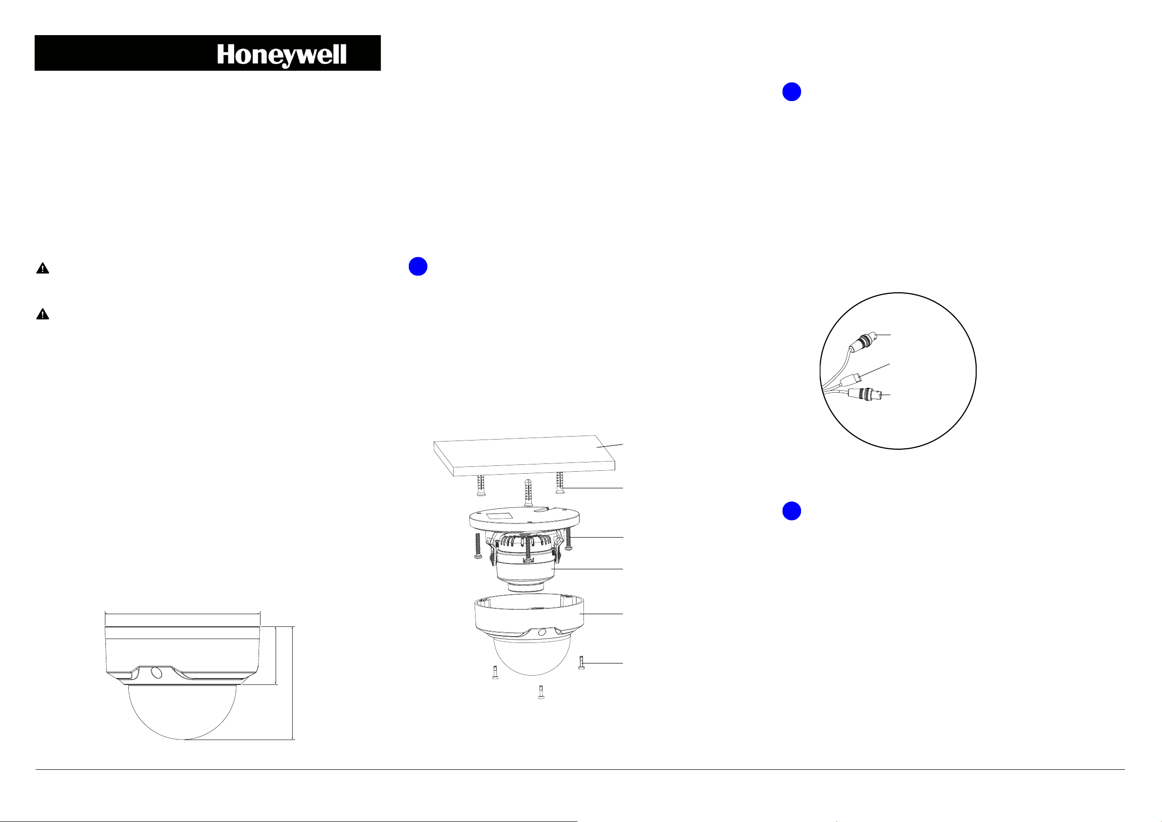
1
Self-tapping screw
Plastic anchor
Mounting surface
Camera assembly
Security screw
Dome cover
2
BNC (Black, HQA)
BNC (Yellow, CVBS)
Power
(12 V DC/24 V AC)
3
Performance Series HQA HD274HD2 1080p
Indoor/Outdoor IR Mini Dome Camera
Quick Installation Guide
Document 800-22070 — Rev B — 05/2016
Thank you for purchasing a Honeywell Performance Series HQA HD274HD2 camera.
Follow the instructions in this guide to install and set up your camera.
Cautions and Warnings
CAUTION This device is configured for 12 V DC/24 V AC operation.
Do not connect to a higher voltage. Use only with NRTL-approved Class 2
power supplies.
CAUTION IR emitted from this product. Do not view directly with
optical instruments. Do not stare directly into the lamp at a distance of less
than 3.3 ft (1 m).
CAUTION Class 1 LED product. Invisible LED radiation (850 nm).
Avoid exposure to beam.
Before You Begin
Before you begin, check that you have received all of the parts listed below. If any parts
are missing or damaged, contact your dealer immediately.
• Camera • Self-tapping screws (4)
• Quick Installation Guide • Plastic anchors (4)
• Mounting template sticker • Power connector
• Allen key (L-wrench)
Tools needed (not supplied):
• Cordless drill • Phillips screwdriver
Preparing the Mounting Surface
1. Inspect the site where you want to install the camera. The mounting surface must be
flat and capable of supporting at least three times the weight of the camera.
2. Remove the backing from the mounting template sticker and affix the sticker to the
mounting surface.
Note If you are using the side exit for the cable, note the orientation of the cable
exit notch. In outdoor installations the notch should point downwards to
prevent water from entering the camera housing.
Mounting the Camera
1. Using the supplied Allen key, remove the dome cover from the camera assembly
and set it aside.
2. Connect the power and video cables.
a. Connect the power connector of the camera to a 12 V DC/24 V AC power source.
b. Make one of the following video cable connections:
• Connect the black BNC connector of the camera to a coaxial video cable
to get an HD (HQA) signal.
• Connect the yellow BNC connector of the camera to a coaxial video cable
to get an SD (CVBS) signal.
• Connect both black and yellow BNC connectors to two coaxial video
cables to get both HD and SD signals.
Note When WDR is enabled, only the HD signal will be available.
Important Safeguards
• Read and keep these instructions.
• Do not aim the camera toward a bright light source for extended periods to prevent
damage to the imager. Avoid operating the unit under or close to unstable light
sources or close to fluorescent lamps or objects reflecting light.
• Do not touch the camera lens.
• Do not drop the camera or subject it to physical shock.
• Do not use a strong or abrasive detergent when cleaning the camera.
• Avoid operating or storing the unit in extremely humid, dusty, or environments
where the operating temperature is outside the recommended range of –22°F to
140°F (–30°C to 60°C).
Dimensions
3. Drill three screw holes at the locations indicated on the mounting template sticker
and insert the three supplied plastic anchors in the holes.
3. Attach the camera assembly to the mounting surface using the supplied screws.
Aiming the Camera and Adjusting Zoom and Focus
1. Aim the camera lens in the desired direction.
2. Set the lens zoom and focus.
a. Connect the camera to a Honeywell Performance Series HQA DVR.
b. Log on to the DVR as the admin user. The default user name is admin
(case-sensitive) and the default password is 1234.
4. If you are flush mounting the camera and want to store the cables inside the wall or
ceiling, drill a hole at the cable exit position on the mounting template and then pull
the power and video cables through the hole.
Document 800-22070 – Rev B – 05/2016
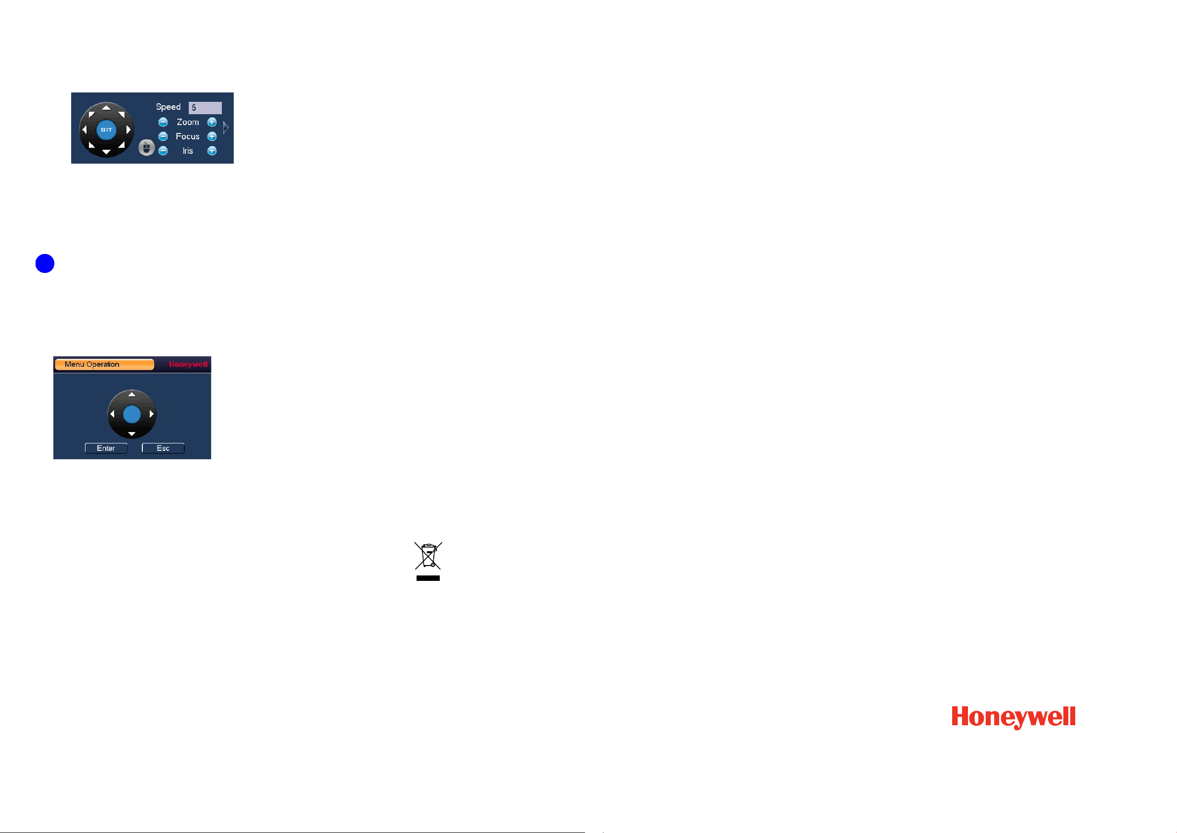
c. Right-click to display the shortcut menu, and then click Pan/Tilt/Zoom.
4
The following panel appears:
•Click Zoom+ or Zoom– to zoom in or out.
•Click Focus+ or Focus– to focus near or far, or click Iris – to enable auto
focus.
3. Attach the dome cover and remove the protective film from the bubble.
Configuring the Camera Settings
1. With the camera connected to a Performance Series HQA DVR, log on to the DVR
as the admin user. The default user name is admin (case-sensitive) and the default
password is 1234.
2. Right-click to display the shortcut menu, and then click Camera Menu. The
following menu operation interface appears.
Regulatory Statements
FCC Compliance
Information to the User This equipment has been tested and found to comply with the
limits for a Class B digital device, pursuant to part 15 of the FCC Rules. These limits are
designed to provide reasonable protection against harmful interference in a residential
installation. This equipment generates, uses and can radiate radio frequency energy and,
if not installed and used in accordance with the instructions, may cause harmful
interference to radio communications. However, there is no guarantee that interference
will not occur in a particular installation. If this equipment does cause harmful interference
to radio or television reception, which can be determined by turning the equipment off
and on, the user is encouraged to try to correct the interference by one or more of the
following measures:
• Reorient or relocate the receiving antenna.
• Increase the separation between the equipment and receiver.
• Connect the equipment into an outlet on a circuit different from that to which the
receiver is connected.
• Consult the dealer or an experienced radio/TV technician for help.
Note Changes or modifications not expressly approved by the party responsible for
compliance could void the user’s authority to operate the equipment.
Canadian Compliance
This Class B digital apparatus complies with Canadian ICES-003.
Cet appareil numérique de la Classe B est conforme à la norme NMB-003 du Canada.
3. Click Enter to show the camera’s OSD menu.
4. To configure the camera settings, do the following:
• Click the up or down arrows to navigate through the menu list.
• Click the left or right arrows to change a setting.
•Click Enter to enter a submenu ( ) or execute a command.
5. After you have configured the camera, right-click to exit the menu operation
interface.
Manufacturer’s Declaration of Conformance
North America The equipment supplied with this guide conforms to UL 60950-1 and
CSA C22.2 No. 60950-1.
Europe The manufacturer declares that the equipment supplied is compliant with the
European Parliament and Council Directive on the restriction of the use of certain
hazardous substances in electrical and electronic equipment (2011/65/EU) and the
essential requirements of the EMC directive (2014/30/EU), conforming to the
requirements of standards EN 55022 for emissions, EN 50130-4 for immunity, and EN
60950-1 for electrical equipment safety.
This is a Class B product. In a domestic environment this product may cause radio
interference in which case the user may be required to take adequate measures.
WEEE (Waste Electrical and Electronic Equipment). Correct disposal of this
product (applicable in the European Union and other European countries with
separate collection systems). This product should be disposed of, at the end of
its useful life, as per applicable local laws, regulations, and procedures
© 2016 Honeywell International Inc. All rights reserved. No part of this publication may be reproduced by any means without written permission from Honeywell. The information in this publication is believed
to be accurate in all respects. However, Honeywell cannot assume responsibility for any consequences resulting from the use thereof. The information contained herein is subject to change without notice.
Revisions or new editions to this publication may be issued to incorporate such changes.
www.honeywell.com/security
+1 800 323 4576 (North America only)
https://www.honeywellsystems.com/ss/techsupp/index.html
Document 800-22070 – Rev B – 05/2016
 Loading...