

Page 1
Page 2

Page 3

Contents
Overview 3
Application 3
Operating elements and display 4
Start-up 5
Inserting batteries (optional) 5
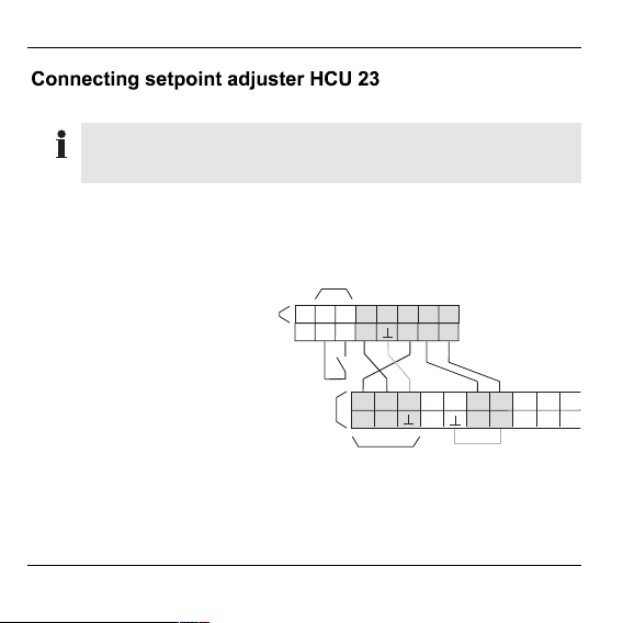
Connecting setpoint adjuster HCU 23 6
Assigning temperature zone 7
Installation 10
Dimensions 11
Operation 12
Changing operating mode 12
Changing setpoint temperature with adjustment dial 13
Disabling setpoint adjuster (child-proofing) 13
Adjusting settings 14
Temperatures and control periods 14
Factory settings 15
Adjusting comfort and economy temperatures 15
Adjusting heating and economy periods 16
Setting date and time 19
Restoring factory settings 20
Informing customers 20
1
Page 4

Contents
Glossary 21
Technical data 22
Help with problems 23
Notes 25
2
Page 5
Overview
For your information
Technical terms are explained in the glossary (Page 20). They are
identified in the text by an *.
The setpoint adjuster HCU 23 is a component of the storey controller
system HCE 40 from Honeywell. It controls the setpoint temperature*
of a room. To do so, it measures the temperature in the room and
sends the setpoint temperature information to the storey controller
HCE 40. The setpoint adjuster is equipped with a series of convenient
functions:
• You can set your own times and choose from two different setpoint
temperatures to set up your own heating programme for each day
of the week
• The unit can be switched between automatic mode* and manual
mode* at any time
• Integrated room temperature sensor
• Automatic switching between summer/winter time
Scope of supply
• Setpoint adjuster
• Operating instructions
3
Page 6
Overview
À
Á
Å
Â
Ã
Ä
Æ
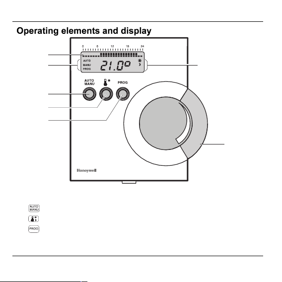
1. Display of the set heating and economy period*
2. Display of the operating mode: AUTO, MANU or PROG
button for changing between AUTO and MANU mode
3.
button for setting the comfort and economy temperature*
4.
5.
button for setting the time program*
6. Display of the comfort or economy temperature
7. Adjustment dial for setting the setpoint temperature or time
4
Page 7
Start-up
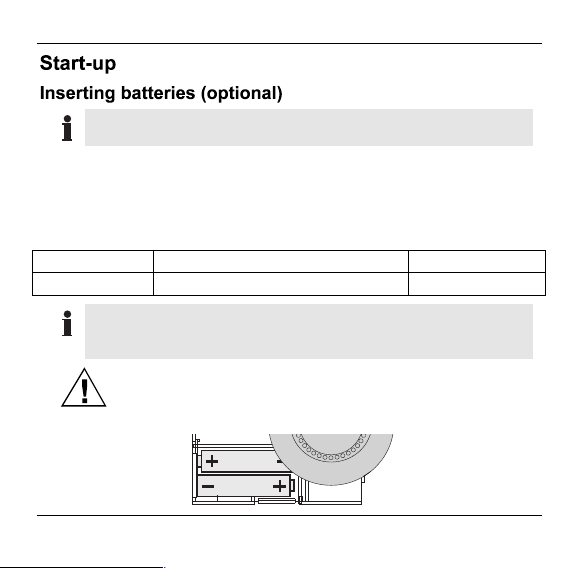
Batteries are not included in the scope of supply.
Batteries allow the unit to function in the event of a power failure. If
batteries are not inserted, the time must be reset after a power failure.
► Open the housing by pressing in the latching nose on the bottom of
the housing while lifting thecover at the same time.
► Use the following batteries types only:
Type Designation Battery life
Mignon battery Alkaline-manganese LR6 AA AM3 2 years
Batteries may not be disposed of with household garbage.
You may be required by local law to dispose of discharged
batteries in a certain manner.
Ensure that the polarity is correct!
Caution!
5
Page 8
Start-up
Setpoint adjusters of type HCU 23 are hard-wired.
Observe the zoning plan* of the storey controller and the
switching of the time programs when connecting the setpoint
adjuster.
Example: Connection to
temperature zone 5
1. Setpoint adjuster
HCU 23
2. HAC 30
(window contact)
3. Storey controller HCE 40
À
Á
456321
78
RF
P1
P2
TW
(connectors 13 to 25)
4. Temperature zone 5
TW Temperature
selector input
RF Room sensor input
KR Boiler regression
Â
13 14 15 16 17 18 19 20 21 22
TW KR B- B+B+
RF
Ã
Px Voltage supply
13.8 V AC
⊥ Ground
6
P2
P1
Page 9
Start-up
You can assign each temperature zone* of the storey controller to the
setpoint adjuster. Connection and assignment occur via the cabling.
The HCU 23 functions as a setpoint adjuster* and time program
transmitter*.
Assigning setpoint adjuster as setpoint transmitter
► Lay out the zoning plan* of the storey controller.
► Attach the connector of the setpoint adjuster to the connectors of the
storey controller as shown in the diagram on the following page.
If you are using only one four-lead cable, you must bridge
terminal 19 to a ground connection (e.g. terminal 17). You can
renounce the ground connection of the storey controller
(terminal 5).
7
Page 10

Start-up
1. Storey controller HCE 40
(connectors 1 to 12)
2. Temperature zone 1
3. Temperature zone 2
4. Temperature zone 3
5. Temperature zone 4
6. Setpoint adjuster HCU 23
Á
TW RF
À
123456789101112
7. Window contact HAC 30
8. Storey controller HCE 40
(connectors 13 to 25)
9. Temperature zone 5
TW Temperature selector input
RF Room sensor input
⊥ Ground
Â
ÃÄ
TW RF TW RF
TW RF
Å
45631782
Æ
Æ
456321
Å
Ç
78
13 14 15 16 17 18 19 20 21 22 23 24
TW RCKR B- B-B+B+
RF
P2
P1
25
PR
È
8
Page 11

Start-up
2
Connecting window contact HAC 30 (optional)
A connected window contact can only be deactivated by
resetting to the factory settings (see "Restoring factory settings"
on Page 20).
► Attach the connector of the setpoint adjuster (if only one is intended)
to the connectors of the storey controller as shown in the following
diagram.
1. Setpoint adjuster
HCU 23
2. HAC 30
(window contact)
À
Á
456321
78
RF
P1
P2
TW
3. Storey controller
HCE 40
(connectors 13 to 25)
Â
13 14 15 16 17 18 19 20 21 22
TW KR B-BB+B+
RF
P1
P2
9
Page 12

Installation
Final installation is not to be carried out until start-up has been
fully completed.
► Mark and drill the fastening holes as shown in the drilling
scheme.
► Screw on the setpoint adjuster.
► Insert the batteries (optional).
► Position the housing cover correctly at the top and latch it into the
latching nose on the housing bottom.
Start-up is complete.
10
Page 13

Installation
11
Page 14

Operation
The setpoint adjuster has 3 operating modes:
• Automatic mode (AUTO)
• Manual mode (MANU)
• Programming mode* (PROG)
The automatic mode is the standard mode of the setpoint adjuster.
Temperatures and heating periods* are controlled by the time
program. "AUTO" is displayed.
Changing to manual operating mode
Changes to the setpoint temperature can be carried out with the
adjustment dial in manual mode. The time program is inactive, and the
temperature set manually remains active until the unit is switched to
automatic mode again.
► Press the button.
"MANU" is displayed.
Changing to programming mode
You can adjust the time program to your own requirements in
programming mode. For further information, please refer to "Adjusting
settings" from Page 13.
► Press the button.
"PROG" is displayed.
12
Page 15

Operation
You can also change the setpoint temperature in automatic mode with
the adjustment dial at any time. The change remains in effect until it is
overwritten by a heating or economy period of the time program.
HINT: When on holiday: Change to manual mode and set a setpoint
with the adjustment dial. This remains constant during your absence.
You can set the currently valid setpoint temperature within the range
of 12 °C to 28 °C. The adjustment dial does not have a stop.
Disabling setpoint adjuster
► Keep the and buttons pressed simultaneously for at least 2
seconds.
" is displayed. Turning the adjustment dial does not change
"
the setpoint.
Enabling setpoint adjuster
► Keep the and buttons pressed simultaneously for at least 2
seconds.
The standard display appears. The setpoint adjuster can be
operated again.
13
Page 16

Adjusting settings
You can exit the menus by pressing the button. The
setpoint adjuster then returns to automatic mode. All changes
are rejected.
The HCU 23 changes between 2 setpoint temperatures...
• Comfort temperature*
• Economy temperature
Normal living temperature
During absence or at night
... and 2 periods:
• Heating period Heating to comfort temperature
• Economy period Lowering to economy temperature
14
Comfort temp.
Economy
temperature
Heating
period
Economy
period
Time program with two heating and economy periods
Page 17

Adjusting settings
Comfort temp.
Economy
temperature
21 °
16 °
Heating
period
6:00 22:00
Economy
period
► Press the button.
The current comfort temperature is displayed flashing.
► Turn the adjustment dial until the desired comfort temperature is
displayed.
► Press the button again.
The current economy temperature is displayed flashing.
► Turn the adjustment dial until the desired economy temperature is
displayed.
► Press the button again.
The comfort and economy temperatures have been changed.
The setpoint adjuster returns to automatic mode.
15
Page 18

Adjusting settings
You can set a first heating and economy period and, if required, a
second one for each weekday.
Each heating period must also have an economy period
assigned to it.
HINT: First adjust the heating and economy period for all the
weekdays simultaneously. If necessary, change the heating and
economy period of individual days in the next step.
Changing heating and economy period for all weekdays
simultaneously
► Press the button.
The following text is displayed:
► Press the button again.
1-7
.
The current first heating period is displayed (e.g. 6.00).
► Turn the adjustment dial until the desired heating period is displayed.
► Press the button again.
► Turn the adjustment dial until the desired economy period is displayed.
► Press the button again.
If you do not want to set a second heating and economy period:
► Turn the adjustment dial until
► Press the button.
--:--
is displayed.
16
Page 19

Adjusting settings
► Turn the adjustment dial until
► Press the button.
--:--
is displayed.
The new heating and economy periods are effective for all the
weekdays.
If you want to set a second heating and economy period:
► Turn the adjustment dial until the desired second heating period is
displayed.
► Press the button again.
► Turn the adjustment dial until the desired second economy period is
displayed.
► Press the button again.
The second heating and economy period is effective for all the
weekdays.
Changing heating and economy periods for a single weekday
► Press the button.
► Turn the adjustment dial until the desired weekday is displayed.
The values have the following meaning: 1 Monday, 2 Tuesday etc. to
7 Sunday.
► Press the button.
The desired weekday is selected.
► Turn the adjustment dial until the desired first heating period is
displayed.
17
Page 20

Adjusting settings
► Press the button again.
► Turn the adjustment dial until the desired first economy period is
displayed.
► Press the button again.
If you do not want to set a second heating and economy period:
► Turn the adjustment dial until
► Press the button.
► Turn the adjustment dial until
► Press the button.
► Press the button.
--:--
--:--
is displayed.
is displayed.
The new first heating and economy period is effective for the
desired weekday.
If you want to set a second heating and economy period:
► Turn the adjustment dial until the desired second heating period is
displayed.
► Press the button again.
► Turn the adjustment dial until the desired second economy period is
displayed.
► Press the button again.
► Press the button.
The new heating and economy period is effective for the desired
weekday.
18
Page 21

Adjusting settings
Deleting heating and economy period
Whenever a heating period is deleted, the corresponding
economy period must also be deleted and vice versa.
► Proceed as described in the above sections on "Changing heating
and economy periods". Turn the adjustment dial to the right until
--:--
is displayed.
The time program is only functional when heating and economy
periods are defined.
You must set the data and time:
• upon first start-up
• after a power failure or after switching on.
The current year flashes. The output setpoint corresponds to the
last valid setpoint (no battery buffering).
► Keep the button pressed for at least 2 seconds.
A four-digit number – the year – flashes in the display.
► Turn the adjustment dial until the current year is displayed.
► Press the button.
Two digits flash in the display for the month.
► Turn the adjustment dial until the current month is displayed.
19
Page 22

Informing customers
► Press the button.
► Adjust the day, hour and minute by the same method until the
current setpoint temperature is displayed.
The date and time are set.
All settings are lost when you restore the factory settings of the
setpoint adjuster HCU 23.
► Remove the batteries from the setpoint adjuster.
► Hold down the button and switch on the voltage supply.
After start-up is complete and any setting adjustments have been
made, it is advisable that the basic operation of the setpoint adjuster
will be explained to customers.
► Explain the difference between the manual and automatic modes.
► Also explain how this difference relates to the operation of the storey
controller.
► Inform them of the ease of use resulting from the two modes.
20
Page 23

Glossary
Automatic mode
Standard operating mode of the
setpoint adjuster. The time program
controls the room temperature.
Heating period
Period in which the comfort
temperature is effective.
Programming mode
Operating mode for adjusting
settings such as the date and time,
heating and economy period.
Setpoint temperature
The room temperature which is to be
reached.
Setpoint adjuster
Function of the setpoint adjuster in
manual mode.
Economy temperature
Set temperature accessed by the
time program. Advisable at night or
during absence. Refer to comfort
temperature.
Comfort temperature
Set temperature accessed by the
time program. Refer to economy
temperature.
Manual mode
No time program active. Setpoint
adjustment via adjustment dial.
Economy period
Period in which the economy
temperature is effective.
Temperature zone
Area of the home which was
assigned its own heating schedule.
Corresponds to a room in this case.
Time program
Combination of setpoints and
switching points.
Time program transmitter
Setpoint adjuster in automatic mode.
The time program controls the room
temperature.
Zoning plan
Overview of the temperature zones
of the storey controller.
21
Page 24

Technical data
Sensor element NTC termistor
Resistor 20 kOhm at 25 °C
Operating range 0°Cto+40°C
Dimensions (H x W x D)
Type of installation Wall installation
Max. ambient temperature / humidity 0°Cto50°C/5%to90%rel.
Max. storage temperature / humidity –20 °C to +65 °C / 5 % to 90 % rel.
Voltage supply 9 – 13.5 V AC / DC
Protection type IP 30 DIN 40 050 / IEC 144
Time program
Setpoints
Setting precision 0.5 K
Window contact HAC 30 optionally connectable
103 × 98 × 28 mm
humidity
Humidity
1 week program, 4 switching points
per day
1 day and 1 night setpoint
selectable: 12 °C to 28 °C
22
Page 25

Help with problems
Problem/
Display
No display
(year) flashes
Cause Remedy
Setpoint adjuster not
connected properly
No power to storey
controller HCE 40
► Connect setpoint
adjuster correctly.
► Connect HCE 40 to
voltage supply
or
► Check voltage
supply.
Power failure
► Set time after
changing the
batteries.
Setpoint adjuster
disabled. Operation not
► Enable setpoint
adjuster.
possible
Unit defective
► Inform dealer.
23
Page 26

Help with problems
Problem/
Display
24
Cause Remedy
Window contact opened
► Close window
or
► Replace window
contact
or
► Install a jumper to
disable window
contact
or
► Restore factory
settings.
Page 27

Notes
25
Page 28

Honeywell AG
Böblinger Straße 17
D – 71101 Schönaich
Tel. (01801) 466 390
This company is certificated to
The right is reserved to make modifications. This document is definitive for the
enclosed product and replaces all previous publications.
No. 7157589 EN1H-0187 GE51 R0701
 Loading...