

Page 1

HCS544
Day/Night
Color Camera
NTSC
HCS544 HCS544X
User Guide
Document 800-01123 – Rev B – 02/08
PAL
Page 2

Revisions
Issue Date Revisions
A 01/08 New document
B 02/08 Amended specifications, page 21: changed
power consumption to 3.5 W; added lens
connector; removed ALC.
2
Page 3
Warnings
Installation and servicing should be performed only by
qualified and experienced technicians to conform to all local
codes and to maintain your warranty.
WARNING! 12 VDC/24 VAC models require the use of
CSA Certified/UL Listed Class 2 power
adapters to ensure compliance with
electrical safety standards.
Caution To reduce the risk of fire or shock hazard, do not
expose this camera to rain or moisture.
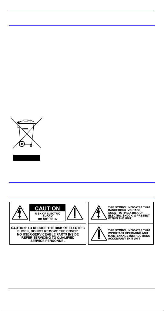
WEEE (Waste Electrical and Electronic
Equipment). Correct disposal of this product
(applicable in the European Union and other
European countries with separate collection
systems). This product should be disposed of,
at the end of its useful life, as per applicable
local laws, regulations, and procedures.
Explanation of Graphical Symbols
Document 800-01123 Rev B 3
02/08
Page 4

FCC Compliance Statement
Information to the user: This equipment has been tested
and found to comply with the limits for a Class A digital
device, pursuant to Part 15 of the FCC Rules. These limits
are designed to provide reasonable protection against
harmful interference when the equipment is operated in a
commercial environment. This equipment generates, uses,
and can radiate radio frequency energy and, if not installed
and used in accordance with the instruction manual, may
cause harmful interference to radio communications.
Operation of this equipment in a residential area is likely to
cause harmful interference in which case the user will be
required to correct the interference at his own expense.
Caution Changes or modifications not expressly
approved by the party responsible for
compliance could void the user’s authority to
operate the equipment.
This Class A digital apparatus complies with Canadian ICES-
003.
Cet appareil numérique de la Classe A est conforme à la
norme NMB-003 du Canada.
Manufacturer’s Declaration of
Conformance
The manufacturer declares that the equipment supplied with
this guide is compliant with the essential protection
requirements of the EMC direction 89/336/EEC and the Low
Voltage Directive LVD 73/23 EEC, conforming to the
requirements of standards EN 55013 for emissions, EN
50130-4 for immunity, and EN 60065 for Electrical
Equipment safety.
4
Page 5

Contents
Introduction . . . . . . . . . . . . . . . . . . . . . . . . . . . . . . 6
Features . . . . . . . . . . . . . . . . . . . . . . . . . . . . . . 6
Before You Begin . . . . . . . . . . . . . . . . . . . . . . . . . 6
Unpack Everything . . . . . . . . . . . . . . . . . . . . . 6
Installation . . . . . . . . . . . . . . . . . . . . . . . . . . . . . . 7
Installing the Lens . . . . . . . . . . . . . . . . . . . . . . 7
Adjusting the Flange Back Focus . . . . . . . . . . . . 8
Connecting Monitor and Power . . . . . . . . . . . . . . 8
Mounting the Camera . . . . . . . . . . . . . . . . . . . . . 9
Making Final Adjustments . . . . . . . . . . . . . . . . . . 9
Programming . . . . . . . . . . . . . . . . . . . . . . . . . . . . 10
OSD Menu Controls . . . . . . . . . . . . . . . . . . . 10
SETUP Menu . . . . . . . . . . . . . . . . . . . . . . . . . . . 11
SETUP Menu Functions . . . . . . . . . . . . . . . . 12
SPECIAL Menu . . . . . . . . . . . . . . . . . . . . . . . . . . 14
SPECIAL Menu Functions . . . . . . . . . . . . . . . 15
Adding a Camera Title Display . . . . . . . . . . . 16
Sync Control/Line-lock Setup . . . . . . . . . . . . 17
Motion Detection Setup . . . . . . . . . . . . . . . . . 18
Privacy Mode Setup . . . . . . . . . . . . . . . . . . . 19
Warranty and Service . . . . . . . . . . . . . . . . . . . . . 20
Specifications . . . . . . . . . . . . . . . . . . . . . . . . . . . 21
Document 800-01123 Rev B 5
02/08
Page 6

Introduction
The Honeywell HCS544 Day/Night Color Camera is
designed for general surveillance applications and is ideally
suited for low-light indoor environments. An intuitive menu
and Graphical User Interface (GUI) helps you quickly set up
the camera to ensure the best picture quality for your unique
environment. It requires little or no adjustment after initial
installation.
Features
• High resolution 540 TVL 1.3” CCD provides a high
quality picture in low-light conditions
• Digital noise reduction (DNR) minimizes video noise in
low light
• Automatic day/night switching with adjustable threshold
level control
• 12 VDC or 24 VAC operation
Before You Begin
Please read this guide carefully before you install the
HCS544 Day/Night camera. Keep this guide for future
reference.
Unpack Everything
Check that the items received match those listed on the
order form and packing slip. The HCS544 packing box
should include, in addition to this user guide, one HCS544
camera.
If any parts are missing or damaged, contact the dealer you
purchased the camera from or call Honeywell Customer
Service (see the back of this guide for contact information).
Note You will also require a Phillips screwdriver and a
flathead screwdriver to complete the installation.
6
Page 7
Installation
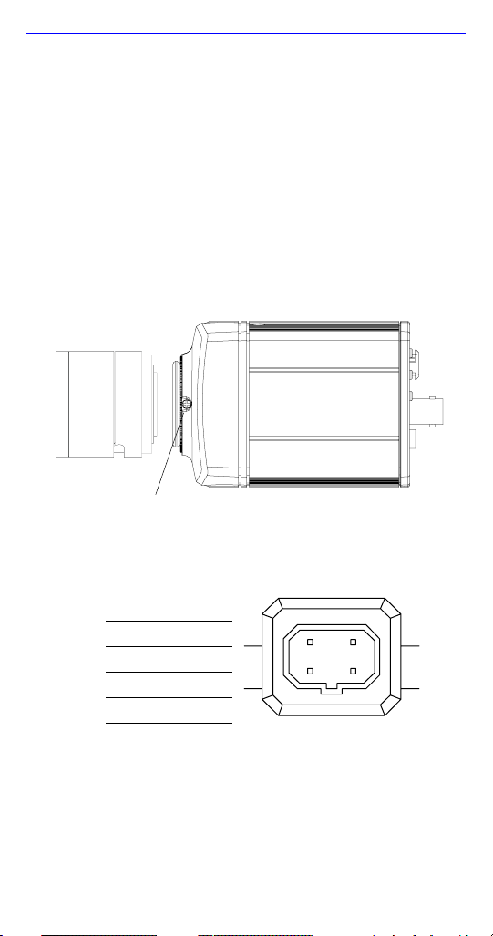
Installing the Lens
The HCS544 Series camera is factory configured for a CSmount lens.
Follow Figure 1 to attach a customer supplied lens, screw
the lens
! into the front of the camera body ".
Figure 1 CS Mount
"
!
Setscrew
Figure 2 Pin Definitions
Pin DC Lens
1CTRL 2CTRL +
3DRV +
4DRV -
Document 800-01123 Rev B 7
02/08
3
4
12
Page 8
Adjusting the Flange Back Focus
The back focus adjustment is accessible at the front end of
the camera housing to adjust the back focal length or
picture focus.
1. Loosen the setscrews with a Phillips screwdriver.
2. Adjust the focus ring to focus the picture.
3. Retighten the setscrew.
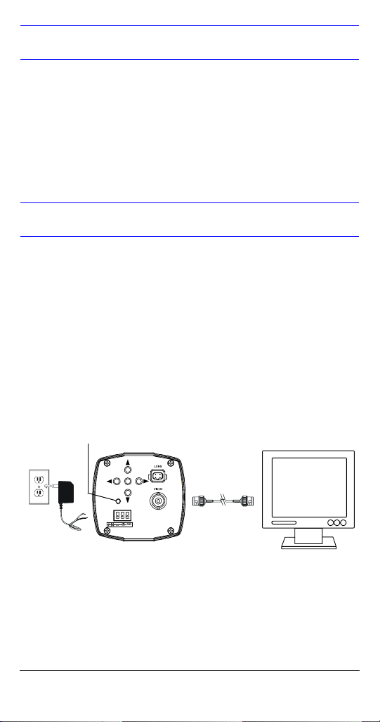
Connecting Monitor and Power
Note Check the power source from the external power
supply before applying power to the camera.
1. Connect the VIDEO connector on the rear of the camera
to the video-in connector on your monitor.
2. Connect the camera to a 12 VDC or 24 VAC power
supply (appropriate to your installation). Use a
screwdriver to first loosen the ~AC24V/DC12V terminal
screws on the terminal block.
Figure 3 Video Connections
Power LED
ENTER
+
Note To ease installation, the terminal block can be
removed. The power connections of the removable
terminal block are not polarity-sensitive. Connect
either power lead to either connector terminal.
8
Page 9

3. Secure the power leads by retightening the terminal
screws until snug.
4. Plug the power supply into an appropriate power
source. The power LED illuminates to show that the
camera is receiving power. If it does not illuminate,
check the removable terminal block connections and
the power source.
Mounting the Camera
Mounting points are provided on the top and bottom of the
camera and are used to mount the camera on a bracket or
tripod. They are designed to accept standard sized
mounting bolts. The mounting bracket must be capable of
supporting the weight of the camera and its lens.
Caution Some installation codes dictate that the
mounting bracket must be capable of
supporting up to four times the combined weight
of the camera and lens.
Making Final Adjustments
Adjust the focus in your field of view; that is, until you see a
clear image. If necessary, adjust the brightness using the
OSD menu controls (see ”LENS DC/Brightness’ - DC/
BRIGHTNESS or ”AGC (Automatic Gain Control) DC/Brightness’ on
page 12). Confirm the exposure on the monitor screen.
Document 800-01123 Rev B 9
02/08
Page 10

Programming
Use the OSD (On-Screen Display) to program the camera.
OSD Menu Controls
Figure 4 OSD Menu Control
Navigating through the menus
ENTER (SET)
Press to access the SETUP
ENTER
ENTER
+
MENU.
Press to enter a screen or
select a menu option.
!, "
Move horizontally to and
between menus and options.
#, $
Move vertically to and between
menus and options.
%” indicates submenus.
“
Select the menu, then press
ENTER.
Select RETURN, then press
ENTER, to return to the
previous menu.
Select EXIT, then press ENTER,
to save your changes. Settings
remain in effect when power is
turned off, then on again.
When no buttons are pressed, the menu display turns off
automatically after 70 seconds.
10
Page 11

SETUP Menu
The HCS544 menu system consists of one main SETUP
menu (see Figure 5) for easy camera programming.
Figure 5 Menu Structure
1
LENS DC%
2
SHUTTER – – –
3
WHITE BAL. ATW
4
BACKLIGHT OFF
5
AGC HIGH%
6
DNR MIDDLE
7
DSS AUTO
8
SPECIAL%
9
EXIT MENU
<<SETUP>>
% indicates submenus
SETUP Menu
See ”SETUP Menu
Functions” on
a description of the submenus and menu options.
page 12 for
LENS
SHUTTER
WHITE BAL
BACKLIGHT
AGC
DNR
DSS
SPECIAL%
Menu OptionsSubmenu
DC%
MANUAL
FLK
ESC%
MANUAL
ATW
MANUAL%
AWC%
OFF
LOW
MIDDLE
HIGH
OFF
LOW%
MIDDLE%
HIGH%
OFF
LOW
MIDDLE
HIGH
OFF
%
AUTO
See ”SPECIAL Menu”
page 14.
on
Document 800-01123 Rev B 11
02/08
Page 12

SETUP Menu Functions
Menu Item Option Description
1 LENS DC
2 SHUTTER FLK
3 WHITE BAL.
(White
Balance)
4 BACKLIGHT OFF
5 AGC
(Automatic
Gain Control)
%
MANUAL
ESC
%
MANUAL
ATW
MANUAL
AWC%
LOW
MIDDLE
HIGH
OFF
LOW
%
MIDDLE%
HIGH%
Selects Lens type.
Press ENTER with DC selected to
access “BRIGHTNESS” for iris
level adjustment.
Adjusts shutter settings.
Flickerless mode (FLK) reduces
on-screen flickering.
Electronic Shutter Control (ESC)
adjusts brightness level on screen
when using a manual lens.
Manual mode allows you to adjust
the shutter speed from
1/60-1/120,000 of a second
(NTSC), or 1/50-1/120,000 (PAL).
Controls color on the screen.
%
Select Auto Tracing White Balance
(ATW) when the color temp is
1800°K-10500°K (for example
when under a fluorescent light, or
outdoors).
Manual mode allows you to
increase or decrease the red or
blue GAIN on screen.
Select Auto White Balance Control
(AWC), then press ENTER to
automatically adjust the white
balance to your specific
environment.
Provides light level control to
overcome severe
backlighting conditions.
Adjusts value of AGC gain.
Increase the GAIN level to
brighten the picture in low light
conditions (noise/distortion may
develop). The submenu provides
access to the brightness control.
12
Page 13

Menu Item Option Description
6 DNR
(Digital Noise
Reduction)
OFF
LOW
MIDDLE
HIGH
Reduces noise on the screen.
Increasing the DNR level reduces
noise but may introduce video
artifacts. DNR is deactivated if
AGC is turned off.
7 DSS
(Digital Slow
Shutter)
OFF
AUTO
Automatically provides a clear
image under low-light
%
conditions. You can control the
maximum low-light
magnification from 2x to 128x
(increasing magnification may
cause noise/distortion). DSS is
deactivated when
SHUTTER is set to FLK mode.
8 SPECIAL
% Takes you to the SPECIAL menu
(see next section).
10 EXIT Exits the SETUP menu and returns
to video monitoring.
Document 800-01123 Rev B 13
02/08
Page 14

SPECIAL Menu
1. On the SETUP menu, press the menu control UP or
DOWN and then select SPECIAL.
2. Press the ENTER (SET) control to access the SPECIAL
menu.
Figure 6 SPECIAL Menu
1
2
3
4
5
6
7
8
9
% indicates submenus
<<SPECIAL MENU>>
CAMERA ID OFF
DAY/NIGHT AUTO
SYNC INT
MOTION DET OFF
PRIVACY OFF
MIRROR OFF
SHARPNESS ON%
RESET
RETURN%
SPECIAL Menu
For a description of the
submenus and menu options,
”SPECIAL Menu Functions” on
page 15.
Submenu
CAMERA ID
DAY/NIGHT
SYNC
MOTION DET
PRIVACY
MIRROR
SHARPNESS
RESET
Menu
Options
OFF,
ON%
AUTO,
COLOR
INT
(L/L)
OFF,
ON%
OFF,
ON%
OFF,
ON
ON%,
OFF
14
Page 15

SPECIAL Menu Functions
Menu Item Option Description
1 CAMERA ID OFF
2 DAY/NIGHT AUTO
3SYNC INT
4MOTION DET OFF
5PRIVACY OFF
6MIRROR OFF
7SHARPNESS ON
8 RESET Restores all factory default
9RETURN
ON
%
COLOR
L/L
%
ON
%
ON
%
ON
%
OFF
% Returns to the main SETUP menu.
Sets a name to be displayed on
the monitor. See
”Adding a
Camera Title Display DC/Brightness’
Sets the camera to either
automatic color/black and white or
full-time color mode.
Synchronizes the vertical interval
sync pulse of your camera with
other equipment to reduce the
effect of picture roll on the
monitor.
In Line Lock (L/L) mode you can
adjust the phase from 0–359
Detects moving objects on screen,
and displays
DETECTED
detected.
Allows you to select the area on
screen you want to observe. See
MOTION
when movement is
”Motion Detection Setup DC/
Brightness’
Allows you to mask certain areas
of the screen from observation.
Produces a horizontal mirror
image on screen.
Sharpens the image on screen.
You can adjust the sharpness level
from 0–31 (excessive sharpening
may cause picture noise to
develop).
settings.
.
.
°.
Document 800-01123 Rev B 15
02/08
Page 16

Adding a Camera Title Display
To add a camera title:
1. On the SPECIAL menu, select CAMERA ID and then
press ENTER
Figure 7 Adding Camera Title
2. Press the menu control UP, DOWN, LEFT, or RIGHT to
select a character, then press ENTER (SET) to accept
it. The character is saved and the title cursor at the
bottom of the screen moves to the next position. You
can use the
title name to make changes, and you can also select
CLR to delete the entire title and start again.
3. Repeat step 2 until your camera title is complete.
4. Select POS to position where you would like the
camera title to be located on screen. Select the position
using the menu control, then press ENTER (SET) to
confirm the position.
5. Select END when you are finished.
(SET).
CAMERA ID
A B C D E F G H I J K L M
N O P R Q S T U V W X Y Z
a b c d e f g h i j k l m
n o p q r s t u v w x y z
– . 0 1 2 3 4 5 6 7 8 9
& ' CLR POS END
_ _ _ _ _ _ _ _ _ _ _ _ _ _ _
& ' symbols to go back or forward in the
16
Page 17

Sync Control/Line-lock Setup
This screen allows you to synchronize the vertical interval
sync pulse of your camera with other equipment to reduce
the effect of picture roll on the monitor. Line lock mode is
only available when using 24 VAC power.
Figure 8 Sync Control Setup
<SYNC. CONTROL>
SYNC INT (L/L)
Menu Item Description
INTERNAL When line lock is not required.
LINELOCK Adjust the vertical phase (VPH):
VPH: 000– 359 (factory default is 0)
RETURN Press ENTER (SET) to return to the SETUP menu.
Document 800-01123 Rev B 17
02/08
Page 18

Motion Detection Setup
Set up to four areas of the screen to detect moving objects.
The screen will display MOTION DETECTED when
movement is detected.
Figure 9 Motion Detection Setup
MOTION DETECTION
AREA SEL AREA 1
AREA STATE ON
TOP |..|................| 10
DOWN |........|..........| 25
LEFT |...|...............| 20
RIGHT |........|..........| 40
Press SET to Return
Menu Item Option Description
AREA SEL AREA 1
AREA 2
AREA 3
AREA 4
AREA
STATE
ON
OFF
TOP
DOWN
LEFT
RIGHT
Select which of the four motion
detection grids top left, top right,
bottom left, bottom right) you would like
to modify.
Choose whether to activate or
deactivate the selected grid.
Press LEFT or RIGHT menu control to
alter the dimensions of the selected
grid.
18
Page 19

Privacy Mode Setup
Set up to four areas of the screen for privacy mode (that is,
the camera will not display a masking grid in these areas).
Figure 10 Privacy Mode Setup
PRIVACY
AREA SEL AREA 1
AREA STATE ON
AREA TONE |...............|...| 80
TOP |..|................| 10
DOWN |........|..........| 25
LEFT |...|...............| 20
RIGHT |........|..........| 40
Press SET to Return
Menu Item Description
AREA SEL AREA 1
AREA 2
AREA 3
AREA 4
AREA STATE ON
OFF
AREA TONE Press LEFT or RIGHT menu control to
TOP
DOWN
LEFT
RIGHT
Select which of the four masking grids
(top left, top right, bottom left, bottom
right) you would like to modify.
Choose whether to activate or
deactivate the selected grid.
change the shade of the masking
grids.
Press LEFT or RIGHT menu control to
alter the dimensions of the selected
grid.
Document 800-01123 Rev B 19
02/08
Page 20

Warranty and Service
Subject to the terms and conditions listed on the Product
warranty, during the warranty period Honeywell will repair or
replace, at its sole option, free of charge, any defective
product returned prepaid.
In the event you have a problem with any Honeywell
product, please call Customer Service at 1.800.796.CCTV
(North America only) for assistance or to request a Return
Merchandise Authorization (RMA) number. For Europe
and the United Kingdom, please contact your Honeywell
dealer.
Be sure to have the model number, serial number, and the
nature of the problem available for the technical service
representative.
Prior authorization must be obtained for all returns,
exchanges, or credits. Items shipped to Honeywell
without a clearly identified Return Merchandise
Authorization (RMA) number may be refused.
20
Page 21

Specifications
HCS544 (NTSC) HCS544X (PAL)
Operational
Image Sensor: 1/3” CCD
Video Standard: NTSC PAL
Scanning System: 525/60 lines 625/50 lines
Number of Pixels
(H x V):
Minimum Illumination: 0.3 lux color/0.1 lux B/W
Horizontal Resolution: Greater than 540 TVL
Video Output: 1 Vp-p @ 75 Ohms
Sync System: 12 VDC: Internal
S/N Ratio: 50 dB or more (AGC off)
Auto Gain Control: Off/On, selectable
Automatic Electronic
Shutter:
White Balance: ATW/AWC/Manual
BLC: Off/On, selectable
Gamma: 0.45
Line Lock Phase
Adjustment:
Digital Noise
Reduction:
Digital Slow Shutter: x2~x128
Electrical
Input Voltage: 12 VDC/24 VAC
Input Range: 11– 16 VDC, 17–28 VAC
Surge Suppression: 1.5 kW transient
Power Consumption: 3.5 W (max)
768 x 494 752 x 582
24 VAC: Internal/Line lock
1/60–
1/120,000 sec
Adjustable Line lock vertical phase
Off/Low/Middle/High
1/50–
1/120,000 sec
Document 800-01123 Rev B 21
02/08
Page 22

HCS544 (NTSC) HCS544X (PAL)
Mechanical
Dimensions: See diagram below
Weight: 1.1 lb (.5 kg), camera only
Construction: Housing: extruded aluminum
Housing finish: cool gray powder
coated
Connector: Main Video Output: BNC connector
Lens: 4-pin connector
Power Input: Removable screw
terminal block
Environmental
Temperature: Operating: 14°F to 122°F
(-10°C to 50°C)
Storage: -4°F to140°F
(-20°C to 60°C)
Relative Humidity: 0% to 85%, non-condensing
Regulatory
Emissions: FCC, CE (EN55013)
Immunity: CE (EN50130-4)
Safety: EU: 73/23/EEC LVD
Dimensions
22
3.93” (99.93 mm)
3.36” (85.36 mm)
2.44” (61.90 mm)
2.65” (67.22 mm)
2.44” (61.90 mm)
Page 23

Page 24

www.honeywellvideo.com
+1.800.796.CCTV (North America only)
HVSsupport@honeywell.com
Document 800-01123 – Rev B – 02/08
© 2008 Honeywell International Inc. All rights reserved. No part of this
publication may be reproduced by any means without written permission
from Honeywell Video Systems. The information in this publication is believed
to be accurate in all respects. However, Honeywell Video Systems cannot
assume responsibility for any consequences resulting from the use thereof.
The information contained herein is subject to change without notice.
Revisions or new editions to this publication may be issued to incorporate
such changes.
 Loading...