

Honeywell HCW2S2, HCD3S2, HCD5S2, HCD3S2X, HCW2S2X Quick Installation Manual
...
equIP Series Indoor IP Box Camera Quick Install Guide
* Lens sold separately
CAUTION:TO REDUCE THE RISK OF ELECTRIC SHOCK,
DO NOT REMOVE COVER (O R BACK).
NO USER SERVICEABLE PARTS INSIDE.
REFER SERVICING TO QUALIFIED SERVICE PERSONNEL.
THIS SYMB OL INDICATES
THAT DANGEROUS VOLTAGE
CONSTITUTING A RISK OF
ELECTRIC SHOCK IS PRESENT
WITHIN THE UNIT.
THIS SYMB OL INDICATES THAT
IMPORTANT OPERATING AND
MAINTENANCE INSTRUCTIONS
ACCOMPANY THIS UNIT.
DO NOT OPEN
RISK OF ELECTRIC SHOCK
1
C/CS mount
adapter
2
8
5
9
4
1
2
3
6
7
24 V AC
Pin 1 Power 1
Pin 2 Earth GND
Pin 3 Power 2
12 V DC
Pin 1 Power
Pin 2 Reserved
Pin 3 GND
123
equIP® Series HD Indoor IP Box
Quick Installation Guide
Introduction
Thank you for purchasing a Honeywell equIP®
Series HD Indoor IP Box camera. Follow the
instructions in this guide to install and log in to
your camera. For instructions on configuring the
camera, refer to the equIP
Configuration Guide on the software and
documentation CD that came with your camera.
If you require additional assistance, please call
the number shown on the back cover.
Cautions and Warnings
®
Series IP Cameras
Camera
HCW2S2 HCW2S2X
HCD3S2 HCD3S2X
HCD5S2 HCD5S2X
Document 800-15466V3 — Rev A — 01/2014
• Avoid operating or storing the unit in extremely humid, dusty, hot/cold environments, where the
operating temperature is outside the recommended range of 14°F to 122°F (–10°C to 50°C).
• Avoid operating the unit close to sources of powerful electromagnetic radiation, such as radio or
TV transmitters.
Installing the Camera
Before You Begin
Before you begin, check that you have received all of the parts listed below. If any parts are missing
or damaged, contact your dealer immediately.
•Camera
• Software and documentation CD
• Power terminal block
CAUTION Installation and servicing should be performed only by
qualified and experienced technicians to conform to all local codes
and to maintain your warranty.
Equipment Required for Installation
Before you begin, make sure that you have the following supplied items available to use during
installation:
• C/CS Lens (manual or auto iris) • Indoor camera mounting bracket
Preparing the Camera for Installation
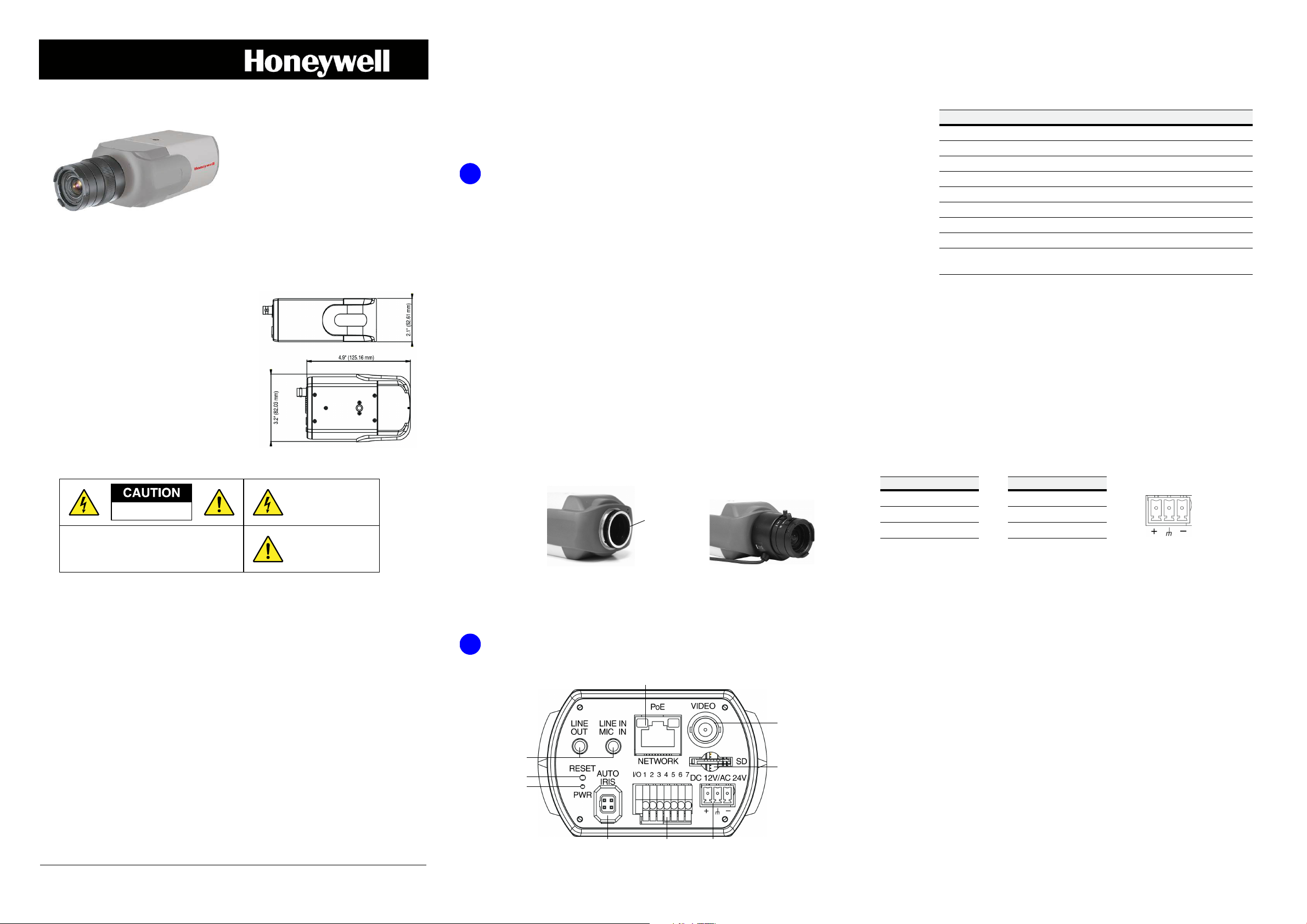
1. Select the lens to use with your camera. The camera supports both manual iris and auto iris
lenses. If using a DC (Direct Drive) lens, it should be connected to the camera with the 4-pin
square socket located on the back panel of the camera. If using a C-mount lens, after
removing the camera’s plastic cover, users need to mount the C/CS mount adapter to the
camera, then attach the lens to the adapter. The C/CS lens mount adapter should be included
with your lens.
• Back focus adjustment key
• Quick install guide
No. Name Description
1 RJ45 10/100 Mbps Ethernet/PoE input
2 VIDEO (BNC) Analog video output
3 MicroSDHC card slot For video recording storage on microSDHC
4 DC 12V/AC 24V 12 V DC / 24 V AC power input
5 Alarm I/O and RS485 Alarm and RS485 connection
6 AUTO IRIS connector Connection for auto iris lenses
7 PWR LED Indicates power connection (green LED)
8 RESET button Restores factory default settings
9 LINE OUT and LINE IN/
MIC IN
Two-way audio connections
Connecting to a Power Source
To power the camera, either Power over Ethernet (PoE) or a 12 V DC or a 24 V AC power connection
can be used.
If you are using PoE to power your camera, connect an Ethernet cable to the camera’s RJ45 Ethernet
port and plug the other end of the cable into an IEEE 802.3af PoE switch.
WARNING
with rated output of 24 V AC / 700 mA minimum or 12 V DC / 800 mA minimum, marked
LPS or Class 2, or by Listed ITE with Power over Ethernet rate 48 V DC / 300 mA.
If you are using a 12 V DC or 24 V AC connection to power your camera, insert the wiring into the
supplied power terminal block and plug the terminal block into the power connector on the camera
back panel. Refer to the following pin definitions when connecting the wiring:
This product is intended to be powered by a Listed power adapter
WARNING
Certified/UL Listed Class 2 power adapters are required. Power over Ethernet (PoE)
shall be provided by listed Information Technology Equipment meeting the IEEE
802.3af PoE standard. The PoE is not intended to be connected to exposed (outside
plant) networks.
To ensure compliance with electrical safety standards, CSA
CAUTION Risk of explosion if Battery is replaced by an incorrect type.
Dispose of used batteries in accordance with local laws.
Important Safeguards
• Read and keep these instructions.
• Please ensure that your installation area can safely support the weight of the camera.
• Do not aim the camera toward an bright light source for extended periods to prevent damage to
the imager. Avoid operating the unit under or close to unstable light sources (may cause
flickering), or close to fluorescent lamps or objects reflecting light.
• Do not touch the camera lens.
• Do not drop the camera or subject it to physical shock.
• Do not use a strong or abrasive detergent when cleaning the camera.
Document 800-15466V3 – Rev A – 01/2014
Connecting to a Network
2. Prepare the mounting equipment. This camera is intended for indoor use. Mount the camera
using a camera bracket for indoor applications. If you choose to mount the camera outdoors,
you must employ a suitable weatherproof enclosure. Follow the mounting equipment
instructions for more information on preparing the camera for mounting.
Connecting the Wiring
Network, power, video, audio, and alarm connections are located on the camera’s rear panel.
If you have not already done so, connect a Cat5 Ethernet cable to the RJ45 connector on the camera
back panel. Connect the other end of the Ethernet cable to a network switch or PC. For best
transmission quality, the Ethernet cable should not be longer than 328 ft (100 m). After you have
connected the Ethernet cable, check the status of the LED indicators on the RJ45 connector.
• A flashing green LED indicates that the camera is connected to a network.
• A flashing orange LED indicates network activity.
If the LEDs are not lit, re-check the Ethernet cable connection.
Note In some cases, you may need use an Ethernet crossover cable when connecting the IP
camera directly to the PC.
Connecting Analog Video
To view ana log video o utput, to h elp whe n aimin g and posit ioning the camera during set up, con nect
a coaxial cable to the BNC connector on the camera back panel and connect the other end of the
cable to an analog monitor.
Connecting Alarm Inputs/Outputs
The camera supports one alarm input and one relay output, as well as an RS485 interface for
connecting a pan and tilt positioning system (pins 6 and 7). Refer to the following pin definitions
when connecting alarm devices:
Connecting Audio Inputs/Outputs
RS485
Pin 5 GND
Pin 6 D–
Pin 7 D+
Alarm
Pin 1 Output+
Pin 2 Output–
Pin 3 Input+
Pin 4 Input–
3
4
Optional
The camera supports two-way audio transmissions. See the back panel image in Connecting the
Wiring to view the audio connections. Connect the audio input device to LINE IN/MIC IN. Connect
the audio output device to LINE OUT.
Completing the Installation
To complete the camera installation, do the following:
1. If you will be using a microSDHC card for video storage, insert the card now into the
microSDHC card slot on the camera back panel (see the back panel image in Connecting the
Wiring). The equIP Series IP cameras support microSDHC cards of up to 32 GB. Push the card
into the slot until it clicks into place. To remove a microSDHC card, push it in to release it from
the slot, then pull it the rest of the way out. See Clip Storage on MicroSDHC Card for more
information on using the microSDHC card with your IP camera system.
2. Make sure the lens and mounting device are installed correctly. Install the camera into the
mounting device by screwing into the mounting screw slot on either the top or bottom of the
camera.
3. Adjust the positioning of the camera as desired. Adjustments available will depend on the
mounting device that is being used.
Note Zoom and focus adjustments can be made from the Honeywell Viewer web client.
4. When positioning is correct, tighten all adjustment points on the mount to lock the camera in
place.
Logging In to the Camera
Before You Log In to the Camera
Before logging in to the camera, ensure that your PC meets the following system requirements:
Operating System Windows XP, Windows Vista, Windows 7 (32/64 bit)
CPU Intel Pentium M, 2.16 GHz or Intel Core 2 Duo, 2.0 GHz
System Memory 2 GB or more
Network Card Minimum: 10Base-T (10 Mbps). Recommended: 100Base-TX (100 Mbps)
Web Browser Microsoft Internet Explorer 6.0 or later, Google Chrome, Mozilla Firefox,
Apple Safari
To run the web client application, you must have Windows administrator privileges and your browser
must be set up to allow ActiveX controls (refer to the equIP
on the software and documentation CD for more information).
Logging In to the Camera
To log in to the camera, do the following:
1. Power up the camera through the PoE/24 V AC/12 V DC power connection.
2. Insert the installation disc into your disc drive and navigate to the Honeywell Device Search
folder.
If you want, you can copy the Device Search executable file to your computer desktop (or
other location) to run the Device Search application without the installation disc.
®
Series IP Cameras Configuration Guide
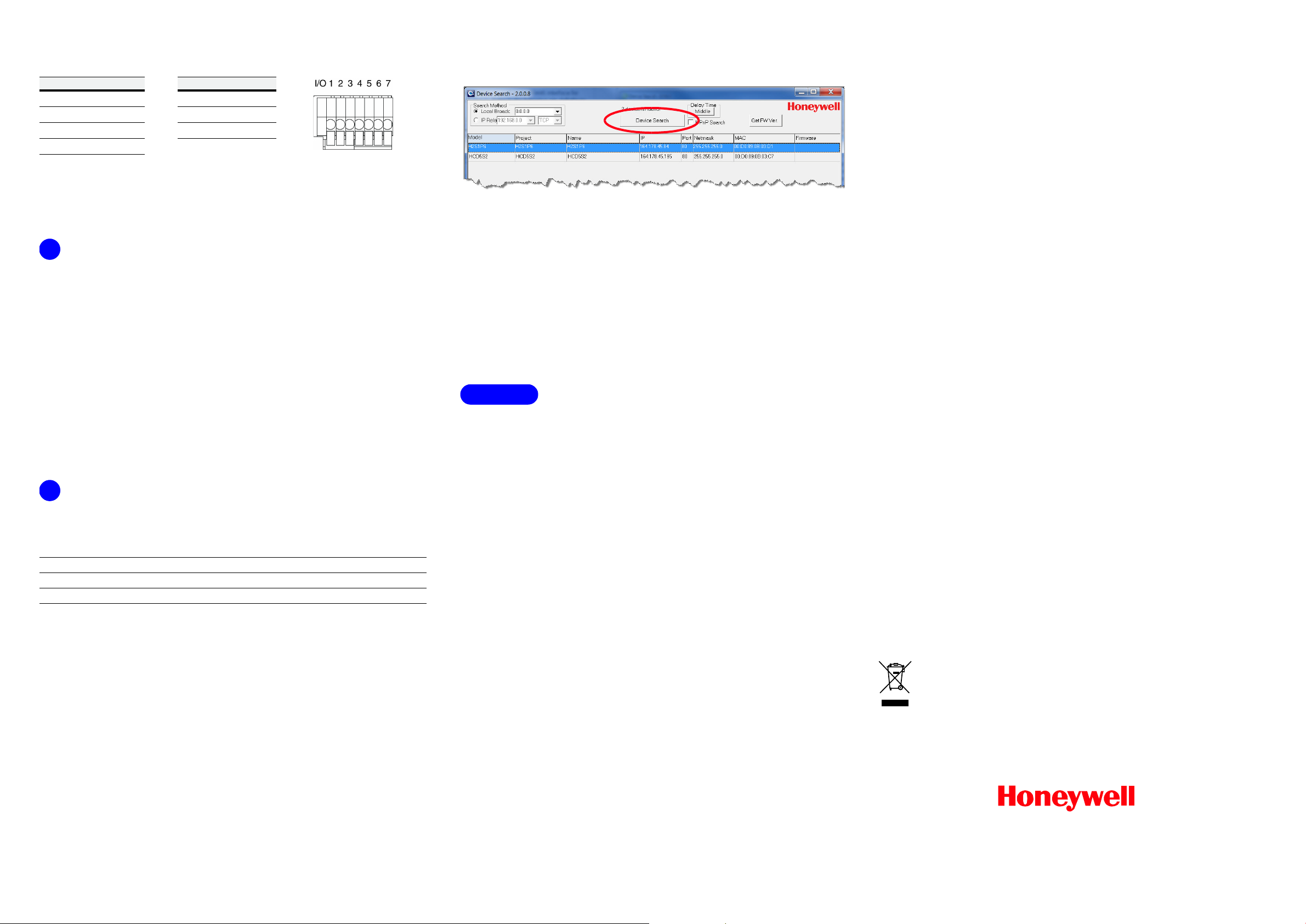
3. Double-click the Honeywell Device Search icon to run the application on your PC.
4. Click Device Search to find the camera with the Honeywell Device Search tool. By default, the
camera has a dynamically assigned IP address (DHCP). After finding the camera with the
Device Search tool, you can assign a static IP address to the camera, or otherwise modify the
network settings, as needed (refer to the equIP
the software and documentation CD for more information).
5. Double-click the discovered camera, or enter the camera’s IP address into the address bar of
your web browser.
6. In the Login dialog box, enter the default user name (admin) and password (1234) and then
click OK. The user name is case sensitive.
The first time you run the Honeywell Viewer web client, you will be prompted to install an
ActiveX plug-in. Follow the on-screen instructions to install the plug-in. Once the plug-in has
been installed, the web client opens automatically in your browser, displaying live video and
basic controls. Refer to the equIP
and documentation CD for more information on using the Honeywell Viewer web client.
®
Series IP Cameras Configuration Guide on the software
®
Series IP Cameras Configuration Guide on
Clip Storage on MicroSDHC Card
Preparing to Use the MicroSDHC Card
Install the microSDHC card in the card slot before you finish installing the camera (see Completing
the Installation). Log on to the camera with the web client (see Logging In to the Camera, above).
Note If needed, you can format the microSDHC card to erase the contents (System
Management
automatic deleting of old clips from the microSDHC card with the Disk cleanup setting.
Note To record audio with the video, enable that option in Streaming
SD Card Device setting, and click Format). You can also set up
Audio.
Configuring MicroSDHC Card Recording
Set up recording(s) to the microSDHC card (types of recording available include: Continuous,
Scheduled, Alarm Triggered, Motion Triggered, Network Failure Triggered, and Tampering
Triggered recording). Set up the recording parameters, as needed. Select the SD Card in either the
Record To or Recording Storage option when configuring the selected recording type.
Note For more information on Alarms, Events, and Recording settings, refer to the equIP Series
IP Cameras Configuration Guide included on the software and documentation CD.
Downloading and Playing Clips Recorded to a MicroSDHC Card
1. Go to System Storage Management SD Card. The list of video clips (in AVI format) is
in the Recording list section at the bottom of the page.
Note If needed, you can click Sort to change the order that the video clips are sorted in (can be
sorted by date or recording type).
2. Select a clip from the list and click download.
3. You can choose to either Open or Save the file. Select Open to immediately play the clip with
your default video player after it has downloaded. Select Save to save the file to a location on
your hard drive. Once saved you can use the file as needed (distribute and/or play the clip).
Storage
Deleting Clips from a MicroSDHC Card
There are three options for deleting video clips from a microSDHC card:
• Format the card, deleting all clips from the microSDHC card
SD Card Device setting, and click Format)
•Set up
• Remove the clips, one at a time
automatic disk cleanup
specified capacity
list; select one or more clips from the recording list and click Remove).
(System Storage Management SD Card Disk cleanup setting)
, to delete clips of a certain age when the card storage reaches a
(System Storage Management SD Card Recording
(System Storage Management
.
Regulatory Statements
FCC Statement of Compliance
Information to the User: This equipment has been tested and found to comply with the limits for a
Class A digital device, pursuant to part 15 of the FCC Rules. These limits are designed to provide
reasonable protection against harmful interference when the equipment is operated in a commercial
environment. This equipment generates, uses, and can radiate radio frequency energy and, if not
installed and used in accordance with the instruction manual, may cause harmful interference to
radio communications. Operation of this equipment in a residential area is likely to cause harmful
interference in which case the user will be required to correct the interference at his own expense.
Note Changes or modifications not expressly approved by the party responsible for compliance
could void the user’s authority to operate the equipment.
This Class A digital apparatus complies with Canadian ICES-003.
Cet appareil numérique de la Classe A est conforme à la norme NMB-003 du Canada.
Manufacturer’s Declaration of Conformance
North America The equipment supplied with this guide conforms to UL 60950-1 and CSA C22.2
No. 60950-1.
Europe The manufacturer declares that the equipment supplied with this guide is compliant with
the European Parliament and Council Directive on the Restrictions of the use of certain hazardous
substances in electrical and electronic equipment (2011/65/EU), General Product Safety Directive
(2001/95/EC), and the essential requirements of the EMC Directive (2004/108/EC), conforming to the
requirements of standards EN 55022 for emissions, EN 50130-4 for immunity, and EN 60950-1 for
electrical equipment safety.
CAUTION This is a Class A product. In a domestic environment this
product may cause radio interference in which case the user may be required
to take adequate measures.
WARNING
employed when powering the camera from 24 V AC.
Waste Electrical and Electronic Equipment (WEEE)
Correct Disposal of this Product (applicable in the European Union and other
European countries with separate collection systems).
This product should be disposed of, at the end of its useful life, as per applicable local
laws, regulations, and procedures.
To comply with EN50130-4 requirements, a UPS should be
.
© 2014 Honeywell International Inc. All rights reserved. No part of this publication may be reproduced by any means without written permission from Honeywell. The information in this publication is believed to be accurate in all respects.
However, Honeywell cannot assume responsibility for any consequences resulting from the use thereof. The information contained herein is subject to change without notice. Revisions or new editions to this publication may be issued to
incorporate such changes.
www.honeywell.com/security
+1 800 323 4576 (North America only)
https://www.honeywellsystems.com/ss/techsupp/index.html
Document 800-15466V3 – Rev A – 01/2014
 Loading...