

Page 1

HCE 80/HCE 80R
Underfloor Heating
Controller
Installation and Operation
Zoneregelaar
Montage en gebruik
HCC 80/HCC 80R
Page 2

Page 3

ENGLISH 3
NEDERLANDS 17
Page 4

1x
8x
8x
1x
1x
1x
1x
Fig.1
Fig.2
B+ H/C TW
HRA80
MCR
Panther
Swite
9 10
Power
12
1
2
14
2 3 4 51
Mode
345678
3
4
5
6
Z3Z1 Z2 Z4 Z5 Z6 Z7 Z8
Fig.3
7
8
678
11
Fig.4
13
12
L
N
PE
L
L
PE
5.5mm
5.5mm
Fig.5 Fig.6 Fig.7
7mm
Page 5

Contents
1. About these instructions ........................................ 4
2. General safety instructions.................................... 4
3. Overview ............................................................... 4
3.1. Differences between the individual device types ... 5
3.2. Function overview ................................................. 5
4. Creating a zoning plan .......................................... 5
4.1. Specifying temperature zones ............................... 5
4.1.1. Example of zone divisions..................................... 5
5. Installation ............................................................. 5
5.1. Wall installation ..................................................... 6
5.2. DIN rail installation ................................................ 6
5.3. Installing components............................................ 6
6. Installation and configuration................................. 6
6.1. Opening the housing ............................................. 6
6.1.1. Plugging in the expansion module (optional)......... 6
6.1.2. Setting the thermal actuator type........................... 6
6.2. Cabling connections .............................................. 6
6.2.1. Permissible cable types and lengths ..................... 6
6.2.2. Connecting power cable........................................ 7
6.2.3. Connecting the thermal actuators.......................... 7
6.3. Boiler feedback...................................................... 7
6.3.1. Connecting the boiler feedback via an analog
output (only HCE 80/ HCC 80) to external
controllers.............................................................. 7
6.3.2. Implementing a boiler feedback via a wireless
connection (with HC60NG/R6660D)...................... 8
6.3.3. Implementing a boiler feedback with an
integrated relay 42 V AC, floating contact (only
HCE 80R/HCC 80R).............................................. 8
6.4. Pump..................................................................... 8
6.4.1. Pump control ......................................................... 8
6.4.2. Connecting a pump (230 V AC)............................. 8
6.4.3. Installing an external antenna................................ 8
6.4.4. Closing the housing of the underfloor heating
controller ............................................................... 8
7. Commissioning...................................................... 8
7.1.1. Commissioning the underfloor heating controller .. 8
7.2. LED indicators on underfloor heating controller..... 9
7.3. Checking the signal strength of the radio
transmission .......................................................... 9
7.4. Operating modes of the Underfloor Heating
controller ............................................................... 9
7.4.1. Normal mode......................................................... 9
7.4.2. Fault mode ............................................................ 9
7.4.3. Installation mode ................................................... 9
7.4.4. Device display ....................................................... 9
7.5. Cooling function..................................................... 9
7.5.1. Activating the cooling function............................... 9
7.5.2. Switching between heating and cooling ................ 9
7.5.3. Assigning room names.......................................... 9
8. Assigning zones and allocating room names
(teach-in) ............................................................... 9
8.1. Allocating the setpoint adjuster HCW 82, room
temperature sensor HCF 82.................................. 9
8.2. Allocating Hometronic Manager HCM 200D........ 10
8.3. Assigning the room control system CM67z ......... 10
8.3.1. Teach-in room temperature sensor ..................... 10
8.3.2. Teach-in time program CM67z (Zone 1)............. 10
8.3.3. Teach-in time program CM67z (Zone 2)............. 10
8.4. Time program for cooling function ....................... 11
8.5. Allocating relay modules for controlling the heat
generator ............................................................. 11
8.5.1. Teach-in for boiler feedback HC60NG/R6660D .. 11
8.6. Cancelling the assignment .................................. 11
8.6.1. Cancelling the assignment of the setpoint
adjuster to a temperature zone............................ 11
8.6.2. Cancelling assignment of the room name or
time program to the temperature zone ................ 11
8.7. Saving the settings on the Hometronic Manager . 11
9. Checking the configuration .................................. 11
9.1. Checking radio transmission ............................... 11
9.1.1. Sending test signals ............................................ 11
9.1.2. Receiving test signals.......................................... 11
10. Displaying faults ..................................................12
11. Completing commissioning.................................. 12
11.1. Note to installer.................................................... 12
11.2. Resetting underfloor heating controller to state
of delivery ............................................................ 12
12. Changing the fuse ............................................... 12
13. Appendix ............................................................. 12
13.1. Glossary .............................................................. 12
13.2. Help with problems.............................................. 13
13.3. Technical data ..................................................... 13
13.4. Device and function definition in accordance
with EN 60730-1.................................................. 13
13.5. Zoning plan (sample)........................................... 14
13.6. WEEE directive 2002/96/EC Waste Electrical
and Electronic Equipment directive .....................14
13.7. Brief instructions.................................................. 15
13.7.1. Navigation and function overview ........................ 15
Contents
3
Page 6
About these instructions
1. About these instructions
Fold out the left-hand cover. This shows all the operating
elements and connections. Leave the cover folded out while
reading further.
Technical terms are explained in the glossary (Page 12).
Legend for fold-out page
Fig. 1 Scope of delivery
Fig. 2 Opening housing
Fig. 3 Display and operating elements
Number Labelling Function
(1)
(2)
(3)
(4)
(5)
(6)
Power
Mode
Power supply on/off
Information display
Installation display
Operating mode button
Installation button
Pump on/off display
(7) 1...8 Zone LEDs
(8) Labelling of Zones 1...8
Fig. 4 Connections
Number Function
(9) I/O connector
(10) Switch for setting normally open/normally closed
(11) Slot for expansion module HCS 80
(12) Connector for supply voltage, pump
(13) Fuse
(14) Slot for internal antenna
(Z1 - Z8) Connector for Zones 1...8
Fig. 5 I/O connector
Fig. 6 Connector for Zones 1...8
Fig. 7 Connector for supply voltage, pump
2. General safety instructions
DANGER
WARNING
Danger to life through electric
shock!
Contacts that are open are live.
► Unplug the power plug before open-
ing the housing.
,
► Have all the work carried out by
authorised specialist personnel.
► Observe the valid VDE regulations
during the installation.
Damage to the underfloor heating
controller!
Short-circuiting through humidity and
moisture.
► Mount the device at a site that is
protected against humidity and moisture.
3. Overview
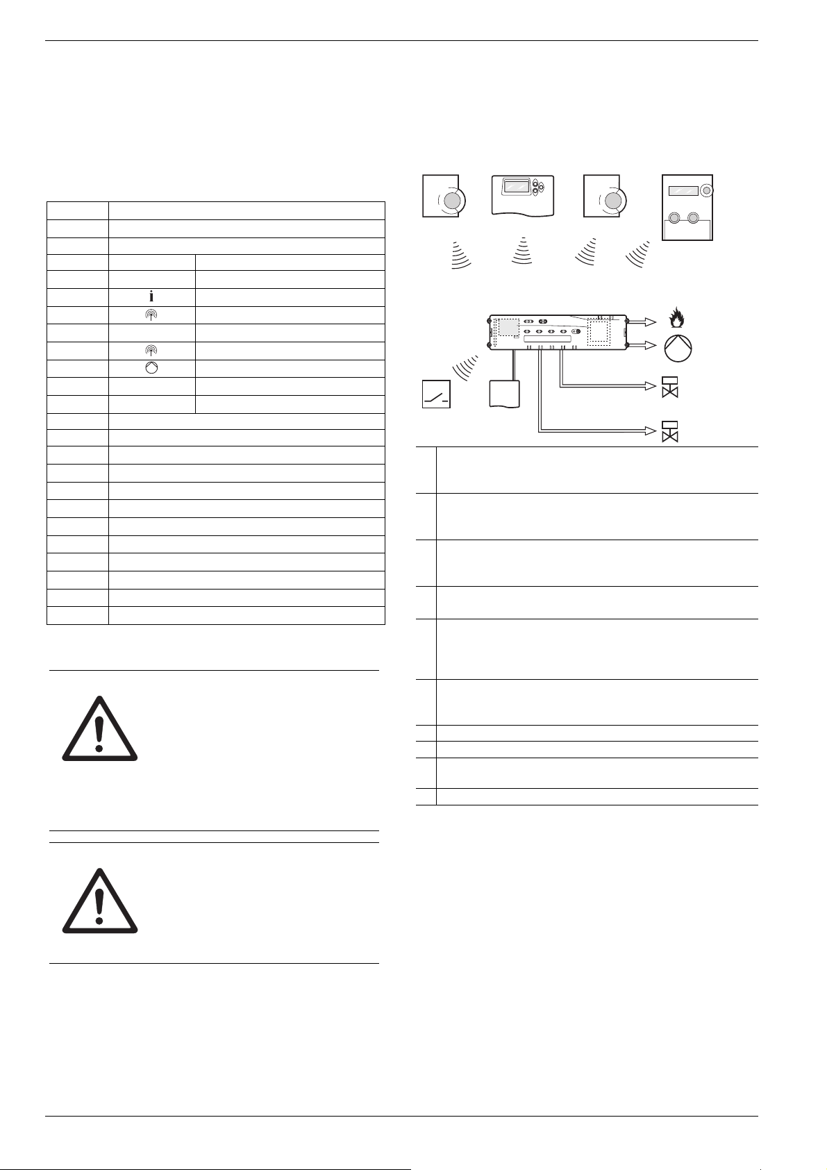
The floor hearing system is an intelligent system for individual room temperature control. The following overview shows
devices that can operate together with the underfloor heating controller.
(B)
(E)
(I)
(J)
(I)
A Setpoint adjuster HCW 82
Controls the setpoint temperature for each temperature
zone via adjustment dial
B Central operating device CM67z
Controls the room temperature via programmable time
programs
C Room temperature sensor HCF 82
Transmits room temperature information to underfloor
heating controller
D Hometronic Manager HCM 200D
Central operating unit of the house-automation system
E Underfloor heating controller
HCE 80/HCC 80/HCE 80R/HCC 80R
Controls actuators; communicates with setpoint adjusters
and room temperature sensors
F Boiler feedback,
Analog output (only HCE 80/HCC 80) or
Relay output (only HCE 80R/HCC 80R)
G Integrated pump relay
H Thermal actuators
I External antenna HCE 80/HCE 80R
Internal antenna HCC 80/HCC 80R
J Boiler feedback relay HC60NG/R6660D
(C)(A)
(D)
(F)
(G)
(H)
4
Page 7

Creating a zoning plan
3.1. Differences between the individual
HCE 80 HCE 80R HCC 80 HCC 80R
Antenna
Pump
relay
Analog
output
Boiler
feedback
radio
Boiler
feedback
relay
device types
External External Internal Internal
230 V AC
internal
Exists Does not
External
with
HC60NG/
R6660D
Does not
exist
The pump relay 230 V AC is not floating.
230 V AC
internal
exist
External
with
HC60NG/
R6660D
42 V AC/DC Does not
230 V AC
internal
Exists Does not
External
with
HC60NG/
R6660D
exist
230 V AC
internal
exist
External
with
HC60NG/
R6660D
42 V AC/DC
3.2. Function overview
• 5 controllable temperature zones, extendable to 8
• Up to 3 thermal actuators can be connected per zone
• Normally open and normally closed thermal actuators
can be used
• Integrated pump relay
• Boiler feedback
– Analog (only HCE 80/HCC 80)
– Integrated relay with floating contact 42 V AC/DC
(only at HCE 80R/HCC 80R)
– Wireless via relay HC60NG/R6660D
• Underfloor heating controller can be switched between
heating and cooling
• 1 antenna can be used for 3 controllers
• Internal or external antenna can be used
• Rapid mounting by screwless terminals of the thermal
actuators
• Intelligent controlling via fuzzy logic
• Simple diagnosis of the wireless transmission
• Operating state display via LEDs
4. Creating a zoning plan
Within a building rooms (zones) can be controlled with different room setpoint temperatures. The thermal actuators of
the allocated zone (room) are controlled depending on the
room setpoint temperature.
A maximum of 5 temperature zones can be set
for each underfloor heating controller. This number can be increased to 8 by using the expansion
module HCS 80.
A maximum of 3 actuators can be connected in
Temperature zones
(maximum)
8 24 1
16 48 2
24 72 3
Tab. 1: Overview of temperature zones/ underfloor heating controllers
each zone.
Actuators
(maximum)
No. of underfloor
heating controllers
4.1. Specifying temperature zones
► Specify the number of zones and corresponding rooms.
► Allocate the corresponding room device, for example
HCW 82, CM67z, and the required thermal actuators to
each zone.
► Label the room devices and thermal drives for the respec-
tive zone (refer to the fold-out page Fig. 4, Z1...Z8).
4.1.1. Example of zone divisions
kitchen
hall
dining room
living room
bathroom
Explanation of this example:
• The living area is covered by six temperature zones. The
additional module HCS 80 is required for this partitioning.
• The underfloor heating controller controls 8 actuators.
bedroom
toilet
5. Installation
WARNING Insufficient data transfer!
Interference of the radio receiver in the
device through metallic objects and
further radio devices.
► When selecting the operating site
ensure that the distance to radio devices such as radio headphones,
cordless phones, etc. according to
the DECT standard amounts to at
least 1 m.
► Ensure that there is sufficient dis-
tance to metallic objects.
► Select another installation site if the
WARNING
The underfloor heating controller was designed for installation in a distributor box. If insufficient space is available,
select an area where the underfloor heating controller can
communicate with the setpoint adjusters by radio without
interference and that is protected from moisture and water.
The underfloor heating controller can be installed in one of 2
ways:
• Wall installation
• DIN rail installation
radio interference cannot be rectified.
Damage to the underfloor heating
controller!
Short-circuiting through humidity and
moisture.
► Mount the device at a site that is
protected against humidity and moisture.
5
Page 8

Installation and configuration
5.1. Wall installation
Four 4.2 mm holes for installation are located on the underfloor heating controller.
Take the 52 mm installation height of the underfloor heating controller into account. If the underfloor heating controller is installed at a severe
angle, the transformer must be on top to allow for
ventilation.
57
52.0
337
∅
4.2
349.5
Dimensions of underfloor heating controller in mm
► Mark, drill and insert plugs into fastening holes.
► Screw on the underfloor heating controller.
5.2. DIN rail installation
► Place the housing on the DIN
rail from below (1).
► Press the housing upwards
until it snaps into place (2).
5.3. Installing components
Install the components as described in the accompanying
installation instructions.
6. Installation and configuration
DANGER
WARNING Damage to exposed components!
Danger to life through electric
shock!
Contacts that are open are live.
► Unplug the power plug before open-
ing the housing.
► Have all the work carried out by
authorised specialist personnel.
► All wiring must be in accordance with
IEE & Building Regulations.
Destruction of the electronic components through electrostatic discharges.
► Do not touch the components.
► Touch an earthed piece of metal to
discharge static electricity from your
body.
85
6.1. Opening the housing
► Open the housing as shown in Fig. 2 on the fold-out page.
6.1.1. Plugging in the expansion module
(optional)
The expansion module HCS 80 expands the number of
possible temperature zones of the underfloor heating controller from 5 through 8.
► Insert the expansion
module with the adapter
connector into the provided slot.
6.1.2. Setting the thermal actuator type
Only one thermal actuator type can be connected
per underfloor heating controller. If normally open
and normally closed actuators are to be operated, you require two underfloor heating control-
► Check the type of thermal actuator being used.
► Set the switches in accordance with the following table
Switch
position
lers.
The thermal actuators are protected by a ceramic
fuse.
(see the fold-out page, Fig. 4 (10)):
Thermal actuator type
Normally closed
Normally open
Property
Opens the heating circuit if
power is present at its control
input
Opens the heating circuit if
power is not present at its
control input
6.2. Cabling connections
6.2.1. Permissible cable types and lengths
Thermal actuators
Outer cable diameter
Cable length Max. 400 m
Cable cross-section Max. 1.0 mm²
Stripping length 4 mm
Terminal range of
the connectors
Power and pump connection 230 V AC
Outer cable diameter
Cable length Max. 100 m
Cable cross-section Max. 1.5 mm²
Stripping length 7 mm
Terminal range of
the connectors
Min. 3.5 mm/Max. 5.3 mm
0.07–1.33 mm²; flexible wire
Min. 8.0 mm/Max. 11 mm
0.50–2.50 mm²; flexible/fixed connection
0.50–1.50 mm²; flexible, with wire end
ferrule
6
Page 9

Installation and configuration
Antenna connection
Cable length Max. 30 m
Cable cross-section
JE-LiYCY 2x2x0.5 mm²;
JE-Y(St)Y ∅2x2x0.8 mm;
2x0.5 mm²
Stripping length 5.5 mm
Terminal range of
0.07–1.54 mm²
the connectors
Heating/cooling, boiler feedback
Cable length Max. 100 m
Cable cross-section
JE-LiYCY 2x2x0.5 mm²;
JE-Y(St)Y ∅2x2x0.8 mm;
2x0.5 mm²
Stripping length 5.5 mm
Terminal range of
0.07–1.54 mm²
the connectors
Tab. 2: Permissible cable types and lengths
6.2.2. Connecting power cable
DANGER
► Select a suitable cable in accordance with Table 2 for the
power supply.
► Strip the connections 7 mm (see fold-out page, Fig. 7).
Danger to life through electric
shock!
Contacts that are open are live.
► Ensure that the cable is deenergized.
► Lay the actuator cables to the distribution box.
► Connect the actuator wires.
► Break out the openings for
the cables on the housing
using a diagonal cutter.
► Strip the connections 5.5 mm (see
fold-out page, Fig. 6).
► Insert the connecting cables of the
actuators into the cable openings of
the connectors.
► Close the terminators.
► Plug the connectors into the sockets of the corresponding
zones (see the fold-out page, Fig. 4 (Z1 -Z8)).
► Clamp the cables into the stress relief clamp.
► Secure the cable with the cable clamp.
Installation Disassembling
► Connect the cable to the connector in
accordance with the graphics (see
L
fold-out page, Fig. 4 (12)).
► Plug the connector into Socket 12
(see the fold-out page, Fig. 4).
► Secure the cable with the cable clamp.
Installation Disassembling
6.2.3. Connecting the thermal actuators
WARNING
Damage to the underfloor heating
controller!
► Take the technical data into account
at thermal actuators: Total of 3 A
maximum current, 250 mA continuous current per zone.
Each zone can control up to 3 actuators. 3 actuators can be
connected directly for zone 1, 2 for zone 2 and 1 each for
zones 3 through 5. One connection for the expansion module is available for each of the zones 6 through 8.
If more than 11 thermal actuators are to be connected to the
underfloor heating controller, the cables of the actuator must
be wired in a distribution box.
6.3. Boiler feedback
6.3.1. Connecting the boiler feedback via
an analog output (only HCE 80/
HCC 80) to external controllers
The analog output voltage changes depending on the valve
position.
► Strip the connections 5.5 mm (see fold-out page, Fig. 5).
► Connect the boiler feedback
in accordance with the following graphics (see the
fold-out page, Fig. 4 (9)).
Boiler feedback is possible with the controllers MCR 200,
MCR 40, ZG 252 N, Panther and Smile.
► Connect the controller inputs in accordance with the en-
closed instructions (earth input to Terminal 6, temperature
input to Terminal 5 of the underfloor heating controller).
TW
H/C
B+
7
Page 10
Commissioning
A
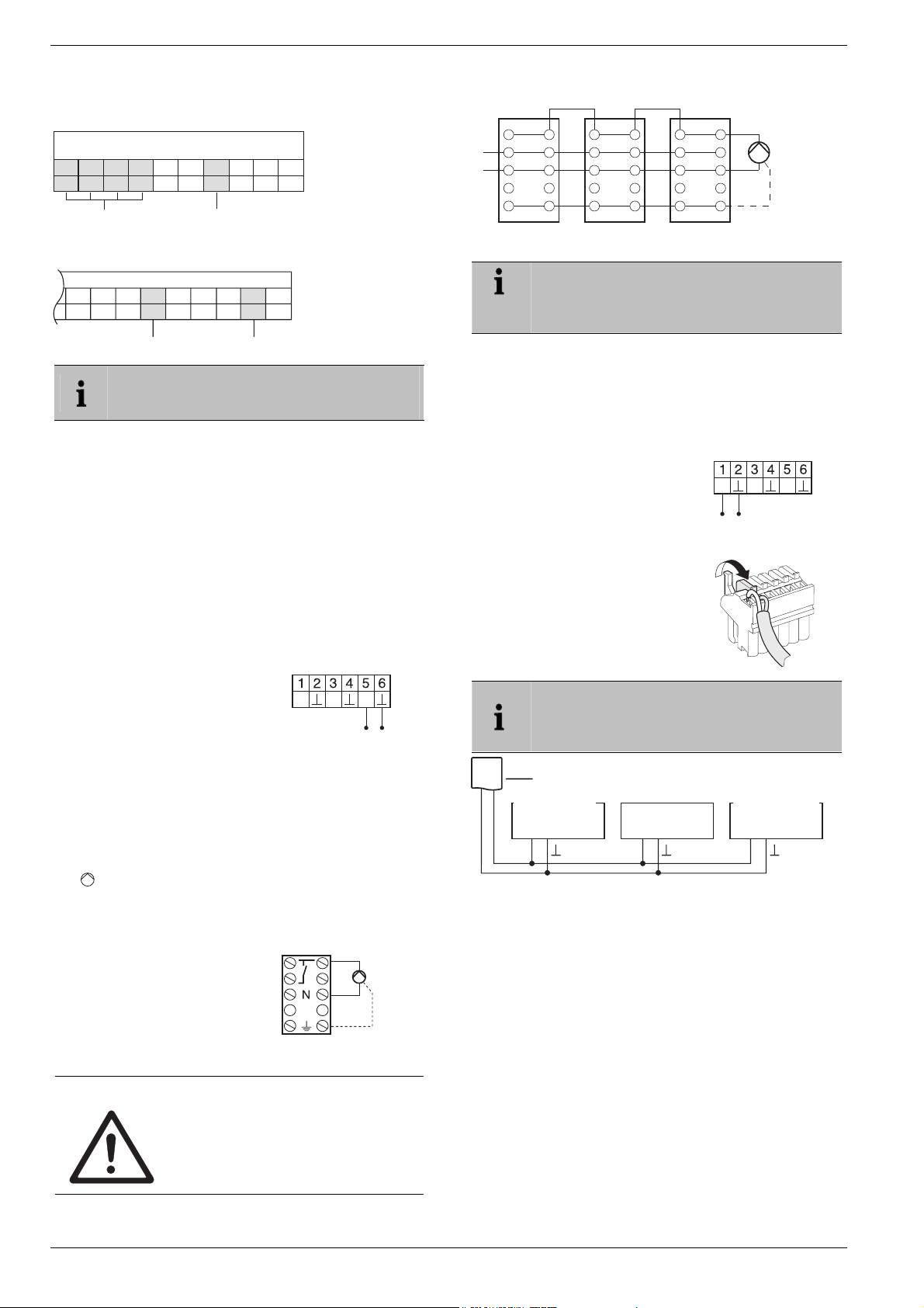
With controller MCR 40, the temperature and earth inputs
are located at the following terminals:
Earth input
MCR 40
Low-voltage side
Temperature input
TW
78910456123
With controller ZG 252 N, the temperature and earth inputs
are located at the following terminals:
ZG 252 N
456 10
789 1112
Earth input
TW
Temperature input
Depending on the design, the temperature selector and earth inputs are found on different terminals of the controller MCR 200.
6.3.2. Implementing a boiler feedback via
a wireless connection (with
HC60NG/R6660D)
The relay is switched on and off depending on the valve
setting.
6.3.3. Implementing a boiler feedback with
an integrated relay 42 V AC, floating
contact (only HCE 80R/HCC 80R)
The relay is switched on and off depending on the valve
setting.
► Strip the connections 5.5 mm (see fold-out page, Fig. 5).
► Connect the boiler feedback
in accordance with the following graphics (see the fold-out
page, Fig. 4 (9)).
B+
H/C
TW
6.4. Pump
6.4.1. Pump control
As soon as a zone is active, the pump is activated with a
time delay. The pump switches off as soon as all the valves
are closed.
LED (see fold-out page, Fig. 3 (6)) lights up green
The
when the pump is running.
6.4.2. Connecting a pump (230 V AC)
► Strip the connections 7 mm
(see fold-out page, Fig. 7).
► Connect the pump in accor-
dance with the following
graphics (see the fold-out
page, Fig. 4 (12)).
WARNING
Damage to the underfloor heating
controller!
Short-circuit due to incorrect installation.
► Connect all the controllers to the
same phase.
L
Pump
PE
Controller 1
L
N
PE
6.4.3. Installing an external antenna
Controller 2 Controller 3
Pump
N
PE
Up to three underfloor heating controllers can be
connected to an antenna. When selecting the
operating site ensure that the function of the
antenna is not impaired.
► Only install the external antenna outside metal housings
(e.g. control cabinets).
► Install the antenna at a suitable location near the under-
floor heating controller. Ensure that a radio connection to
the setpoint adjuster exists.
► Strip the connections 5.5 mm (see fold-out page, Fig. 5).
► Connect the antenna in accor-
dance with the following graphics
(see the fold-out page, Fig. 4 (9)).
B+ H/C
TW
Shield to 2
Second conductor to 1
► Close the terminals.
If several underfloor heating controllers are operated simultaneously, an antenna (internal or
external) may only be connected to one controller.
ntenna
Controller 1
Regler 1 Regler 2 Regler 3
Controller 2
Controller 3
B+ B+ B+
6.4.4. Closing the housing of the underfloor heating controller
► Place the housing cover back on (see fold-out page).
► Snap the left and right snap lock back into place.
► Tighten the screws on the top.
7. Commissioning
During commissioning, setpoint adjusters – and the time
programs of the radio setpoint adjuster CM67z if applicable
– are assigned to the temperature zones of the underfloor
heating controller. A room name is defined for each temperature zone at the Hometronic Manager.
7.1.1. Commissioning the underfloor heating controller
► Switch on the operating voltage.
The mains voltage LED (POWER) lights up.
8
Page 11

Assigning zones and allocating room names (teach-in)
7.2. LED indicators on underfloor heating controller
The LEDs on the underfloor heating controller indicate the
operating mode of the Underfloor Heating controller and the
installed temperature zones.
Meaning of the 3 LEDs (see fold-out page, Fig. 3 (1,2,3)):
LED Display Meaning
POWER (green) Lights up Normal mode
(red)
Flashing Antenna fault display
(yellow)
Lights up Group alarm
Rapid
flashing
No device installed
7.3. Checking the signal strength of the
radio transmission
The signal strength of the radio transmission can be
checked for the transmitter and the receiver. Refer to Section "Checking radio transmission
" on Page 11.
7.4. Operating modes of the Underfloor
Heating controller
7.4.1. Normal mode
In normal mode the LEDs 1...8 show the position of the
actuators, see Fig. 3 (7) on the fold-out page:
Green Thermal drive opened
Off Thermal drive closed
7.4.2. Fault mode
The various faults are indicated by the zone LEDs in fault
mode. Refer to Section "Displaying faults" on Page 12.
7.4.3. Installation mode
In installation mode temperature zones are assigned to
the setpoint adjusters and the Hometronic Manager. Refer to Section "Assigning zones and allocating room
names (teach-in)" on Page 9.
7.4.4. Device display
The device display shows which devices are assigned to
the underfloor heating controller. Refer to Section
"Checking the configuration" on Page 11.
7.5. Cooling function
If the underfloor heating controller is used as a cooling regulator, this function has to be activated once during installation.
7.5.1. Activating the cooling function
► Keep the Mode button pressed for at least 4 seconds.
LED shows whether heating or cooling mode is
The
activated:
LED lights up green
LED lights up red
► Change the setting by pressing the installation button .
Cooling mode active
Heating mode active
The underfloor heating controller switches back
to normal mode automatically after 60 seconds.
You can also exit the installation mode by pressing the Mode button.
7.5.2. Switching between heating and
cooling
Switching between heating and cooling is carried
out via the changeover contacts 3 and 4.
► In order to activate the cool-
ing function connect the
changeover contacts 3
and 4, (see fold-out page,
Fig. 4 (9)), e.g. through an
external switch.
B+ H/C
External switch
TW
7.5.3. Assigning room names
► Enter the room names in the zoning plan.
► Press the installation button
flashes.
The LED of zone 1 flashes red.
► Allocate the setpoint adjuster.
► Press the installation button
The LED of zone 1 flashes green.
► Allocate a time program for Heating.
► Press the installation button .
The LED of zone 1 flashes yellow.
► Allocate a time program for Cooling.
Repeat the steps until two room names are assigned to all
the temperature zones.
until the LED of Zone 1
.
8. Assigning zones and allocat-
ing room names (teach-in)
The following section explains how you can assign the various components to a temperature zone and allocate room
names if a Hometronic Manager is used.
Only one setpoint adjuster can be assigned to a
temperature zone. If a room temperature sensor
HCF 82 is combined with a remote setpoint adjuster HCW 82, i.e. assigned to the same zone,
first assign the remote setpoint adjuster and then
the room temperature sensor.
If the installation button at the underfloor heating controller is not pressed for 4 minutes, the
underfloor heating controller reverts automatically
8.1. Allocating the setpoint adjuster
In the following example the setpoint adjuster HCW 82 is
assigned to Zone 1. Subsequently the room name "Living" is
assigned to Zone 1 in the time program of the Hometronic
Manager.
► Keep the zoning plan at hand.
► Keep the installation button
to normal mode.
HCW 82, room temperature sensor
HCF 82
at the underfloor heating
controller pressed for 2 seconds.
LED lights up. The LED of Zone 1 flashes red.
The
9
Page 12

Assigning zones and allocating room names (teach-in)
The underfloor heating controller is in installation mode
and waits for the signal from the setpoint adjuster.
In order to assign the setpoint adjuster to a different zone, press the installation button until
the LED of the desired zone flashes red.
► Press the Send button of the setpoint adjuster.
The setpoint adjuster is assigned to Zone 1.
The LED of the selected zone lights continuously red.
If no time program is active, the underfloor heating controller operates with a basic value of 20°C
(heating mode) or 26°C (cooling mode). Please
refer to Page 11 for information about checking
the configuration.
8.2. Allocating Hometronic Manager
► Press the installation button at the underfloor heating
► Select the desired room name, e.g. LIVING, in the Settings
► Press the Input button.
► Enter the room name in the zoning plan.
► Repeat the steps until a room name is assigned to all the
► Press the installation button
The underfloor heating controller is back in normal mode.
HCM 200D
For information on installing the device please
read the HCM 200D operating instructions.
controller again.
The LED of the selected zone flashes green. The underfloor heating controller waits for a signal from the
Hometronic Manager.
> Installation > Heating/Cooling menu
LIVING *
A * appears after "LIVING".
The LED on the underfloor heating controller in Zone 1
lights up green. The name "LIVING" has been assigned
to temperature zone 1.
temperature zones.
guishes.
If the installation button is not pressed for 4 minutes, the underfloor heating controller reverts to
normal mode.
The assigned temperature zones remain stored
in the underfloor heating controller, even after a
power failure.
DINING
KITCHEN
BEDROOM
until the LED extin-
8.3. Assigning the room control system
CM67z
8.3.1. Teach-in room temperature sensor
For information on installing the device please
read the CM67z operating instructions.
The CM67z operating unit has an integrated temperature
sensor for Zone 1. The function of the sensor is specified by
parameter 7:tS in the installation mode:
► Set parameter 7:tS to the setting "2".
► Set parameter 17:SU to the setting 0 (only HR 80) or 2
(HR 80 and R6660D).
The integrated sensor is now used to measure and control the room temperature in Zone 1.
10
Information about the parameter settings of the
CM67z can be found in the corresponding operating instructions.
► Move the slide switch at the operating unit CM67z to the
position OFF. Move the buttons TEMP
, TEMP and
PROG 1 together in order to activate the teach-in mode
for Zone 1.
The following is displayed at the
CM67z:
► Keep the installation button at the underfloor heating
controller pressed for 2 seconds.
LED lights up. The LED of Zone 1 flashes red.
The
The underfloor heating controller is in installation mode
and waits for the signal from the CM67z.
In order to assign the CM67z to a different zone,
press the installation button until the LED of
the desired zone flashes red.
► Send the teach-in signal by pressing the button .
8.3.2. Teach-in time program CM67z
(Zone 1)
► Press the installation button at the underfloor heating
controller again.
The LED of zone 1 flashes green.
► Send the teach-in-signal by pressing the button .
The LED of the selected zone lights continuously green.
8.3.3. Teach-in time program CM67z
(Zone 2)
No internal sensor is available at CM67z for Zone
2. You have to assign an external sensor
(HCF 82) to the zone (see Allocating the setpoint
adjuster HCW 82, room temperature sensor
► Move the slide switch at the operating unit CM67z to the
► Press the button MAN
► Press the installation button at the underfloor heating
► Send the teach-in-signal by pressing the button .
HCF 82, chapter 8.1).
position OFF. Move the buttons TEMP
, TEMP and
PROG 1 together in order to activate the teach-in mode
for Zone 1.
in order to switch the operating
unit CM67z to the teach-in mode for Zone 2.
The following is displayed at the
CM67z:
controller again briefly.
LED lights up. The LED of the selected zone
The
flashes green.
The underfloor heating controller is in installation mode
and waits for the signal from the CM67z.
In order to assign the CM67z to a different zone,
press the installation button until the LED of
the desired zone flashes green.
The LED of the selected zone lights continuously green.
Page 13

Checking the configuration
8.4. Time program for cooling function
If the cooling function was activated (see "Cooling function",
Page 9), a separate time program for heating and cooling
can be assigned for each zone (e.g. "Heat living", "Cool
living").
The time programs and setpoint values are activated by the
heating or cooling switchover contact.
The time program for heating is active when the connection
at terminal 3 and 4 is open at connector 9 (see fold-out
page, Fig. 4 (9)).
If terminals 3 and 4 are connected, time cooling time program becomes active.
If no time program for cooling is assigned to a
zone, the standard room setpoint temperature is
26°C.
8.5. Allocating relay modules for controlling the heat generator
Depending on the heat requirement of the installed rooms
the relay module HC60NG/R6660D controls the heat generator as a function of the valve setting.
8.5.1. Teach-in for boiler feedback
HC60NG/R6660D
► Press the button at the relay module HC60NG/R6660D for
5 seconds in order to activate the mode.
The red LED at the relay module flashes in the rhythm
0.5 sec on, 0.5 sec off.
► Press the installation button
controller briefly.
After successful allocation the red LED of the relay module extinguishes.
► Press the installation button
controller again when leaving the device display.
at the underfloor heating
at the underfloor heating
8.6. Cancelling the assignment
8.6.1. Cancelling the assignment of the
setpoint adjuster to a temperature
zone
► Keep the installation mode pressed for at least 2 sec-
onds in order to access the installation mode.
LED lights up. The LED of Zone 1 flashes red.
The
► Press the installation button
the zone to be removed flashes red.
► Press the Mode button for at least 4 seconds.
The LED of the selected zone extinguishes.
The assignment of the setpoint adjuster to the tempera-
ture zone has been cancelled.
8.6.2. Cancelling assignment of the room
name or time program to the temperature zone
► Keep the installation mode pressed for at least 2 sec-
onds in order to access the installation mode.
The LED
► Press the installation button
the zone to be removed flashes green.
► Press the Mode button for at least 4 seconds!
The LED of the selected zone extinguishes.
lights up. The LED of Zone 1 flashes red.
repeatedly until the LED of
repeatedly until the LED of
The assignment of the room name or the time program to
the temperature zone is cancelled.
8.7. Saving the settings on the Hometronic Manager
The settings at the Hometronic Manager have to be saved
before commissioning is completed.
See: Operating instructions of the Hometronic Manager,
"Adaptation" chapter.
9. Checking the configuration
► Press the installation button .
The LED flashes yellow.
The underfloor heating controller shows up in the device
display.
The colours of LEDs 1...8 always indicate the configuration
of the temperature zones.
Off No device installed
Red
Yellow
Green
► Press the installation button briefly again.
The colours of LEDs 1...8 indicate the assignment of the time
programs to the temperature zones.
Green Time program for cooling assigned
Red Time program for heating assigned
Yellow Time program for heating/cooling assigned
9.1. Checking radio transmission
9.1.1. Sending test signals
The underfloor heating controller can send a test signal to
all the allocated radio receivers in order to test the signal
strength.
► Keep the
You can exit the test mode by pressing any button. After 4
minutes the device changes automatically to normal mode.
9.1.2. Receiving test signals
► Send a test signal to the underfloor heating controller.
Room temperature sensor/setpoint adjuster is
installed
Time program, setpoint adjuster and room temperature sensor are installed
Hometronic Manager or radio setpoint adjuster
CM67z is installed
If the heating/cooling is enabled, information
about the current status can be called up.
Mode and buttons pressed simultaneously
for at least 4 seconds.
The
LED flashes green.
The underfloor heating controller sends a test signal
every 5 seconds to the allocated radio receivers. The
zone LEDs light up briefly during sending.
For information on sending a test signal to the
underfloor heating controller read the instructions
of the corresponding radio transmitter.
When a test signal is received, the LED flashes green.
The zone LED of the corresponding zone indicates the
strength of the received signal by flashing
(1=sufficient…5=strong).
11
Page 14

Displaying faults
10. Displaying faults
If the LED lights up, a fault exists in at least one temperature zone.
The colours of the zone LEDs 1...8 provide information on
the type of fault in the respective temperature zone:
Off No fault
Red
flashing
Yellow
flashing
No connection to the setpoint adjuster, room
temperature sensor
No connection to the setpoint adjuster and
Hometronic Manager HCM 200D or central
operating device CM67z
Green
flashing
No connection to the Hometronic Manager
HCM 200D or central operating device CM67z
The fault display extinguishes as soon as the fault has been
eliminated.
11. Completing commissioning
► Close the housing (see "Closing the housing of the under-
floor heating controller", Page 8).
► Hand over the completed zoning plan and the installation
instructions to the customer.
11.1. Note to installer
After the underfloor heating controller has been commissioned, inform your customer about the heating control
system.
► Explain the function and operation of all the components to
the customer.
► Point out particular features to the customer and ensure
that they are aware of the possibility of expanding their
system.
11.2. Resetting underfloor heating controller to state of delivery
All current assignments are lost if the underfloor
heating controller is reset to the state of delivery.
The underfloor heating controller retains its con-
► Keep the Mode and buttons at the underfloor heating
figuration after a power failure.
controller pressed simultaneously for at least 10 seconds.
After 4 seconds the controller changes over to
test mode Continue to keep the button pressed
until the LED flashes yellow.
The LED lights up yellow (flashes rapidly).
The underfloor heating controller is reset to the state of
delivery.
12. Changing the fuse
► Deenergize the device.
► Open the housing (see "Opening the housing", Page 6).
Only use ceramic fuses of the type 230 V AC;
2.5 A; fast; 5 x 20 mm.
► Remove the holder with the fuse
(Steps 1 to 3).
► Replace the fuse (4) by a new
one.
3
4
2
1
► Insert the holder again:
Inserting (1)
Turn to the right.
► Close the housing (see "Closing the housing of the under-
floor heating controller", Page 8).
13. Appendix
13.1. Glossary
Term Explanation
Boiler feedback
Heating circuit
Hometronic
Hometronic Manager
Integrated Pump
Relay
Room setpoint
temperature
Room temperature
sensor
Setpoint adjuster
Thermal actuator
Time program
The control of the heat generator is
dependent on the amount of heat required.
Totality of all the control and regulating
devices of a temperature zone.
Home automation system from Honeywell.
Central operating device of the Hometronic System.
Controls a pump that is connected to the
underfloor heating controller.
Room temperature that is to be reached.
Detects the room temperature and
transfers it to the underfloor heating
controller.
Detects the actual temperature, changes
the setpoint temperature. Installed in a
user-friendly location in each zone.
Opens and closes a heating circuit. Is
controlled by the underfloor heating
controller.
Pre-defined setpoints and switching
points adjustable at the Hometronic
Manager and at the CM67z.
12
Page 15

Appendix
13.2. Help with problems
Problem Cause/Solution
Power LED does
not light up when
the power is
switched on.
LEDs 1...8 of the
zones do not illuminate green continuously during startup.
LEDs 1...8 of the
zones do not illuminate red continuously during startup.
Rooms are not
heated/cooled.
The LED lights up
red after commissioning.
Room controlled
incorrectly.
The LED flashes
rapidly.
The LED flashes.
Mains voltage not connected.
► Check voltage of electrical outlet.
► Check fuse at underfloor heating
controller.
The room name is not assigned.
► Check whether or not the Hometronic
Manager is installed.
► Check whether or not a room name is
assigned to zone.
► Check the antenna connection.
► Reassign the zone, if applicable.
The setpoint adjuster cannot be assigned.
► Check whether or not batteries in
setpoint adjuster are inserted properly.
► Check wireless connection.
► Check the antenna connection.
► Check heating and inlet temperature.
► Check adaptation to thermal actuator
(see Page 6).
► Check fuse of underfloor heating
controller.
If fuse is defective:
► Check actuators for short circuit.
► Change the fuse.
There is a fault in one of the temperature zones (see Page 12).
► Check wireless connection.
► Check the antenna connection.
► Check whether or not zone is as-
signed correctly.
► Check the batteries of the allocated
devices.
► Check whether or not adjustment dial
of setpoint adjuster is at position 0.
► Check whether or not the adjusting
ring can be turned between -12 and
+12 with the housing cover removed.
► Check whether or not a setpoint
adjuster is assigned to room.
No device installed.
► Install the devices again.
No antenna connected or antenna
defective.
► Check whether or not an antenna is
connected.
If no antenna is connected:
► Connect an antenna.
If an antenna is connected:
► Check the antenna connection.
► If applicable, replace the antenna by
a new one.
13.3. Technical data
Input/Output voltage 230 V AC, 50 Hz
Power consumption
Pump relay
Boiler feedback relay
Thermal actuators
Ambient temperature 0 to 50°C
Storage temperature -20 to +70°C
Humidity 5 to 93 % relative humidity
Frequency 868.3 MHz (transmitter/receiver)
Dimensions 350x82x52 mm (WxHxD)
Weight 1 kg
Fuse
Material ABS
Degree of protection IP30
Fire class V0
Max. 1750 VA with connected pump
(max. 6 A)
Switching contact 230 V AC, max.
6 A (not floating) ; cosϕ ≥ 0.7
42 V AC; 1 V < U ≅ 42 V;
1 mA < I ≅ 100 mA; cosϕ = 1
2.7 A max. for 1 sec; 200 mA;
cosϕ ≥ 0.95
Ceramic fuse 5x20 mm, 230 V AC;
2.5 A; fast
13.4. Device and function definition in
accordance with EN 60730-1
• Purpose of the device is temperature controlling
• Device fulfils Protection class 1, EN60730-1,
EN60730-2-9
• Independently installable electronic control system with
fixed installation
• Type of action is Type 1.B (pump relay) and Type 1.C
(thermal actuator)
• Temperature for ball-thrust hardness test for housing
components 75 °C and for live parts such as, for example, terminals 125 °C
• EMC emitted interference test at 230 V AC +10/-15 %,
1750 VA maximum
• Pollution severity is 2
• Rated voltage is 4000 V (corresponding to Overvoltage
category III)
• Software class is A
13
Page 16

Appendix
13.5. Zoning plan (sample)
Zone Actuator
(type, location)
1 Heating
*Cooling
2 Heating
*Cooling
3 Heating
*Cooling
4 Heating
*Cooling
5 Heating
*Cooling
6 Heating
*Cooling
7 Heating
*Cooling
8 Heating
*Cooling
• Cooling optional
Setpoint adjuster (location)
Room name
13.6. WEEE directive 2002/96/EC
Waste Electrical and Electronic
Equipment directive
► At the end of the product life dispose of
the packaging and product in a corresponding recycling centre.
►
Do not dispose of the unit with the usual
domestic refuse.
► Do not burn the product.
14
Page 17

13.7. Brief instructions
► Specify which heating circuits are to be controlled
by the underfloor heating controller.
See Section "Creating a zoning plan", Page 5.
► Mount the required components.
(B)
A Setpoint adjuster HCW 82
Controls the setpoint temperature for each temperature
zone via adjustment dial
B Central operating device CM67z
Controls the room temperature via programmable time
(E)
(I)
programs
C Room temperature sensor HCF 82
Transmits room temperature information to underfloor
(J)
(I)
heating controller
D Hometronic Manager HCM 200D
Central operating unit of the house-automation system
E underfloor heating controller
HCE 80/HCC 80/HCE 80R/HCC 80R
Controls actuators; communicates with setpoint adjusters
and room temperature sensors
F Boiler feedback,
Analog output (only HCE 80/HCC 80) or
Relay output (only HCE 80R/HCC 80R)
G Integrated pump relay
H Thermal actuators
I External antenna HCE 80/HCE 80R
Internal antenna HCC 80/HCC 80R
J Boiler feedback relay HC60NG/R6660D
See Section "Installation", Page 5.
► Set the underfloor heating controller to the corresponding
thermal actuator (normally open or normally closed), cable
the connections and interconnect the components.
See Section "Installation and configuration", Page 6.
► Assign the room temperature sensors, setpoint adjusters and
other control components to the temperature zones (teach-in).
If you use time programs:
► Assign room names at the Hometronic Manager, if applicable.
► Assign a time program of the CM67z to the temperature
zones, if applicable.
See Section "Commissioning", Page 8.
13.7.1. Navigation and function overview
Function Press button Status LED Zone LED Exit mode
Normal mode -
Teach-in
Delete allocated
devices
Device display
Cooling mode
> 2 s
Mode > 4 sec in
teach-in mode
Keep pressed
for < 2s
Mode > 4 s
Press button
in order to activate/de-activate
cooling mode
LED flashes yellow
LED lights up
yellow
LED lights up
yellow
LED flashes yellow
LED green = Cool-
ing mode active
LED red = Cooling
mode inactive
Lights up green = Valve open
LED off = Valve closed
Flashing 4 min after last action
Zone LED extinguishes 4 min after last action
Red = Room actual value
Green = Time program
Yellow = Room actual value/time
program
Red = Cooling active and cooling contact open
(Class 3 and 4)
Green = Cooling active and
cooling contact closed
(Class 3 and 4)
(C)(A)
Allocate device
(e.g. HCW 82)
• Automatically after 60 s
or
• Press other button
• Automatically after 60 s
or
• Press Mode button
Appendix
(D)
(F)
(G)
(H)
15
Page 18

Appendix
Function Press button Status LED Zone LED Exit mode
Send test signal
Boiler mode
Receive test signal
Communication error
Antenna error
Reset all settings
Keep and
Mode pressed
for 4 seconds
Mode > 6 sec
To change press
Keep and
Mode pressed for
10 seconds
LED flashes green
and LEDs flash
red alternatively =
Asynchronous mode
and LEDs flash
red simultaneously =
Synchronous mode
LED flashes green
LED lights up red
LED flashes red
LED flashes yellow
Light up red when the test signal
is sent
Signal strength of the assigned
device is indicated by flashing of
the respective green zone LED:
1x = Signal sufficient
5x = Signal strong
Flashing red = Room actual
value error
Flashing green = Time program
error
Flashing yellow = Room actual
value/time program error
Release button
• Automatically after
10 min
or
• Press other button
• Automatically after 60 s
or
• Press Mode button
10 s after last received test
signal
When error has been eliminated
When error has been eliminated
16
Page 19

Inhoud
1. De gebruiksaanwijzing ........................................ 18
2. Veiligheidsinstructies........................................... 18
3. Overzicht ............................................................. 18
3.1. Verschillen tussen de afzonderlijke toesteltypen . 19
3.2. Functieoverzicht .................................................. 19
4. Zoneschema opstellen ........................................ 19
4.1. Temperatuurzones vastleggen ............................ 19
4.1.1. Voorbeeld van een zone-indeling ........................ 19
5. Montage .............................................................. 19
5.1. Wandmontage ..................................................... 20
5.2. Montage op een DIN-rail ..................................... 20
5.3. Componenten monteren...................................... 20
6. Installatie en configuratie..................................... 20
6.1. Behuizing openen................................................ 20
6.1.1. Uitbreidingsmodule plaatsen (optioneel) ............ 20
6.1.2. Type thermische motor instellen.......................... 20
6.2. Aansluitingen bekabelen ..................................... 20
6.2.1. Toegestane typen en kabellengten ..................... 20
6.2.2. Netkabel aansluiten............................................. 21
6.2.3. Thermische motoren aansluiten .......................... 21
6.3. Ketelsturing ......................................................... 21
6.3.1. Ketelsturing via analoge uitgang (uitsluitend
HCE 80/HCC 80) op externe regelaars
aansluiten ............................................................ 21
6.3.2. Ketelsturing tot stand brengen via draadloze
verbinding (met HC60NG/R6660D)..................... 22
6.3.3. Ketelsturing tot stand brengen met geïntegreerd
relais 42 VAC, potentiaalvrij contact (uitsluitend
HCE 80R/ HCC 80R)........................................... 22
6.4. Pomp................................................................... 22
6.4.1. Pompaansturing .................................................. 22
6.4.2. Pomp aansluiten (230 VAC) ................................ 22
6.4.3. Externe antenne installeren................................. 22
6.4.4. Behuizing van de zoneregelaar sluiten................ 22
7. Inbedrijfstelling .................................................... 22
7.1.1. Inbedrijfstelling zoneregelaar............................... 23
7.2. LED's van de zoneregelaar ................................. 23
7.3. Sterkte van de signaaloverdracht controleren ..... 23
7.4. Bedrijfsstanden van de zoneregelaar .................. 23
7.4.1. Normaal bedrijf-modus ........................................ 23
7.4.2. Storingsmelding-modus....................................... 23
7.4.3. Installatie-modus ................................................. 23
7.4.4. Weergave-modus ................................................ 23
7.5. Koelfunctie........................................................... 23
7.5.1. Koelfunctie vrijgeven ........................................... 23
7.5.2. Omschakelen verwarmen/koelen ........................ 23
7.5.3. Zonenamen toewijzen ......................................... 23
8. Zones toewijzen en zonenamen toekennen
(Teach-in) ............................................................ 23
8.1. Temperatuurvoeler met instelknop HCW 82,
temperatuurvoeler HCF 82 toewijzen .................. 24
8.2. Hometronic Manager HCM 200D toewijzen ........ 24
8.3. Bedieningseenheid CM67z toewijzen.................. 24
8.3.1. Teach-in temperatuurvoeler ................................ 24
8.3.2. Teach-in tijdprogramma CM67z (zone 1) ........... 25
8.3.3. Teach-in tijdprogramma CM67z (zone 2) ........... 25
8.4. Tijdprogramma voor koelfunctie .......................... 25
8.5. Relaismodule voor aansturing van de
warmtebron toewijzen.......................................... 25
8.5.1. Teach-in ketelsturing HC60NG/R6660D.............. 25
8.6. Toewijzing ongedaan maken............................... 25
8.6.1. Toewijzing van afstandsregelaar aan
temperatuurzone ongedaan maken..................... 25
8.6.2. Toewijzing van zonenaam of tijdprogramma
aan temperatuurzone ongedaan maken.............. 25
8.7. Instellingen op de Hometronic Manager
beveiligen ............................................................25
9. Configuratie controleren ...................................... 26
9.1. RF communicatie controleren.............................. 26
9.1.1. Testsignalen zenden ........................................... 26
9.1.2. Testsignalen ontvangen ...................................... 26
10. Storingen weergeven........................................... 26
11. Inbedrijfstelling beëindigen .................................. 26
11.1. Aanwijzingen voor de installateur ........................ 26
11.2. Zoneregelaar resetten naar de fabrieksinstelling. 26
12. Zekering vervangen............................................. 27
13. Appendix ............................................................. 27
13.1. Verklarende woordenlijst ..................................... 27
13.2. Storingen oplossen.............................................. 27
13.3. Technische gegevens.......................................... 28
13.4. Toestel- en functiedefinities conform EN 60730-
1 ..........................................................................28
13.5. Zoneschema (sjabloon) ....................................... 28
13.6. WEEE-richtlijn 2002/96/EG ................................. 28
13.7. Verkorte gebruiksaanwijzing................................ 29
13.7.1. Navigatie- en functieoverzicht ............................. 29
Inhoud
17
Page 20

De gebruiksaanwijzing
1. De gebruiksaanwijzing
Sla de linker omslagpagina open. Daarop worden alle
bedieningselementen en aansluitingen afgebeeld. Laat deze
omslagpagina tijdens het doorlezen van de
gebruiksaanwijzing open liggen.
Vaktermen worden toegelicht in de Verklarende woordenlijst
(pagina 27).
Legenda bij de uitklappagina
Fig. 1 Inhoud van de verpakking
Fig. 2 Behuizing openen
Fig. 3 Weergave- en bedieningselementen
Nummer Opschrift Functie
(1)
(2)
(3)
(4)
(5)
(6)
Power
Mode
Voeding aan/uit LED
Informatie LED
Installatie/RF LED
Bedrijfsstandenknop
Installatieknop
Pomp aan/uit LED
(7) 1...8 Zone LED's
(8) Opschrift van de zones 1...8
Fig. 4 Aansluitingen
Nummer Functie
(9) I/O-aansluitklem
(10)
Schakelaar voor instelling spanningsloos open/
gesloten
(11) Insteekplaats voor uitbreidingsmodule HCS 80
(12) Aansluitklem voor voedingsspanning pomp
(13) Zekering
(14) Insteekplaats voor interne antenne
(Z1...Z8) Aansluitklem voor zone 1...8
Fig. 5 I/O-aansluitklem
Fig. 6 Aansluitklem voor zone 1...8
Fig. 7 Aansluitklem voor voedingsspanning pomp
2. Veiligheidsinstructies
GEVAAR
WAARSCHUWING
Levensgevaar door elektrische
schok!
Bij het installeren liggen nietgeïsoleerde contacten met netspanning
vrij. Het aanraken van een onder
,
spanning staand contact kan
levensgevaarlijk letsel veroorzaken.
► Verwijder de netstekker voor het
openen van de behuizing.
► Laat alle werkzaamheden uitvoeren
door erkend en opgeleid personeel.
► Houdt u bij de installatie aan de
geldende elektrotechnische
voorschriften.
Beschadiging van de
zoneregelaar!
Kortsluiting door vocht.
► Monteer het toestel op een tegen
vocht beschermde locatie.
3. Overzicht
Het vloerregelsysteem is een intelligent systeem voor
individuele ruimtetemperatuurregeling. Onderstaand
overzicht toont de toestellen, die samen met de
zoneregelaar kunnen worden gebruikt.
(B)
(E)
(I)
(J)
(I)
A Temperatuurvoeler met instelknop HCW 82
regelt met een instelknop de ingestelde temperatuur per
temperatuurzone
B Bedieningseenheid CM67z
regelt met instelbare tijdprogramma's de
zonetemperatuur
C Temperatuurvoeler met instelknop HCF 82
geeft de ruimtetemperatuur door aan de zoneregelaar
D Hometronic Manager HCM 200D
centraal bedieningstoestel van het
woningautomatiseringssysteem
E Zoneregelaar HCE 80/HCC 80/HCE 80R/HCC 80R
stuurt thermische motoren aan; communiceert met
zoneregelaars, Hometronic manager en
temperatuurvoelers
F Ketelsturing,
analoge uitgang (uitsluitend HCE 80/HCC 80) of
relaisuitgang (uitsluitend HCE 80R/HCC 80R)
G Geïntegreerd pomprelais
H Thermische motor
I Antenne extern HCE 80/HCE 80R
Antenne intern HCC 80/HCC 80R
J Ketelrelais HC60NG/R6660D
(C)(A)
(D)
(F)
(G)
(H)
18
Page 21

Zoneschema opstellen
3.1. Verschillen tussen de afzonderlijke
HCE 80 HCE 80R HCC 80 HCC 80R
Antenne
Pomp-
relais
Analoge
uitgang
Ketelsturing
draadloos
Ketelrelais
toesteltypen
Extern Extern Intern Intern
230 VAC
intern
Aanwezig Niet
Extern
met
HC60NG/
R6660D
Niet
aanwezig
Het pomprelais 230 VAC is niet potentiaalvrij.
230 VAC
intern
aanwezig
Extern met
HC60NG/
R6660D
42 V AC/DC Niet
230 VAC
intern
Aanwezig Niet
Extern met
HC60NG/
R6660D
aanwezig
230 VAC
intern
aanwezig
Extern met
HC60NG/
R6660D
42 V AC/DC
3.2. Functieoverzicht
• 5 regelbare temperatuurzones, uit te breiden tot 8
• Per zone maximaal 3 thermische motoren aan te sluiten
• Spanningloos open en spanningloos gesloten thermische
motoren te gebruiken
• Geïntegreerd pomprelais
• Ketelsturing
– analoog (uitsluitend HCE 80/HCC 80)
– geïntegreerd relais met potentiaalvrij contact
42 V AC/DC (uitsluitend bij HCE 80R, HCC 80R)
– draadloos met relais HC60NG/R6660D
• Zoneregelaar omschakelbaar op verwarmen/koelen
• 1 antenne voor 3 regelaars te gebruiken
• Interne of externe antenne te gebruiken
• Snelle montage door schroefloze klemmen van de
thermische motoren
• Intelligente besturing door Fuzzy Logic
• Eenvoudige diagnose van de signaaloverdracht
• Aanduiding van de bedrijfstoestand met LED's
4. Zoneschema opstellen
In een gebouw kunnen ruimtes (zones) met verschillend
ingestelde ruimtetemperaturen worden geregeld. Afhankelijk
van de ingestelde temperatuur worden de thermische
motoren van de toegewezen zone (ruimte) aangestuurd.
Per zoneregelaar kunnen maximaal
5 temperatuurzones worden gedefinieerd. Met de
uitbreidingsmodule HCS 80 kan dit aantal
worden verhoogd tot 8.
Per zone kunnen maximaal 3 thermische
Temperatuurzones
(maximaal)
8 24 1
16 48 2
24 72 3
Tabel 1: Overzicht temperatuurzones/zoneregelaars
motoren worden aangesloten.
Thermische
motoren
(maximaal)
Aantal
zoneregelaars
4.1. Temperatuurzones vastleggen
► Bepaal het aantal zones en de ruimtes die daarbij horen.
► Wijs aan elke zone de betreffende temperatuurvoelers,
b.v. HCW 82, CM67z, en de benodigde thermische
motoren toe.
► Markeer de temperatuurvoelers en motoren
voor de betreffende zone (zie uitklappagina Fig. 4,
Z1...Z8).
4.1.1. Voorbeeld van een zone-indeling
kitchen
hall
dining room
living room
bathroom
Uitleg bij dit voorbeeld:
• De woning is verdeeld in 6 temperatuurzones. Voor deze
indeling is uitbreidingsmodule HCS 80 nodig.
• De zoneregelaar stuurt 8 thermische motoren aan.
bedroom
toilet
5. Montage
WAARSCHUWING
WAARSCHUWING
De zoneregelaar is bedoeld voor montage in de verdeelkast.
Wanneer daar niet voldoende ruimte is, kies dan de locatie
zo, dat de zoneregelaar zonder signaalstoringen draadloos
kan communiceren met de temperatuurvoelers en
beschermd is tegen vocht.
De zoneregelaar kan op 2 manieren worden bevestigd:
• wandmontage
• montage op een DIN-rail
Voorkom interferentie van
de RF communicatie!
Neem de volgende punten
in acht:
► Let bij de keuze van de
montagelocatie op een afstand
van minimaal 1 m tot draadloze
apparatuur zoals radiografische
(RF) koptelefoons, DECTtelefoons etc
► Zorg voor een voldoende afstand
tot metalen voorwerpen.
► Kies een andere montagelocatie,
wanneer storingen in de
gegevensoverdracht blijven
optreden.
Beschadiging van de
zoneregelaar!
Kortsluiting door vocht.
► Monteer het toestel op een tegen
vocht beschermde locatie.
19
Page 22

Installatie en configuratie
5.1. Wandmontage
Voor de wandmontage zijn op de zoneregelaar 4
bevestigingsgaten met een diameter van 4,2 mm
aangebracht.
Houd rekening met de montagehoogte van
52 mm van de zoneregelaar! Wanneer de
zoneregelaar verticaal wordt gemonteerd, moet
de transformator aan de bovenzijde zitten, zodat
de warmte optimaal kan worden afgevoerd.
57
52.0
337
∅
4.2
349.5
Afmetingen van de zoneregelaar in mm
► Teken de bevestigingsgaten af, boor de gaten en steek er
geschikte wandpluggen in.
► Schroef de zoneregelaar vast.
5.2. Montage op een DIN-rail
► Bevestig de DIN-rail
► Plaats de zoneregelaar van
onderen op de DIN-rail (1).
► Druk de zoneregelaar naar
boven tot deze vastklikt (2).
5.3. Componenten monteren
Zie voor bevestiging van de diverse componenten de
betreffende installatie instructies.
6. Installatie en configuratie
GEVAAR
WAARSCHUWING
Levensgevaar door elektrische
schok!
Niet-geïsoleerde contacten met
netspanning.
► Verwijder de netstekker voor het
openen van de behuizing.
► Laat alle werkzaamheden uitvoeren
door erkend en opgeleid personeel.
► Houdt u aan de geldende
elektrotechnische voorschriften.
Beschadiging van printplaat
componenten!
De elektronische componenten van
de zoneregelaar en de uitbreidingsmodule kunnen door elektrostatische ontladingen defect raken!
► Raak de componenten niet aan.
► Raak een geaard metalen deel
aan om uzelf te ontladen.
85
6.1. Behuizing openen
► Open de behuizing zoals afgebeeld in Fig. 2 op de
uitklappagina.
6.1.1. Uitbreidingsmodule plaatsen
(optioneel)
De uitbreidingsmodule HCS 80 verhoogt het mogelijke
aantal temperatuurzones van de zoneregelaar van 5 naar 8.
► Plaats de
uitbreidingsmodule met
de aansluitklem in de
hiervoor bedoelde
insteekplaats.
6.1.2. Type thermische motor instellen
Per zoneregelaar kan slechts één type
thermische motor worden aangesloten. Wanneer
spanningsloos open en spanningsloos gesloten
thermische motoren worden gebruikt, hebt u
► Controleer welk type thermische motor u hebt.
► Stel de schakelaar in conform onderstaande tabel (zie
Schakelaarstand
twee zoneregelaars nodig.
De thermische motoren zijn beveiligd met een
glaszekering.
uitklappagina Fig. 4 (10)):
Type
Eigenschap
thermische
motor
Spanningsloos
gesloten
Opent het verwarmingscircuit
wanneer er spanning staat op
de regelingang
Spanningsloos
open
Opent het verwarmingscircuit
wanneer er geen spanning
staat op de regelingang
6.2. Aansluitingen bekabelen
6.2.1. Toegestane typen en kabellengten
Thermische motoren
Uitwendige
kabeldiameter
Kabellengte max. 400 m
Kerndiameter max. 1,0 mm²
Striplengte 4 mm
Klembereik van de
aansluitklem
Net- en pompaansluiting 230 VAC
Uitwendige
kabeldiameter
Kabellengte max. 100 m
Kerndiameter max. 1,5 mm²
Striplengte 7 mm
Klembereik van de
aansluitklem
min. 3,5 mm/max. 5,3 mm
0,07–1,33 mm²; flexibele aders
min. 8,0 mm/max. 11 mm
0,50–2,50 mm²; flex ibele/massieve
aansluiting
0,50–1,50 mm²; flexibel, met
adereindhulsen
20
Page 23

Installatie en configuratie
Antenneaansluiting
Kabellengte max. 30 m
Kerndiameter
JE-LiYCY 2x2x0,5 mm²;
JE-Y(St)Y ∅2x2x0,8 mm; 2x0,5 mm²
Striplengte 5,5 mm
Klembereik van de
0,07–1,54 mm²
aansluitklem
Verwarmen/koelen, ketelsturing
Kabellengte max. 100 m
Kerndiameter
JE-LiYCY 2x2x0,5 mm²;
JE-Y(St)Y ∅2x2x0,8 mm; 2x0,5 mm²
Striplengte 5,5 mm
Klembereik van de
0,07–1,54 mm²
aansluitklem
Tabel 2: Toegestane typen en kabellengten
6.2.2. Netkabel aansluiten
GEVAAR
► Kies conform Tabel 2 een geschikte kabel voor de
netaansluiting.
► Strip de aansluitingen over 7 mm
(zie uitklappagina Fig. 7).
► Sluit de kabel conform onderstaande
afbeelding aan op de aansluitklem
(zie uitklappagina Fig. 4 (12)).
► Steek de aansluitklem in bus 12
(zie uitklappagina Fig. 4).
Levensgevaar door elektrische
schok!
Bij het installeren liggen nietgeïsoleerde contacten met netspanning
vrij.
► Verzekert u ervan, dat de kabel niet
onder spanning staat.
L
kabels van de motoren in een verdeeldoos worden
aangesloten.
► Trek zonodig de kabels van de motoren naar de
verdeeldoos.
► Sluit de kabels van de motoren aan.
► Breek de openingen voor
de kabels in de behuizing
uitsluitend uit met een
zijkniptang.
► Strip de aansluitingen over 5,5 mm
(zie uitklappagina Fig. 6).
► Steek de aansluitkabels van de
thermische motoren in de
kabelopeningen van de stekkers.
► Sluit de klemmen.
► Steek de stekkers in de contacten van de bijbehorende
zones (zie uitklappagina Fig. 4 (Z1…Z8)).
► Klem de kabels in de trekontlastingen.
► Borg de kabel met de kabelklem.
Montage Demontage
► Borg de kabel met de kabelklem.
Montage Demontage
6.2.3. Thermische motoren aansluiten
WAARSCHUWING
Elke zone kan maximaal 3 thermische motoren aansturen.
Voor zone 1 kunnen 3 motoren, voor zone 2 kunnen 2 en
voor de zones 3 tot en met 5 kan telkens 1 thermische
motor rechtstreeks worden aangesloten. Met de
uitbreidingsmodule is telkens 1 aansluiting voor de zones 6
tot en met 8 beschikbaar.
Wanneer meer dan 11 thermische motoren op de
zoneregelaar moeten worden aangesloten, moeten de
Beschadiging van de
zoneregelaar!
► Let bij de thermische motoren op
de technische gegevens: totaal
3 A piekstroom, 250 mA
continustroom per zone.
6.3. Ketelsturing
6.3.1. Ketelsturing via analoge uitgang
(uitsluitend HCE 80/HCC 80) op
externe regelaars aansluiten
De analoge uitgangsspanning is afhankelijk van de stand
van de zoneventielen.
► Strip de aansluitingen over 5,5 mm
(zie uitklappagina Fig. 5).
► Sluit de ketelsturing conform
onderstaande afbeelding aan
(zie uitklappagina Fig. 4 (9)).
Bij de regelaars MCR 200, MCR 40, ZG 252 N, Panther en
Smile is ketelsturing mogelijk:
► Sluit de ingangen conform de meegeleverde
gebruiksaanwijzing aan (massa-ingang op klem 6, TWingang op klem 5 van de zoneregelaar).
Bij regelaar MCR 40 liggen TW- en massa-ingang op de
volgende klemmen:
TW
H/C
B+
21
Page 24

Inbedrijfstelling
A
MCR 40
Laagspanningszijde
TW
78910456123
Massa-ingang
TW-ingang
Bij regelaar ZG 252 N liggen TW- en massa-ingang op de
volgende klemmen:
ZG 252 N
456 10
789 1112
Massa-ingang
TW
TW-ingang
Bij regelaar MCR 200 zijn de klemmen, waarop
de TW- en massa-ingangen liggen, afhankelijk
van de uitvoering.
6.3.2. Ketelsturing tot stand brengen via
draadloze verbinding (met
HC60NG/R6660D)
Afhankelijk van de stand van de zoneventielen wordt het
relais in- en uitgeschakeld.
6.3.3. Ketelsturing tot stand brengen met
geïntegreerd relais 42 VAC,
potentiaalvrij contact (uitsluitend
HCE 80R/ HCC 80R)
Afhankelijk van de stand van de zoneventielen wordt het
relais in- en uitgeschakeld.
► Strip de aansluitingen over 5,5 mm
(zie uitklappagina Fig. 5).
► Sluit de ketelsturing conform
onderstaande afbeelding aan
(zie uitklappagina Fig. 4 (9)):
TW
H/C
B+
6.4. Pomp
6.4.1. Pompaansturing
Zodra een zone actief is, wordt de pomp met tijdvertraging
ingeschakeld. Zodra alle kranen zijn gesloten, schakelt de
pomp uit.
De LED
groen, wanneer de pomp loopt.
6.4.2. Pomp aansluiten (230 VAC)
► Strip de aansluitingen over
7 mm (zie uitklappagina
Fig. 7).
► Sluit de pomp conform
onderstaande afbeelding aan
(zie uitklappagina Fig. 4 (12)):
WAARSCHUWING
(zie uitklappagina Fig. 3 (6)) brandt continu
L
Pomp
PE
Beschadiging van de
zoneregelaar!
Kortsluiting bij onjuiste installatie.
► Sluit alle regelaars aan op
dezelfde fase.
Regelaar 1
L
N
PE
6.4.3. Externe antenne installeren
Regelaar 2 Regelaar 3
Pomp
N
PE
Er kunnen maximaal drie zoneregelaars op een
antenne worden aangesloten. Verzekert u er bij
de keuze van de montagelocatie van, dat de
werking van de antenne hierdoor niet negatief
► Installeer de externe antenne uitsluitend buiten metalen
wordt beïnvloed.
behuizingen (b.v. schakelkasten).
► Monteer de antenne op een geschikte plaats in de buurt
van de zoneregelaar. Let er daarbij op, dat er een goede
RF communicatie met de temperatuurvoeler tot stand is
gebracht.
► Strip de aansluitingen over 5,5 mm
(zie uitklappagina Fig. 5).
► Sluit de antenne conform
onderstaande afbeelding aan
(zie uitklappagina Fig. 4 (9)):
B+ H/C
TW
afscherming op 2
tweede ader op 1
► Sluit de klemmen.
Bij gelijktijdig gebruik van meerdere
zoneregelaars mag slechts op één regelaar een
antenne zijn aangesloten (intern of extern).
ntenne
Regelaar 1
Regler 1 Regler 2 Regler 3
Regelaar 2
Regelaar 3
B+ B+ B+
6.4.4. Behuizing van de zoneregelaar
sluiten
► Plaats het deksel van de behuizing (zie uitklappagina).
► Laat de kliksluitingen links en rechts vastklikken.
► Draai de schroef aan de bovenzijde vast.
7. Inbedrijfstelling
Bij het inbedrijfstellen worden afstandsregelaars aan de
temperatuurzones van de zoneregelaar toegewezen (en
zonodig de tijdprogramma's van de draadloze
bedieningseenheid CM67z). Op de Hometronic Manager
wordt voor elke temperatuurzone een zonenaam
vastgelegd.
22
Page 25

Zones toewijzen en zonenamen toekennen (Teach-in)
A
r
7.1.1. Inbedrijfstelling zoneregelaar
► Schakel de bedrijfsspanning in.
De LED voor de netspanning (POWER) brandt.
7.2. LED's van de zoneregelaar
De LED's van de zoneregelaar geven de bedrijfsstanden
aan van de zoneregelaar en van de geïnstalleerde
temperatuurzones.
Betekenis van de 3 LED's (zie uitklappagina Fig. 3 (1,2,3)):
LED Weergave Betekenis
POWER (groen) Brandt Normaal bedrijf
(rood)
Brandt
lgemene storing
Knippert Storingsmelding
(geel)
Knippert
Geen toestel geïnstalleerd
snel
7.3. Sterkte van de signaaloverdracht
controleren
De sterkte van de signaaloverdracht kan zowel voor de
zender als voor de ontvangers worden gecontroleerd.
Zie paragraaf "RF communicatie controleren" op pagina 26.
7.4. Bedrijfsstanden van de
zoneregelaar
7.4.1. Normaal bedrijf-modus
In normaal bedrijf geven de LED's 1...8 de stand van de
thermische motoren aan, zie Fig. 3 (7) op de
uitklappagina:
Groen Thermische motor open
7.4.2. Storingsmelding-modus
In de storingsmelding-modus worden de diverse
storingen aangegeven door de zone-LED's.
Zie paragraaf "Storingen weergeven" op pagina 26.
7.4.3. Installatie-modus
In de installatie-modus wijst u aan de
verwarmingscomponenten en de Hometronic Manager
temperatuurzones toe.
Zie paragraaf "Zones toewijzen en zonenamen
toekennen (Teach-in)" op pagina 23.
7.4.4. Weergave-modus
De weergave-modus geeft aan welke
verwarmingscomponenten aan de zoneregelaar zijn
toegewezen.
Zie paragraaf "Configuratie controleren" op pagina 26.
Uit Thermische motor gesloten
7.5. Koelfunctie
Wanneer de zoneregelaar als koelregelaar wordt gebruikt,
moet u deze functie bij de installatie eenmalig vrijgeven.
7.5.1. Koelfunctie vrijgeven
► Houd de knop Mode minimaal 4 sec. ingedrukt.
De LED
geeft aan of de verwarmingsmodus of de
koelmodus is geactiveerd:
LED brandt continu groen
LED brandt continu rood
Koelmodus actief
Verwarmingsmodus
actief
► Verander de instelling door de installatieknop in te
drukken.
De zoneregelaar schakelt na 60 sec.
automatisch weer terug naar normaal bedrijf. U
kunt de installatie-modus ook verlaten door de
knop Mode in te drukken.
7.5.2. Omschakelen verwarmen/koelen
Het omschakelen tussen verwarmen en koelen
► Om de koelfunctie te
activeren, moet u de
omschakelcontacten 3 en 4,
(zie uitklappagina Fig. 4 (9)),
b.v. met een externe
omschakelaar, met elkaar
B+ H/C
Externe omschakelaa
TW
gebeurt via omschakelcontacten 3 en 4.
verbinden.
7.5.3. Zonenamen toewijzen
► Voer de zonenamen in het zoneschema in.
► Houd de installatieknop ingedrukt, tot de LED van zone
1 knippert.
De LED van zone 1 knippert rood.
► Wijs de klokthermostaat toe.
► Druk de installatieknop kort in.
De LED van zone 1 knippert groen.
► Wijs een tijdprogramma voor verwarming toe.
► Druk de installatieknop in.
De LED van zone 1 knippert geel.
► Wijs een tijdprogramma voor koeling toe.
Herhaal de stappen, tot aan alle temperatuurzones twee
zonenamen zijn toegewezen.
8. Zones toewijzen en
zonenamen toekennen
(Teach-in)
In de volgende paragraaf leest u, hoe u de verschillende
componenten aan een temperatuurzone kunt toewijzen en
hoe u bij gebruik van een Hometronic Manager zonenamen
kunt toekennen.
23
Page 26

Zones toewijzen en zonenamen toekennen (Teach-in)
Per temperatuurzone kan slechts één
temperatuurvoeler worden toegewezen.
Wanneer een temperatuurvoeler HCF 82 en een
temperatuurvoeler met instelknop HCW 82
worden gecombineerd, d.w.z. aan dezelfde zone
worden toegewezen, moet eerst de
temperatuurvoeler met instelknop en daarna de
temperatuurvoeler worden toegewezen.
Wanneer op de zoneregelaar de installatieknop
langer dan 4 minuten niet wordt ingedrukt,
schakelt de zoneregelaar automatisch terug naar
normaal bedrijf.
8.1. Temperatuurvoeler met instelknop
HCW 82, temperatuurvoeler HCF 82
toewijzen
In het volgende voorbeeld wordt de temperatuurvoeler met
instelknop HCW 82 aan zone 1 toegewezen; vervolgens
wordt aan zone 1 in het tijdprogramma van de Hometronic
Manager de kamernaam "Living" toegekend.
► Zorg, dat u het zoneschema paraat hebt.
► Houd de installatieknop op de zoneregelaar 2 seconden
ingedrukt.
De LED brandt. De LED van zone 1 knippert rood.
De zoneregelaar is in installatiebedrijf en wacht op het
signaal van de temperatuurvoeler met instelknop.
Om de temperatuurvoeler met instelknop aan
een andere zone toe te wijzen, moet u de
installatieknop zo vaak indrukken, tot de LED
► Druk de zendknop van de temperatuurvoeler met
van de gewenste zone rood knippert.
instelknop in.
De afstandsregelaar is toegewezen aan zone 1.
De LED van de geselecteerde zone brandt continu rood.
Wanneer er geen tijdprogramma actief is, werkt
de zoneregelaar met een basiswaarde van 20 °C
(modus verwarmen) resp. 26 °C (modus koelen).
Hoe u de configuratie kunt controleren, leest u op
pagina 26.
8.2. Hometronic Manager HCM 200D
► Druk opnieuw de installatieknop op de zoneregelaar in.
► Selecteer in het menu Settings > Installation >
► Druk op de invoerknop.
► Voer de zonenaam in het zoneschema in.
► Herhaal de stappen, tot aan alle temperatuurzones een
toewijzen
Hoe u het toestel moet installeren, leest u in de
gebruiksaanwijzing HCM 200D.
De LED van de geselecteerde zone knippert groen. De
zoneregelaar wacht op een signaal van de Hometronic
Manager.
Heating/Cooling de gewenste zonenaam, b.v. LIVING.
LIVING *
Achter "Living" verschijnt
een *.
De LED van zone 1 op de zoneregelaar brandt continu
groen. Aan temperatuurzone 1 is de naam "LIVING"
toegekend.
naam is toegewezen.
DINING
KITCHEN
SLEEPING
► Druk de installatieknop zo vaak in, tot de LED dooft.
De zoneregelaar draait weer in normaal bedrijf.
Wanneer de installatieknop langer dan 4 min.
niet wordt ingedrukt, schakelt de zoneregelaar
automatisch terug naar de normaal bedrijfmodus.
De toegewezen temperatuurzones blijven ook bij
een spanningsonderbreking in de zoneregelaar
opgeslagen.
8.3. Bedieningseenheid CM67z
toewijzen
8.3.1. Teach-in temperatuurvoeler
Hoe u het toestel dient te installeren, leest u in
de gebruiksaanwijzing van de CM67z.
De CM67z bedieningseenheid heeft een geïntegreerde
temperatuurvoeler voor zone 1. De functie van de voeler
wordt in de installatiemodus met parameter 7:tS bepaald:
► Zet de parameter 7:tS op de instelling "2".
► Zet de parameter 17:SU op de instelling 0 (uitsluitend
HR 80) of 2 (HR 80 en R6660D).
De geïntegreerde voeler wordt nu gebruikt voor het
meten en regelen van de ruimtetemperatuur.
Aanwijzingen over de parameterinstellingen van
de CM67z vindt u in de bijbehorende
► Zet de schuifschakelaar op de CM67z bedieningseenheid
► Houd de installatieknop op de zoneregelaar 2 seconden
► Zend het Teach-in-signaal door de knop in te
gebruiksaanwijzing.
in de stand OFF. Druk de knoppen TEMP , TEMP en
PROG 1 tegelijk in om de Teach-in-modus voor zone 1 te
activeren.
Op de CM67z verschijnt het
volgende:
ingedrukt.
De LED
brandt. De LED van zone 1 knippert rood.
De zoneregelaar is in bedrijf en wacht op het signaal van
de CM67z.
Om de CM67z aan een andere zone toe te
wijzen, dient u de installatieknop zo vaak in te
drukken, tot de LED van de gewenste zone rood
knippert.
drukken.
24
Page 27

Zones toewijzen en zonenamen toekennen (Teach-in)
8.3.2. Teach-in tijdprogramma CM67z
(zone 1)
► Druk opnieuw de installatieknop op de zoneregelaar in.
De LED van zone 1 knippert groen.
► Zend het Teach-in-signaal door de knop in te
drukken.
De LED van de geselecteerde zone brandt continu
groen.
8.3.3. Teach-in tijdprogramma CM67z
(zone 2)
Voor zone 2 is op de CM67z geen interne voeler
beschikbaar. U dient aan de zone een externe
voeler (HCF 82) toe te wijzen (zie
Temperatuurvoeler met instelknop HCW 82,
temperatuurvoeler HCF 82 toewijzen,
► Zet de schuifschakelaar op de CM67z bedieningseenheid
hoofdstuk 8.1).
in de stand OFF. Druk de knoppen TEMP
, TEMP en
PROG 1 tegelijk in om de Teach-in-modus voor zone 1 te
activeren.
► Druk de knop MAN in om de CM67z
bedieningseenheid in de Teach-in-modus voor zone 2 om
te schakelen.
Op de CM67z verschijnt het
volgende:
► Druk opnieuw kort de installatieknop op de
zoneregelaar in.
De LED
brandt. De LED van de geselecteerde zone
knippert groen.
De zoneregelaar is in bedrijf en wacht op het signaal van
de CM67z.
Om de CM67z aan een andere zone toe te
wijzen, dient u de installatieknop zo vaak in te
drukken, tot de LED van de gewenste zone
► Zend het Teach-in-signaal door de knop in te
groen knippert.
drukken.
De LED van de geselecteerde zone brandt continu
groen.
8.4. Tijdprogramma voor koelfunctie
Wanneer de koelfunctie is geactiveerd (zie "Koelfunctie",
pagina 23), kan aan elke zone een eigen tijdprogramma
voor verwarmen en koelen worden toegewezen (b.v. "Heat
living", "Cool living").
De tijdprogramma's en ingestelde waarden worden
geactiveerd met het omschakelcontact verwarming/koeling.
Het tijdprogramma voor verwarmen is actief, wanneer de
verbinding tussen de klemmen 3 en 4 op aansluitklem 9 is
onderbroken (zie uitklappagina Fig. 4 (9)).
Wanneer de klemmen 3 en 4 zijn doorverbonden, is het
tijdprogramma koelen actief.
Wanneer aan een zone geen tijdprogramma voor
koelen is toegewezen, is de standaardwaarde
voor de ingestelde kamertemperatuur 26 °C.
8.5. Relaismodule voor aansturing van
de warmtebron toewijzen
Al naar gelang de warmtevraag van de geïnstalleerde
ruimtes stuurt de relaismodule HC60NG/R6660D de stand
van de kraan van de warmtebron aan.
8.5.1. Teach-in ketelsturing
HC60NG/R6660D
► Druk de knop op de relaismodule HC60NG/
R6660D 5 sec. in om de Teach-in-modus te activeren.
De rode LED op de relaismodule knippert afwisselend
0,5 sec. aan en 0,5 sec. uit.
► Druk kort de installatieknop op de zoneregelaar in.
Na een geslaagde toewijzing dooft de rode LED van de
relaismodule.
► Druk opnieuw de installatieknop op de zoneregelaar in
om de toestelweergave te verlaten.
8.6. Toewijzing ongedaan maken
8.6.1. Toewijzing van afstandsregelaar
aan temperatuurzone ongedaan
maken
► Houd de installatieknop minimaal 2 seconden ingedrukt
om in de installatiemodus te komen.
De LED brandt. De LED van zone 1 knippert rood.
► Druk de installatieknop zo vaak in, tot de LED van de
zone die u wilt afmelden rood knippert.
► Druk de knop Mode
minimaal 4 sec. in.
De LED van de geselecteerde zone dooft.
De toewijzing van de afstandsregelaar aan de
temperatuurzone is ongedaan gemaakt.
8.6.2. Toewijzing van zonenaam of
tijdprogramma aan
temperatuurzone ongedaan maken
► Houd de installatieknop minimaal 2 seconden ingedrukt
om in de installatiemodus te komen.
De LED brandt. De LED van zone 1 knippert rood.
► Druk de installatieknop zo vaak in, tot de LED van de
zone die u wilt afmelden groen knippert.
► Druk de knop Mode
De LED van de geselecteerde zone dooft.
De toewijzing van de zonenaam of het tijdprogramma is
ongedaan gemaakt.
minimaal 4 sec. in.
8.7. Instellingen op de Hometronic
Manager beveiligen
Voordat u de inbedrijfstelling beëindigt, dient u de
instellingen op de Hometronic Manager te beveiligen.
Zie de gebruiksaanwijzing van de Hometronic Manager,
hoofdstuk "Aanpassing".
25
Page 28

Configuratie controleren
9. Configuratie controleren
► Druk de installatieknop kort in.
De LED knippert geel.
De zoneregelaar bevindt zich in de toestelweergave.
De kleuren van de LED’s 1…8 geven altijd de configuratie
van de temperatuurzones aan.
Uit Geen toestel geïnstalleerd
Rood
Geel
Groen
► Druk opnieuw kort de installatieknop in.
De kleuren van de LED’s 1...8 geven nu informatie over de
toewijzing van de tijdprogramma's aan de
temperatuurzones.
Groen Tijdprogramma voor koeling toegewezen
Rood Tijdprogramma voor verwarming toegewezen
Geel
9.1. RF communicatie controleren
9.1.1. Testsignalen zenden
De zoneregelaar kan naar alle toegewezen ontvangers een
testsignaal zenden ter controle van de signaalsterkte.
► Houd de knoppen Mode
U kunt de testmodus verlaten door een willekeurige knop in
te drukken. Na 4 minuten gaat het toestel automatisch terug
naar de normale modus.
9.1.2. Testsignalen ontvangen
► Zend een testsignaal naar de zoneregelaar.
Temperatuurvoeler/afstandsregelaar is
geïnstalleerd
Tijdprogramma, afstandsregelaar en
temperatuurvoeler zijn geïnstalleerd
Hometronic Manager resp. draadloze
klokthermostaat CM67z is geïnstalleerd
Wanneer verwarming/koeling is vrijgegeven, kan
informatie over de huidige status worden
opgevraagd.
Tijdprogramma voor verwarmen/koelen
toegewezen
en tegelijk min. 4 sec.
ingedrukt.
De
-LED knippert groen.
De zoneregelaar zendt elke 5 sec. een testsignaal naar
de toegewezen ontvangers. Tijdens het zenden lichten
de zone-LED's kort op.
Hoe u een testsignaal naar de zoneregelaar kunt
zenden, leest u in de gebruiksaanwijzing van de
betreffende zender.
Wanneer een testsignaal wordt ontvangen, knippert de
groen.
LED
De zone-LED van de betreffende zone geeft met
knipperen de sterkte van het ontvangen signaal aan
(1 = voldoende…5 = sterk).
10. Storingen weergeven
Wanneer de LED brandt, is er in minimaal één
temperatuurzone een storing opgetreden.
De kleuren van de zone-LED's 1...8 geven informatie over
het type storing in de betreffende temperatuurzone:
Uit Geen storing
Knippert
rood
Knippert
geel
Geen verbinding met afstandsregelaar,
temperatuurvoeler
Geen verbinding met afstandsregelaar en
Hometronic Manager HCM 200D resp.
klokthermostaat CM67z
Knippert
groen
Geen verbinding met Hometronic Manager
HCM 200D resp. klokthermostaat CM67z
De LED dooft, zodra de storing is opgeheven.
11. Inbedrijfstelling
beëindigen
► Sluit de behuizing (zie "Behuizing van de zoneregelaar
sluiten", pagina 22).
► Overhandig de klant het compleet ingevulde zoneschema
samen met de montagehandleiding.
11.1. Aanwijzingen voor de installateur
Informeer de klant na de inbedrijfstelling van de
zoneregelaar over de verwarmingsaansturing:
► Leg de klant de functie en bediening van alle componenten
uit.
► Wijs de klant op bijzonderheden en
uitbreidingsmogelijkheden van de installatie.
11.2. Zoneregelaar resetten naar de
fabrieksinstelling
Wanneer de zoneregelaar wordt gereset naar de
fabrieksinstelling, gaan alle huidige toewijzingen
verloren. Bij een spanningsonderbreking behoudt
► Houd de knoppen Mode en op de zoneregelaar tegelijk
de zoneregelaar zijn configuratie.
> 10 sec. ingedrukt.
Na 4 sec. gaat de regelaar over naar de
testmodus. Houd de knoppen langer ingedrukt,
tot de LED geel knippert.
De LED brandt geel (knippert snel).
De zoneregelaar is gereset naar de fabrieksinstelling.
26
Page 29

Zekering vervangen
12. Zekering vervangen
► Schakel het toestel spanningsloos.
► Open de behuizing (zie "Behuizing openen", pagina 20).
Gebruik uitsluitend glaszekeringen van het type
230 VAC; 2,5 A; snel; 5 x 20 mm.
► Verwijder de houder met de
zekering (stappen 1 t/m 3).
► Vervang de oude zekering door
een nieuwe.
► Plaats de zekeringhouder weer
3
4
2
1
terug:
Insteken (1)
Naar rechts draaien.
► Sluit de behuizing (zie "Behuizing van de zoneregelaar
sluiten", pagina 22).
13. Appendix
13.1. Verklarende woordenlijst
Term Verklaring
Afstandsregelaar
Hometronic
Hometronic
Manager
Ingestelde
ruimtetemperatuur
Temperatuurvoeler
Ketelsturing
Pomprelais
Thermische motor
Tijdprogramma
Verwarmingscircuit
13.2. Storingen oplossen
Storing Oorzaak/oplossing
Bij het inschakelen
van de netspanning
gaat de LED Power
niet branden.
Meet de actuele temperatuur, wijzigt de
insteltemperatuur. Wordt in elke zone op
een gebruiksvriendelijke locatie
gemonteerd.
Woningautomatiseringssysteem van
Honeywell.
Centraal bedieningstoestel van het
Hometronic systeem.
Ruimtetemperatuur die moet worden
bereikt.
Meet de ruimtetemperatuur en geeft
deze door aan de zoneregelaar.
De warmtebron wordt afhankelijk van de
warmtevraag aangestuurd.
Stuurt een op de zoneregelaar
aangesloten pomp aan.
Opent en sluit een verwarmingscircuit.
Wordt door de zoneregelaar
aangestuurd.
Voorgedefinieerde instelwaarden en
schakelpunten, instelbaar op de
Hometronic Manager en de CM67z.
Alle stuur- en regelcircuits van een
temperatuurzone.
Er is geen netspanning.
► Controleer de spanning op de
wandcontactdoos.
► Controleer de zekering van de
zoneregelaar.
Storing Oorzaak/oplossing
De LED 1...8 van
de zone brandt bij
de inbedrijfstelling
niet continu groen.
De zonenaam kan niet worden
toegewezen.
► Controleer of de Hometronic
Manager is geïnstalleerd.
► Controleer of aan de zone een naam
is toegewezen.
► Controleer de antenneaansluiting.
► Zone indien nodig opnieuw toewijzen.
De LED 1...8 van
de zone brandt bij
de inbedrijfstelling
niet continu rood.
De afstandsregelaar kan niet worden
toegewezen.
► Controleer of de batterijen in de
afstandsregelaar correct zijn
geplaatst.
► RF communicatie controleren.
► Controleer de antenneaansluiting.
Ruimtes worden
niet verwarmd resp.
niet gekoeld.
► Controleer verwarming en
aanvoertemperatuur.
► Controleer de aanpassing aan de
thermische motoren (zie pagina 20).
► Controleer de zekering van de
zoneregelaar.
Bij defecte zekering:
► Controleer de thermische motoren op
kortsluiting.
► Vervang de zekering.
De LED brandt na
inbedrijfstelling
continu rood.
In een van de temperatuurzones is een
storing opgetreden (zie pagina 26 ).
► RF communicatie controleren.
► Controleer de antenneaansluiting.
► Controleer of de zone correct is
toegewezen.
► Controleer de batterijen van de
toegewezen toestellen.
Een ruimte wordt
verkeerd geregeld.
► Controleer of de instelknop van de
afstandsregelaar op 0 staat.
► Controleer of de instelknop met
verwijderd deksel van de behuizing
van -12 tot +12 kan worden gedraaid.
► Controleer of aan de ruimte een
afstandsregelaar is toegewezen.
De LED knippert
snel.
De LED knippert.
Geen toestel geïnstalleerd.
► Installeer de toestellen opnieuw.
Geen antenne aangesloten of antenne
defect.
► Controleer of een antenne is
aangesloten.
Wanneer geen antenne is aangesloten:
► Sluit een antenne aan.
Wanneer een antenne is aangesloten:
► Controleer de antenneaansluiting.
► Vervang zonodig de antenne door
een nieuwe.
27
Page 30

Appendix
13.3. Technische gegevens
In-/uitgangsspanning 230 VAC, 50 Hz
Opgenomen vermogen
Pomprelais
Ketelrelais
Thermische motoren
Bedrijfstemperatuur 0…50 °C
Opslagtemperatuur –20...+70 °C
Luchtvochtigheid 5...93 % relatieve luchtvochtigheid
Frequentie 868,3 MHz (zender/ontvanger)
Afmetingen 350x82x52 mm (bxhxd)
Gewicht 1 kg
Zekering
Materiaal ABS
Beschermingsklasse IP30
Brandbeveiligingsklasse V0
max. 1750 VA met aangesloten
pomp (max. 6 A)
Schakelcontact 230 VAC, max. 6 A
(niet potentiaalvrij) ; cosϕ ≥ 0,7
42 VAC; 1 V < U ≅ 42 V;
1 mA < I ≅ 100 mA; cosϕ = 1
2,7 A max. gedurende 1 sec.;
200 mA; cosϕ ≥ 0,95
Glaszekering 5x20 mm, 230 VAC;
2,5 A; snel
13.4. Toestel- en functiedefinities
conform EN 60730-1
• Het toestel is bedoeld als temperatuurregelaar
• Het toestel voldoet aan beschermingsklasse 1,
EN60730-1, EN60730-2-9
• Onafhankelijk te monteren elektronisch regelsysteem
voor vaste installatie
• Werking conform type 1.B (pomprelais) en type 1.C
(thermische motor)
• Temperatuur voor kogeldruk beproeving van
behuizingdelen 75 °C en van spanningvoerende delen
zoals klemmen 125 °C
• EMC-storingsemissie beproeving bij 230 VAC +10/–
15 %, 1750 VA maximum
• De vervuilingsgraad is 2
• De nominale spanning bedraagt 4000 V (komt overeen
met overspanningcategorie III)
• De softwareklasse is A
13.5. Zoneschema (sjabloon)
Zone Thermische
1 Verwarmen
*Koelen
2 Verwarmen
*Koelen
3 Verwarmen
*Koelen
4 Verwarmen
*Koelen
5 Verwarmen
*Koelen
6 Verwarmen
*Koelen
7 Verwarmen
*Koelen
8 Verwarmen
*Koelen
• Koelen optioneel
13.6. WEEE-richtlijn 2002/96/EG
motor
(type, plaats)
► Voer verpakkingsmateriaal en het
► Het product niet afvoeren met het
► Het product niet verbranden.
Afstandsregelaar (plaats)
product aan het einde van de
productlevensduur af naar een bevoegd
recyclingbedrijf.
normale huisvuil.
Ruimtenaam
28
Page 31

Appendix
13.7. Verkorte gebruiksaanwijzing
► Bepaal welke verwarmingscircuits* door de zoneregelaar
moeten worden geregeld.
Zie paragraaf "Zoneschema opstellen", pagina 19.
► Monteer de benodigde componenten.
(B)
A Temperatuurvoeler met instelknop HCW 82
regelt met een instelknop de ingestelde temperatuur per
temperatuurzone
B Bedieningseenheid CM67z
regelt met instelbare tijdprogramma's de
(E)
(I)
ruimtetemperatuur
C Temperatuurvoeler HCF 82
geeft de ruimtetemperatuur door aan de zoneregelaar
(J)
(I)
D Hometronic Manager HCM 200D
centraal bedieningstoestel van het
woningautomatiseringssysteem
E Zoneregelaar HCE 80/HCC 80/HCE 80R/HCC 80R
stuurt thermische motoren aan; communiceert met
afstandsregelaars en temperatuurvoelers
F Ketelsturing,
analoge uitgang (uitsluitend HCE 80/HCC 80) of
relaisuitgang (uitsluitend HCE 80R/HCC 80R)
G Geïntegreerd pomprelais
H Thermische motoren
I Antenne extern HCE 80/HCE 80R
Antenne intern HCC 80/HCC 80R
J Ketelrelais HC60NG/R6660D
Zie paragraaf "Montage", pagina 19.
► Stel de zoneregelaar in op de betreffende thermische motoren
(spanningsloos open of spanningsloos gesloten), bekabel de
aansluitingen en verbind de componenten met elkaar.
Zie paragraaf "Installatie en configuratie", pagina 20.
► Wijs de temperatuurvoelers, afstandsregelaars en andere
verwarmingscomponenten aan de temperatuurzones toe (Teach-in).
Wanneer u tijdprogramma's gebruikt:
► Wijs zonodig zonenamen toe in de Hometronic Manager.
► Wijs zonodig de temperatuurzones toe aan een tijdprogramma van de
CM67z.
Zie paragraaf "Inbedrijfstelling", pagina 22.
13.7.1. Navigatie- en functieoverzicht
Functie Knop indrukken Status-LED Zone-LED Modus verlaten
Normaal bedrijfmodus
Teach-in-modus
Toegewezen
toestellen wissen
Weergave-modus
Koelmodus
–
> 2 sec.
Mode > 4 sec. in
Teach-in-modus
< 2 sec.
ingedrukt houden
Mode > 4 sec.
Knop
indrukken om de
koelmodus te
activeren/
deactiveren
knippert geel
LED
brandt
LED
continu geel
brandt
LED
continu geel
LED
knippert geel
LED groen =
koelmodus actief
rood =
LED
koelmodus niet actief
Brandt continu groen = kraan
open
LED uit = kraan gesloten
Knippert 4 min. na laatste handeling
Zone-LED dooft 4 min. na laatste handeling
Rood = huidige kamerwaarde
Groen = tijdprogramma
Geel = huidige kamerwaarde/
tijdprogramma
Rood = koelen actief en
koelcontact open (kl. 3 en 4)
Groen = koelen actief en
koelcontact gesloten
(kl. 3 en 4)
(C)(A)
(D)
(F)
(G)
(H)
Toestel (b.v. HCW 82)
toewijzen
• Automatisch na 60 sec.
of
• Andere knop indrukken
• Automatisch na 60 sec.
of
• Knop Mode indrukken
29
Page 32

Appendix
Functie Knop indrukken Status-LED Zone-LED Modus verlaten
Testsignaal zenden
4 sec. ingedrukt
houden
Ketelmodus
Testsignaal
ontvangen
Communicatiestoring
Storing antenne
Alle instellingen
resetten
Mode > 6 sec.
om om te
schakelen
indrukken
10 sec. ingedrukt
houden
en Mode
en Mode
LED knippert groen
LED
en
knipperen afwisselend
rood = asynchrone
modus
en
LED
knipperen tegelijk
rood =
synchrone modus
LED
knippert groen
brandt continu
LED
rood
knippert rood
LED
LED knippert geel
Branden continu rood tijdens het
zenden van het testsignaal
De signaalsterkte van het
toegewezen toestel wordt
aangegeven door het knipperen
van de betreffende groene zoneLED:
1x = voldoende signaal
5x = sterk signaal
Knippert rood = storing huidige
ruimtewaarde
Knippert groen = storing
tijdprogramma
Knippert geel = storing huidige
ruimtewaarde/
tijdprogramma
Zodra storing is verholpen
Knop loslaten
• Automatisch na 10 min.
of
• Andere knop indrukken
• Automatisch na 60 sec.
of
• Knop Mode indrukken
10 sec. na het laatst
ontvangen testsignaal
Zodra storing is verholpen
30
Page 33

Page 34

Manufactured for and on behalf of the Environmental and Combustion Controls Division of Honeywell Technologies Sàrl, Ecublens, Route du Bois 37, Switzerland by its Authorized Representative:
Honeywell GmbH
Böblinger Straße 17
71101 Schönaich, Germany
Tel.: (++49) (0) 7031 637 01
Fax: (++49) (0) 7031 637 493
http://europe.hbc.honeywell.com
The right is reserved to make
modifications
This document is definitive for the enclosed product and replaces all previous publications.
Honeywell Inc. hereby declares that this device complies with the basic requirements and other relevant regulations of guideline 1999/5/EC. The declaration of
conformity of the product can be requested from the manufacturer.
Note to non-EU countries: This product may only be used if operation in the 868 MHz frequency band is permissible.
MU2H-0306 GE51R0805
 Loading...