

Page 1

Color CCD Camera
English
NTSC
HCC484TP HCC484TPX
PAL
User Guide
Español Français
Italiano
Deutsch PortuguêsNederland
Document 900.0512 – 07/06 – Rev 1.01
Page 2

Revisions
Issue Date Revisions
1.00 07/06 New document
1.01 07/06 Corrected doc p/n to G112656-002.
Rev 1.01 ii 900.0512
07/06
Page 3

Explanation of Graphical
Symbols
This symbol indicates the presence of
uninsulated “dangerous voltage” within
the product’s enclosure that may be of
sufficient magnitude to constitute a risk
of electric shock to persons.
This symbol indicates the presence of
important operating and maintenance
(servicing) instruction in the literature
accompanying the product.
CAUTION
RISK OF ELECTRIC
SHOCK DO NOT OPEN
CAUTION: TO REDUCE THE RISK OF
ELECTRIC SHOCK, DO NOT REMOVE THE
COVER (OR BACK). NO USER-SERVICEABLE
PARTS INSIDE. REFER SERVICING TO
QUALIFIED SERVICE PERSONNEL.
English
Rev 1.01 iii 900.0512
07/06
Page 4

Warnings
Installation and servicing should be performed only by qualified and
experienced personnel.
For outdoor applications, use an appropriate protecting housing
conforming to IP65.
To prevent fire or shock hazard, do not
expose this camera to rain or moisture.
Safeguards
This camera is designed for use in general-purpose indoor CCTV
applications and no other purpose.
Only operate your camera between the temperature of -10°C to
+50°C (14°F to 122°F).
Do not operate your camera outside its specified power supply
range.
Camera must only be used in clean, dry, dust-free environments
unless housed in suitable protective housings to IP65 or better.
Rev 1.01 iv 900.0512
07/06
Page 5

FCC Compliance Statement
Information to the User: This equipment has been tested and
found to comply with the limits for a Class A digital device. Pursuant
to Part 15 of the FCC Rules, these limits are designed to provide
reasonable protection against harmful interference when the
equipment is operated in a commercial environment. This
equipment generates, uses, and can radiate radio frequency energy
and, if not installed and used in accordance with the instruction
manual, may cause harmful interference to radio communications.
Operation of this equipment in a residential area is likely to cause
harmful interference in which case the user will be required to
correct the interference at his own expense.
Caution Changes or modifications not expressly approved by
the party responsible for compliance could void the
user’s authority to operate the equipment.
Manufacturer’s Declaration of
Conformance
The manufacturer declares that the equipment supplied with this
guide is compliant with the essential protection requirements of the
EMC directive 89/336/EEC and the Low Voltage Directive LVD 73/23
EEC, conforming to the requirements of standards EN 55013 for
emissions.
English
Rev 1.01 v 900.0512
07/06
Page 6

Page 7

Contents
Introduction . . . . . . . . . . . . . . . . . . . . . . . . . . . . . . . . . . . . . 1
Features . . . . . . . . . . . . . . . . . . . . . . . . . . . . . . . . . . . . . . 1
Before You Begin . . . . . . . . . . . . . . . . . . . . . . . . . . . . . . .2
Unpack Everything . . . . . . . . . . . . . . . . . . . . . . . . . . . . . 2
Lens Installation . . . . . . . . . . . . . . . . . . . . . . . . . . . . . . . . . 3
Installing a C/CS Mount Lens . . . . . . . . . . . . . . . . . . . . .3
Installing an Auto Iris Lens . . . . . . . . . . . . . . . . . . . . . . . .3
Adjusting the Flange Back Focus . . . . . . . . . . . . . . . . . .5
Fixed Lens. . . . . . . . . . . . . . . . . . . . . . . . . . . . . . . . . .5
Zoom Lens . . . . . . . . . . . . . . . . . . . . . . . . . . . . . . . . .5
Mounting the Camera . . . . . . . . . . . . . . . . . . . . . . . . . . . .6
Connecting the Camera . . . . . . . . . . . . . . . . . . . . . . . . . 6
Programming . . . . . . . . . . . . . . . . . . . . . . . . . . . . . . . . . . . . 8
Understanding the On-Screen Display . . . . . . . . . . . . . .8
On-Screen Display . . . . . . . . . . . . . . . . . . . . . . . . . . . . . 8
Saving your Settings. . . . . . . . . . . . . . . . . . . . . . . . . . . . 9
OSD Menu Structure . . . . . . . . . . . . . . . . . . . . . . . . . . 0
SETUP MENU Functions. . . . . . . . . . . . . . . . . . . . . 10
Adding a Camera Title Display . . . . . . . . . . . . . . . . .12
Setting the Camera Lighting Optimization. . . . . . . . . . . 13
ELC / ALC Mode . . . . . . . . . . . . . . . . . . . . . . . . . . . . 13
White Balance Control Setup . . . . . . . . . . . . . . . . . 15
Sync Control Setup . . . . . . . . . . . . . . . . . . . . . . . . . . 6
Restore Factory Default Settings . . . . . . . . . . . . . . 16
Exit Setup Menu . . . . . . . . . . . . . . . . . . . . . . . . . . . 17
Specifications . . . . . . . . . . . . . . . . . . . . . . . . . . . . . . . . . . 18
English
Rev 1.01 vii 900.0512
07/06
Page 8

Page 9

Introduction
The Honeywell HCC484TP is a low light CCD color camera with
digital slow shutter, UTP and RS485 remote control.
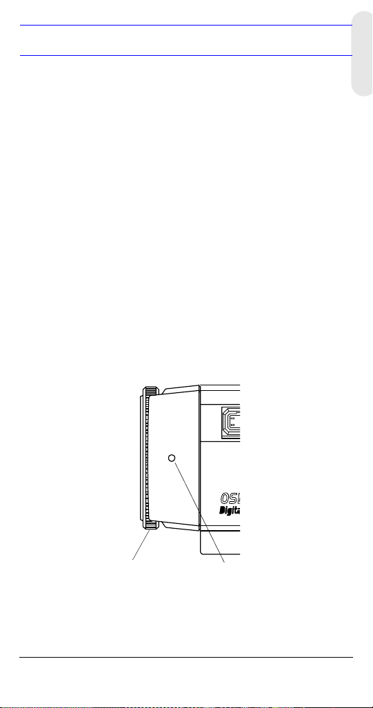
Figure 1 Camera Overview
C/CS mount adapter:
C mount: turn
counterclockwise
CS mount: turn clockwise
Lens connector for
Auto Iris lens plug
Setscrew: loosen locking ring
with “L” type wrench to adjust
mounting ring.
Features
• 1/3” IT Super HAD CCD
• Outstanding BLC implementation with Honeywell’s BMB
(Black Mask BLC) function
• C/CS adjustable lens mount adapter
• Excellent signal-to-noise ratio of more than 50 dB
• High sensitivity: minimum illumination of 0.001 lux (F1.2, 30
IRE, DSS x 128)
• 2-way Auto Iris: Video Iris or Direct Drive (DC) Iris lens
•OSD control
• External synchronization with line lock and auto detection
• RS485 remote control
English
Rev 1.01 1 900.0512
07/06
Page 10

Before You Begin
Please read this guide carefully before
you install the HCC484TP camera.
Keep this guide for future reference.
Unpack Everything
Check that the items received match those listed on the order form
and packing slip. The HCC484TP packing box should include, in
addition to this User Guide:
• One HCC484TP camera • One 4-pin connection cable
• One L-type wrench • One Auto Iris lens plug
If any parts are missing or damaged, contact the dealer you
purchased the camera from or call Honeywell Customer Service
(see Contact Information on the back of this manual).
Rev 1.01 2 900.0512
07/06
Page 11

Lens Installation
Installing a C/CS Mount Lens
1. Remove the protective cap from the front of the camera.
2. Adjust the C/CS mount ring for either C or CS mount.
a. Loosen the setscrews using the L-type wrench supplied.
b. Turn the mount ring counterclockwise for a C-mount lens
or clockwise for a CS-mount lens.
c. Tighten the setscrews.
3. Press the threaded portion of the lens mount against the
threaded portion of the camera mount and slowly screw the
lens clockwise until secure.
Figure 2 C/CS Mount
English
C
CS
Setscrews (x2)
Installing an Auto Iris Lens
1. Remove the cover of the auto iris lens plug and connect with
the lens cable.
2. Connect the auto iris lens plug to the 4-pin lens terminal on the
side of the camera.
Rev 1.01 3 900.0512
07/06
Page 12
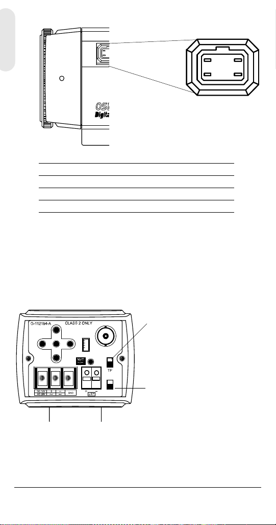
Figure 3 Auto Iris Lens Pin Definition
4-pin lens terminal
21
43
Pin DC (Direct Drive) lens Video (VSD) lens
1CTRL - Power (+12V)
2CTRL + NC
3DRV + Video Signal
4DRV - GND
3. Set the EE MODE to ALC MODE on the OSD menu (see ELC /
ALC Mode on page 13).
Auto iris lens with amplifier: Set the VSD LENS on the OSD
menu.
Auto iris lens with no amplifier: Set the DC LENS on the OSD
menu. Adjust to the LEVEL carefully to avoid hunting.
4. Set the switch on the rear of the camera to DC or VSD.
Video Output Selection Switch:
UP
MENU
-
DOWN
VIDEO
CONT
+
CV
VSD
DC
Set to CV for Composite Video.
Set to TP for UTP Video.
Set to VSD for an auto iris lens with a builtin amplifier (video-type lens).
Set to DC for an auto iris lens without an
amplifier (DC-type lens).
Auto iris lens: Use the connection recommended by the
manufacturer. For best practices, read the lens manual
carefully. You may need to set the flange back focus.
Rev 1.01 4 900.0512
07/06
Page 13
Adjusting the Flange Back Focus
Fixed Lens
1. Loosen the setscrew and set the lens focus ring to infinity (∞).
2. Turn the back focus adjustment ring until you see a clear
image (the distance from the camera to the object is more than
23 m).
3. Tighten the setscrew.
Zoom Lens
1. Loosen the setscrew and set the lens to the maximum
telephoto position.
2. Turn the back focus adjustment ring to adjust the focus.
3. Auto iris lens: Aim the camera at a comparatively dark object or
reduce the ambient light so that the iris is fully open.
4. Set the lens to its maximum wide angle position, then set the
focus.
5. Repeat steps 2, 3 and 4 until the difference between the
focusing positions is as small as possible.
6. Tighten the setscrew when the best focusing point is found.
Figure 4 Flange Back Focus
English
Back focus adjustment
ring
Rev 1.01 5 900.0512
Setscrew
07/06
Page 14
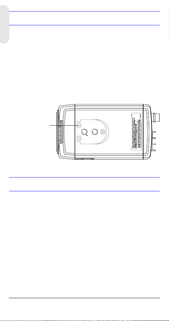
Mounting the Camera
Mounting points are provided on the top of the camera for mounting
the camera on a bracket or tripod. They are designed to accept
standard sized mounting bolts. This bracket can be unscrewed and
mounted onto the opposite side of the camera, depending on your
application. The mounting bracket must be capable of supporting
the weight of the camera and its lens.
Note Some installation codes dictate that the mounting
bracket must be capable of supporting up to four
times the combined weight of the camera and lens.
Figure 5 Camera Mount
Unscrew 3 bracket
securing screws and
then resecure the
bracket on the other
side of the camera.
Connecting the Camera
Note Check the power source from the external power
supply before applying power to the camera.
1. Connect the VIDEO connector on the rear of the camera to the
video-in connector on your monitor.
2. Connect the camera to a 12 VDC or 24 VAC power supply
(appropriate for your installation).
3. Plug in the power supply. The power LED illuminates to show
that the camera is receiving power. If it does not illuminate,
check the connections and the power source.
WARNING! The use of a CSA Certified/UL Listed
Class 2 power supply is required to
ensure compliance with electrical
safety standards.
Rev 1.01 6 900.0512
07/06
Page 15

Figure 6 Camera Connections
Power LED
Monitor
UP
MENU
-
DOWN
VIDEO
CONT
+
CV
VSD
DC
Remote Control Connections
The HCC484TP can be controlled remotely using an RS485
connection.
Figure 7 Camera Connection via RS485
Serial Port
(COM1 or
COM2)
Serial
cable
4-Pin Cable Legend
1. Red Not used
2. Blue TRx-
3. Yellow TRx+
4. Black Not used
RS485
converter
4P CableConnect to
UP
MENU
-
DOWN
VIDEO
CONT
+
English
CV
VSD
DC
RS485 Converter
TRx+
TRx-
4P Cable
3 TRx+
2 TRx-
Remote Access Software Program On your PC (optional).
Connect with cable through the serial port on your PC to
simulate task buttons for configuration.
Rev 1.01 7 900.0512
07/06
Page 16

Programming
Understanding the On-Screen Display
Press MENU briefly to confirm the current operation setup. The
information (see Figure 8) will disappear after a few seconds if there
is no button action.
Even though the OSD message disappears the Camera ID or Title
will continue to display. If you do not wish to display the ID, you can:
• With external communication, change the display position.
Options are: Bottom right, Bottom left, Top left, Top right, Non
display.
Figure 8 OSD Information Display
CAM ID/TITLE
Back
Light
CAM ID/TITLE CAM ID/TITLE
Shutter
Speed
CAM ID/TITLE
WB
Mode
Note If you do not need to display the Operating OSD (for
example, for an external text overlay board), it can
be set to OFF at all times through a remote control
using RS485 connection.
On-Screen Display
Use the OSD (On-Screen Display) to program the camera.
1. Press and hold the MENU (center) button for 2 seconds to
display the Setup menu.
2. Press the UP or DOWN buttons to select a menu item.
3. Press the MENU button to enter the selected submenu.
Rev 1.01 8 900.0512
07/06
Page 17

4. Press the + or – buttons to increase/decrease the value of the
+
selected item.
Figure 9 OSD Menu Controls
UP
MENU
DOWN
Saving your Settings
First Method: When you are satisfied with your settings:
1. Press MENU for two seconds. The SETUP Menu is replaced
by one of two messages:
SAVE? displays when values have been changed. Selecting
SAVE exits Setup mode and saves your changes.
QUIT? displays when you have not changed any settings.
Selecting QUIT exits Setup mode without saving any changed
values.
2. Press + or – to select SAVE or QUIT and press MENU to exit
the Setup mode. Press the UP or DOWN buttons to cancel the
SAVE/QUIT and return to the SETUP MENU.
Second Method: Select EXIT MENU on the SETUP MENU, press
MENU, and select SAVE AND EXIT to save the changed settings
and exit the menu. Select EXIT to exit without saving the settings.
English
Rev 1.01 9 900.0512
07/06
Page 18

OSD Menu Structure
The HCC484TP menu system consists of one main SETUP MENU
(see Figure 10) for easy camera programming.
Figure 10 Menu Structure
<<SETUP MENU>>
CAMERA ID 002 …
1
ELC / ALC ALC …
2
SHUTTER 1/50
3
WB CONTROL ATW …
4
AGC CONTROL 34dB
5
DSS CONTROL AUTO
6
MAX FIELD x128
7
SYNC. CONT. AUTO …
8
RESTORE DEFAULT …
9
EXIT MENU …
… indicates submenus
SETUP
MENU
Camera ID, Title and Display Position
ELC Mode: AUTO, MANUAL
ALC Mode: VSD LENS
ATW, Outdoor, Indoor, User, Fluorescent
AWC (Auto, Manual; Push and Lock)
MWB (RED, BLUE)
AUTO, INTERNAL, Line Lock (V.PH)
DC LENS (Level)
SETUP
MENU
CAMERA ID
ELC/ALC MODE
SHUTTER SPEED
WHITE BALANCE
AGC CONTROL
DSS CONTROL
MAX FIELD
SYNC CONTROL
RESTORE DEFAULT
EXIT MENU
SETUP MENU Functions
Menu Item Option Description
CAMERA ID000 (off), 001 … 255 ID set to 0 will turn ID display
1
ELC / ALC
2
Mode
Rev 1.01 10 900.0512
ELC …
ALC …
off.
See ELC / ALC Mode for
more information.
07/06
Page 19

Menu Item Option Description
SHUTTER
3
SPEED
WB
4
CONTROL
(White
Balance)
AGC
5
CONTROL
DSS
6
CONTROL
MAX FIELD
7
CONTROL
1/60 NTSC (1/50
PAL)
FL
1/250, 1/500, 1/1000,
1/2000, 1/4000,
1/10000, 1/30000,
1/50000
ATW
AWC
MWB
OFF
10 dB
12 dB … 38 dB
OFF
AUTO
FIX
OFF
x2, x4, x6, x8, x10,
x16, x32, x64, x128
Adjust brightness with high
shutter speed.
Flicker
This field is not adjustable
when the camera is set to
ELC MODE. Auto is
selected by default.
White balance mode, auto
and manual.
Preset white balance modes
include INDOOR,
FLUORESCENT, USER and
OUTDOOR.
Adjust maximum value of
AGC gain.
If the DSS CONTROL
(Sensitivity UP) Mode is set
to AUTO or FIX, you can
adjust the AGC from 18 dB
to 38 dB.
Compensate for low
illumination. Adjust the
maximum integration fields
to get a brighter dynamic
image. The scene will be
slower than when set to
OFF.
The larger this field, the
greater the noise of the
image. For more dynamic
range, adjust the MAX FIELD
and increase the AGC
CONTROL setting.
English
Rev 1.01 11 900.0512
07/06
Page 20

Menu Item Option Description
SYNC
8
CONTROL
AUTO
INT
See Sync Control Setup for
more information.
L/L
RESTORE
9
DEFAULT
RESTORE DEFAULT
SETTINGS
Restore the factory default
settings. If you have not
made any changes, you will
not be able to select this
setting.
Adding a Camera Title Display
To add a camera title:
1. Enter the SETUP MENU, select CAMERA ID and press MENU.
2. Use the UP, DOWN, +, – buttons to select a character in the
TITLE to start editing with.
3. When the position is set, use the UP, DOWN, +, – buttons to
move between the alphanumeric characters. When the desired
character is blinking, press MENU to accept it. The character
appears in the title at the bottom of the screen. The cursor will
automatically highlight the next position in the TITLE.
4. Repeat step 2 until your camera title is complete.
5. Use the + and – buttons to change the DISPLAY field to
TITLE.
6. Select RETURN and press MENU to accept your changes and
return to the main SETUP MENU.
Note For remote control using RS485 connection, you can
select either Camera ID or Title to display.
Figure 11 Adding Camera Title
CAM ID: 002
DISPLAY: TITLE
POSITION: T.R.
1 2 3 4 5 6 7 8 9 A B C D E F
G H I J K L M N P Q R S T U V W
X Y Z a b c d e f g h i j k l m
n o p q r s t u v w x y z , . :
; ~ ! ? $ % * & / < > + - = ■
TITLE: HCC484TP■■
RETURN
Rev 1.01 12 900.0512
07/06
Page 21

CAMERA ID Menu Functions
Menu Item Option Description
CAM ID OFF, 001
… 255
The number assigned each camera in
your network, from 000 to 255. When set
to 000 the ID is not displayed on the
screen.
DISPLAY TITLE, ID,
OFF
POSITION T.R., B.R.,
B.L., T.L.,
NO DISP
Select what is displayed on the screen
(Camera TITLE, ID or nothing).
Select where you want the Camera ID or
Title to appear on the display (Top Right,
Bottom Right, Top Left, Bottom Left and
No Display).
TITLE Enter a name for the camera, maximum
10 characters, including spaces.
RETURN Press MENU to return to the main
SETUP MENU.
Setting the Camera Lighting Optimization
ELC / ALC Mode
Figure 12 Setting Camera Lighting
<ELC / ALC MODE>
EE MODE: ALC MODE
BLC MODE: OFF
BMB MODE: OFF
RETURN
DC LENS
LEVEL 06
English
Rev 1.01 13 900.0512
07/06
Page 22

To set the lens mode, back light compensation and black mask:
Menu Item Option Description
EE MODE:
ELC MODE
AUTO
MANUAL
For a manual (fixed) lens:
AUTO: Iris operates electronic
exposure automatically.
MANUAL: Adjust the iris by changing
the high shutter speed manually.
EE MODE:
ALC MODE
VSD
LENS
DC LENS
For an automatic iris lens:
VSD: Select for video-type lens.
DC LENS: Select for direct drive-type
lens. Adjust the LEVEL until the
image is neither too bright nor too
dark.
Backlight
Compensation
BLC MODE
OFF
LOW BL
MID. BL
Prevents the object in the center of
the image from darkening when
there is excessive light from behind.
HIGH BL
Note When BLC MODE is set,
BMB MODE is disabled.
Black Mask
BMB MODE
OFF
L. GRAY
D. GRAY
BLACK
Another function of BLC that masks
excessive light to a dark level and
makes the image brighter so the
object is clear.
Note When BMB Mode is set, BLC
MODE is disabled.
RETURN Press MENU to return to the SETUP
MENU.
Rev 1.01 14 900.0512
07/06
Page 23

White Balance Control Setup
To set how the camera tracks to accept different lighting conditions
within the color range of 2800°K to 8000°K:
Figure 13 White Balance Control
<WHITE BALANCE>
WB MODE: MWB
WB CONT: R=00
RETURN
Menu Item Description
ATW (Auto Trace
White Balance
Feedback system that automatically aligns the
white balance (2800°K to 8000°K).
Mode)
AWC (Auto White
Balance Control
Mode)
Performs faster action than ATW mode without
an operating range. Options are:
AUTO: AWC operates all the time
MANUAL: PUSH = Press to start the AWC
operation
MANUAL: LOCK = Release key to fit the
present shooting scene’s white balance
INDOOR General indoor scenes preset (3200°K).
FLUORESCENT Office environments with fluorescent or
tungsten lighting. Provides lowest dynamic
range of all presets (4200°K).
USER FIXED Preset (4700°K)
OUTDOOR Preset for outside environments and high-
contrast scenes where the camera is focused
on the darker (6300°K).
MWB
(Manual Mode)
RED: 0 – 20
BLUE: 0 – 20
RETURN Press MENU to return to the SETUP MENU.
B=00
English
Rev 1.01 15 900.0512
07/06
Page 24

Sync Control Setup
To synchronize the vertical interval sync pulse of your camera with
other equipment to reduce the effect of picture roll on the monitor.
Figure 14 Sync Control Setup
<SYNC. CONTROL>
SYNC MODE: AUTO
RETURN
INTERNAL
Menu Item Description
INTERNAL When line lock is not required.
LINELOCK Adjust the proper phase:
V.PH: 000 – 300 (factory default is 0)
RETURN Press MENU to return to the SETUP MENU.
Restore Factory Default Settings
To reload the factory default settings on the camera.
Figure 15 Restoring Default Settings
<RESTORE DEFAULT>
RESTORE FACTORY SETTING
RETURN
Menu Item Description
RESTORE Press MENU to Reload the factory default camera
settings.
This action replaces all user-defined settings.
RETURN Press MENU to return to the SETUP MENU.
Rev 1.01 16 900.0512
07/06
Page 25

Exit Setup Menu
To exit the SETUP menu.
Figure 16 Exit Menu
<EXIT MENU>
SAVE AND EXIT
EXIT
RETURN
Menu Item Description
SAVE AND EXIT Press MENU to save your changes and exit.
EXIT Press MENU to quit without saving your
changes.
RETURN Press MENU to return to the SETUP MENU.
English
Rev 1.01 17 900.0512
07/06
Page 26

Specifications
Camera HCC484TP (NTSC) HCC484TPX (PAL)
Imaging device: 1/3” CCD (total
Effective pixel: 768 (H) x 494 (V)
Scanning system: 525 lines, 2:1
Sync system: Internal, Line lock,
Scanning
frequency:
Horizontal
Resolution:
Video out: VBS 1.0 Vp-p / BNC
S/N ratio: more than 50 dB
Minimum
illumination:
BLC: OFF, Low, Middle, High
BMB: OFF, Light Gray, Dark Gray, Black
Auto Electronic
Shutter:
AGC: OFF ~ 38 dB
ALC: Auto Iris: Video drive/DC drive
White Balance: ATW/AWC/Indoor/Outdoor/Fluorescent/
Lens mount: C/CS mount
Power source: 24 VAC ± 20%, 12 VDC ± 2V, Max 3W
Temperature: Operating: 14°F ~ 122°F (-10°C ~ +50°C)
Enclosure
Dimension:
(W x H x D)
Weight: 0.84 lb. (380 kg)
410,000 pixels)
(380,000 pixels)
interlace
Auto
15.734 KHz (H)
59.94 Hz (V)
less than 0.1 lux (F1.2, 30 IRE, AGC ON)
DSS ON 0.001 lux (x128 fields)
1/60s ~ 1/15,000 sec
(10 steps)
Manual/One Push WB
Storage: -4°F ~ 158°F (-20°C ~ +70°C)
2.68 in. x 2.2 in. x 4.72 in.
(68 mm x 56 mm x 120 mm)
1/3” CCD (total
470,000 pixels)
752 (H) x 582 (V)
(440,000 pixels)
625 lines, 2:1
interlace
Internal, Line lock,
Auto
15.625 KHz (H)
50.0 Hz (V)
480 TVL
1/50s ~ 1/15,000 sec
(10 steps)
Rev 1.01 18 900.0512
07/06
Page 27

Page 28

Honeywell Video Systems (Head office)
2700 Blankenbaker Pkwy, Suite 150
Louisville, KY 40299, USA
www.honeywellvideo.com
℡
+1.800.796.2288
Honeywell Security Australia Pty Ltd.
Unit 5, Riverside Centre
24-28 River Road West
Parramatta, NSW 2150, Australia
www.ademco.com.au
℡
+61.2.8837.9300
Honeywell Security Asia Pacific
33/F Tower A, City Center, 100 Zun Yi
Road
Shanghai 200051, China
www.security.honeywell.com/cn
℡
+86 21.2527.4568
Honeywell Security Asia
Flat A, 16/F, CDW Building
388 Castle Peak Road
Tsuen Wan, N.T., Hong Kong
www.security.honeywell.com/hk
℡
+852.2405.2323
Honeywell Security France
Parc Gutenberg, 8, Voie La Cardon
91120, Palaiseau, France
www.honeywell.com/security/fr
℡
+33.01.64.53.80.40
Honeywell Security Italia SpA
Via Treviso 2 / 4
31020 San Vendemiano
Treviso, Italy
www.honeywell.com/security/it
℡
+39.04.38.36.51
Honeywell Security España
Mijancas 1. 3
P.Ind. Las Mercedes
28022 Madrid, Spain
www.security.honeywell.com/es
℡
+34.902.667.800
a
Planta
Honeywell Video Systems
Northern Europe
Netwerk 121
1446 WV Purmerend, The Netherlands
www.SecurityHouse.nl
℡
+31.299.410.200
Honeywell Video Systems UK Ltd.
Aston Fields Road, Whitehouse Ind Est
Runcorn, Cheshire, WA7 3DL, UK
www.honeywellvideo.com
℡
+0844 8000 235
Honeywell Security South Africa
Unit 6 Galaxy Park, 17 Galaxy Avenue
Linbro Park, P.O. Box 59904
2100 Kengray, Johannesburg
South Africa
www.honeywell.co.za
℡
+27.11.574.2500
Honeywell Security Germany
Johannes-Mauthe-Straße 14
D-72458 Albstadt, Germany
www.honeywell.com/security/de
℡
+49.74 31.8 01.0
Honeywell Security Poland
Chmielewskiego 22a, 70-028
Szczecin, Polska
www.ultrak.pl
℡
+48.91.485.40.60
Honeywell Security Czech Republic
Havránkova 33, Brno
Dolní Heršpice, 619 00
Czech Republic
www.olympo.cz
℡
+420.543.558.111
Honeywell Security Slovakia Republic
Vajnorská 142, 83104 Bratislava
Slovakia
www.olympo.sk
℡
+421.2.444.54.660
Honeywell Video Systems
www.honeywellvideo.com
+1.800.796.CCTV (North America only)
HVSsupport@honeywell.com
Document 900.0512 07/06 Rev. 1.01
© 2006 Honeywell International Inc. All rights reserved. No part of this publication may be
reproduced by any means without written permission from Honeywell Video Systems. The
information in this publication is believed to be accurate in all respects. However, Honeywell
Video Systems cannot assume responsibility for any consequences resulting from the use
thereof. The information contained herein is subject to change without notice. Revisions or
new editions to this publication may be issued to incorporate such changes.
P/N: G-112656-002
Page 29

Caméra CCD couleur
NTSC
HCC484TP HCC484TPX
PAL
Guide d’utilisation
Français
Document 900.0512 – 07/06 – Rév. 1.01
Page 30

Révisions
Version Date Révisions
1.00 07/06 Nouveau document
1.01 07/06 Numéro de document corrigé à G-
112656-002.
Rév. 1.01 ii 900.0512
07/06
Page 31

Explication des symboles
graphiques
Ce symbole indique la présence d’une
« tension dangereuse » non isolée dans
le boîtier du produit qui peut être
suffisamment importante pour constituer
un risque de choc électrique.
Ce symbole indique la présence
d’instructions importantes sur le
fonctionnement et la maintenance
(entretien) dans la documentation
fournie avec le produit.
ATTENTION
RISQUE DE CHOC
ÉLETRIQUE.
NE PAS OUVRIR
Français
ATTENTION: POUR RÉDUIRE LE RISQUE DE CHOC
ÉLECTRIQUE, NE RETIREZ PAS LE COUVERCLE.
AUCUNE PIÈCE DONT L'ENTRETIEN PEUT ÊTRE
ASSURÉ PAR L'UTI L I SATEUR NE SE TROUVE À
L'INTÉRIEUR. CONFIEZ LA MAINTENANCEÀ
DES TECHNICIENS QUALIFIÉS SPÉCIALISÉS
Rév. 1.01 iii 900.0512
DANS L'ENTRETIEN
07/06
Page 32

Avertissements
Les opérations d’installation et d’entretien ne doivent être effectuées
que par du personnel qualifié et expérimenté.
Pour des applications à l’extérieur, utilisez un Coffret de protection
approprié, conformément à la norme IP65.
Pour éviter tout risque de feu ou de choc
électrique, ne pas exposer cette caméra
à la pluie ou à l’humidité.
Précautions
Cette caméra est conçue pour être utilisée dans des applications de
surveillance courantes à l’intérieur à l’exception de toute autre fin.
N’utilisez votre caméra qu’à des températures comprises entre
-10°C et +50°C (14°F et 122°F).
Ne pas utiliser la caméra en dehors de la plage de puissance
recommandée.
La caméra ne doit être utilisée que dans des environnements
propres, secs et exempts de poussière à moins d’être protégée
dans un coffret de protection adapté respectant au minimum les
exigences de la norme IP65.
Rév. 1.01 iv 900.0512
07/06
Page 33

Déclaration de conformité FCC
Informations aux utilisateurs : Ce matériel a été testé et déclaré
conforme aux limites d’un appareil numérique de classe A.
Conformément à la partie 15 du règlement FCC, ces limites sont
destinées à apporter une protection raisonnable contre les
interférences nuisibles lorsque cet équipement est utilisé dans un
environnement industriel. Ce matériel produit, utilise et peut
rayonner des radiofréquences et, s’il n’est pas installé et utilisé
conformément au manuel d’installation, peut perturber les
communications radio. L’utilisation de ce matériel dans une zone
résidentielle peut occasionner des perturbations, auquel cas il
incombe aux utilisateurs de prendre les mesures nécessaires pour
y remédier et ce, à leurs frais.
Caution Toute modification de ce matériel, non
expressément autorisée par la partie responsable de
la conformité, peut entraîner l’interdiction de
l’utiliser.
Déclaration de conformité du fabricant
Le fabricant déclare que le matériel fourni avec ce guide est
conforme aux exigences essentielles de protection de la directive
EMC 89/336/EEC et de la directive Basse tension 73/23/CEE,
conformément aux exigences des normes EN 55013 sur les
émissions.
Français
Rév. 1.01 v 900.0512
07/06
Page 34

Page 35

Sommaire
Introduction . . . . . . . . . . . . . . . . . . . . . . . . . . . . . . . . . . . . 1
Caractéristiques . . . . . . . . . . . . . . . . . . . . . . . . . . . . . . . 1
Avant de commence. . . . . . . . . . . . . . . . . . . . . . . . . . . . .2
Déballage . . . . . . . . . . . . . . . . . . . . . . . . . . . . . . . . . . . . 2
Installation de l’objectif . . . . . . . . . . . . . . . . . . . . . . . . . . . 3
Installation d’un objectif à monture C/CS . . . . . . . . . . . .3
Installation d’un objectif à diaphragme automatique. . . 3
Réglage du tirage optique . . . . . . . . . . . . . . . . . . . . . . . 5
Objectif fixe . . . . . . . . . . . . . . . . . . . . . . . . . . . . . . . . .5
Zoom . . . . . . . . . . . . . . . . . . . . . . . . . . . . . . . . . . . . . 5
Montage de la caméra . . . . . . . . . . . . . . . . . . . . . . . . . . .6
Branchement de la caméra . . . . . . . . . . . . . . . . . . . . . . 6
Programmation . . . . . . . . . . . . . . . . . . . . . . . . . . . . . . . . . . 8
Comprendre l’affichage à l’écran . . . . . . . . . . . . . . . . . . 8
Affichage à l’écran . . . . . . . . . . . . . . . . . . . . . . . . . . . . . .8
Enregistrement de vos paramètres . . . . . . . . . . . . . . . . .9
Structure du menu d’affichage à l’écran. . . . . . . . . .10
Fonctions du menu SETUP MENU
(MENU CONFIGURATION) . . . . . . . . . . . . . . . . . . .10
Ajout d’un affichage de titre de caméra . . . . . . . . . .12
Réglage de l’optimisation de l’éclairage de la caméra . 13
Mode de contrôle de lumière (ELC / ALC) . . . . . . .13
Configuration du contrôle de la balance des blancs 15
Configuration du contrôle de la synchronisation . . 16
Rétablir les paramètres d’usine par défaut . . . . . . . 16
Quitter le Menu Setup (Configuration) . . . . . . . . . . 17
Caractéristiques . . . . . . . . . . . . . . . . . . . . . . . . . . . . . . . . 18
Français
Rév. 1.01 vii 900.0512
07/06
Page 36

Page 37

Introduction
p
La caméra HCC484TP d’Honeywell est une caméra couleur CCD
avec sensibilité faible lumière dotée d’un obturateur numérique lent,
d’un câble UTP et d’un contrôle à distance via une liaison RS485.
Figure 1 Vue d’ensemble de la caméra
Adaptateur de monture C/CS :
Monture C : tournez vers la
gauche
Monture CS : tournez vers la
droite
Connecteur d’objectif
pour fiche d’objectif à
diaphragme automatique
Vis sans tête : desserrez la bague de
verrouillage à l’aide de la clé coudée pour
ouvoir régler la bague de montage.
Caractéristiques
• Capteur 1/3 pouces IT-CCD Super HAD
• Extraordinaire application de la compensation contre-jour
grâce à la fonction BMB (Black Mask BLC) d’Honeywell
(technologie permettant une compensation renforcée)
• Adaptateur de monture de l’objectif réglable C/CS :
• Excellent rapport signal/bruit supérieur à 50 dB
• Haute sensibilité : luminosité minimale de 0,001 lux
(F1.2 ; 30 IRE, obturateur numérique lent x 128)
• Ouverture et fermeture automatiques du diaphragme : objectif
à iris vidéo ou à iris DC
• Contrôle par affichage à l’écran
• Synchronisation externe avec verrouillage de ligne et détection
automatique
• Contrôle à distance via RS485
Français
Rév. 1.01 1 900.0512
07/06
Page 38

Avant de commencer
Veuillez lire attentivement le présent guide
avant d’installer la caméra HCC484TP.
Gardez ce guide pour un usage ultérieur.
Déballage
Contrôlez que les éléments reçus correspondent à ceux répertoriés
sur le formulaire de commande et le bordereau de livraison.
L’emballage de la caméra HCC484TP devrait contenir, outre le
présent Guide d’utilisation :
• Une caméra HCC484TP • Un câble de branchement à
• Une clé coudée • Une fiche d’objectif à
Si certaines pièces sont manquantes ou endommagées, contactez
le vendeur auprès duquel vous avez acheté la caméra ou appelez le
service clientèle d’Honeywell (voir Informations de contact au dos
de ce manuel).
4 broches
diaphragme automatique
Rév. 1.01 2 900.0512
07/06
Page 39

Installation de l’objectif
Installation d’un objectif à monture C/CS
1. Déposez le cache protecteur de la partie frontale de la caméra.
2. Réglez la bague de monture C/CS pour une monture C ou CS.
a. Desserrez les vis sans tête à l’aide de la clé coudée
fournie.
b. Tournez la bague de montage dans le sens inverse des
aiguilles d’une montre pour un objectif à monture C ou dans
le sens des aiguilles d’une montre pour un montage CS.
c. Serrez les vis sans tête.
3. Appuyez la partie filetée de la monture de l’objectif contre la
partie filetée de la monture de la caméra et vissez lentement
l’objectif vers la droite jusqu’à ce qu’il soit fixé.
Figure 2 Monture C/CS
Français
C
CS
Vis sans tête (x2)
Installation d’un objectif à diaphragme automatique
1. Déposez le cache de la fiche d’objectif à diaphragme
automatique et effectuez la connexion à l’aide du câble de
l’objectif.
2. Branchez la fiche d’objectif à diaphragme automatique dans la
prise de l’objectif à quatre broches situées sur le côté de la
caméra.
Rév. 1.01 3 900.0512
07/06
Page 40

Figure 3 Définition des broches de l’objectif
àdiaphragme automatique
Prise d’objectif à quatre broches
21
43
Broche Objectif DC (Direct Drive) Objectif vidéo (VSD)
1 CTRL - Alimentation (+12 V)
2 CTRL + NC (non connectée)
3 DRV + Signal vidéo
4DRV - Masse
2. Réglez le MODE EE (exposition automatique) sur le MODE ALC
(contrôle de lumière automatique) sur le menu d’affichage à
l’écran (
voir Mode de contrôle de lumière (ELC / ALC) à la
page 13
).
Objectif à diaphragme automatique avec amplificateur : réglez
l’OBJECTIF VSD sur le menu d’affichage à l’écran.
Objectif à diaphragme automatique sans amplificateur : réglez
l’OBJECTIF DC sur le menu d’affichage à l’écran. Ajustez au
NIVEAU minutieusement afin d’éviter tout balayage
intempestif.
3. Placez l’interrupteur situé à l’arrière de la caméra sur DC ou VSD.
Commutateur de sélection de la sortie
VIDEO
UP
CONT
MENU
-
DOWN
+
CV
VSD
DC
vidéo :
À placer sur CV pour vidéo composite
(Composite Video).
À placer sur TP pour vidéo UTP.
Réglez sur VSD pour un objectif à
diaphragme automatique avec
amplificateur intégré (objectif vidéo).
Réglez sur DC pour un objectif à
diaphragme automatique sans
amplificateur (objectif DC).
Objectif à diaphragme automatique : utilisez le branchement
recommandé par le fabricant. Pour connaître les meilleures
méthodes, lisez attentivement le manuel de l’objectif. Il se peut
que vous deviez régler le tirage optique.
Rév. 1.01 4 900.0512
07/06
Page 41

Réglage du tirage optique
Objectif fixe
1. Desserrez la vis sans tête et réglez la bague de focale de
l’objectif sur l’infini (∞).
2. Faites tourner la bague de réglage du tirage optique jusqu’à
obtenir une image claire (la distance entre la caméra et l’objet
est supérieure à 23 m).
3. Resserrez la vis sans tête.
Zoom
1. Desserrez la vis sans tête et réglez l’objectif sur la position de
téléobjectif maximale.
2. Faites tourner la bague de réglage du tirage optique pour
ajuster la focale.
3. Objectif à diaphragme automatique : visez un objet
relativement sombre ou réduisez la lumière ambiante de sorte
que le diaphragme soit complètement ouvert.
4. Placez l’objectif dans sa position de grand angle maximale,
puis réglez la focale.
5. Répétez les étapes 2, 3 et 4 jusqu’à ce que la différence entre
les positions de mise au point soit la plus réduite possible.
6. Lorsque vous avez trouvé la meilleure mise au point, serrez la
vis sans tête.
Figure 4 Tirage optique
Français
Bague de réglage du
tirage optique
Rév. 1.01 5 900.0512
Vis sans tête
07/06
Page 42

Montage de la caméra
Des points de montage ont été placés au sommet de la caméra
dans le but de monter celle-ci sur un support ou un trépied. Ces
points sont conçus pour des boulons de taille standard. Ce support
peut-être dévissé et monté de l’autre côté de la caméra selon les
besoins de votre application. Le support de montage doit être à
même de supporter le poids de la caméra et de son objectif.
RemarqueCertains codes d’installation imposent que le support de
montage soit en mesure de supporter jusqu’à quatre fois
le poids combiné de la caméra et de l’objectif.
Figure 5 Montage de la caméra
Dévissez les 3 vis de
fixation du support
puis refixez ce dernier
de l’autre côté de la
caméra.
Branchement de la caméra
RemarqueVérifiez l’alimentation de la source externe avant de
mettre la caméra sous tension.
1. Branchez le connecteur VIDEO à l’arrière de la caméra dans le
connecteur video-in de votre moniteur.
2. Branchez la caméra à une alimentation 12 V CC ou 24 V CA
(selon votre installation).
3. Mettez sous tension. Le témoin d’alimentation s’allume pour
indiquer que la caméra est alimentée. Si ce n’est pas le cas,
vérifiez les branchements et la source d’alimentation.
WARNING! L’utilisation d’une alimentation de
classe 2 certifiée CSA/homologuée
UL s’impose pour garantir la
conformité aux normes de sécurité
électrique.
Rév. 1.01 6 900.0512
07/06
Page 43

Figure 6 Branchements de la caméra
Témoin d’alimentation
Moniteur
UP
MENU
-
DOWN
VIDEO
CONT
+
CV
VSD
DC
Connexions pour le contrôle à
distance
La caméra HCC484TP peut être contrôlée à distance via une
connexion RS485.
Figure 7 Connexion caméra via RS485
Convertisseur
au port série
(COM1 ou
COM2)
Légende du câble à quatre
broches
1. Rouge Non utilisé
2. Bleu TRx-
3. Jaune TRx+
4. Noir Non utilisé
Câble
série
RS485
Câble 4PConnectez
UP
MENU
-
DOWN
VIDEO
CONT
+
CV
VSD
DC
Français
Convertisseur RS485
TRx+
TRx-
Câble 4P
3 TRx+
2 TRx-
Programme logiciel d’accès à distance Sur votre PC (en
option). Branchez le câble au port série de votre PC afin de
simuler les boutons de tâches pour la configuration.
Rév. 1.01 7 900.0512
07/06
Page 44

Programmation
Comprendre l’affichage à l’écran
Appuyez brièvement sur MENU pour confirmer la configuration
actuelle. Les informations (voir Figure 8) s’afficheront au bout de
quelques secondes si aucun bouton n’a été actionné.
Même après disparition du message d’affichage à l’écran, le
numéro d’identification de la caméra ou le titre continueront de
s’afficher. Si vous ne souhaitez pas afficher le numéro
d’identification, vous pouvez :
• par le biais de la communication externe, modifier la position
d’affichage. Vous avez le choix entre les options suivantes : en
bas à droite, en bas à gauche, en haut à gauche, en haut à
droite, aucun affichage.
Figure 8 Affichage des informations de l’affichage
àl’écran
CAM ID/TITLE
Back
Light
CAM ID/TITLE CAM ID/TITLE
Shutter
speed
CAM ID/TITLE
WB
Mode
RemarqueSi vous n’avez pas besoin d’afficher l’écran d’affichage
d’exploitation (par exemple, pour carte de surimpression
textuelle), vous pouvez le configurer sur OFF
(DÉSACTIVÉ) à tout moment via un contrôle à distance
passant par la connexion RS485.
Affichage à l’écran
Utilisez l’affichage à l’écran pour programmer la caméra.
1. Appuyez sur le bouton MENU (centre) et maintenez-le enfoncé
pendant 2 secondes pour afficher le menu Setup
(Configuration).
Rév. 1.01 8 900.0512
07/06
Page 45

2. Appuyez sur les boutons UP (HAUT) ou DOWN (BAS) pour
+
sélectionner un élément du menu.
3. Appuyez sur MENU pour entrer dans le sous-menu
sélectionné.
4. Appuyez sur + ou – pour augmenter/diminuer la valeur de
l’élément sélectionné.
Figure 9 Contrôles du menu d’affichage à l’écran
UP
MENU
DOWN
Enregistrement de vos paramètres
Première méthode : Lorsque vos paramètres vous conviennent :
1. Appuyez sur MENU pendant deux secondes. Le menu SETUP
MENU (MENU CONFIGURATION) est remplacé par un ou
deux messages :
SAVE? (ENREGISTRER ?) s’affiche lorsque les valeurs ont été
modifiées. Si vous choisissez SAVE (ENREGISTRER), vous
quittez le mode de configuration après enregistrement de vos
modifications.
QUIT? (QUITTER ?) s’affiche lorsqu’aucun paramètre n’a été
modifié. Si vous choisissez QUIT (QUITTER), vous quittez le
mode de configuration sans enregistrer de modifications des
valeurs.
2. Appuyez sur + ou – pour sélectionner SAVE (ENREGISTRER)
ou QUIT (QUITTER) et appuyez sur MENU pour sortir du
mode de configuration. Appuyez sur les boutons UP (HAUT)
ou DOWN (BAS) pour annuler le choix SAVE/QUIT
(ENREGISTRER/QUITTER) et revenir au SETUP MENU (MENU
CONFIGURATION).
Français
Deuxième méthode : sélectionnez EXIT MENU (QUITTER LE
MENU) dans le SETUP MENU (MENU CONFIGURATION, appuyez
sur MENU, puis sélectionnez SAVE AND EXIT (ENREGISTRER ET
QUITTER) pour enregistrer les paramètres modifiés et quitter le
menu. Sélectionnez EXIT (QUITTER) pour quitter sans enregistrer
les paramètres.
Rév. 1.01 9 900.0512
07/06
Page 46

Structure du menu d’affichage à l’écran
Le système de menu de la caméra HCC484TP repose sur un menu
principal SETUP MENU (MENU CONFIGURATION) (voir Figure 10)
pour une question de facilité de programmation.
Figure 10 Structure du menu
<<SETUP MENU>>
CAMERA ID 002 …
1
ELC / ALC ALC …
2
SHUTTER 1/50
3
WB CONTROL ATW …
4
AGC CONTROL 34 dB
5
DSS CONTROL AUTO
6
MAX FIELD x128
7
SYNC. CONT. AUTO …
8
RESTORE DEFAULT …
9
EXIT MENU …
… indique la présence de sousmenus
CAMERA ID
ELC/ALC MODE
SHUTTER SPEED
WHITE BALANCE
SETUP
MENU
AGC CONTROL
DSS CONTROL
MAX FIELD
SYNC CONTROL
RESTORE DEFAULT
EXIT MENU
Numéro d’identification de la caméra, titre et
position de l’affichage
Mode de contrôle de lumière électronique :
AUTO (AUTOMATIQUE),
MANUAL (MANUEL)
Mode de contrôle de lumière automatique :
VSD LENS (OBJECTIF VSD)
DC LENS (OBJECTIF DC) (Level [Niveau])
Ajustement automatique de la balance des
blancs, extérieur, intérieur, utilisateur, fluorescent
AWC (Contrôle automatique de la balance des
blancs) (Auto, Manual; Push and Lock [Auto,
Manuel ; Pousser et verrouiller])
MWB (Balance des blancs manuelle) (RED
[ROUGE], BLUE [BLEU])
AUTO, INTERNE, Verrouillage de ligne [phase V]
SETUP
MENU
Fonctions du menu SETUP MENU (MENU CONFIGURATION)
Élément
de menu
CAMERA ID
1
(NUMÉRO
D’IDENTIFICA
TION DE LA
CAMÉRA)
Mode de
2
contrôle de
lumière (ELC /
ALC)
Rév. 1.01 10 900.0512
Option Description
000 (désactivé),
001 … 255
ELC …
ALC …
Si le numéro d’identification est
défini sur 0, il ne sera pas affiché.
Voir Mode de contrôle de lumière
(ELC / ALC) pour plus
d’informations.
07/06
Page 47

Élément
de menu
SHUTTER
3
SPEED
(VITESSE
D’OBTURATI
ON)
WB
4
CONTROL
(White
Balance)
(CONTROLE
DE LA
BALANCE
DES
BLANCS)
AGC
5
CONTROL
(CONTRÔLE
DE GAIN
AUTOMATIQ
UE)
DSS
6
CONTROL
(CONTRÔLE
DE
L’OBTURATE
UR
NUMÉRIQUE
LENT)
MAX FIELD
7
CONTROL
(CONTRÔLE
CHAMP
MAX.)
SYNC
8
CONTROL
(CONTRÔLE
DE LA
SYNCHRONI
SATION)
RESTORE
9
DEFAULT
(RÉTABLIR
PAR
DÉFAUT)
Option Description
1/60 NTSC (1/50 PAL)
FL
1/250, 1/500, 1/1000, 1/
2000, 1/4000,
1/10000, 1/30000,
1/50000
ATW (AJUSTEMENT
AUTOMATIQUE DE LA
BALANCE DES BLANCS)
AWC (CONTRÔLE
AUTOMATIQUE DE LA
BALANCE DES BLANCS)
MWB (BALANCE DES
BLANCS MANUELLE)
OFF (DÉSACTIVÉ)
10 dB
12 dB … 38 dB
OFF (DÉSACTIVÉ)
AUTO
FIX (FIXE)
OFF (DÉSACTIVÉ)
x2, x4, x6, x8, x10, x16,
x32, x64, x128
AUTO
INT (INTERNE)
L/L (VERROUILLAGE DE
LIGNE)
RESTORE DEFAULT
SETTINGS (RETABLIR
LES PARAMETRES PAR
DEFAUT)
Pour régler la luminance avec une
vitesse d’obturation élevée.
Clignotement
Il est impossible de régler ce
champ lorsque la caméra est
configurée sur ELC MODE (MODE
ELC). Auto est sélectionné par
défaut.
Mode de balance des blancs, auto
et manuel.
Les modes prédéfinis de balance
des blancs sont les suivants :
INDOOR (INTÉRIEUR),
FLUORESCENT, USER
(UTILISATEUR) et OUTDOOR
(EXTÉRIEUR).
Pour ajuster la valeur minimale du
gain AGC (contrôle de gain
automatique).
Si le mode DSS CONTROL
(Sensitivity UP) [CONTRÔLE DE
L’OBTURATEUR NUMÉRIQUE
LENT (Sensibilité HAUTE)] est
défini sur AUTO ou FIX (FIXE), vous
pouvez régler le contrôle de gain
automatique de 18 dB à 38 dB.
Pour compenser un éclairage
faible. Ajustez les champs
d’intégration maximale pour obtenir
une image dynamique plus
lumineuse. La scène sera plus
lente qu’avec le réglage OFF
(DÉSACTIVÉ).
Plus ce champ est large, plus le
bruit de l’image est important. Pour
une plage plus dynamique, réglez
le MAX FIELD (CHAMP MAX.) et
augmentez le paramètre AGC
CONTROL (CONTRÔLE DE GAIN
AUTOMATIQUE).
Voir Configuration du contrôle de la
synchronisation pour plus
d’informations.
Pour rétablir les paramètres d’usine
par défaut. Si vous n’avez fait
aucune modification, vous n’aurez
pas accès à ce paramètre.
Français
Rév. 1.01 11 900.0512
07/06
Page 48

Ajout d’un affichage de titre de caméra
Pour ajouter un titre de caméra :
1. Allez dans le MENU SETUP (CONFIGURATION), sélectionnez
CAMERA ID (numéro d’identification de la caméra) et appuyez
sur MENU.
2. Utilisez les boutons UP (HAUT), DOWN (BAS), +, – pour
sélectionner un caractère dans la section TITLE (TITRE) afin
de commencer la modification.
3. Une fois la position établie, utilisez les boutons UP (HAUT),
DOWN (BAS), +, – pour vous déplacer d’un caractère
alphanumérique à l’autre. Lorsque le caractère souhaité
clignote, appuyez sur MENU pour l’accepter. Le caractère
apparaît dans le titre en bas de l’écran. Le curseur mettra
automatiquement en surbrillance la position suivante dans le
TITRE.
4. Répétez l’étape 2 jusqu’à ce que le titre de la caméra soit
terminé.
5. Utilisez les boutons + et – pour changer le champ DISPLAY
(AFFICHAGE) en TITLE (TITRE).
6. Sélectionnez RETURN (RETOUR) et appuyez sur MENU pour
accepter les modifications et revenir au menu principal SETUP
MENU (MENU CONFIGURATION).
RemarquePour un contrôle à distance par le biais d’une connexion
RS485, vous pouvez choisir d’afficher soit le numéro
d’identification de la caméra soit le titre.
Figure 11 Ajout d’un titre de caméra
CAM ID : 002
DISPLAY: TITLE
POSITION: T.R.
1 2 3 4 5 6 7 8 9 A B C D E F
G H I J K L M N P Q R S T U V W
X Y Z a b c d e f g h i j k l m
n o p q r s t u v w x y z , . :
; ~ ! ? $ % * & / < > + - = ■
TITLE: HCC484TP■■
RETURN
Rév. 1.01 12 900.0512
07/06
Page 49

Fonctions du menu CAMERA ID (NUMÉRO
D’IDENTIFICATION DE LA CAMÉRA)
Élément de
menu
CAM ID
(NUMÉRO
D’IDENTIFICATIO
N DE LA
CAMÉRA)
DISPLAY
(AFFICHAGE)
POSITION T.R., B.R.,
TITLE (TITRE) Entrez un nom pour la caméra. Celui-ci doit faire au
RETURN
(RETOUR)
Option Description
OFF
(désactivé),
001 … 255
TITLE
(TITRE), ID
(NUMÉRO
D’IDENTIFIC
ATION), OFF
(DÉSACTIVÉ)
B.L., T.L., NO
DISP (en haut
à droite, en
bas à droite,
en bas à
gauche, en
haut à
gauche,
aucun
affichage)
Le numéro affecté à chaque caméra de votre réseau,
de 000 à 255. Lorsque le numéro est défini sur 000,
l’identifiant n’est pas affiché à l’écran.
Sélectionnez ce qui est affiché à l’écran (Camera
TITLE (TITRE de la caméra) ID (numéro
d’identification) ou rien).
Sélectionnez l’emplacement d’affichage du numéro
d’identification de la caméra ou du titre (en haut à
droite, en bas à droite, en bas à gauche, en haut à
gauche et aucun affichage).
maximum 10 caractères, espaces compris.
Appuyez sur MENU pour revenir au menu principal
SETUP MENU (MENU CONFIGURATION).
Réglage de l’optimisation de l’éclairage de la caméra
Français
Mode de contrôle de lumière (ELC / ALC)
Figure 12 Réglage de l’éclairage de la caméra
<ELC/ALC MODE>
EE MODE: ALC MODE
BLC MODE: OFF
BMB MODE: OFF
RETURN
Rév. 1.01 13 900.0512
DC LENS
LEVEL 06
07/06
Page 50

Pour régler le mode d’objectif, la compensation contre-jour et le
BMB :
Élément de
Option Description
menu
MODE EE
(EXPOSITION
AUTOMATIQUE) :
ELC Mode
(MODE DE
CONTRÔLE DE
LUMIÈRE
ÉLECTRONIQUE)
MODE EE
(EXPOSITION
AUTOMATIQUE) :
ALC MODE
(MODE DE
CONTRÔLE DE
LUMIÈRE
AUTOMATIQUE)
Compensation
contre-jour
BLC MODE
(MODE CONTREJOUR)
Mode BMB OFF
RETURN
(RETOUR)
AUTO/
MANUAL
(AUTO/
MANUEL)
VSD LENS
(OBJECTIF
VSD)
DC LENS
(OBJECTIF
DC)
OFF
(DÉSACTIV
É)
LOW BL
(CONTREJOUR
FAIBLE)
MID.
BL(CONTR
E-JOUR
MOYEN)
HIGH BL
(CONTREJOUR
ÉLEVÉ)
(DÉSACTIV
É)
L. GRAY
(GRIS
CLAIR)
D. GRAY
(GRIS
FONCÉ)
BLACK
(NOIR)
Pour un objectif manuel (fixe) :
AUTO : L’objectif effectue
automatiquement une mesure
d’exposition électronique.
MANUAL (MANUEL) : Réglez l’objectif en
modifiant manuellement la vitesse
d’obturation élevée.
Pour un objectif à diaphragme
automatique :
VSD : Sélectionnez pour un objectif vidéo.
DC LENS (OBJECTIF DC) : Sélectionnez
pour un objectif DC (« direct drive »).
Ajustez le LEVEL (NIVEAU) jusqu’à ce que
l’image ne soit ni trop claire ni trop
sombre.
Prévient l’obscurcissement de l’objet situé
au centre de l’image en cas de lumière
excessive venant de derrière.
Note Lorsque le mode BLC
(MODE CONTRE-JOUR) est
appliqué, le mode BMB est
désactivé.
Autre fonction de compensation de
contre-jour qui masque la lumière
excessive à un niveau d’obscurité et rend
l’image plus claire de sorte que l’objet le
soit également.
Note Lorsque le mode MBM est
appliqué, le mode BLC
(MODE CONTRE-JOUR) est
désactivé.
Appuyez sur MENU pour revenir au
SETUP MENU (MENU
CONFIGURATION).
Rév. 1.01 14 900.0512
07/06
Page 51

Configuration du contrôle de la balance des blancs
Pour définir la méthode de suivi de la caméra en vue d’accepter
différentes conditions d’éclairage dans la plage de température de
couleur de 2800°K à 8000°K :
Figure 13 Contrôle de la balance des blancs
<WHITE BALANCE>
WB MODE: MWB
WB CONT: R=00
RETURN
B=00
Français
Élément de
Description
menu
ATW (Auto Trace White
Balance Mode) (MODE
D’AJUSTEMENT
AUTOMATIQUE DE LA
BALANCE DES
BLANCS)
AWC (Auto White
Balance Control Mode)
(CONTRÔLE
AUTOMATIQUE DE LA
BALANCE DES
BLANCS)
INDOOR (INTÉRIEUR) Pré-réglagle général pour les scènes en intérieur (3200°K).
FLUORESCENT Environnements de bureaux avec éclairage fluorescent ou
USER FIXED
(UTILISATEUR FIXE)
OUTDOOR
(EXTÉRIEUR)
MWB
(BALANCE DES
BLANCS MANUELLE)
RETURN (RETOUR) Appuyez sur MENU pour revenir au SETUP MENU (MENU
Rév. 1.01 15 900.0512
Système de retour qui aligne automatiquement la balance des
blancs (2800°K à 8000°K).
Effectue une action plus rapide que le mode ATW
(AJUSTEMENT AUTOMATIQUE DE LA BALANCE DES
BLANCS) sans plage de fonctionnement. Vous avez le choix
entre les options suivantes :
AUTO : Le contrôle automatique de la balance des blancs
fonctionne tout le temps
MANUAL (MANUEL) : PUSH (POUSSER) = Appuyez pour
lancer le contrôle automatique de la balance des blancs
MANUAL (MANUEL) : LOCK (VERROUILLER) = Relâchez la
touche pour appliquer la balance des blancs en cours
tungstène. Fournit une plage dynamique plus faible de toutes
les pré-réglagle (4200°K).
Pré-réglagle (4700°K)
Pré-réglagle pour les environnements extérieurs et les scènes
à fort contraste où la mise au point de la caméra est faite sur
le point le plus sombre (6300°K).
ROUGE : 0 – 20
BLEU : 0 – 20
CONFIGURATION).
07/06
Page 52

Configuration du contrôle de la synchronisation
Pour synchroniser l’impulsion de synchronisation verticale de votre
caméra avec tout autre appareil afin de réduire l’effet du
décrochage de synchro sur le moniteur.
Figure 14 Configuration du contrôle de la
synchronisation
<SYNC. CONTROL>
SYNC MODE: AUTO
RETURN
INTERNAL
Élément de menu Description
INTERNAL (INTERNE) Lorsque le verrouillage de ligne n’est pas
LINELOCK
(VERROUILLAGE DE
LIGNE)
RETURN (RETOUR) Appuyez sur MENU pour revenir au SETUP MENU
nécessaire.
Ajustez la phase correcte :
V.PH (PHASE V) : 000 – 300 (le paramètre d’usine
par défaut est 0)
(MENU CONFIGURATION).
Rétablir les paramètres d’usine par défaut
Pour recharger les paramètres d’usine par défaut sur la caméra.
Figure 15 Rétablissement des paramètres par défaut
<RESTORE DEFAULT>
RESTORE FACTORY SETTING
RETURN
Élément de menu Description
RESTORE
(RÉTABLIR)
RETURN (RETOUR) Appuyez sur MENU pour revenir au SETUP MENU
Rév. 1.01 16 900.0512
Appuyez sur MENU pour recharger les paramètres
d’usine par défaut de la caméra.
Cette action remplace tous les paramètres définis
par l’utilisateur.
(MENU CONFIGURATION).
07/06
Page 53

Quitter le Menu Setup (Configuration)
Pour quitter le menu SETUP (CONFIGURATION).
Figure 16 Quitter le menu
<EXIT MENU>
SAVE AND EXIT
EXIT
RETURN
Elément de
Description
menu
SAVE AND EXIT
(ENREGISTRER
Appuyez sur MENU pour enregistrer les
modifications et quitter.
ET QUITTER)
EXIT (QUITTER) Appuyez sur MENU pour quitter sans
enregistrer les modifications.
RETURN
(RETOUR)
Appuyez sur MENU pour revenir au SETUP
MENU (MENU CONFIGURATION).
Français
Rév. 1.01 17 900.0512
07/06
Page 54

Caractéristiques
Caméra HCC484TP (NTSC) HCC484TPX (PAL)
Type de capteur : 1/3 pouces CCD
Pixels effectifs : 768 (H) x 494 (V)
Système de
balayage :
Système de
synchronisation :
Fréquence de
balayage :
Résolution
horizontale :
Sortie vidéo : VBS 1.0 Vp-p / BNC
Rapport son/bruit : supérieur à 50 dB
Luminosité minimale :
Mode contre-jour : Désactivé, faible, moyen, élevé
BMB : désactivé, gris clair, gris foncé, noir
Obturateur
électronique
automatique :
Contrôle de gain
automatique :
Contrôle de lumière
automatique :
Balance des blancs : Ajustement automatique de la balance des blancs/
Monture objectif : Monture C/CS
Alimentation : 24 V CA ± 20 %, 12 V CC ± 2 V, Max 3 W
Température : Fonctionnement : 14°F ~ 122°F (-10°C ~ +50°C)
(410.000 pixels au total)
(380.000 pixels)
525 lignes, 2:1 entrelacé 625 lignes, 2:1 entrelacé
Interne, verrouillage de
ligne, auto
15,734 KHz (H)
59,94 Hz (V)
inférieure à 0,1 lux (F1.2, 30 IRE, contrôle de gain
automatique activé) obturateur numérique lent
activé 0,001 lux (x128 champs)
1/60 s ~ 1/15.000 s
(10 paliers)
Désactivé ~ 38 dB
Diaphragme automatique : Iris vidéo/iris DC
contrôle automatique de la balance des blancs/
Intérieur/Extérieur/Fluorescent/Manuel/Balance
des blancs par une pression
Stockage : -4°F ~ 158°F (-20°C ~ +70°C)
Boîtier
Dimensions :
(L x H x P)
Poids : 0,84 lb (380 g)
2,68 po x 2,2 po x 4,72 po
(68 mm x 56 mm x 120 mm)
1/3 pouces CCD
(470.000 pixels au total)
752 (H) x 582 (V)
(440.000 pixels)
Interne, verrouillage de
ligne, auto
15,625 KHz (H)
50,0 Hz (V)
480 TVL
1/50 s ~ 1/15.000 s
(10 paliers)
Rév. 1.01 18 900.0512
07/06
Page 55

Page 56

Honeywell Video Systems
(Siège social)
2700 Blankenbaker Pkwy, Suite 150
Louisville, KY 40299, USA
www.honeywellvideo.com
℡
+1.800.796.2288
Honeywell Security Australia Pty Ltd.
Unit 5, Riverside Centre
24-28 River Road West
Parramatta, NSW 2150, Australie
www.ademco.com.au
℡
+61.2.8837.9300
Honeywell Security Asia Pacific
33/F Tower A, City Center, 100 Zun Yi Road
Shanghai 200051, Chine
www.security.honeywell.com/cn
℡
+86 21.2527.4568
Honeywell Security Asia
Flat A, 16/F, CDW Building
388 Castle Peak Road
Tsuen Wan, N.T., Hong Kong
www.security.honeywell.com/hk
℡
+852.2405.2323
Honeywell Security France
Parc Gutenberg, 8, Voie La Cardon
91120, Palaiseau, France
www.honeywell.com/security/fr
℡
+33.01.64.53.80.40
Honeywell Security Italia SpA
Via Treviso 2 / 4
31020 San Vendemiano
Trévise, Italie
www.honeywell.com/security/it
℡
+39.04.38.36.51
Honeywell Security España
Mijancas 1. 3
P.Ind. Las Mercedes
28022 Madrid, Espagne
www.honeywell.security.com/es
℡
+34.902.667.800
a
Planta
Honeywell Video Systems
Northern Europe
Netwerk 121
1446 WV Purmerend, Pays-Bas
www.SecurityHouse.nl
℡
+31.299.410.200
Honeywell Video Systems UK Ltd.
Aston Fields Road, Whitehouse Ind Est
Runcorn, Cheshire, WA7 3DL,
Royaume-Uni
www.honeywellvideo.com
℡
+0844 8000 235
Honeywell Security South Africa
Unit 6 Galaxy Park, 17 Galaxy Avenue
Linbro Park, P.O. Box 59904
2100 Kengray, Johannesburg
Afrique du Sud
www.honeywell.co.za
℡
+27.11.574.2500
Honeywell Security Germany
Johannes-Mauthe-Straße 14
D-72458 Albstadt, Allemagne
www.honeywell.com/security/de
℡
+49.74 31.8 01.0
Honeywell Security Poland
Chmielewskiego 22a, 70-028
Szczecin, Polska
www.ultrak.pl
℡
+48.91.485.40.60
Honeywell Security Czech Republic
Havránkova 33, Brno
Dolní Heršpice, 619 00
République tchèque
www.olympo.cz
℡
+420.543.558.111
Honeywell Security Slovakia Republic
Vajnorská 142, 83104 Bratislava
Slovaquie
www.olympo.sk
℡
+421.2.444.54.660
Honeywell Video Systems
+1.800.796.CCTV (Amérique du nord uniquement)
www.honeywellvideo.com
HVSsupport@honeywell.com
Document 900.0512 07/06 Rév. 1.01
© 2006 Honeywell International Inc. Tous droits réservés. Aucune partie de cette
publication ne peut être reproduite par quelque moyen que ce soit sans accord écrit de
Honeywell Video Systems. Les informations contenues dans la présente publication sont
réputées vraies. Toutefois, Honeywell Video Systems ne peut pas être tenu responsable de
toutes conséquences résultant de leur utilisation. Les informations contenues ici peuvent
être modifiées sans préavis. Des révisions ou nouvelles éditions de cette publication
peuvent être publiées pour incorporer ces changements.
Réf. : G-112656-002
Page 57

Cámara Color CCD
NTSC
HCC484TP HCC484TPX
PAL
Guía del usuario
Español
Documento 900.0512 – 07/06 – Rev. 1.01
Page 58

Revisiones
Elaborado Fecha Revisiones
1.00 07/06 Nuevo documento
1.01 07/06 Número de documento corregido a G112656-002.
Rev. 1.01 ii 900.0512
07/06
Page 59

Explicación de los símbolos
gráficos
Este símbolo indica la presencia de
"tensión peligrosa" sin aislar dentro de la
carcasa del producto, con tal intensidad
que podría provocar una descarga eléctrica
en personas.
Este símbolo indica la existencia de
instrucciones importantes sobre el
funcionamiento y el mantenimiento en
la documentación suministrada con el
producto.
Español
Rev. 1.01 iii 900.0512
07/06
Page 60

Advertencias
Sólo el personal autorizado y experimentado debe realizar las
operaciones de instalación y mantenimiento.
Para su uso en exteriores, utilice una carcasa de protección
adecuada correspondiente a la categoría IP65.
Para evitar el riesgo de incendio o descargas,
no deje la cámara expuesta a lluvia o humedad.
Medidas de seguridad
Esta cámara ha sido diseñada para su instalación en interiores en
un CCTV de uso general y para ningún otro fin.
Sólo utilice la cámara en temperaturas comprendidas entre -10 ºC y
+50 ºC (de 14 ºF a 122 ºF).
No utilice la cámara fuera del rango de corriente eléctrica
especificado.
Sólo se debe utilizar la cámara en un entorno limpio, seco y libre de
polvo, a menos que se proteja con una carcasa adecuada de la
categoría IP65 o superior.
Rev. 1.01 iv 900.0512
07/06
Page 61

Declaración de conformidad con
las Normas FCC
Información dirigida al usuario: Este dispositivo ha sido sometido
a pruebas y ha demostrado cumplir con los límites establecidos
para un dispositivo digital de Clase A. Conforme al Apartado 15 de
las Normas FCC, estos límites han sido diseñados para
proporcionar una protección razonable frente a las interferencias
perjudiciales durante su uso en un entorno comercial. Este equipo
genera, utiliza y puede emitir energía de radiofrecuencia y, si no se
instala y utiliza acorde al manual de instrucciones, podría provocar
interferencias en las comunicaciones por radio. Es probable que el
uso de este dispositivo en una zona residencial provoque
interferencias perjudiciales. En este caso, el usuario deberá corregir
dicha interferencia y asumir los costes.
Precaución Cualquier modificación realizada sin la
aprobación expresa de la parte responsable del
cumplimiento de las normas, podría anular el
derecho del usuario a utilizar el equipo.
Declaración de conformidad del fabricante
El fabricante declara que el equipo suministrado con esta guía
cumple con los requisitos básicos de protección, con arreglo a la
Directiva 89/336/CEE sobre compatibilidad electromagnética y la
Directiva 73/23/CEE sobre baja tensión, conforme a los requisitos
de los estándares EN 55013 para emisiones.
Español
Rev. 1.01 v 900.0512
07/06
Page 62

Page 63

Contenido
Introducción . . . . . . . . . . . . . . . . . . . . . . . . . . . . . . . . . . . . 1
Funciones . . . . . . . . . . . . . . . . . . . . . . . . . . . . . . . . . . . .1
Antes de comenzar . . . . . . . . . . . . . . . . . . . . . . . . . . . . .2
Desembalaje de todo . . . . . . . . . . . . . . . . . . . . . . . . . . .2
Instalación de la lente . . . . . . . . . . . . . . . . . . . . . . . . . . . . .3
Instalación de la lente con montaje C/CS . . . . . . . . . . . .3
Instalación de una lente autoiris. . . . . . . . . . . . . . . . . . . 3
Ajuste del enfoque posterior . . . . . . . . . . . . . . . . . . . . . . 5
Lente fija . . . . . . . . . . . . . . . . . . . . . . . . . . . . . . . . . . .5
Zoom . . . . . . . . . . . . . . . . . . . . . . . . . . . . . . . . . . . . . . 5
Montaje de la cámara . . . . . . . . . . . . . . . . . . . . . . . . . . . 6
Conexión de la cámara. . . . . . . . . . . . . . . . . . . . . . . . . . .6
Programación. . . . . . . . . . . . . . . . . . . . . . . . . . . . . . . . . . . 8
Familiarización con el menú en pantalla (OSD) . . . . . . .8
Menú en pantalla (OSD) . . . . . . . . . . . . . . . . . . . . . . . . .8
Almacenamiento de la configuración. . . . . . . . . . . . . . . . 9
Estructura del menú en pantalla (OSD) . . . . . . . . . . 10
Funciones del menú de configuración
(SETUP MENU) . . . . . . . . . . . . . . . . . . . . . . . . . . . . 10
Inserción del título de la cámara . . . . . . . . . . . . . . .12
Configuración de la optimización de luz de la cámara 13
Modo de control de luz ELC / ALC . . . . . . . . . . . . . .3
Configuración del control del balance de blancos. 15
Configuración del control de la sincronización . . . .16
Restauración de la configuración predeterminada
de fábrica . . . . . . . . . . . . . . . . . . . . . . . . . . . . . . . . . 16
Cierre del menú de configuración . . . . . . . . . . . . . .17
Especificaciones . . . . . . . . . . . . . . . . . . . . . . . . . . . . . . . . 18
Español
Rev. 1.01 vii 900.0512
07/06
Page 64

Page 65

Introducción
La cámara Honeywell HCC484TP es una cámara color con CCD de
alta sensibilidad (LowLight) y con obturación digital lenta, UTP y
control remoto mediante RS485.
Figura 1 Descripción general de la cámara
Adaptador de montaje C/CS
Montaje C: girar en el sentido
contrario a las agujas del reloj
Montaje CS: girar en el
sentido de las agujas del reloj
Conector de lente
para conectar una
lente autoiris
Tornillo de fijación: afloje el
anillo de fijación con una llave
allen para ajustar la rosca
de montaje.
Funciones
• CCD Super HAD IT de tipo 1/3"
• Aplicación excepcional del BLC (compensación de contraluz)
gracias a la función BMB (BLC con máscara negra)
• Adaptador para el montaje de la lente ajustable a C/CS
• Excelente relación señal-ruido superior a 50 dB
• Alta sensibilidad: iluminación mínima de 0,001 lux (F1.2, 30
IRE, DSS X 128)
• Lente autoiris varifocal: tipo Vídeo o DC (Control Directo)
• Control de menú en pantalla
• Sincronización externa por fase de red (Line-Lock)
y autodetección
• Control remoto mediante RS485
Rev. 1.01 1 900.0512
07/06
Español
Page 66

Antes de comenzar
Lea esta guía con atención antes de
instalar la cámara HCC484TP.
Guarde esta guía para futuras consultas.
Desembalaje de todo
Compruebe que los artículos recibidos coinciden con los que
figuran en el pedido y el comprobante de la caja. La caja de la
cámara HCC484TB debería incluir además de esta Guía del
usuario:
• Una cámara HCC484TP • Un cable de conexión de
• Una llave tipo allen • Un conector para la lente
Si faltara algún componente o estuviera dañado, póngase en
contacto con el distribuidor donde adquirió la cámara o llame al
servicio de atención al cliente de Honeywell (consulte el apartado
Información de contacto al final de este manual).
4pines
autoiris
Rev. 1.01 2 900.0512
07/06
Page 67

Instalación de la lente
Instalación de la lente con montaje C/CS
1. Retire la película de protección que cubre la parte frontal de la
cámara.
2. Ajuste la rosca C/CS para el montaje C o CS.
a. Afloje los tornillos de fijación con la llave allen
suministrada con la cámara.
b. Gire la rosca de montaje en el sentido contrario a las
agujas del reloj para el montaje de lente C, o en el sentido
de las agujas del reloj para el montaje de lente CS.
c. Apriete los tornillos de fijación.
3. Presione la parte roscada de la lente contra la parte roscada
de la cámara y enrosque con cuidado la lente en el sentido de
las agujas del reloj hasta que esté sujeta firmemente.
Figura 2 Montaje C/CS
Español
C
CS
Tornillos de fijación (x2)
Instalación de una lente autoiris
1. Retire la tapa del conector para la lente autoiris y conecte el
cable de la lente.
2. Conecte el conector de la lente autoiris a la entrada para la
lente de 4 pines situada en el lateral de la cámara.
Rev. 1.01 3 900.0512
07/06
Page 68

Figura 3
Definición de los 4 pines de la lente autoiris
Entrada de 4 pines para la lente
21
43
Pin Lente DC (Control
Lente VSD (Vídeo)
Directo)
1 CTRL - Alimentación (+12 V)
2CTRL + NC
3 DRV + Señal de vídeo
4DRV - GND
3. Configure la opción EE MODE (Modo de exposición
electrónica) como ALC MODE (Modo de control de la luz) en el
menú en pantalla (Consulte Modo de control de luz ELC /
ALC en la página 13).
Lente autoiris con amplificador: Configure la opción VSD LENS
(Lente VSD) en el menú en pantalla.
Lente autoiris sin amplificador: Configure la opción DC LENS
(Lente DC) en el menú en pantalla. Ajuste el nivel en LEVEL
con cuidado para evitar la búsqueda del sujeto.
4. Cambie el interruptor situado en la parte posterior de la
cámara a DC o VSD.
Interruptor de selección de la salida de
UP
MENU
-
DOWN
VIDEO
CONT
+
CV
VSD
DC
vídeo:
Cámbielo a CV para Vídeo Compuesto
por BNC.
Cámbielo a TP para Vídeo por UTP.
Cambie a VSD para una lente autoiris con
amplificador integrado (lente de tipo
vídeo).
Cambie a DC para una lente autoiris sin
amplificador (lente de tipo Control directo).
Lente autoiris: Utilice la conexión recomendada por el fabricante.
Para obtener los mejores resultados, lea atentamente el manual
de la lente. Puede que sea necesario definir el enfoque posterior.
Rev. 1.01 4 900.0512
07/06
Page 69

Ajuste del enfoque posterior
Lente fija
1. Afloje el tornillo de fijación y ajuste el anillo de enfoque de la
lente en infinito (∞).
2. Gire el anillo de ajuste del enfoque posterior hasta que la
imagen sea nítida (la distancia desde la cámara hasta el objeto
es superior a 23 m).
3. Apriete el tornillo de fijación.
Zoom
1. Afloje el tornillo de fijación y ajuste la lente a la máxima
posición de teleobjetivo.
2. Gire el anillo de ajuste del enfoque posterior para ajustar el
enfoque.
3. Lente autoiris: Dirija la cámara hacia un objeto relativamente
oscuro o disminuya la luz ambiental para que el iris esté
completamente abierto.
4. Ajuste la lente a su máxima posición gran angular, y ajuste el
enfoque.
5. Repita los pasos 2, 3 y 4 hasta que la diferencia entre las
posiciones de enfoque sea mínima.
6. Apriete el tornillo de fijación cuando alcance el mejor punto
de enfoque.
Figura 4 Enfoque posterior
Español
Anillo de ajuste del
enfoque posterior
Rev. 1.01 5 900.0512
Tornillo de fijación
07/06
Page 70

Montaje de la cámara
Aparecen unos puntos de montaje marcados en la parte superior
de la cámara para montarla sobre un soporte o trípode. Se han
diseñado para admitir tornillos de tamaño estándar. Este soporte se
puede desmontar y montarlo en en la cara opuesta de la cámara,
según el uso que se vaya a dar. El soporte debe sostener el peso
de la cámara y su lente.
Nota Algunas normas de instalación establecen que el
soporte debe poder sostener hasta cuatro veces el
peso combinado de la cámara y su lente.
Figura 5 Montaje de la cámara
Desatornille los tres
tornillos de seguridad
del soporte y fíjelo
firmemente a los
laterales de la otra
cara de la cámara.
Conexión de la cámara
Nota Compruebe la fuente de alimentación de la toma
externa antes de conectar la corriente a la cámara.
1. Conecte el conector de VIDEO situado en la parte posterior
de la cámara al conector de entrada de vídeo de su monitor.
2. Conecte la cámara a una fuente de alimentación de 12 V de
cc o 24 V de ca (según su instalación).
3. Conecte la fuente de alimentación. Se encenderá el indicador
luminoso de alimentación para indicar que la cámara recibe
corriente. Si no se enciende, compruebe las conexiones y la
fuente de alimentación.
ADVERTENCIA Es obligatorio utilizar una fuente de
alimentación de Clase 2 reconocida
por UL o aprobada por CSA, para
garantizar el cumplimiento con las
normas de seguridad eléctrica.
Rev. 1.01 6 900.0512
07/06
Page 71

Figura 6 Conexiones de la cámara
Indicador
Monitor
UP
MENU
-
DOWN
VIDEO
CONT
+
CV
VSD
DC
Conexiones del control remoto
La cámara HCC484TP puede ser controlada de manera remota
mediante una conexión RS485.
Figura 7 Conexión de la cámara mediante RS485
Conversor
puerto serie
(COM1 o
COM2)
Convenciones del cable de 4
patillas
1. Rojo No utilizado
2. Azul TRx-
3. Amarillo TRx+
4. Negro No utilizado
Cable
serie
RS485
Cable de 4 Conectar al
UP
MENU
-
DOWN
VIDEO
CONT
+
CV
VSD
DC
Español
Conversor RS485
TRx+
TRx-
Cable de 4
patillas
3 TRx+
2 TRx-
Programa de software para el acceso remoto En su
ordenador (opcional). Conecte la cámara con el cable
utilizando el puerto serie de su ordenador, a fin de simular los
botones de control para la configuración.
Rev. 1.01 7 900.0512
07/06
Page 72

Programación
Familiarización con el menú en pantalla (OSD)
Pulse MENU brevemente para confirmar la configuración del
funcionamiento actual. La información (consulte Figura 8)
desaparecerá tras unos segundos si no se pulsa ningún botón.
Aunque desaparezca el mensaje del menú OSD, seguirá en
pantalla Camera ID (ID de cámara) o Title (título). Si no desea ver la
ID, puede:
• Con la comunicación externa, cambiar la posición en la
pantalla. Las opciones son: Bottom right, Bottom left, Top left,
Top right, Non display (Inferior dcha., Inferior izq., Superior
izq., Superior dcha., No mostrar).
Figura 8 Visualización de la información del menú
en pantalla
CAM ID/TITLE
Back
Light
CAM ID/TITLE CAM ID/TITLE
Nota Si no necesita ver el menú en pantalla operativo (por
ejemplo, para un panel de superposición de texto
externo), se puede configurar como OFF
(desactivado) en cualquier momento, utilizando el
control remoto con conexión RS485.
Shutter
Speed
CAM ID/TITLE
WB
Mode
Menú en pantalla (OSD)
Utilice el menú en pantalla (OSD) para programar la cámara.
1. Mantenga pulsado el botón central MENU durante dos
segundos para mostrar el menú de configuración.
2. Pulse los botones UP (Arriba) o DOWN (Abajo) para
seleccionar un elemento.
3. Pulse el botón MENU para acceder al submenú seleccionado.
Rev. 1.01 8 900.0512
07/06
Page 73

4. Pulse los botones + o – para aumentar/disminuir el valor del
+
elemento seleccionado.
Figura 9 Controles del menú en pantalla
UP
MENU
DOWN
Almacenamiento de la configuración
Primer método: Una vez configurados los ajustes deseados:
1. Pulse MENU durante dos segundos. Aparecen dos mensajes
en lugar del menú SETUP (configuración):
SAVE? (¿Guardar?) si se han cambiado los ajustes.
Si selecciona SAVE (Guardar) se cerrará el modo de
configuración y se guardarán los cambios.
QUIT? (¿Salir?) si no se han cambiado los ajustes.
Al seleccionar QUIT (Salir) se cierra el modo de configuración
sin guardar los valores.
2. Pulse + o – para seleccionar SAVE (Guardar) o QUIT (Salir)
ypulse MENU para cerrar el modo de configuración. Pulse los
botones UP (Arriba) o DOWN (Abajo) para cancelar SAVE/
QUIT (Guardar/Salir) y volver al menú de configuración SETUP.
Español
Segundo método: Seleccione EXIT MENU (Cerrar menú) en
SETUP MENU (Menú de configuración), pulse MENU, y seleccione
SAVE AND EXIT (Guardar y cerrar) para guardar los ajustes
cambiados y cerrar el menú. Seleccione EXIT (Cerrar) para salir sin
guardar los ajustes.
Rev. 1.01 9 900.0512
07/06
Page 74

Estructura del menú en pantalla (OSD)
El sistema de menús de la cámara HCC484TP, consiste en un
menú principal de configuración llamado SETUP MENU (consulte
Figura 10) para programar fácilmente la cámara.
Figura 10 Estructura del menú
<<SETUP MENU>>
CAMERA ID 002 …
1
ELC / ALC ALC …
2
SHUTTER 1/50
3
WB CONTROL ATW …
4
AGC CONTROL 34dB
5
DSS CONTROL AUTO
6
MAX FIELD x128
7
SYNC. CONT. AUTO …
8
RESTORE DEFAULT …
9
EXIT MENU …
… indica submenús
SETUP
MENU
Camera ID, Title y Display Position
ELC Mode: AUTO, MANUAL
ALC Mode: VSD LENS
ATW, Outdoor, Indoor, User, Fluorescent
AWC (Auto, Manual; Push y Lock)
MWB (RED, BLUE)
AUTO, INTERNAL, Line Lock (V.PH)
DC LENS (Level)
SETUP
MENU
CAMERA ID
ELC/ALC MODE
SHUTTER SPEED
WHITE BALANCE
AGC CONTROL
DSS CONTROL
MAX FIELD
SYNC CONTROL
RESTORE DEFAULT
EXIT MENU
Funciones del menú de configuración (SETUP MENU)
Opción de
menú
CAMERA ID 000 (desact.), 001 …
1
ELC/ALC
2
Mode
Rev. 1.01 10 900.0512
Opción Descripción
La ID en 0 desactivará la ID
255
ELC …
ALC …
en pantalla.
Consulte Modo de control de
luz ELC / ALC para obtener
más información.
07/06
Page 75

Opción de
menú
SHUTTER
3
SPEED
WB
4
CONTROL
(Balance de
blancos)
AGC
5
CONTROL
DSS
6
CONTROL
MAX FIELD
7
CONTROL
Opción Descripción
1/60 NTSC (1/50 PAL)
FL
1/250, 1/500, 1/1000, 1/
2000, 1/4000,
1/10000, 1/30000,
1/50000
ATW
AWC
MWB
OFF
10 dB
12 dB … 38 dB
OFF
AUTO
FIX
OFF
x2, x4, x6, x8, x10, x16,
x32, x64, x128
Ajusta la intensidad de luz
con una alta velocidad de
obturador.
Oscilaciones
Este campo no es ajustable
cuando la cámara está en
ELC MODE (modo ELC). El
valor predeterminado es
Auto.
Modo balance de blancos,
automático y manual.
Los modos del balance de
blancos predefinidos son
INDOOR, FLUORESCENT,
USER y OUTDOOR (Interior,
Fluorescente, Usuario y
Exterior).
Ajusta el valor máximo del
control automático de
ganancia (AGC).
Si el modo DSS CONTROL
(Control DSS - alta
sensibilidad UP) está
ajustado en AUTO o FIX
(Fijo), puede ajustar el AGC
entre 18 dB y 38 dB.
Compensa la escasa
iluminación. Ajusta los
campos máximos de
integración para obtener una
imagen dinámica más
luminosa. La escena será
más lenta que cuando se
establece en OFF
(Desactivado).
Cuando mayor sea este
campo, mayor es el ruido de
la imagen. Para obtener un
rango dinámico mayor,
establezca la opción MAX
FIELD (Campo máx.) y
aumente el ajuste de AGC
CONTROL (Control
automático de ganancia).
Español
Rev. 1.01 11 900.0512
07/06
Page 76

Opción de
menú
SYNC
8
CONTROL
RESTORE
9
DEFAULT
Opción Descripción
AUTO
INT
L/L
RESTORE DEFAULT
SETTINGS
Consulte Configuración del
control de la sincronización
para obtener más
información.
Restaura la configuración
predeterminada de fábrica.
Si no ha realizado ningún
cambio, no podrá
seleccionar este ajuste.
Inserción del título de la cámara
Para insertar el título de la cámara:
1. Abra el menú de configuración SETUP MENU, seleccione
CAMERA ID (ID de cámara) y pulse MENU.
2. Utilice los botones UP (Arriba), DOWN (Abajo), +, – para
seleccionar un carácter de TITLE (Título) y empezar a escribirlo.
3. Cuando haya definido la posición, utilice los botones UP (Arriba),
DOWN (Abajo), +, – para desplazarse entre los caracteres
alfanuméricos. Cuando el carácter que desea esté parpadeando,
pulse MENU para aceptarlo. El carácter aparecerá en el título en
la parte inferior de la pantalla. El cursor resaltará
automáticamente la siguiente posición de TITLE (Título).
4. Repita el paso 2 hasta que haya completado el título de la
cámara.
5. Utilice los botones + y – para cambiar el campo DISPLAY
(Mostrar) a TITLE (Título).
6. Seleccione RETURN (Volver) y pulse MENU para aceptar los
cambios y volver a la pantalla principal SETUP MENU (Menú de
configuración).
Nota Para el control remoto mediante la conexión RS485,
puede establecer que aparezca Camera ID (ID de
cámara) o Title (Título) en pantalla.
Figura 11 Inserción del título de la cámara
CAM ID: 002
VISUALIZACIÓN: TITLE
POSITION: T.R.
1 2 3 4 5 6 7 8 9 A B C D E F
G H I J K L M N P Q R S T U V W
X Y Z a b c d e f g h i j k l m
n o p q r s t u v w x y z , . :
; ~ ! ? $ % * & / < > + - = ■
TITLE: HCC484TP■■
RETURN
Rev. 1.01 12 900.0512
07/06
Page 77

Funciones del menú CAMERA ID (ID de cámara)
Opción de
menú
CAM ID OFF, 001
DISPLAY
(MOSTRAR)
POSITION T.R., B.R.,
TITLE Escriba un nombre para la cámara con un
RETURN Pulse MENU para volver a la pantalla principal
Opción Descripción
… 255
TITLE, ID,
OFF
B.L., T.L.,
NO DISP
El número de identificación para el control
remoto que se asigna a cada cámara desde
000 hasta 255. Cuando se establece en 000,
no aparece la ID en pantalla.
Seleccione qué elemento desea que aparezca
en pantalla (la ID (Camera ID) o el título
(TITLE) de la cámara o nada (OFF)).
Seleccione dónde desea que aparezca la ID o
el título de la cámara en pantalla (superior
derecha (T.R.), inferior derecha (B.R.),
superior izquierda (T.L.), inferior izquierda
(B.L.) o que no aparezca (NO DISP).
máximo de 10 caracteres, incluidos los
espacios.
SETUP MENU (Menú de configuración).
Configuración de la optimización de luz de la cámara
Modo de control de luz ELC / ALC
Español
Figura 12 Configuración de la iluminación
de la cámara
<ELC/ALC MODE>
EE MODE: ALC MODE
BLC MODE: OFF
BMB MODE: OFF
RETURN
Rev. 1.01 13 900.0512
DC LENS
LEVEL 06
07/06
Page 78

Para configurar el modo de la lente, la compensación de contraluz
y la máscara negra:
Opción de menú Opción Descripción
EE MODE:
ELC MODE
EE MODE:
ALC MODE
Compensación
de contraluz
BLC MODE
Máscara negra
BMB MODE
RETURN Pulse MENU para volver a SETUP MENU
AUTO
MANUAL
VSD LENS
DC LENS
OFF
LOW BL
MID. BL
HIGH BL
OFF
L. GRAY
D. GRAY
BLACK
Para una lente manual (fija):
AUTO: la lente iris utiliza la exposición
electrónica automáticamente:
MANUAL: ajuste la lente iris cambiando la
alta velocidad del obturador.
Para una lente autoiris:
VSD: seleccione esta opción para una
lente de tipo vídeo.
DC LENS: seleccione esta opción para
una lente de tipo control directo. Ajuste el
nivel con LEVEL hasta que la imagen deje
de estar demasiado oscura o demasiado
luminosa.
Evita que el objeto situado en el centro de
la imagen se oscurezca cuando hay
demasiada luz detrás.
Nota Cu ando se establece BLC MODE
(Modo de compensación de
contraluz), BMB MODE (Modo
BLC con máscara negra) está
desactivado.
Otra función de la compensación de
contraluz que enmascara la iluminación
excesiva a un nivel oscuro y aporta
iluminación a la imagen para que el objeto
aparezca nítido.
Nota Cuando se establece BMB Mode
(Modo BLC con máscara negra),
BLC MODE (Modo de
compensación de contraluz) está
desactivado.
(Menú de configuración).
Rev. 1.01 14 900.0512
07/06
Page 79

Configuración del control del balance de blancos
Para establecer cómo la cámara procede para aceptar diferentes
condiciones de iluminación dentro del rango de color comprendido
entre 2.800 K y 8.000 K:
Figura 13 Control del balance de blancos
<WHITE BALANCE>
WB MODE: MWB
WB CONT: R=00
RETURN
B=00
Opción de menú Descripción
ATW (Modo de
detección
automática del
balance de blancos)
AWC (Modo de
control automático
del balance de
blancos)
INDOOR Valor predefinido para escenas en interiores en
FLUORESCENT Entornos de oficina con luz fluorescente o de
USER FIXED Valor predefinido (4.700 K).
OUTDOOR Valor predefinido para escenas en exteriores y con
MWB
(Modo manual)
RETURN Pulse MENU para volver a SETUP MENU (Menú de
Rev. 1.01 15 900.0512
Sistema de retroalimentación que alinea
automáticamente el balance de blancos (de 2.800 K
hasta 8.000 K).
Actúa a mayor velocidad que el modo ATW sin un
rango operativo. Las opciones son:
AUTO: AWC funciona todo el tiempo
MANUAL: PUSH = Pulse para iniciar el
funcionamiento de AWC
MANUAL: LOCK = Suelte la tecla para ajustar el
balance de blancos de la escena que va grabar
general (3.200 K).
tungsteno. Proporciona el rango dinámico más bajo
de todos los valores predefinidos (4.200 K).
un alto grado de contraste, donde la cámara enfoca
la parte más oscura (6.300 K).
RED: 0 – 20
BLUE: 0 – 20
configuración).
07/06
Español
Page 80

Configuración del control de la sincronización
Para sincronizar el impulso de la sincronización del intervalo vertical
de la cámara con otro dispositivos a fin de reducir el efecto de
líneas horizontales que se desplazan en el monitor.
Figura 14 Configuración del control
de la sincronización
<SYNC. CONTROL>
SYNC MODE: AUTO
RETURN
Opción de menú Descripción
INTERNAL Cuando no se requiere la sincronización por fase de red
(line lock).
LINELOCK Ajuste la fase adecuada:
V.PH: 000 – 300 (el valor predeterminado es 0)
RETURN Pulse MENU para volver a SETUP MENU (Menú de
configuración).
INTERNAL
Restauración de la configuración predeterminada de fábrica
Para volver a aplicar la configuración predeterminada de fábrica en
la cámara.
Figura 15 Restauración de la configuración
predeterminada
<RESTORE DEFAULT>
RESTORE FACTORY SETTING
RETURN
Opción de menú Descripción
RESTORE Pulse MENU para volver a aplicar la configuración
RETURN Pulse MENU para volver a SETUP MENU (Menú de
Rev. 1.01 16 900.0512
predeterminada de fábrica de la cámara.
Esta acción sustituye todos los valores definidos por el
usuario.
configuración).
07/06
Page 81

Cierre del menú de configuración
Para cerrar el menú SETUP (Configuración)
Figura 16 Cerrar menú
<EXIT MENU>
SAVE AND EXIT
EXIT
RETURN
Opción de menú Descripción
SAVE AND EXIT Pulse MENU para guardar los cambios y salir.
EXIT Pulse MENU para salir sin guardar los cambios.
RETURN Pulse MENU para volver a SETUP MENU (Menú de
configuración).
Español
Rev. 1.01 17 900.0512
07/06
Page 82

Especificaciones
Cámara HCC484TP (NTSC) HCC484TPX (PAL)
Dispositivo de
registro de
imágenes:
Píxeles reales: 768 (H) x 494 (V)
Sistema de barrido: 525 líneas, 2:1
Sistema de
sincronización:
Frecuencia de
barrido:
Resolución
horizontal:
Salida de vídeo: VBS 1.0 Vp-p / BNC
Relación Señal/
Ruido:
Iluminación mínima: menos de 0,1 lux (F1.2, 30 IRE, AGC activado) DSS
Compensación
de contraluz:
BLC de máscara
negra:
Obturador
electrónico
automático:
AGC: Desactivado ~ 38 dB
ALC: Autoiris: con control tipo vídeo/DC
Balance de blancos: ATW/AWC/Interior/Exterior/Fluorescente/Manual/
Montaje de lente: C/CS
Fuente de
alimentación:
Temperatura: En funcionamiento: 14 °F ~ 122 °F
Caja
Dimensiones:
(An x Al x F)
Peso: 0,38 kg (0,84 libras)
CCD de 1/3" (410.000
píxeles en total)
(380.000 píxeles)
entrelazado
Interna, por fase de red,
automática
15.734 KHz (H)
59.94 Hz (V)
activado 0.001 lux (x128 campos)
Desactivada, baja, media, alta
Desactivada, gris claro, gris oscuro, negro
1/60s ~ 1/15.000 seg
(10 pasos)
Bal. blanc. una pulsación
24 VCA ± 20%, 12 VCC ± 2V, Máx 3W
(-10 °C ~ +50 °C)
En almacenamiento: -4 °F ~ 158 °F
(-20 °C ~ +70 °C)
68 mm x 56 mm x 120 mm
(2,68 pulg. x 2,2 pulg. x 4,72 pulg.)
CCD de 1/3" (470.000
píxeles en total)
752 (H) x 582 (V)
(440.000 píxeles)
625 líneas, 2:1
entrelazado
Interna, por fase de red,
automática
15.625 KHz (H)
50.0 Hz (V)
480 TVL
más de 50 dB
1/60s ~ 1/15.000 seg
(10 pasos)
Rev. 1.01 18 900.0512
07/06
Page 83

Page 84

Honeywell Video Systems
(Oficina Central)
2700 Blankenbaker Pkwy, Suite 150
Louisville, KY 40299, EE.UU.
www.honeywellvideo.com
℡
+1.800.796.2288
Honeywell Security Australia Pty Ltd.
Unit 5, Riverside Centre
24-28 River Road West
Parramatta, NSW 2150, Australia
www.ademco.com.au
℡
+61.2.8837.9300
Honeywell Security Asia Pacific
33/F Tower A, City Center, 100 Zun Yi
Road
Shanghai 200051, China
www.security.honeywell.com/cn
℡
+86 21.2527.4568
Honeywell Security Asia
Flat A, 16/F, CDW Building
388 Castle Peak Road
Tsuen Wan, N.T., Hong Kong
www.security.honeywell.com/hk
℡
+852.2405.2323
Honeywell Security France
Parc Gutenberg, 8, Voie La Cardon
91120, Palaiseau, Francia
www.honeywell.com/security/fr
℡
+33.01.64.53.80.40
Honeywell Security Italia SpA
Via Treviso 2 / 4
31020 San Vendemiano
Treviso, Italia
www.honeywell.com/security/it
℡
+39.04.38.36.51
Honeywell Security España
C/ Mijancas, 1, 3ª planta
P. Industrial Las Mercedes
28022 Madrid, España
www.security.honeywell.com/es
℡
+ 34.902.667.800
Honeywell Video Systems Northern
Europe
Netwerk 121
1446 WV Purmerend, Países Bajos
www.SecurityHouse.nl
℡
+31.299.410.200
Honeywell Video Systems UK Ltd.
Aston Fields Road, Whitehouse Ind Est
Runcorn, Cheshire, WA7 3DL, GB
www.honeywellvideo.com
℡
+0844 8000 235
Honeywell Security South Africa
Unit 6 Galaxy Park, 17 Galaxy Avenue
Linbro Park, P.O. Box 59904
2100 Kengray, Johannesburgo
Sudáfrica
www.honeywell.co.za
℡
+27.11.574.2500
Honeywell Security Germany
Johannes-Mauthe-Straße 14
D-72458 Albstadt, Alemania
www.honeywell.com/security/de
+49.74 31.8 01.0
℡
Honeywell Security Poland
Chmielewskiego 22a, 70-028
Szczecin, Polonia
www.ultrak.pl
+48.91.485.40.60
℡
Honeywell Security Czech Republic
Havránkova 33, Brno
Dolní Heršpice, 619 00
República Checa
www.olympo.cz
℡
+420.543.558.111
Honeywell Security Slovak Republic
Vajnorská 142, 83104 Bratislava
Eslovaquia
www.olympo.sk
℡
+421.2.444.54.660
Honeywell Video Systems
+1.800.796.CCTV (Amérique du nord uniquement)
www.honeywellvideo.com
HVSsupport@honeywell.com
Document 900.0512 07/06 Rév. 1.01
© 2006 Honeywell International Inc. Todos los derechos reservados. No se permite la
reproducción de este documento, ya sea parcial o total, sin autorización previa por escrito
de Honeywell Video Systems. Se estima que la información contenida en esta publicación
es precisa en todos los aspectos. Ahora bien, Honeywell Video Systems no se
responsabiliza de las consecuencias derivadas del uso de la misma. La información
contenida en este documento está sujeta a cambios sin previo aviso. Se contempla la
posibilidad de publicar revisiones o nuevas versiones de esta publicación para incorporar
dichos cambios.
P/N: G-112656-002
Page 85

Telecamera Color CCD
NTSC
HCC484TP HCC484TPX
PAL
Guida per l'utente
Italiano
Documento 900.0512 – 07/06 – Rev. 1.01
Page 86

Revisioni
Numero Data Revisioni
1.00 07/06 Nuovo documento
1.01 07/06 Numero di documento corretto al G112656-002.
Rev. 1.01 ii 900.0512
07/06
Page 87

Spiegazione dei simboli grafici
Questo simbolo indica la presenza
all'interno del prodotto di tensione non
isolata e pericolosa, sufficiente a
costituire un rischio di scossa elettrica
per le persone.
Questo simbolo indica la presenza di
istruzioni importanti per il funzionamento
e la manutenzione nella documentazione
acclusa al prodotto.
ATTENZIONE
RISCHIO DI SCOSSA
ÉLETTRICA
NON APRIRE
ATTENZIONE: PER RIDURRE IL RISCHIO DI
SCOSSA ÉLETTRICA, NON RIMUOVERE LA
COPERTURA. NON CONTIENE PARTI
RIPARABILI DALL’UTENTE. FARE ESEGUIRE LA
MANUTENZIONE A PERSONALE QUALIFICATO.
Rev. 1.01 iii 900.0512
07/06
Italiano
Page 88

Avvisi
L'installazione e la manutenzione devono essere eseguite solo da
personale esperto e qualificato.
Per l'utilizzo in ambienti esterni utilizzare un involucro protettivo
adeguato e conforme allo standard IP65.
Per evitare rischi di scossa elettrica, non
esporre la telecamera alla pioggia o
all'umidità.
Precauzioni
Questa telecamera è destinata all'uso generico in applicazioni
CCTV, in interni, e non ad altri impieghi.
Utilizzare la telecamera solo con temperature comprese tra -10°C e
+50°C.
Non utilizzare la telecamera con tensioni di alimentazione diverse
da quelle indicate.
La telecamera deve essere utilizzata solo in ambienti puliti, asciutti e
non polverosi, a meno che non venga inserita in un involucro
protettivo conforme allo standard IP65 o che offre una protezione
superiore.
Rev. 1.01 iv 900.0512
07/06
Page 89

Dichiarazione di conformità FCC
Informazioni per l'utente: questo apparecchio è stato sottoposto a
test che ne hanno provato la conformità ai limiti per i dispositivi
digitali, Classe A. In base alle FCC Rules, Part 15, tali limiti
consentono una protezione ragionevole da interferenze dannose,
durante l'utilizzo dell'apparecchio in ambiente commerciale.
L'apparecchio genera, utilizza e può irradiare energia in radio
frequenza e, se non viene installato e utilizzato secondo quanto
indicato nel manuale di istruzioni, può causare interferenze
dannose alle comunicazioni radio. L'impiego dell'apparecchio in
aree residenziali può provocare interferenze dannose e in tal caso
potrebbe venire richiesto all'utente di provvedere alla risoluzione del
problema a proprie spese.
Attenzione Modifiche non espressamente approvate dalla
parte responsabile della conformità può invalidare
il diritto dell'utente all'impiego dell'apparecchio.
Dichiarazione di conformità del produttore
Il produttore dichiara che l'apparecchio fornito con questa guida è
conforme ai requisiti essenziali di protezione della direttiva
EMC 89/336/EEC e della Low Voltage Directive LVD 73/23 EEC,
conforme ai requisiti degli standard EN 55013 per le emissioni.
Italiano
Rev. 1.01 v 900.0512
07/06
Page 90

Page 91

Sommario
Introduzione . . . . . . . . . . . . . . . . . . . . . . . . . . . . . . . . . . . . 1
Caratteristiche . . . . . . . . . . . . . . . . . . . . . . . . . . . . . . . . . 1
Prima di iniziare. . . . . . . . . . . . . . . . . . . . . . . . . . . . . . . . . 2
Aprire la confezione . . . . . . . . . . . . . . . . . . . . . . . . . . . . .2
Installazione dell'obiettivo . . . . . . . . . . . . . . . . . . . . . . . . . 3
Installazione di un obiettivo con attacco C/CS . . . . . . . 3
Installazione di un obiettivo Auto Iris . . . . . . . . . . . . . . . . 3
Regolazione della messa a fuoco posteriore
con la flangia . . . . . . . . . . . . . . . . . . . . . . . . . . . . . . . . . . .5
Obiettivo fisso . . . . . . . . . . . . . . . . . . . . . . . . . . . . . . .5
Obiettivo zoom . . . . . . . . . . . . . . . . . . . . . . . . . . . . . . .
Montaggio della telecamera . . . . . . . . . . . . . . . . . . . . . . 6
Collegamento della telecamera . . . . . . . . . . . . . . . . . . . .6
Programmazione . . . . . . . . . . . . . . . . . . . . . . . . . . . . . . . . . 8
Funzioni del display . . . . . . . . . . . . . . . . . . . . . . . . . . . . 8
On-Screen Display . . . . . . . . . . . . . . . . . . . . . . . . . . . . . .8
Salvataggio delle impostazioni . . . . . . . . . . . . . . . . . . . .9
Struttura del menu OSD . . . . . . . . . . . . . . . . . . . . . .10
Funzioni SETUP MENU (Menu Impostazioni) . . . . .10
Aggiunta di un titolo per la telecamera
da visualizzare . . . . . . . . . . . . . . . . . . . . . . . . . . . . .12
Impostazione della funzione di ottimizzazione
del sistema di illuminazione della telecamera . . . . . . . .13
ELC/ALC Mode (Modalità ELC/ALC) . . . . . . . . . . . .13
Impostazione del controllo di bilanciamento
del bianco . . . . . . . . . . . . . . . . . . . . . . . . . . . . . . . . . 15
Impostazione del controllo di sincronizzazione . . . . 16
Ripristino delle impostazioni predefinite . . . . . . . . . 16
Uscita dal Setup Menu (Menu Impostazioni) . . . . . 17
Specifiche . . . . . . . . . . . . . . . . . . . . . . . . . . . . . . . . . . . . .18
Italiano
Rev. 1.01 vii 900.0512
07/06
Page 92

Page 93

Introduzione
Honeywell HCC484TP è una telecamera a colori CCD a bassa
illuminazione con slow shutter digitale, UTP e controllo remoto
RS485.
Figura 1 Vista della telecamera
Adattatore attacco C/CS:
Attacco C: ruotare in
senso antiorario
Attacco CS: ruotare in
senso orario
Connettore
dell'obiettivo per
l'attacco dell'obiettivo
Vite di bloccaggio: allentare
l'anello di bloccaggio con una
chiave a "L" per regolare l'anello
Caratteristiche
• CCD IT Super HAD 1/3"
• Implementazione BLC superiore con funzione BMB (Black
Mask BLC) di Honeywell
• Adattatore dell'attacco dell'obiettivo regolabile C/CS
• Eccellente rapporto segnale/disturbo, superiore a 50 dB
• Elevata sensibilità: illuminazione minima pari a 0,001 lux
(F1.2, 30 IRE, DSS x 128)
• Auto Iris a due vie: obiettivo Video Iris o Direct Drive (DC) Iris
• Controllo OSD
• Sincronizzazione esterna con funzione Agganciato in fase e
autorilevazione
• Controllo remoto RS485
Auto Iris
Italiano
Rev. 1.01 1 900.0512
07/06
Page 94

Prima di iniziare
Prima di procedere al montaggio della
telecamera HCC484TP, leggere la guida
con attenzione.
Conservare la guida per riferimento futuro.
Aprire la confezione
Verificare che la confezione contenga tutti gli articoli elencati nel
modulo d'ordine e nella ricevuta. La confezione del modello
HCC484TP contiene, oltre a questa Guida per l'utente:
•Una telecamera
HCC484TP
• Una chiave a L • Un attacco per l'obiettivo Auto Iris
In caso di parti mancanti o danneggiate, contattare il rivenditore o
l'Assistenza Clienti Honeywell (vedere la sezione Contatti sul retro
del manuale).
• Un cavo di connessione a 4 pin
Rev. 1.01 2 900.0512
07/06
Page 95

Installazione dell'obiettivo
Installazione di un obiettivo con attacco C/CS
1. Rimuovere il coperchio protettivo dalla parte anteriore della
telecamera.
2. Regolare l'anello di montaggio C/CS per l'attacco C o CS.
a. Allentare le viti di bloccaggio con la chiave a L fornita.
b. Ruotare l'anello di montaggio in senso antiorario per
l'attacco C dell'obiettivo, in senso orario per l'attacco CS.
c. Serrare le viti di bloccaggio.
3. Premere la parte filettata dell'attacco dell'obiettivo contro la
corrispondente parte filettata sull'attacco della telecamera e
avvitare lentamente e in senso orario l'obiettivo fino a fermarlo
saldamente.
Figura 2 Attacco C/CS
C
CS
Viti di bloccaggio (x2)
Installazione di un obiettivo Auto Iris
1. Rimuovere il coperchio dell'attacco dell'obiettivo Auto Iris ed
effettuare il collegamento con il cavo dell'obiettivo.
2. Connettere l'attacco dell'obiettivo Auto Iris al terminale a 4 pin
dell'obiettivo a lato della telecamera.
Rev. 1.01 3 900.0512
07/06
Italiano
Page 96

Figura 3 Definizione di pin dell'obiettivo Auto Iris
Terminale obiettivo a 4 pin
21
43
Pin Obiettivo DC (Direct Drive) Obiettivo Video (VSD)
1 CTRL - Alimentazione (+12 V)
2CTRL + NC
3 DRV + Segnale video
4DRV - GND
3. Impostare EE MODE (Modalità EE) su ALC MODE (Modalità
ALC) nel menu OSD (vedere ELC/ALC Mode (Modalità ELC/
ALC) pagina 13).
Obiettivo Auto Iris con amplificatore: impostare VSD LENS
(Obiettivo VSD) nel menu OSD.
Obiettivo Auto Iris senza amplificatore: impostare DC LENS
(Obiettivo DC) nel menu OSD. Regolare il livello (LEVEL) per
evitare oscillazioni.
4. Impostare il commutatore sul retro della telecamera su DC o
VSD.
Selettore uscita video:
UP
MENU
-
DOWN
VIDEO
CONT
+
CV
VSD
DC
Impostare su CV per Composite Video
(video composito).
Impostare su TP per UTP Video.
Impostare su VSD per un obiettivo Auto
Iris con amplificatore incorporato
(obiettivo tipo video).
Impostare su DC per un obiettivo Auto Iris
senza amplificatore (obiettivo tipo DC).
Obiettivo Auto Iris: utilizzare la connessione consigliata dal
produttore. Per adottare la procedura migliore, leggere
attentamente il manuale. Potrebbe essere necessario
impostare la messa a fuoco posteriore con la flangia.
Rev. 1.01 4 900.0512
07/06
Page 97

Regolazione della messa a fuoco posteriore con la flangia
Obiettivo fisso
1. Allentare la vite di bloccaggio e impostare l'anello di messa a
fuoco su infinito (∞).
2. Ruotare l'anello di regolazione della messa a fuoco posteriore
della flangia fino a che non si ottiene un'immagine nitida (la
distanza dalla telecamera all'oggetto è superiore a 23 m).
3. Serrare la vite di bloccaggio.
Obiettivo zoom
1. Allentare le viti di bloccaggio e impostare l'obiettivo nella
posizione telefotografica più estrema.
2. Ruotare l'anello di regolazione della messa a fuoco posteriore
per regolare la messa a fuoco.
3. Obiettivo Auto Iris: dirigere la telecamera verso un oggetto
relativamente scuro o ridurre l'illuminazione dell'ambiente in
modo che il diaframma sia completamente aperto.
4. Impostare l'obiettivo alla posizione grandangolare massima,
quindi impostare la messa a fuoco.
5. Ripetere i passaggi indicati ai punti 2, 3 e 4 fino a che la
differenza tra le posizioni di messa a fuoco non risulta ridotta il
più possibile.
6. Serrare la vite di bloccaggio una volta individuato il miglior
punto di messa a fuoco.
Italiano
Figura 4 Messa a fuoco posteriore con la flangia
Anello di regolazione
della messa a fuoco
posteriore
Rev. 1.01 5 900.0512
Vite di bloccaggio
07/06
Page 98

Montaggio della telecamera
I punti di innesto si trovano nella parte superiore della telecamera
per il montaggio su staffa o treppiede. Sono adatti a bulloni di
montaggio di dimensioni standard. Questa staffa può essere svitata
e montata sul lato opposto della telecamera, in base alle esigenze.
La staffa di montaggio deve essere in grado di sopportare il peso
della telecamera e dell'obiettivo.
Nota Alcuni codici di installazione stabiliscono che la
staffa di montaggio deve essere in grado di
supportare un peso pari a quattro volte il peso totale
di telecamera e obiettivo.
Figura 5 Montaggio della telecamera
Svitare le tre viti di
fissaggio della
staffa e montare
la staffa sull'altro
lato della
telecamera.
Collegamento della telecamera
Nota Prima di alimentare la telecamera, verificare che la
fonte di alimentazione esterna sia adeguata.
1. Collegare il connettore VIDEO sul retro della telecamera al
connettore ingresso video del monitor.
2. Collegare la telecamera a un alimentatore da 12 V CC o 24 V
CA (adatto per l'installazione).
3. Inserire la spina nella presa. I LED di alimentazione si
accendono, segnalando che la telecamera è alimentata. In
caso contrario, verificare le connessioni e la fonte di
alimentazione.
ATTENZIONE! L'utilizzo di un alimentatore di Classe 2 in
elenco UL o certificato CSA è necessario per la
conformità agli standard di sicurezza elettrica.
Rev. 1.01 6 900.0512
07/06
Page 99

Figura 6 Connessioni della telecamera
LED alimentazione
Monitor
UP
MENU
-
DOWN
VIDEO
CONT
+
CV
VSD
DC
Connessioni controllo remoto
Il modello HCC484TP può essere utilizzato con il controllo remoto,
tramite connessione RS485.
Figura 7 Connessione della telecamera tramite RS485
Convertitore
connessione
alla porta
seriale (COM1
o COM2)
Cavo
seriale
RS485
Legenda cavi a 4 pin
1. Rosso non utilizzato
2. Blu TRx-
3. Giallo TRx+
4. Nero non utilizzato
Cavo 4PEseguire la
UP
MENU
-
DOWN
VIDEO
CONT
+
CV
VSD
DC
Italiano
Convertitore RS485
TRx+
TRx-
Cavo 4P
3 TRx+
2 TRx-
Programma software di accesso remoto su PC (opzionale).
Collegarsi tramite cavo alla porta seriale del PC per la
simulazione dei pulsanti delle attività ai fini della configurazione.
Rev. 1.01 7 900.0512
07/06
Page 100

Programmazione
Funzioni del display
Premere MENU per confermare l'impostazione delle operazioni
correnti. Le informazioni (vedere Figura 8) scompariranno dopo
alcuni secondi se non si preme alcun pulsante.
Anche se il messaggio OSD non è più visibile, l'ID della telecamera
o il titolo continueranno a essere visualizzati. Se non si desidera
visualizzare l'ID, è possibile:
• Modificare la posizione del display dall'esterno. Le opzioni
disponibili sono: Bottom right (In basso a destra), Bottom left
(In basso a sinistra), Top left (In alto a sinistra), Top right (In
alto a destra), Non display (Nascondi).
Figura 8 Visualizzazione informazioni OSD
CAM ID/TITLE
(ID telecamera/
Titolo)
Back Light
(Controluce)
CAM ID/TITLE (ID
telecamera/Titolo)
CAM ID/TITLE
(ID telecamera/
Titolo)
Shutter
Speed
(Velocità
otturatore)
CAM ID/TITLE (ID
telecamera/Titolo)
WB Mode
(Modalità
Bilanciament
o del bianco)
Nota Se non è necessario visualizzarlo, l'OSD delle
operazioni (ad esempio, il margine di
sovrapposizione di un testo esterno) può essere
impostato sempre su OFF tramite controllo remoto,
utilizzando la connessione RS485.
On-Screen Display
Utilizzare l'OSD (On-Screen Display) per la programmazione della
telecamera.
1. Tenere premuto il pulsante MENU (centro) per due secondi,
allo scopo di visualizzare il menu Setup (Impostazioni).
Rev. 1.01 8 900.0512
07/06
 Loading...