

Page 1

Document G-113077-002 – 01/07 – Rev 3
FrançaisDeutsch
Italiano
Nederland Español English
L-Series
Color Camera
HCC334L HCC334LX
HCC484L HCC484LX
HCC335LX
HCC485LX
User Guide
NTSC
PAL
Page 2

Revisions
Issue Date Revisions
1.00 09/06 New document
1.01 09/06 Added tabs to cover
1.02 10/06 Minor word change in Line Lock Phase
Adjustment Potentiometer, p. 8.
3 01/07 Updated part no.
Rev 3 ii G-113077-002
01/07
Page 3
Rev 3 iii G-113077-002
01/07
English
Warnings
Installation and servicing should be performed only by
qualified and experienced personnel to conform to all local
codes and to maintain your warranty.
WARNING! 12 VDC/24 VAC models require the use
of CSA Certified/UL Listed Class 2
power adapters to ensure compliance
with electrical safety standards.
WEEE (Waste Electrical and Electronic Equipment).
Correct disposal of this product (applicable in the
European Union and other European countries with
separate collection systems). This product should be
disposed of, at the end of its useful life, as per applicable
local laws, regulations, and procedures.
Explanation of Graphical
Symbols
RISK OF ELECTRIC
SHOCK
DO NOT OPEN
CAUTION: TO REDUCE THE RISK OF ELECTRIC
SHOCK, DO NOT REMOVE THE COVER.
NO USER-SERVICEABLE PARTS INSIDE
REFER SERVICING TO QUALIFIED
SERVICE PERSONNEL
THIS SYMBOL INDICATES THAT
DANGEROUS VOLTAGE
CONSTITUTING A RISK OF
ELECTRIC SHOCK IS PRESENT
WITHIN THE UNIT.
THIS SYMBOL INDICATES THAT
IMPORTANT OPERATING AND
MAINTENANCE INSTRUCTIONS
ACCOMPANY THIS UNIT.
CAUTION
Page 4

Rev 3 iv G-113077-002
01/07
FCC Compliance Statement
Information to the User: This equipment has been tested
and found to comply with the limits for a Class A digital
device. Pursuant to Part 15 of the FCC Rules, these limits
are designed to provide reasonable protection against
harmful interference when the equipment is operated in a
commercial environment. This equipment generates, uses,
and can radiate radio frequency energy and, if not installed
and used in accordance with the instruction manual, may
cause harmful interference to radio communications.
Operation of this equipment in a residential area is likely to
cause harmful interference in which case the user will be
required to correct the interference at his own expense.
Caution Changes or modifications not expressly
approved by the party responsible for
compliance could void the user’s authority to
operate the equipment.
Manufacturer’s Declaration of
Conformance
The manufacturer declares that the equipment supplied
with this guide is compliant with the essential protection
requirements of the EMC directive 89/336/EEC and the Low
Voltage Directive LVD 73/23 EEC, conforming to the
requirements of standards EN 55013 for emissions.
Page 5

Rev 3 G-113077-002
01/07
English
Contents
Introduction . . . . . . . . . . . . . . . . . . . . . . . . . . . . . . . 1
Features . . . . . . . . . . . . . . . . . . . . . . . . . . . . . . . . . 1
Before You Begin . . . . . . . . . . . . . . . . . . . . . . . . .2
Unpack Everything . . . . . . . . . . . . . . . . . . . . . . . .2
Camera Settings. . . . . . . . . . . . . . . . . . . . . . . . . . . . 3
Camera Functions . . . . . . . . . . . . . . . . . . . . . . . . . 3
Setting Up Your Camera . . . . . . . . . . . . . . . . . . . 4
Selecting the Lens . . . . . . . . . . . . . . . . . . . . . . 4
Manual Lens . . . . . . . . . . . . . . . . . . . . . . . 4
Vari-focal Auto Iris Lens . . . . . . . . . . . . . . .4
Direct Drive (DC) Lens. . . . . . . . . . . . . . . . 4
Video Drive (VSD) Lens . . . . . . . . . . . . . . . 5
Exposure Mode . . . . . . . . . . . . . . . . . . . . . . . . 5
Automatic Exposure Mode . . . . . . . . . . . . . 5
Manual Exposure Mode . . . . . . . . . . . . . . .5
Backlight Compensation (BLC) . . . . . . . . . . . . 6
Flickerless Mode (FL) . . . . . . . . . . . . . . . . . . . 6
Automatic Gain Control (AGC) . . . . . . . . . . . . 6
Auto White Balance (AWB) . . . . . . . . . . . . . . . . 6
Auto Trace White Balance (ATW) . . . . . . . 6
Auto White Balance Control (AWC). . . . . . 7
One Push Lock . . . . . . . . . . . . . . . . . . . . . 7
Synchronization Selection (LL/INT) . . . . . . . . . 7
Line Lock Phase Adjustment Potentiometer. . 8
Lens Installation . . . . . . . . . . . . . . . . . . . . . . . . . . . . 9
Adjusting the Back Focus . . . . . . . . . . . . . . . . . . . 9
Completing the Installation . . . . . . . . . . . . . . . . . . 11
Mounting the Camera . . . . . . . . . . . . . . . . . . . . . 11
Connecting the Camera . . . . . . . . . . . . . . . . . . . 12
Warranty and Service . . . . . . . . . . . . . . . . . . . . . . 13
Specifications . . . . . . . . . . . . . . . . . . . . . . . . . . . . 13
Page 6
Rev 3 1 G-113077-002
01/07
Introduction
The Honeywell L-Series Color cameras are ideally suited for
use in day-to-day surveillance applications. The L-Series
cameras are designed for exceptional value and
performance for everyday use. Their off-the-shelf feature set
is designed for high picture quality in standard applications
and they require little to no adjustment after installation.
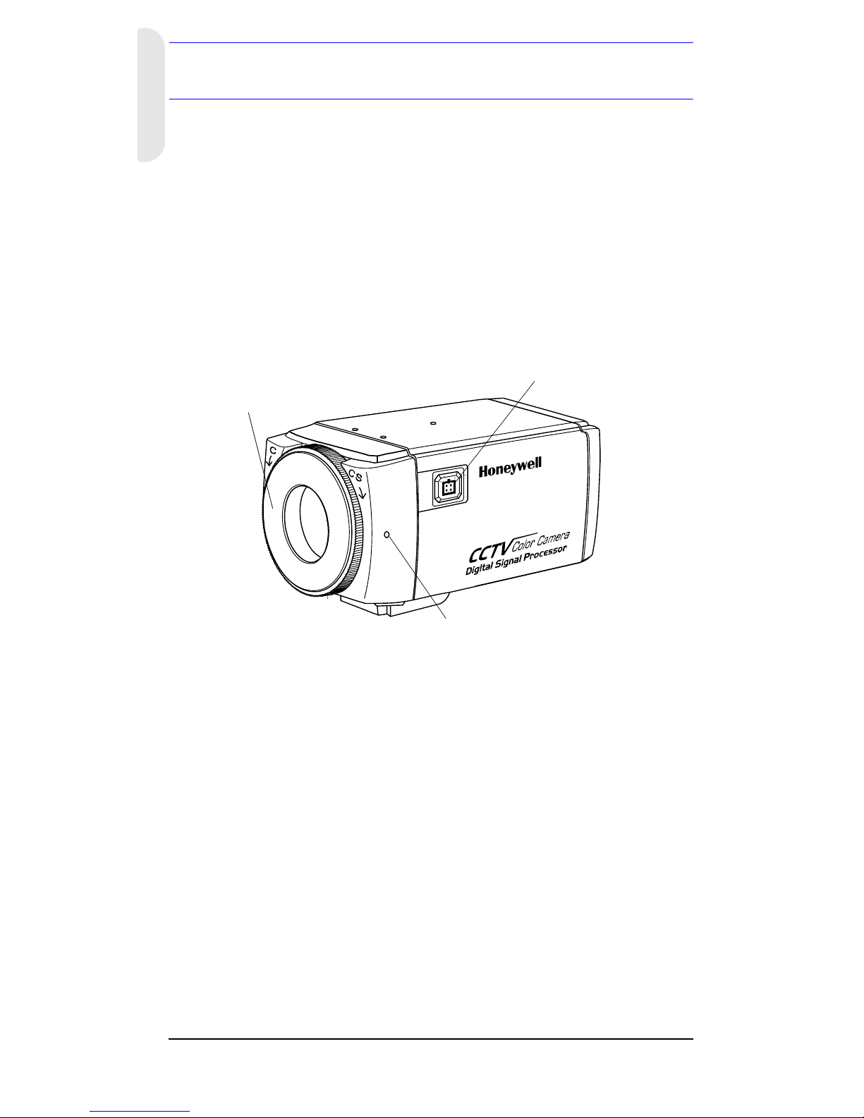
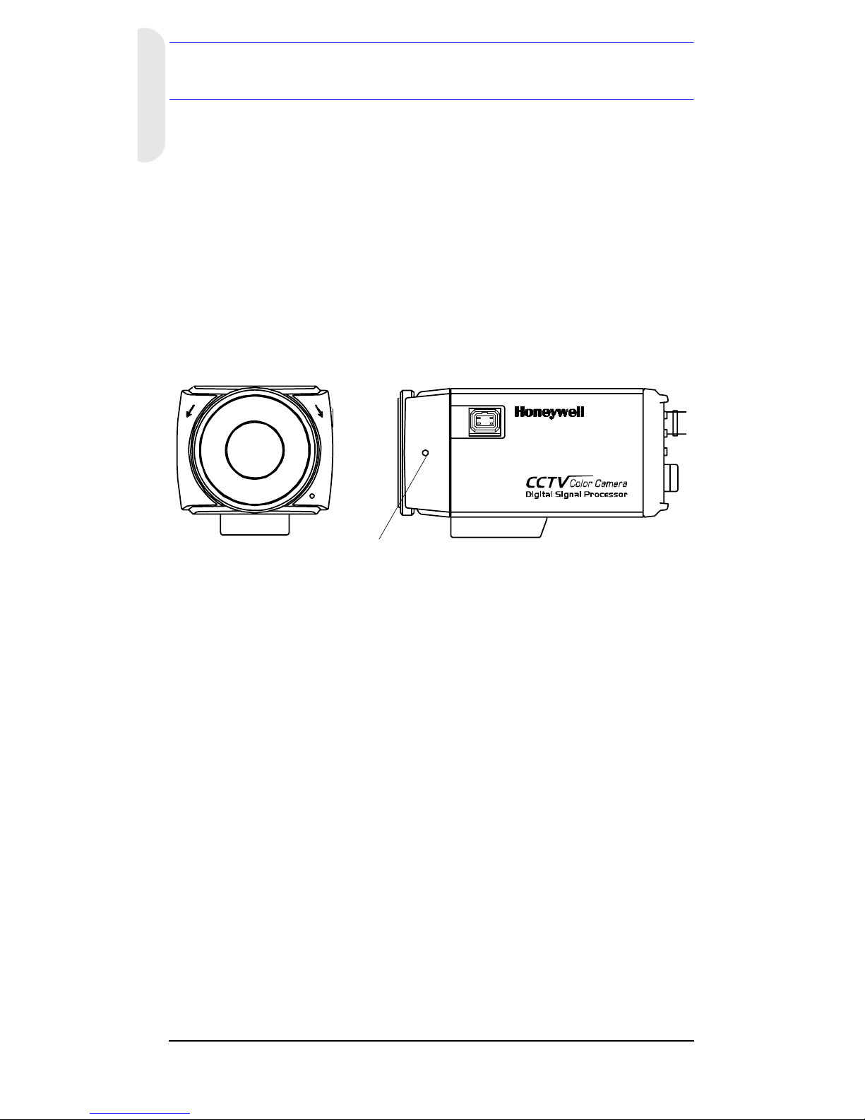
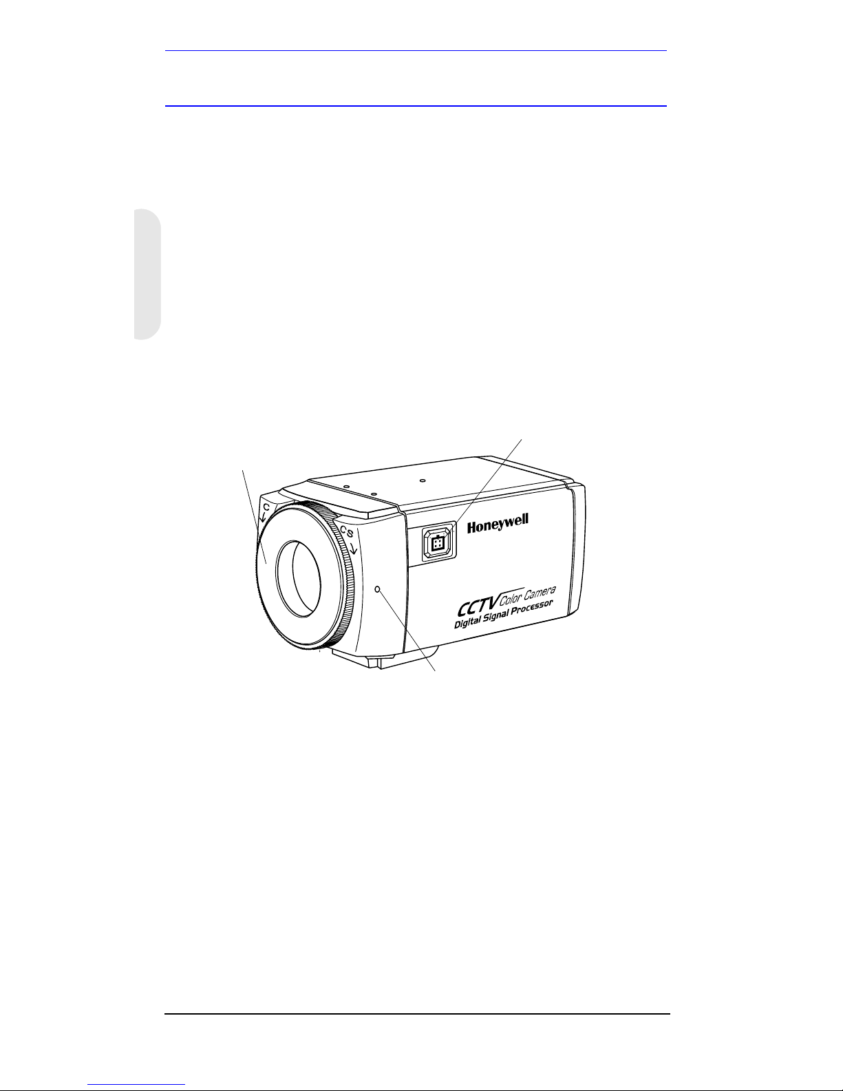
Figure 1 Camera Overview
Features
• 1/3” CCD
• C/CS adjustable lens mount adapter
• Excellent signal-to-noise ratio of more than 50 dB
• Minimum illumination:
• High Res — 0.4 lux (F1.2, 50 IRE, AGC ON)
• Standard Res — 0.2 lux (F1.2, 50 IRE, AGC ON)
• 2-way Auto Iris: Video Iris (VSD) or Direct Drive (DC) Iris
lens
Lens connector for
Auto Iris lens plug
Setscrew: loosen locking ring
with a Phillips screwdriver to
adjust mounting ring.
C/CS mount adapter:
C mount: turn
counterclockwise
CS mount: turn clockwise
Page 7

Rev 3 2 G-113077-002
01/07
English
Before You Begin
Unpack Everything
Check that the items received match those listed on the
order form and packing slip. The L-Series packing box
should include, in addition to this User Guide:
• One L-Series Color camera
• One Auto Iris lens plug
If any parts are missing or damaged, contact the dealer you
purchased the camera from or call Honeywell Customer
Service (see Contact Information on the back of this
manual).
Note You will also require a Phillips screwdriver to
complete the installation.
Please read this guide carefully
before you install the L-Series Color
camera.
Keep this guide for future reference.
Page 8
Rev 3 3 G-113077-002
01/07
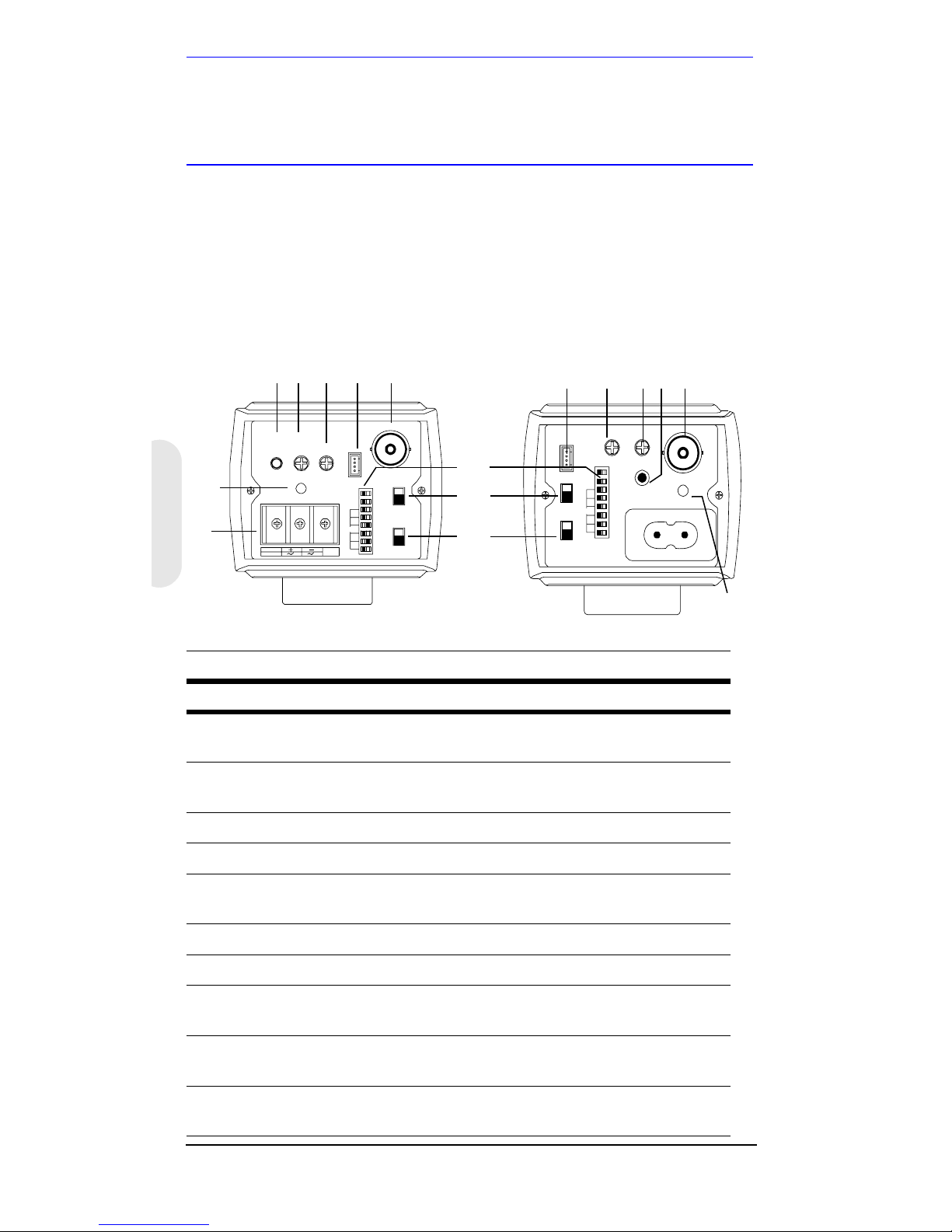
Camera Settings
Camera Functions
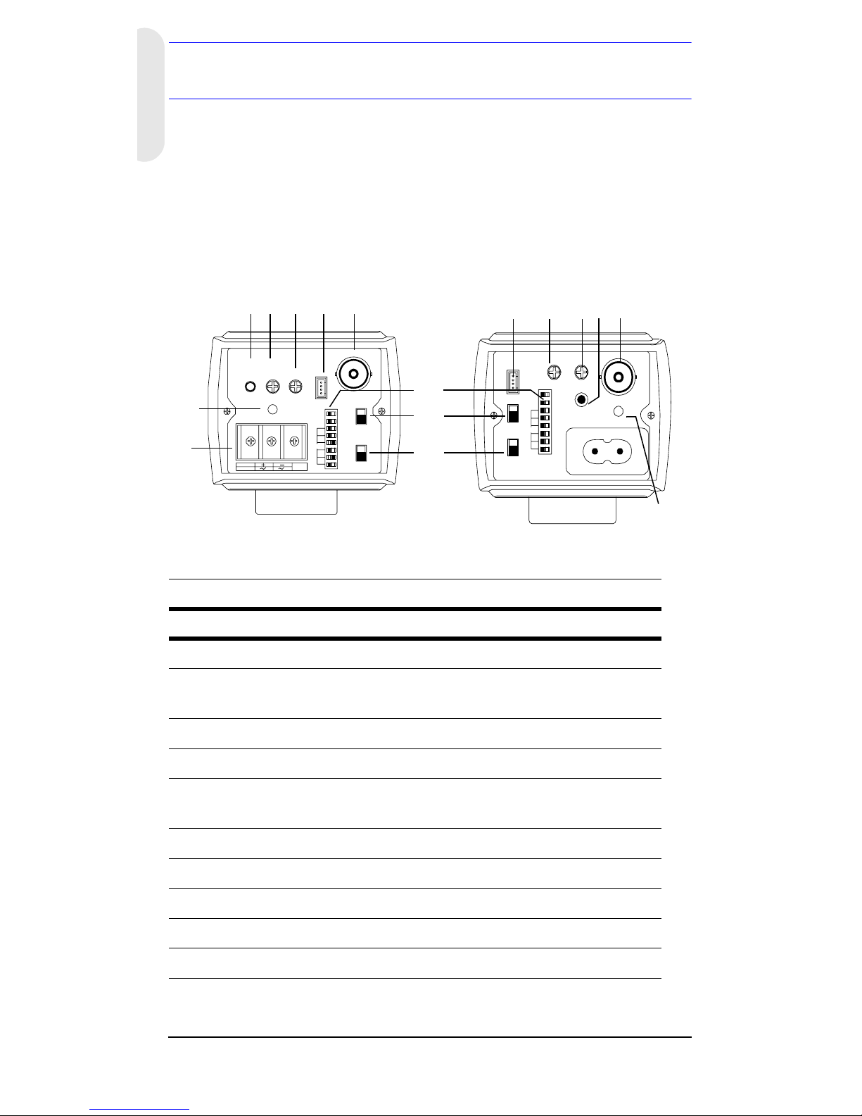
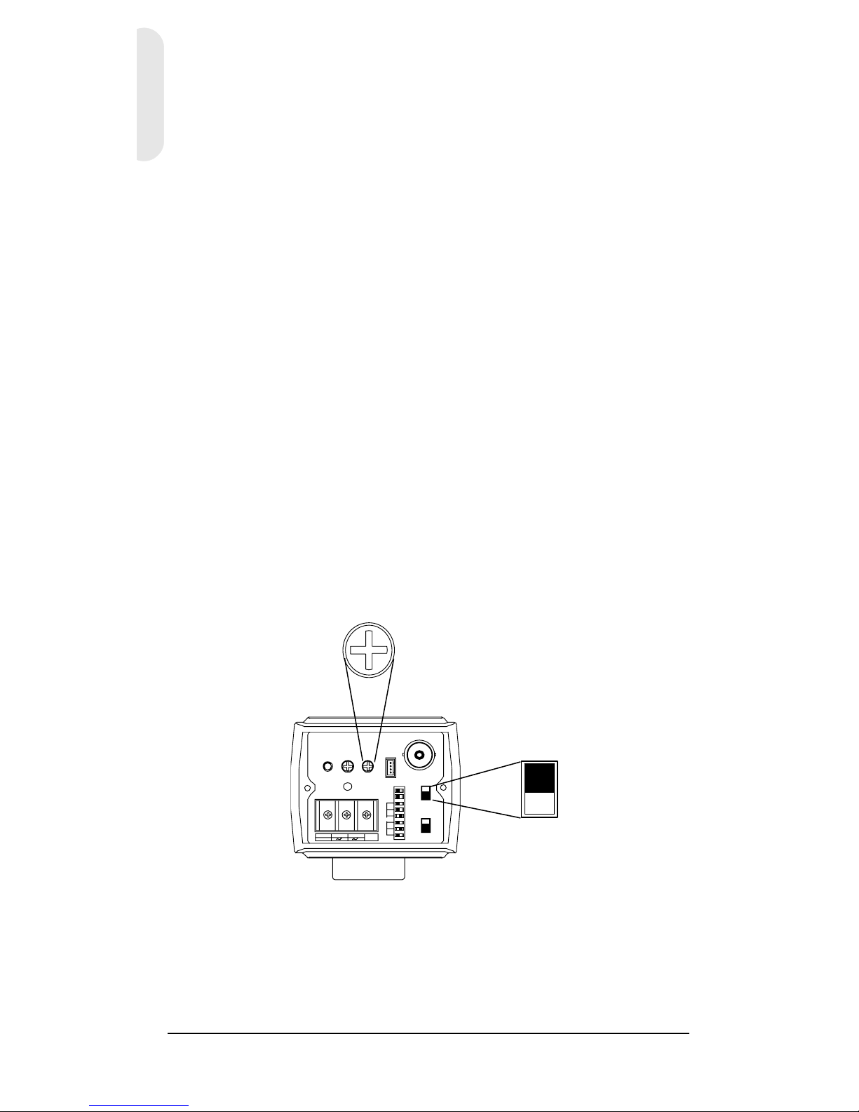
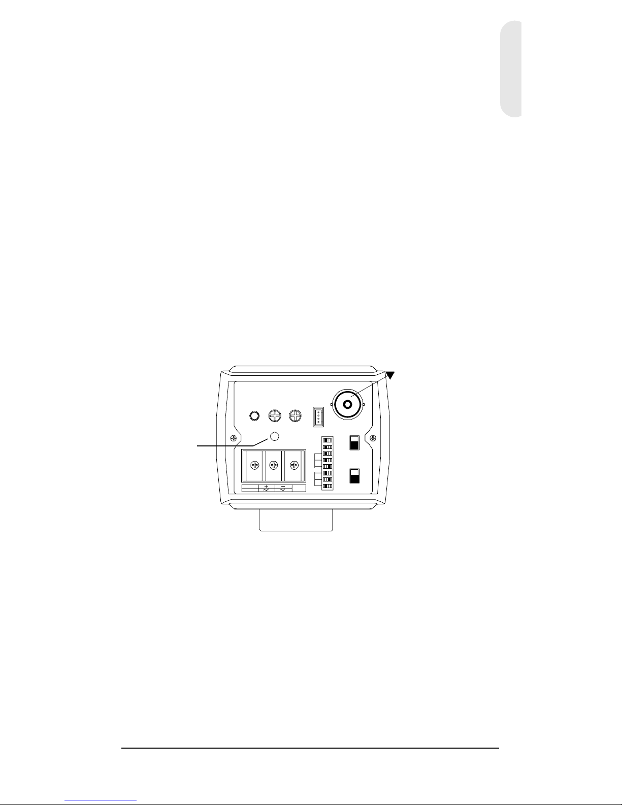
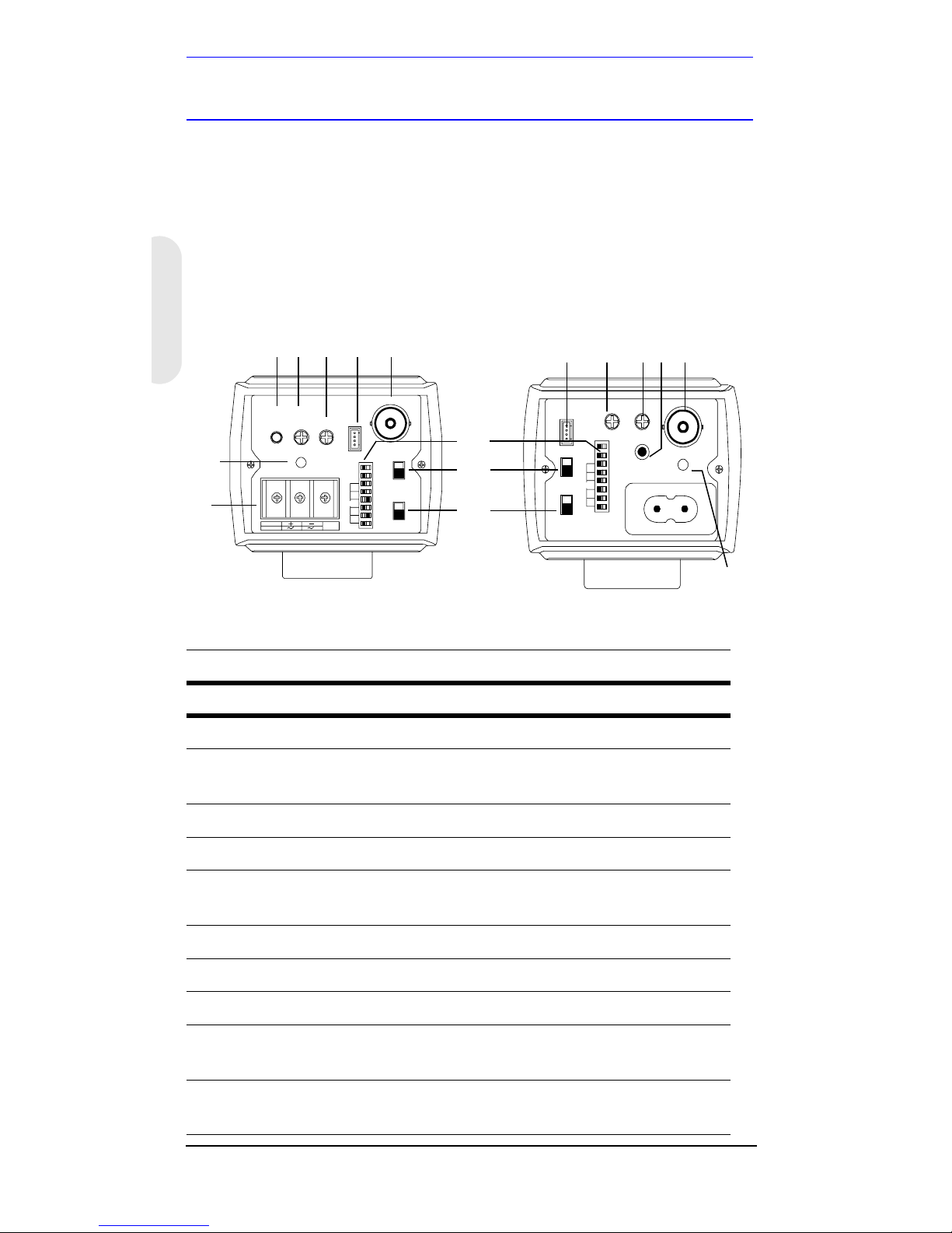
Figure 2 Camera Rear View
Legend
#Description
1
DIP switches for mode settings (see Figure 3)
2
Auto Iris Lens select switch, VSD for Video or DC for Direct
Drive
3
Sync select switch
4
Video output connector
5
Power input connector (24 VAC: 3 terminals)—Low Voltage
model only
6
Power LED indicator
7
DC Iris level adjustment, for use with DC Iris lens
8
V-Phase adjustment, for use with Line lock
9
Push Lock in White Balance (WB) mode
10
EEPROM data setting for factory use only
PUSH
LOCK
IR IS
LEVEL
PWR
L/L
IN T
VSD
DC
ME
AI
BLC
FL
AGC
WB3
WB2
WB1
EE
AES
OFF
VIDEO
~207-253VAC 50HZ
V-P H
PUSH
LOCK
IR IS
LEVEL V-PH
PWR
VIDEO
L/L
INT
VSD
DC
ME
AI
BLC
FL
AGC
WB3
WB2
WB1
EE
AES
OFF
GND
DC 12V
AC 24V
2
3
9
1
4
1087
6
5
Low Voltage
(HCC334L/X, HCC484L/X)
Mains 230V —Line Voltage
(HCC335LX, HCC485LX)
9
10 87
4
6
Page 9

Rev 3 4 G-113077-002
01/07
English
Setting Up Your Camera
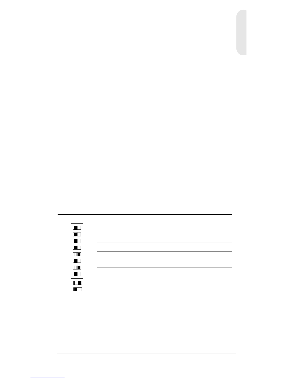
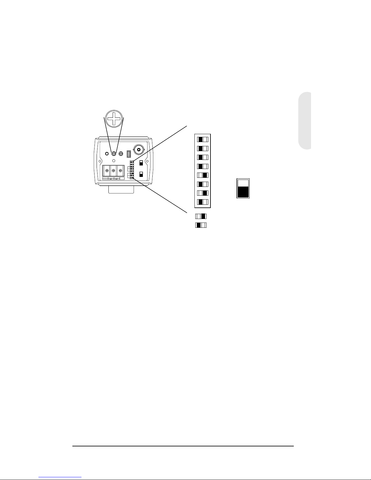
Figure 3 shows the factory set DIP switch settings.
Automatic Gain Control (AGC) and Auto White Balance
Control (AWC) are set ON.
Figure 3 Factory Set DIP Switch Settings
Selecting the Lens
Manual Lens
Set the EE/ME DIP switch on the rear of the camera (see
Figure 3) to EE. Set the AES/AI switch to AES. EE and AES
are the typical settings.
Vari-focal Auto Iris Lens
Vari-focal Auto Iris lenses (Direct Drive [DC] or Video Drive
[VSD]) are connected to the camera via a 4-pin square
socket located at the side of the camera. Set the AES/AI DIP
switch to AI. EE and AI are the typical settings.
To set a different exposure, see Exposure Mode on page 5.
Direct Drive (DC) Lens
1. Set the VSD/DC switch on the rear of the camera to DC.
Set the AES/AI DIP switch to AI.
EE
AES
OFF
OFF
OFF
OFF
OFF
OFF
ME
AI
BLC
FL
AGC
WB3
WB2
WB1
VSD
DC
IRIS
LEVEL
-+
PUSH
LOCK
IRIS
LEVEL
V-P H
PWR
VIDEO
L/L
INT
VSD
DC
ME
AI
BLC
FL
AGC
WB3
WB2
WB1
EE
AES
OFF
GND
DC 12V
AC 24V
= ON
= OFF
Page 10

Rev 3 5 G-113077-002
01/07
2. Slowly turn the LEVEL potentiometer until the picture on
the monitor is as clear as possible and is not too bright.
Video Drive (VSD) Lens
Set the VSD/DC switch on the rear of the camera (see
Figure 3) to VSD.
Exposure Mode
Automatic Exposure Mode
The Electronic Exposure feature compensates for excessive
light levels by automatically adjusting the shutter speed of
the camera. Set the EE/ME switch to EE (recommended
setting).
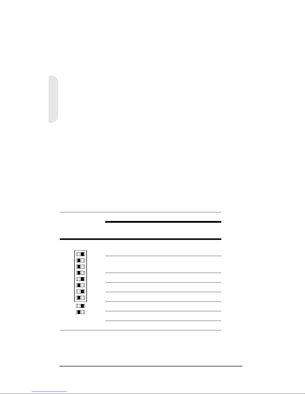
Manual Exposure Mode
Set the EE/ME switch to ME. This setting is typically used
only in machine vision applications. The table below gives
the shutter speeds for the switch settings.
Caution Before you adjust the shutter speed, it is important
that you understand how the settings can affect
the scene detail.
Switch Label
Shutter
speed(s)
FL BLC AES/AI
1/50 (PAL)
1/60 (NTSC)
OFF ON OFF
1/100 (PAL)
1/120 (NTSC)
ON ON OFF
1/250 OFF OFF OFF
1/500 ON OFF OFF
1/1000 OFF ON ON
1/2000 ON ON ON
1/4000 OFF OFF ON
1/10000 ON OFF ON
EE
AES
OFF
OFF
OFF
OFF
OFF
OFF
ME
AI
BLC
FL
AGC
WB3
WB2
WB1
= ON
= OFF
LEGEND
Page 11
Rev 3 6 G-113077-002
01/07
English
Backlight Compensation (BLC)
If there is excessive light (for example, a window exists in a
scene), the camera tries to compensate by reducing the
overall exposure, resulting in the areas surrounding the
window becoming too dark. Turn the BLC switch ON to
eliminate the silhouette effect.
Flickerless Mode (FL)
Set the FL switch to ON to remove the flicker in a picture. For
PAL models, the shutter speed is 1/100 second; for NTSC
models, the shutter speed is 1/120 second.
Automatic Gain Control (AGC)
This feature can improve picture quality when the level of
scene illumination is low. When set to OFF, the gain is 11
dB. When set to ON, the gain is 30 dB.
Auto White Balance (AWB)
Auto white balance ensures that color integrity is
maintained. To set the white balance, change the WB1,
WB2, or WB3 switches as shown in the following table.
Auto Trace White Balance (ATW)
This mode covers a range of 2800°K to 8000°K. This mode is
typically used for indoor applications.
WB1 WB2 WB3 AWB Mode
OFF OFF OFF ATW Mode
OFF ON OFF AWC Mode
OFF ON ON One Push Lock
ON OFF OFF Indoor Fixed Mode (3200°K)
ON OFF ON Fluorescent Fixed Mode
(4200°K)
ON ON OFF User Fixed Mode (4700°K)
ON ON ON Outdoor Fixed Mode (6300°K)
EE
AES
OFF
OFF
OFF
OFF
OFF
OFF
ME
AI
BLC
FL
AGC
WB3
WB2
WB1
= ON
= OFF
LEGEND
Page 12
Rev 3 7 G-113077-002
01/07
Auto White Balance Control (AWC)
This mode covers a wider range of 2000°K to 10000°K and
performs at a faster operating speed than ATW mode. This
mode is typically used for outdoor applications or where
variable lighting conditions exist.
One Push Lock
Press PUSH LOCK on the rear of the camera to calibrate the
white balance for the current scene. This mode is typically
used for scenes with constant lighting conditions.
Synchronization Selection (LL/INT)
This switch selects the synchronization mode of the camera.
When the camera is connected to an AC supply, the Line
lock (LL) mode is used to lock the camera’s frame rate to the
frequency so that each camera in the system is triggered at
the same point on the supply’s AC cycle. The default setting
is LL.
WARNING! The LL/INT switch must be set to INT
when operating from 12 VDC.
L/L
INT
V-PH
-+
PUSH
LOCK
IRIS
LEVEL
V-P H
PWR
VIDEO
L/L
INT
VSD
DC
ME
AI
BLC
FL
AGC
WB3
WB2
WB1
EE
AES
OFF
GND
DC 12V
AC 24V
Page 13

Rev 3 8 G-113077-002
01/07
English
Line Lock Phase Adjustment
Potentiometer
When the camera is in Line lock mode, it is possible to
adjust the point on the AC cycle at which the camera
triggers. This feature allows for synchronization of cameras
that are connected to different phases.
The V-PHASE adjustment potentiometer allows the line lock
phase trigger point to be adjusted by 270°. Rotating the
potentiometer clockwise advances the trigger point and
turning it counterclockwise retards the trigger point. The
factory default setting is the zero crossing point. If all
cameras in a system are on the same phase then no line
lock phase adjustment should be made.
Page 14
Rev 3 9 G-113077-002
01/07
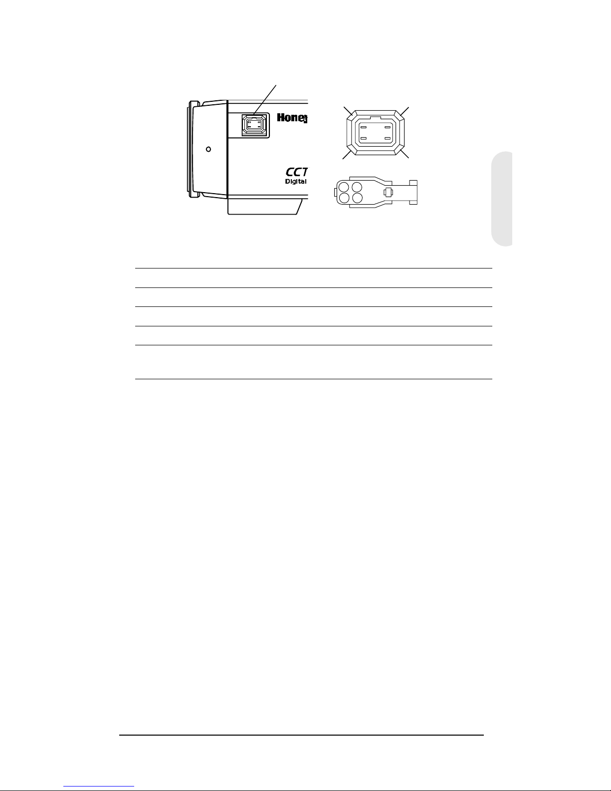
Lens Installation
Adjusting the Back Focus
The back focus adjustment is accessible at the front end of
the camera housing to adjust the back focal length or
picture focus.
The range of adjustment allows both C- and CS-mount
lenses to be used without the need for a spacer ring.
Figure 4 C/CS Mount
1. Loosen the setscrew with a Phillips screwdriver.
2. Adjust the focus ring to focus the picture.
3. Retighten the setscrew.
CCS
Setscrew
Page 15
Rev 3 10 G-113077-002
01/07
English
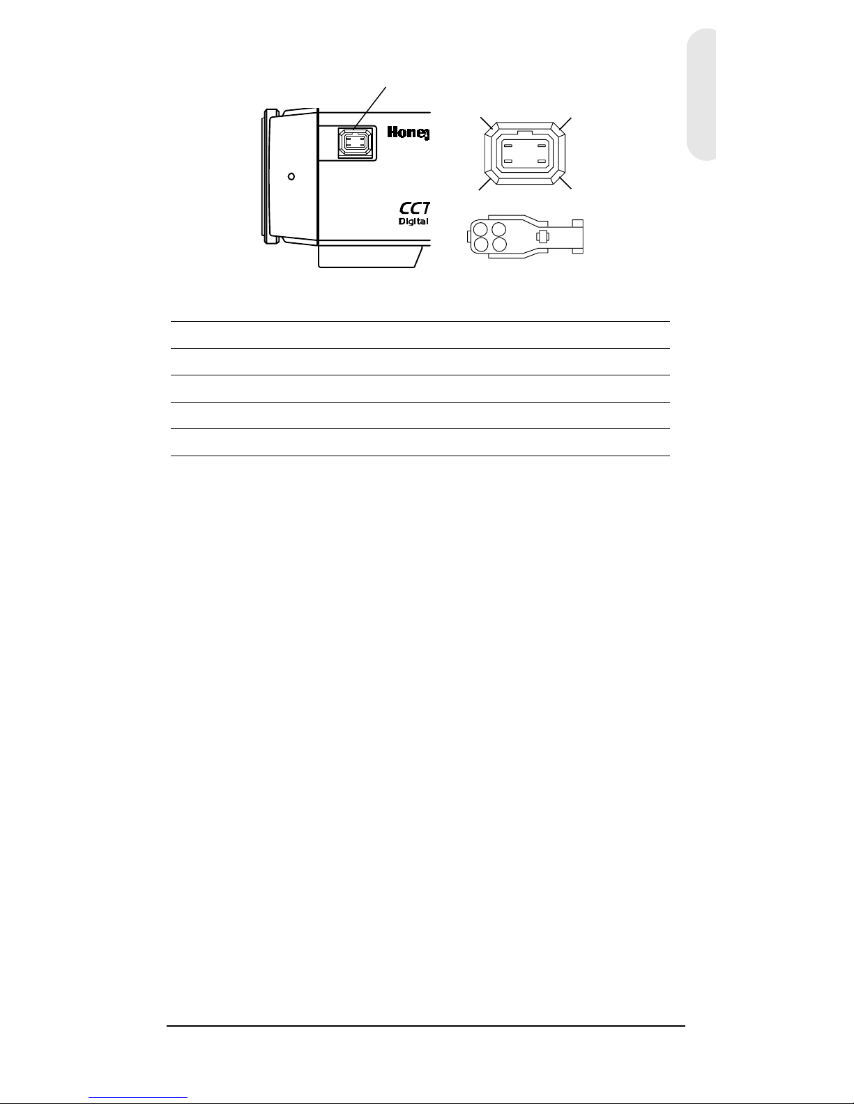
Figure 5 DC and VSD Lens Pin Definition
1
2
3
4
21
43
Pin DC (Direct Drive) lens Video (VSD) lens
1 CTRL - Power (+12V)
2CTRL + NC
3 DRV + Video Signal
4DRV - GND
Set the select switch to DC. Set the select switch to VSD.
Auto Iris lens connector
Page 16
Rev 3 11 G-113077-002
01/07
Completing the Installation
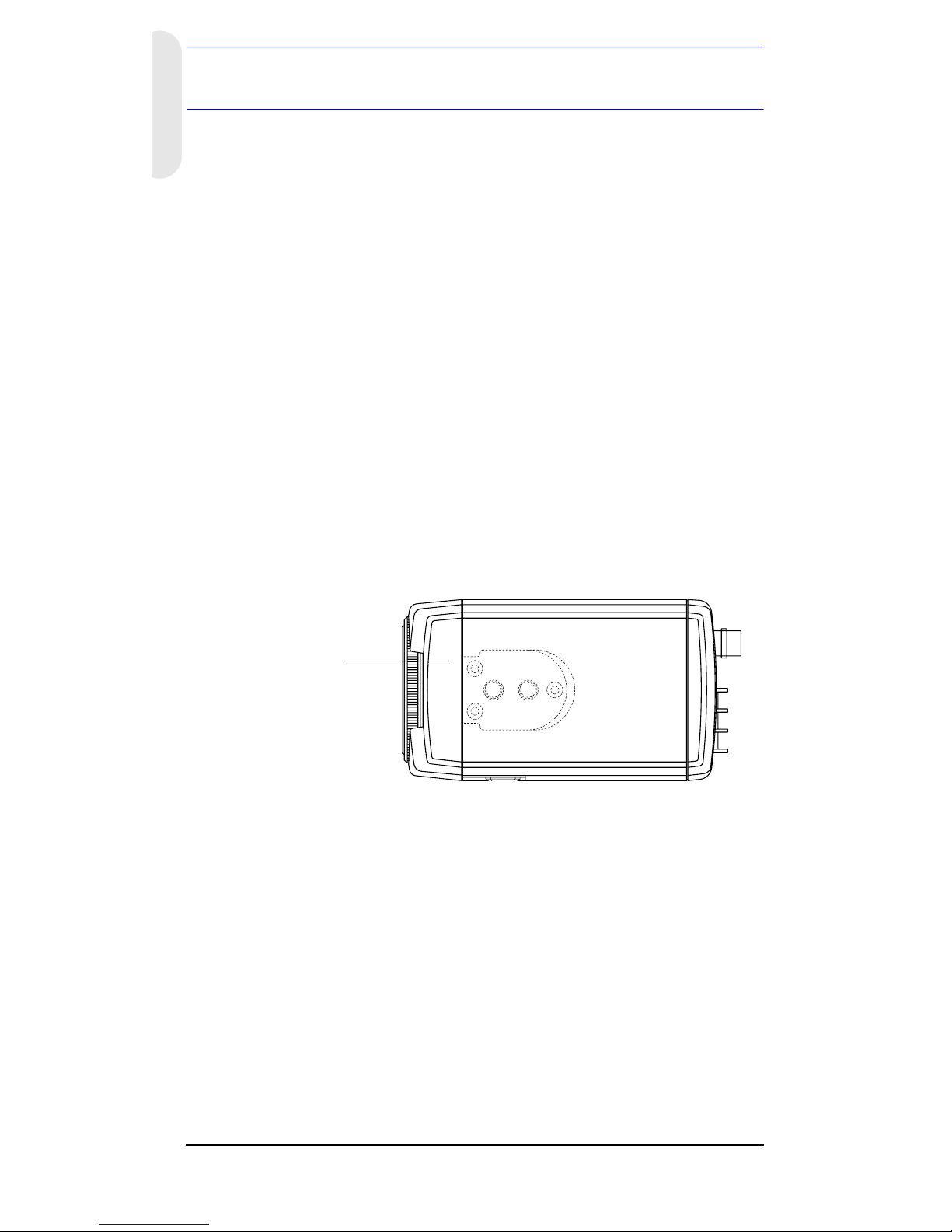
Mounting the Camera
Mounting points are provided on the top of the camera for
mounting the camera on a bracket or tripod. They are
designed to accept standard sized 1/4 x 20 mounting
screws. This bracket can be unscrewed and mounted onto
the opposite side of the camera, depending on your
application. The mounting bracket must be capable of
supporting the weight of the camera and its lens.
Note Some installation codes dictate that the mounting
bracket must be capable of supporting up to four
times the combined weight of the camera and lens.
Figure 6 Camera Mount
Unscrew 3 bracket
securing screws and
then resecure the
bracket on the other
side of the camera.
Page 17
Rev 3 12 G-113077-002
01/07
English
Connecting the Camera
1. Connect the VIDEO connector on the rear of the
camera to the video-in connector on your monitor.
2. Connect the camera to a power supply appropriate for
your installation.
HCC334L/X, HCC484L/LX: 12 VDC or 24 VAC power
supply
HCC335LX, HCC485LX: 230V power supply
3. Plug in the power supply. The power (PWR) LED
illuminates to show that the camera is receiving power.
If it does not illuminate, check the connections and the
power source.
Figure 7 Camera Connections
PUSH
LOCK
IR IS
LEVEL V-PH
PWR
VIDEO
L/L
IN T
VSD
DC
ME
AI
BLC
FL
AGC
WB3
WB2
WB1
EE
AES
OFF
GND
DC 12V
AC 24V
Monitor
Power LED
Low voltage model shown
(HCC334L/X, HCC484L/X)
Page 18

Rev 3 13 G-113077-002
01/07
Warranty and Service
Subject to the terms and conditions listed on the Product warranty,
during the warranty period Honeywell will repair or replace, at its sole
option, free of charge, any defective product returned prepaid.
In the event you have a problem with any Honeywell product, please
call Customer Service at 1.800.796.CCTV (North America only) for
assistance or to request a Return Merchandise Authorization
(RMA) number. For Europe and the United Kingdom, please contact
your Honeywell dealer.
Be sure to have the model number, serial number, and the nature of
the problem available for the technical service representative.
Prior authorization must be obtained for all returns, exchanges, or
credits. Items shipped to Honeywell without a clearly identified
Return Merchandise Authorization (RMA) number may be
refused.
Specifications
Note These specifications refer to all models, except
where otherwise noted.
HCC334L HCC334LX
HCC335LX
HCC484L HCC484LX
HCC485LX
Operational
Image Sensor: 1/3” Super HAD CCD
Video
Standard:
NTSC PAL NTSC PAL
Scanning
System:
525 lines,
2:1 interlace
625 lines,
2:1 interlace
525 lines,
2:1 interlace
625 lines,
2:1 interlace
Number of
Pixels (H x V):
510 x 492 500 x 582 768 x 494 752 x 582
Minimum
Illumination:
< 0.2 lux @ F1.2
(50 IRE, AGC ON)
< 0.4 lux @ F1.2
(50 IRE, AGC ON)
Horizontal
Resolution:
330 TVL 330 TVL 480 TVL 480 TVL
Page 19

Rev 3 14 G-113077-002
01/07
English
Video Output: 1 Vp-p @ 75 Ohms
Sync System: Internal/Line lock
S/N Ratio: > 50 dB
Auto Gain
Control (AGC):
On (30 dB)/Off (11 dB)
ALC: EE/VSD/DC
Automatic
Electronic
Shutter (AES):
1/60 1/100,000
sec
1/50 1/100,000
sec
1/60 1/100,000
sec
1/50 1/100,000
sec
Lens Mount: C/CS mount (adjustable)
White Balance
(AWB):
ATW/AWC/One Push Lock/Indoor/Outdoor/
Fluorescent/User
BLC: On/Off
Gamma: 0.45
Electrical
Input Voltage: HCC334L/LX, HCC484L/LX: 12 VDC/24 VAC
HCC335LX, HCC485LX: 230 VAC
Input Voltage
Range:
HCC334L/LX, HCC484L/LX: 11 - 16 VDC, 17 - 28 VAC
HCC335LX, HCC485LX: 230 VAC ± 10%
Power
Consumption:
HCC334L/LX, HCC484L/LX: 3.5 W (max)
HCC335LX, HCC485LX: 4.2 W (max)
Mechanical
Dimension:
(W x H x D)
HCC334L/LX, HCC484L/LX: 2.68 x 2.2 x 4.72 in. (68 x
56 x 120 mm)
HCC335LX, HCC485LX: 2.68 x 2.2 x 5.51 in. (68 x 56 x
140 mm)
Weight: HCC334L/LX, HCC484L/LX: 0.84 lb (.380 kg)
HCC335LX, HCC485LX: 0.90 lb (.410 kg)
Environmental
Temperature: Operating: 14°F to 122°F (-10°C to +50°C)
Storage: -4°F to158°F (-20°C to +70°C)
Regulatory
Emissions: FCC, CE (EN55013)
Immunity: CE (EN50130-4)
Safety: EU: 73/23/EEC LVD
HCC334L HCC334LX
HCC335LX
HCC484L HCC484LX
HCC485LX
Page 20

© 2007 Honeywell International Inc. All rights reserved. No part of this publication
may be reproduced by any means without written permission from Honeywell Video
Systems. The information in this publication is believed to be accurate in all respects.
However, Honeywell Video Systems cannot assume responsibility for any
consequences resulting from the use thereof. The information contained herein is
subject to change without notice. Revisions or new editions to this publication may
be issued to incorporate such changes.
Honeywell Video Systems
(Sede centrale)
2700 Blankenbaker Pkwy, Suite 150
Louisville, KY 40299, Stati Uniti
www.honeywellvideo.com
℡
+1.800.796.2288
Honeywell Security Australia Pty Ltd.
Unit 5, Riverside Centre
24-28 River Road West
Parramatta, NSW 2150, Australia
www.ademco.com.au
℡
+61.2.8837.9300
Honeywell Security Asia Pacific
33/F Tower A, City Center, 100 Zun Yi Road
Shanghai 200051, Cina
www.security.honeywell.com/cn
℡
+86 21.2527.4568
Honeywell Security Asia
Flat A, 16/F, CDW Building
388 Castle Peak Road
Tsuen Wan, N.T., Hong Kong
www.security.honeywell.com/hk
℡
+852.2405.2323
Honeywell Security France
Parc Gutenberg, 8, Voie La Cardon
91120, Palaiseau, Francia
www.honeywell.com/security/fr
℡
+33.01.64.53.80.40
Honeywell Security Italia SpA
Via Treviso 2 / 4
31020 San Vendemiano
Treviso, Italia
www.honeywell.com/security/it
℡
+39.04.38.36.51
Honeywell Security España
Mijancas 1. 3
a
Planta
P.Ind. Las Mercedes
28022 Madrid, Spagna
www.honeywell.com/security/es
℡
+34.902.667.800
Honeywell Video Systems
Northern Europe
Netwerk 121
1446 WV Purmerend, The Netherlands
www.SecurityHouse.nl
℡
+31.299.410.200
Honeywell Video Systems UK Ltd.
Aston Fields Road, Whitehouse Ind Est
Runcorn, Cheshire, WA7 3DL, Regno
Unito
www.honeywellvideo.com
℡
+0844 8000 235
Honeywell Security South Africa
Unit 6 Galaxy Park, 17 Galaxy Avenue
Linbro Park, P.O. Box 59904
2100 Kengray, Johannesburg
Sudafrica
www.honeywell.co.za
℡
+27.11.574.2500
Honeywell Security Deutschland
Johannes-Mauthe-Straße 14
D-72458 Albstadt, Germania
www.honeywell.com/security/de
℡
+49.74 31.8 01.0
Honeywell Security Poland
Chmielewskiego 22a, 70-028
Szczecin, Polonia
www.ultrak.pl
℡
+48.91.485.40.60
Honeywell Security Czech Republic
Havránkova 33, Brno
Dolní Heršpice, 619 00
Repubblica Ceca
www.olympo.cz
℡
+420.543.558.111
Honeywell Security Slovakia Republic
Vajnorská 142, 83104 Bratislava
Slovacchia
www.olympo.sk
℡
+421.2.444.54.660
www.honeywellvideo.com
+1.800.796.CCTV (Solo Nord America)
HVSsupport@honeywell.com
Documento
G-113077-002 01/07 Rev 3
Page 21

Document G-113077-002 – 02/07 – Rév. 3
Caméra couleur
Série L
HCC334L HCC334LX
HCC484L HCC484LX
HCC335LX
HCC485LX
Guide d’utilisation
NTSC PAL
Français
Page 22

Révisions
Édition Date Révisions
1.00 02/07 Nouveau document
1.01 09/06 Le cache-document a changé
1.02 10/06 Changement mineur
3 02/07 Mis à jour 900.0523 document
numéro de la pièce. Avertissement
supplémentaire à la page iii.
Rév. 3 ii G-113077-002
02/07
Page 23
Rév. 3 iii G-113077-002
02/07
Avertissements
L’installation et l’entretien ne doivent être effectués que par
du personnel qualifié et expérimenté, afin de respecter
toutes les normes locales et de maintenir votre garantie.
DANGER ! Les modèles 12 VDC/24 VAC requièrent
l’utilisation d’adaptateurs d’alimentation
certifiés CSA/inscrits sur la liste UL, de
classe 2, afin d’être en conformité avec
les normes de sécurité électrique.
Lorsque la prise du RÉSEAU D’ALIMENTATION ou une
prise placée sur l’appareil est utilisée comme dispositif de
déconnexion, ce dispositif doit demeuré aisément
accessible.
Déchets d'Équipements Électroniques et Électriques
(DEEE). Élimination appropriée du produit (applicable en
Union Européenne et dans d’autres pays européens
pratiquant le tri sélectif). Ce produit doit être éliminé,
à la fin de sa durée de vie utile, dans le respect des lois,
réglementations et procédures locales applicables.
Explication des symboles
graphiques
RISQUE DE CHOC
ÉLECTRIQUE :
NE PAS OUVRIR.
ATTENTION : POUR RÉDUIRE LE RISQUE DE CHOC
ÉLECTRIQUE, NE RETIREZ PAS LE COUVERCLE.
AUCUNE PIÈCE DONT L’ENTRETIEN PEUT ÊTRE
ASSURÉ PAR L’UTILISATEUR NE SE TROUVE
À L’INTÉRIEUR. CONFIEZ LA MAINTENANCE À DES
TECHNICIENS QUALIFIÉS SPÉCIALISÉS DANS
L’ENTRETIEN.
CE SYMBOLE INDIQUE QU’À
L’INTÉRIEUR DE CETTE UNITÉ
PASSE UN COURANT DE TENSION
SUFFISAMMENT ÉLEVÉE QUI RISQUE
DE PROVOQUER UN CHOC
ÉLECTRIQUE.
CE SYMBOLE INDIQUE QUE
D’IMPORTANTES INSTRUCTIONS
CONCERNANT LE FONCTIONNEMENT
ET LA MAINTENANCE ACCOMPAGNENT
CETTE UNITÉ.
ATTENTION
Français
Page 24

Rév. 3 iv G-113077-002
02/07
Déclaration de conformité FCC
Informations à l’attention de l’utilisateur : Cet
équipement a été testé et déclaré conforme aux normes
définies pour un dispositif numérique de classe A.
Conformément à l’article 15 de la Réglementation FCC, ces
normes sont conçues pour fournir une protection suffisante
contre le brouillage nuisible, lorsque l’équipement est
utilisé dans un environnement commercial. Cet
équipement génère, utilise et peut produire des émissions
radioélectriques. De plus, s’il n’est pas installé et utilisé
conformément au manuel d’utilisation, il peut provoquer un
brouillage nuisible aux communications radio. L’utilisation
de cet équipement dans une zone résidentielle peut
provoquer un brouillage nuisible, auquel cas, l’utilisateur
devra y remédier à ses propres frais.
Attention Tout changement ou modification n’ayant pas
été expressément approuvé par la partie
responsable de la conformité peut entraîner
l’annulation du droit d’exploitation de
l’équipement par l’utilisateur.
Déclaration de conformité
du fabricant
Le fabricant déclare que l’équipement fourni avec le
présent guide est conforme aux exigences essentielles de
sécurité de la directive de compatibilité électromagnétique
EMC 89/336/EEC et de la directive de basse tension
LVD 73/23 EEC, conformément aux exigences des
normes EN 55013 sur les émissions.
Page 25

Rév. 3 G-113077-002
02/07
Français
Sommaire
Introduction . . . . . . . . . . . . . . . . . . . . . . . . . . . . . . . . . . . . . 1
Caractéristiques . . . . . . . . . . . . . . . . . . . . . . . . . . . . . . . .1
Avant de commencer . . . . . . . . . . . . . . . . . . . . . . . . . . . .2
Déballage . . . . . . . . . . . . . . . . . . . . . . . . . . . . . . . . . . . . . .
Réglages de la caméra . . . . . . . . . . . . . . . . . . . . . . . . . . . 3
Fonctions de la caméra . . . . . . . . . . . . . . . . . . . . . . . . . 3
Configuration de votre caméra . . . . . . . . . . . . . . . . . . . .4
Choix de l’objectif . . . . . . . . . . . . . . . . . . . . . . . . . . . . 4
Objectif manuel . . . . . . . . . . . . . . . . . . . . . . . . . .4
Objectif à iris automatique et focale variable. . . 4
Objectif à commande directe (DC) . . . . . . . . . . 4
Objectif à commande vidéo (VSD). . . . . . . . . . . 5
Mode exposition . . . . . . . . . . . . . . . . . . . . . . . . . . . . .5
Mode exposition automatique . . . . . . . . . . . . . . . 5
Mode exposition manuel . . . . . . . . . . . . . . . . . . 5
Compensation du contre-jour (BLC) . . . . . . . . . . . . 6
Mode sans scintillement (FL) . . . . . . . . . . . . . . . . . . . 6
Contrôle automatique du gain (AGC) . . . . . . . . . . . . 6
Réglage automatique de la balance des blancs (AWB) 6
Suivi automatique de la balance des blancs (ATW) 6
Contrôle automatique de la balance
des blancs (AWC) . . . . . . . . . . . . . . . . . . . . . . . .7
Bouton-poussoir de verrouillage . . . . . . . . . . . . . 7
Sélection de synchronisation (LL/INT) . . . . . . . . . . . .7
Potentiomètre de réglage de la phase
en mode de blocage de ligne . . . . . . . . . . . . . . . . . .8
Installation de l’objectif . . . . . . . . . . . . . . . . . . . . . . . . . . . 9
Réglage du tirage optique . . . . . . . . . . . . . . . . . . . . . . . . 9
Fin de l’installation . . . . . . . . . . . . . . . . . . . . . . . . . . . . . . 11
Fixation de la caméra . . . . . . . . . . . . . . . . . . . . . . . . . . 11
Branchement de la caméra . . . . . . . . . . . . . . . . . . . . . .12
Garantie et service après-vente . . . . . . . . . . . . . . . . . . . . 13
Caractéristiques . . . . . . . . . . . . . . . . . . . . . . . . . . . . . . . . 13
Page 26
Rév. 3 1 G-113077-002
02/07
Introduction
Les caméras couleur Honeywell Série L conviennent
particulièrement pour des applications de surveillance
quotidienne. Les caméras Série L sont conçues afin de
garantir une qualité et des performances exceptionnelles
pour une utilisation quotidienne. Leurs composants prêts
à l'emploi sont conçus pour assurer des images de haute
qualité pour les applications standard et ne nécessitent
aucun réglage après leur installation.
Figure 1 Présentation de la caméra
Caractéristiques
• 1/3” CCD
• Adaptateur du support d’objectif réglable C/CS
• Excellent rapport signal-bruit de plus de 50 dB
• Éclairage minimum :
• Haute Rés — 0,4 lux (F1.2, 50 IRE, AGC ON)
• Rés standard — 0,2 lux (F1.2, 50 IRE, AGC ON)
• Iris automatique à deux positions : Objectif à iris
à commande vidéo (VSD) ou à iris à commande
directe (DC)
Connecteur d’objectif
pour fiche d’objectif
à iris automatique
Vis de serrage : serrez l’anneau de
blocage à l’aide d’un tournevis Phillips
afin de régler la bague de fixation.
Adaptateur de support C/CS :
Support C : tournez dans le sens
contraire des aiguilles d’une montre
Support CS : tournez dans le sens
des aiguilles d’une montre
Page 27

Rév. 3 2 G-113077-002
02/07
Français
Avant de commencer
Déballage
Vérifiez que les éléments reçus correspondent bien à ceux
inscrits sur le bon de commande et sur le bordereau de
marchandises. La boîte d’emballage Série L doit inclure,
en plus du présent Guide d'utilisation :
• Une caméra couleur Série L
• Une fiche d’objectif à iris automatique
Si l’une de ces pièces est manquante ou endommagée,
contactez le vendeur de la caméra ou contactez le Service
client Honeywell (voir la section Coordonnées au dos du
présent manuel).
Remarque Un tournevis Phillips sera également
nécessaire lors de l’installation.
Lire attentivement le présent guide avant
d’installer la caméra couleur Série L.
Conservez ce guide pour un usage
ultérieur.
Page 28
Rév. 3 3 G-113077-002
02/07
Réglages de la caméra
Fonctions de la caméra
Figure 2 Vue arrière de la caméra
Légende
#Description
1
Commutateurs DIP de réglage des modes (voir Figure 3)
2
Sélecteur d’objectif à iris automatique, VSD pour Vidéo ou
DC pour Commande directe
3
Sélecteur de synchronisation
4
Connecteur de sortie vidéo
5
Connecteur Alimentation (24 V CA : 3 bornes) - modèle basse
tension uniquement
6
Voyant LED d’alimentation
7
Réglage du niveau d’iris DC, à utiliser avec un objectif à iris DC
8
Réglage V-phase, à utiliser avec le mode de blocage de ligne
9
Bouton-poussoir de verrouillage en mode Balance des
blancs (WB)
10
Réglage des données de la mémoire EEPROM pour un
usage interne seulement
PUSH
LOCK
IR IS
LEVEL
PWR
L/L
IN T
VSD
DC
ME
AI
BLC
FL
AGC
WB3
WB2
WB1
EE
AES
OFF
VIDEO
~207-253VAC 50HZ
V-P H
PUSH
LOCK
IR IS
LEVEL V-PH
PWR
VIDEO
L/L
INT
VSD
DC
ME
AI
BLC
FL
AGC
WB3
WB2
WB1
EE
AES
OFF
GND
DC 12V
AC 24V
2
3
9
1
4
1087
6
5
Basse tension
(HCC334L/LX, HCC484L/LX)
Tension secteur 230 V
(HCC335LX, HCC485LX)
9
10 87
4
6
Page 29
Rév. 3 4 G-113077-002
02/07
Français
Configuration de votre caméra
Figure 3
illustre les réglages des commutateurs DIP effectués en
usine. Le contrôle automatique du gain (AGC) et le contrôle
automatique de la balance des blancs (AWC) sont réglés sur
ON
.
Figure 3 Réglages des commutateurs DIP
effectués en usine
Choix de l’objectif
Objectif manuel
Positionnez le commutateur DIP EE/ME à l'arrière de la
caméra (voir Figure 3) sur EE. Positionnez le commutateur
AES/AI sur AES. EE et AES sont les réglages types.
Objectif à iris automatique et focale variable
Les objectifs à iris automatique et à focale variable
(à commande directe [DC] ou à commande vidéo [VSD]) sont
raccordés à la caméra à l'aide d’une douille 4 pans à 4 broches
située sur le côté de la caméra. Positionnez le commutateur
AES/AI sur
AI
. EE et AI sont les réglages types.
Pour définir une exposition différente, voir
Mode
exposition page 5
Objectif à commande directe (DC)
1. Positionnez le commutateur VSD/DC à l'arrière de la
caméra sur
DC
. Positionnez le commutateur AES/AI sur AI.
EE
AES
OFF
OFF
OFF
OFF
OFF
OFF
ME
AI
BLC
FL
AGC
WB3
WB2
WB1
VSD
DC
IRIS
LEVEL
-+
PUSH
LOCK
IRIS
LEVEL
V-P H
PWR
VIDEO
L/L
INT
VSD
DC
ME
AI
BLC
FL
AGC
WB3
WB2
WB1
EE
AES
OFF
GND
DC 12V
AC 24V
= ON
= OFF
Page 30
Rév. 3 5 G-113077-002
02/07
2. Tournez lentement le potentiomètre LEVEL jusqu’à ce
que l’image sur le moniteur soit aussi nette que
possible et qu’elle ne soit pas trop brillante.
Objectif à commande vidéo (VSD)
Positionnez le commutateur VSD/DC à l’arrière de la
caméra (voir Figure 3) sur VSD.
Mode exposition
Mode exposition automatique
La fonction Exposition électronique compense des niveaux
de lumières excessifs en ajustant automatiquement la
vitesse d’obturation de la caméra. Positionnez le
commutateur EE/ME sur EE (réglage recommandé).
Mode exposition manuel
Positionnez le commutateur EE/ME sur ME. Ce réglage est
typiquement et uniquement utilisé dans des applications
de vision industrielle. Le tableau ci-dessous indique les
vitesses d’obturation pour les réglages des commutateurs.
Attention Avant de régler la vitesse d’obturation, il est
important de comprendre comment les réglages
peuvent affecter les détails de la scène.
Étiquette de commutateur
Vitesse(s)
d’obturation
FL BLC AES/AI
1/50 (PAL)
1/60 (NTSC)
OFF ON OFF
1/100 (PAL)
1/120 (NTSC)
ON ON OFF
1/250 OFF OFF OFF
1/500 ON OFF OFF
1/1000 OFF ON ON
1/2000 ON ON ON
1/4000 OFF OFF ON
1/10000 ON OFF ON
EE
AES
OFF
OFF
OFF
OFF
OFF
OFF
ME
AI
BLC
FL
AGC
WB3
WB2
WB1
= ON
= OFF
LEGEND
Page 31

Rév. 3 6 G-113077-002
02/07
Français
Compensation du contre-jour (BLC)
Si la lumière est excessive (par exemple, s’il y a une fenêtre
sur le lieu) ; la caméra essaie de compenser en réduisant
l’exposition globale, rendant les zones aux alentours de la
fenêtre trop sombres. Positionnez le commutateur BLC sur
ON pour éliminer l’effet silhouette.
Mode sans scintillement (FL)
Positionnez le commutateur FL sur ON pour effacer le
scintillement sur une image. Pour les modèles PAL, la
vitesse d’obturation est de 1/100 de seconde ; pour les
modèles NTSC, la vitesse d’obturation est de 1/120 de
seconde.
Contrôle automatique du gain (AGC)
Cette fonction peut améliorer la qualité d’image lorsque le
niveau d'éclairage du lieu est trop faible. En position OFF,
le gain est de 11 dB. En position ON, le gain est de 30 dB.
Réglage automatique de la balance des
blancs (AWB)
Le réglage automatique de la balance des blancs garantit
la fidélité de reproduction. Pour régler la balance des
blancs, modifiez la position des commutateurs WB1, WB2
ou WB3 comme indiqué dans le tableau suivant.
Suivi automatique de la balance des blancs (ATW)
Ce mode couvre une portée de 2 800°K à 8 000°K. Ce mode est
typiquement utilisé dans le cadre d’applications en extérieur.
WB1 WB2 WB3 Mode AWB
OFF OFF OFF Mode ATW
OFF ON OFF Mode AWC
OFF ON ON Bouton-poussoir de
verrouillage
ON OFF OFF Mode intérieur fixe (3200°K)
ON OFF ON Mode fluorescent fixe (4200°K)
ON ON OFF Mode utilisateur fixe (4700°K)
ON ON ON Mode extérieur fixe (6300°K)
EE
AES
OFF
OFF
OFF
OFF
OFF
OFF
ME
AI
BLC
FL
AGC
WB3
WB2
WB1
= ON
= OFF
LEGEND
Page 32

Rév. 3 7 G-113077-002
02/07
Contrôle automatique de la balance des blancs (AWC)
Ce mode couvre une portée plus large, de 2 000°K
à 10 000°K, et fonctionne à une vitesse d’ouverture plus
rapide que le mode ATW. Ce mode est typiquement utilisé
dans le cadre d’applications en extérieur ou dans des
endroits où les conditions de lumière sont variables.
Bouton-poussoir de verrouillage
Appuyez sur PUSH LOCK (BOUTON-POUSSOIR DE
VERROUILLAGE) à l'arrière de la caméra pour calibrer la
balance des blancs pour le lieu actuel. Ce mode est
typiquement utilisé pour des lieux où les conditions de
lumière sont constantes.
Sélection de synchronisation (LL/INT)
Ce commutateur permet de sélectionner le mode de
synchronisation de la caméra. Lorsque la caméra est
raccordée à une alimentation alternative, le mode de
blocage de ligne (LL) est utilisé pour verrouiller la cadence
de prise de vue de la caméra sur la fréquence afin que
chaque caméra du système se déclenche au même
moment sur le cycle d’alimentation alternative. Le réglage
par défaut est LL.
DANGER ! Le commutateur LL/INT doit être réglé sur
INT lorsqu’il fonctionne sous 12 V CC.
L/L
INT
V-PH
-+
PUSH
LOCK
IRIS
LEVEL V-PH
PWR
VIDEO
L/L
INT
VSD
DC
ME
AI
BLC
FL
AGC
WB3
WB2
WB1
EE
AES
OFF
GND
DC 12V
AC 24V
Page 33

Rév. 3 8 G-113077-002
02/07
Français
Potentiomètre de réglage de la phase en
mode de blocage de ligne
Lorsque la caméra est en mode de blocage de ligne, il est
possible de régler le point sur cycle d’alimentation
alternative sur lequel la caméra se déclenche. Cette
fonction permet la synchronisation des caméras qui sont
connectées aux différentes phases.
Le potentiomètre de réglage V-PHASE permet de régler de
270° le point de déclenchement de la phase de blocage de
ligne. Le point de déclenchement est avancé en faisant
tourner le potentiomètre dans le sens des aiguilles d’une
montre, et retardé en le faisant tourner dans le sens
contraire des aiguilles d’une montre. Le réglage d'usine
par défaut est le point de croisement zéro. Si toutes les
caméras d’un système sont sur la même phase, aucun
réglage de phase de blocage de ligne ne doit être effectué.
Page 34

Rév. 3 9 G-113077-002
02/07
Installation de l’objectif
Réglage du tirage optique
Le réglage du tirage optique est accessible sur l’extrémité
avant du boîtier de la caméra et permet de régler la
longueur focale arrière ou de procéder à la mise au point
de l’image.
La portée de réglage permet l’utilisation des deux supports
d’objectifs C et CS sans avoir recours à une bague
d’espacement.
Figure 4 Support C/CS
1. Desserrez la vis de blocage à l’aide d’un
tournevis Phillips.
2. Réglez la bague de variation de la focale afin
d’effectuer la mise au point de l’image.
3. Resserrez la vis de blocage.
CCS
Vis de serrage
Page 35
Rév. 3 10 G-113077-002
02/07
Français
Figure 5 Définition des broches d’objectifs DC
et VSD
1
2
3
4
21
43
Broche Objectif à commande
directe (DC)
Objectif à commande
vidéo (VSD)
1 CTRL - Alimentation (+12V)
2CTRL + NC
3 DRV + Signal vidéo
4DRV - GND
Positionnez le sélecteur
sur DC
Positionnez le sélecteur
sur VSD
Connecteur d’objectif à iris automatique
Page 36

Rév. 3 11 G-113077-002
02/07
Fin de l’installation
Fixation de la caméra
Les points de fixation se trouvent sur la partie supérieure
de la caméra pour fixer la caméra sur un support ou un
trépied. Ils sont conçus pour supporter des vis de fixation
de taille standardisée 1/4 x 20. Ce support peut être
dévissé et fixé sur le côté opposé de la caméra, selon son
application. Le support de fixation doit être capable de
supporter le poids de la caméra et de son objectif.
Remarque Certains manuels d’installation mentionnent
que le support de fixation doit être capable
de supporter jusqu'à quatre fois le poids de
la caméra et de l’objectif réunis.
Figure 6 Support de la caméra
Dévissez les trois vis
de fixation du support,
puis fixez à nouveau le
support sur l’autre
côté de la caméra.
Page 37

Rév. 3 12 G-113077-002
02/07
Français
Branchement de la caméra
1. Raccordez le connecteur VIDEO à l’arrière de la
caméra au connecteur d’entrée vidéo de votre
moniteur.
2. Branchez la caméra sur une alimentation électrique
adaptée à votre installation.
HCC334L/LX, HCC484L/LX : alimentation 12 V CC
ou 24 V CA.
HCC335LX, HCC485LX : alimentation 230 V
3. Branchez l’alimentation électrique. Le voyant LED
d’alimentation (PWR) s’allume pour indiquer que la
caméra reçoit de l’électricité. Si le voyant ne s’allume
pas, vérifiez les branchements et la source
d’alimentation.
Figure 7 Branchements de la caméra
PUSH
LOCK
IR IS
LEVEL V-PH
PWR
VIDEO
L/L
IN T
VSD
DC
ME
AI
BLC
FL
AGC
WB3
WB2
WB1
EE
AES
OFF
GND
DC 12V
AC 24V
Moniteur
Voyant LED
d’alimentation
Modèle basse tension représenté
(HCC334L/LX, HCC484L/LX)
Page 38

Rév. 3 13 G-113077-002
02/07
Garantie et service après-vente
Soumise aux termes et conditions énumérées sur la garantie du
produit, Honeywell réparera ou remplacera, pendant la période de
garantie, selon son propre choix, sans frais supplémentaire, tout
produit défectueux prépayé et retourné.
En cas de problème avec un produit Honeywell, veuillez contacter
le Service client au 1 800 796 CCTV (Amérique du Nord
uniquement) pour recevoir une assistance ou demander un numéro
d’
Autorisation de Retour de Marchandise (ARM)
. Pour l’Europe
et le Royaume Uni, veuillez contacter votre distributeur Honeywell.
Veuillez vous assurer de disposer du numéro de modèle, du
numéro de série et de la nature du problème afin de les fournir au
représentant du service technique.
Vous
devez
vous procurer une autorisation préalable pour tout
retour, échange ou crédit.
Les articles expédiés à Honeywell
sans numéro d’Autorisation de Retour de Marchandise
pourront être refusés.
.
Caractéristiques
Remarque Ces caractéristiques font référence à tous les
modèles, sauf mention contraire.
HCC334L HCC334LX
HCC335LX
HCC484L HCC484LX
HCC485LX
Opérationnel
Capteur d’image
:
1/3” Super HAD CCD
Standard vidéo : NTSC PAL NTSC PAL
Système de
balayage :
525 lignes,
entrelacement 2:1
625 lignes,
entrelacement 2:1
525 lignes,
entrelacement 2:1
625 lignes,
entrelacement 2:1
Nombre de pixels
(H x V) :
510 x 492 500 x 582 768 x 494 752 x 582
Éclairage
minimum :
< 0,2 lux @ F1.2
(50 IRE, AGC ON)
< 0,4 lux @ F1.2
(50 IRE, AGC ON)
Page 39

Rév. 3 14 G-113077-002
02/07
Français
Résolution
horizontale :
330 TVL 330 TVL 480 TVL 480 TVL
Sortie vidéo : 1 Vp-p @ 75 Ohms
Système de
synchronisation :
Interne/Blocage de ligne
Ratio S/N : > 50 dB
Contrôle
automatique du
gain (AGC) :
On (30 dB)/Off (11 dB)
ALC : EE/VSD/DC
Obturation
électronique
automatique
(AES) :
1/60 1/100 000
de seconde
1/50 1/100 000
de seconde
1/60 1/100 000
de seconde
1/50 1/100 000
de seconde
Support de
l’objectif :
Support (réglable) C/CS :
Balance des
blancs (AWB) :
ATW/AWC/Bouton-poussoir de verrouillage/Intérieur/
Extérieur/Fluorescent/Utilisateur
BLC : On/Off
Gamma : 0.45
Branchement électrique
Tension d’entrée
:
HCC334L/LX, HCC484L/LX : 12 V CC/24 V CA
HCC335LX, HCC485LX : 230 V CA
Plage des
tensions d’entrée
:
HCC334L/LX, HCC484L/LX : 11 - 16 V CC, 17 - 28 V CA
HCC335LX, HCC485LX : 230 V CA ± 10 %
Consommation :
HCC334L/LX, HCC484L/LX: 3.5 W (max)
HCC335LX, HCC485LX: 4.2 W (max)
Mécanique
Dimensions :
(L x H x P)
HCC334L/LX, HCC484L/LX : 68 x 56 x 120 mm
HCC335LX, HCC485LX : 68 x 56 x 140 mm
Poids : HCC334L/LX, HCC484L/LX : 0,380 kg
HCC335LX, HCC485LX : 0,410 kg
Environnement
Température : Fonctionnement : -10°C à +50°C
Stockage : -20°C à +70°C
Réglementation
Émissions : FCC, CE (EN55013)
Immunité : CE (EN50130-4)
Sécurité : UE : 73/23/EEC LVD
HCC334L HCC334LX
HCC335LX
HCC484L HCC484LX
HCC485LX
Page 40

© 2007 Honeywell International Inc. Tous droits réservés. Ce document ne peut être
reproduit, en totalité ou en partie, par n’importe quel moyen que ce soit, sans
autorisation écrite provenant de Honeywell Video Systems. Les informations
contenues dans cette publication sont considérées comme exactes à tous les
égards. Cependant, Honeywell Video Systems n’est en aucun cas responsable des
conséquences résultant de son utilisation. Les informations ci-incluses sont sujettes
à modification sans préavis. Des révisions ou de nouvelles éditions de la présente
publication peuvent être diffusées afin d’intégrer de telles modifications.
www.honeywellvideo.com
+1.800.796.CCTV (Amérique du Nord uniquement)
HVSsupport@honeywell.com
Document G-113077-002 02/07 Rév. 3
Honeywell Video Systems (Siège)
2700 Blankenbaker Pkwy, Suite 150
Louisville, KY 40299, États-Unis
www.honeywellvideo.com
℡
+1.800.796.2288
Honeywell Security Australia Pty Ltd.
Unit 5, Riverside Centre
24-28 River Road West
Parramatta, NSW 2150, Australie
www.ademco.com.au
℡
+61.2.8837.9300
Honeywell Security Asia Pacific
33/F Tower A, City Center, 100 Zun Yi
Road
Shanghai 200051, Chine
www.security.honeywell.com/cn
℡
+86 21.2527.4568
Honeywell Security Asia
Flat A, 16/F, CDW Building
388 Castle Peak Road
Tsuen Wan, N.T., Hong Kong
www.security.honeywell.com/hk
℡
+852.2405.2323
Honeywell Security France
Parc Gutenberg, 8, Voie La Cardon
91120, Palaiseau, France
www.honeywell.com/security/fr
℡
+33.01.64.53.80.40
Honeywell Security Italia SpA
Via Treviso 2 / 4
31020 San Vendemiano
Treviso, Italie
www.honeywell.com/security/it
℡
+39.04.38.36.51
Honeywell Security España
Mijancas 1. 3
a
Planta
P.Ind. Las Mercedes
28022 Madrid, Espagne
www.honeywell.com/security/es
℡
+34.902.667.800
Honeywell Video Systems
Northern Europe
Netwerk 121
1446 WV Purmerend, Pays-Bas
www.SecurityHouse.nl
℡
+31.299.410.200
Honeywell Video Systems UK Ltd.
Aston Fields Road, Whitehouse Ind Est
Runcorn, Cheshire, WA7 3DL,
Royaume-Uni
www.honeywellvideo.com
℡
+0844 8000 235
Honeywell Security South Africa
Unit 6 Galaxy Park, 17 Galaxy Avenue
Linbro Park, P.O. Box 59904
2100 Kengray, Johannesburg
Afrique du Sud
www.honeywell.co.za
℡
+27.11.574.2500
Honeywell Security Deutschland
Johannes-Mauthe-Straße 14
D-72458 Albstadt, Allemagne
www.honeywell.com/security/de
℡
+49.74 31.8 01.0
Honeywell Security Poland
Chmielewskiego 22a, 70-028
Szczecin, Polska
www.ultrak.pl
℡
+48.91.485.40.60
Honeywell Security Czech Republic
Havránkova 33, Brno
Dolní Heršpice, 619 00
République Tchèque
www.olympo.cz
℡
+420.543.558.111
Honeywell Security Slovakia Republic
Vajnorská 142, 83104 Bratislava
Slovaquie
www.olympo.sk
℡
+421.2.444.54.660
Page 41

Documento G-113077-002 – 02/07 – Rev. 3
Cámara de color
L-Series
HCC334L HCC334LX
HCC484L HCC484LX
HCC335LX
HCC485LX
Guía del usuario
NTSC PAL
Español
Page 42

Revisiones
Elaborado Fecha Revisiones
1.00 02/07 Nuevo documento
1.01 09/06 La cubierta de documento cambió.
1.02 10/06 Cambio de menor importancia
3 02/07 Documento actualizado número de
pieza; Advertencia agregada a la
página iii.
Rev. 3 ii G-113077-002
02/07
Page 43

Rev. 3 iii G-113077-002
02/07
Advertencias
La instalación y el mantenimiento deben ser realizados por
personal experimentado y especializado para cumplir con
las normas locales y mantener la cobertura de la garantía.
ADVERTENCIA Es obligatorio que los modelos de 12
V CC/24 V CA utilicen adaptadores de
corriente de Clase 2 reconocidos por
UL o aprobados por CSA, para
garantizar el cumplimiento de las
normas de seguridad eléctrica.
Aunque se utilice el enchufe o clema de conexión a red
como dispositivo de desconexión, debe instalarse un
dispositivo de desconexión que permita cortar la
alimentación.
WEEE (Residuos de equipos eléctricos y electrónicos).
Eliminación correcta de este producto (aplicable en la
Unión Europea y otros países europeos con diferentes
sistemas de recogida). Se debe eliminar este producto al
final de su vida útil conforme a las normas, normativas
y procedimientos locales aplicables.
Explicación de los símbolos
gráficos
RIESGO DE DESCARGA
ELÉCTRICA.
NO ABRIR
PRECAUCIÓN: PARA REDUCIR EL RIESGO DE DESCARGAS
ELÉCTRICAS, NO RETIRE LA CUBIERTA.
NO HAY PIEZAS EN EL INTERIOR QUE PUEDA
MANIPULAR EL USUARIO.
ES CONVENIENTE DEJAR LAS FUNCIONES DE
MANTENIMIENTO AL PERSONAL ESPECIALIZADO
ESTE SÍMBOLO INDICA LA
EXISTENCIA DE TENSIÓN
PELIGROSA EN LA UNIDAD
Y PODRÍA SUPONER UN RIESGO
DE DESCARGA ELÉCTRICA.
ESTE SÍMBOLO INDICA QUE SE
INCLUYEN INSTRUCCIONES DE
FUNCIONAMIENTO Y
MANTENIMIENTO IMPORTANTES
CON ESTA UNIDAD.
PRECAUCIÓN
Español
Page 44

Rev. 3 iv G-113077-002
02/07
Declaración de conformidad con
las Normas FCC
Información dirigida al usuario: Este dispositivo ha sido
sometido a pruebas y ha demostrado cumplir con los
límites establecidos para un dispositivo digital de clase A.
Conforme al Apartado 15 de las Normas FCC, estos límites
han sido diseñados para proporcionar una protección
razonable frente a las interferencias perjudiciales durante
su uso en un entorno comercial. Este equipo genera, utiliza
y puede emitir energía de radiofrecuencia y, si no se instala
y utiliza según el manual de instrucciones, puede provocar
interferencias en las comunicaciones por radio. Es
probable que el uso de este dispositivo en una zona
residencial provoque interferencias perjudiciales. En este
caso, el usuario deberá corregirlas y asumir los costes.
Precaución Cualquier modificación realizada sin la
aprobación expresa de la parte responsable
del cumplimiento de las normas, podría
anular el derecho del usuario a utilizar
el equipo.
Declaración de conformidad del
fabricante
El fabricante declara que el equipo suministrado con esta
guía cumple con los requisitos básicos de protección, con
arreglo a la Directiva 89/336/CEE sobre compatibilidad
electromagnética y la Directiva 73/23/CEE sobre baja
tensión, conforme a los requisitos de los estándares
EN 55013 para emisiones.
Page 45

Rev. 3 G-113077-002
02/07
Español
Contenido
Introducción . . . . . . . . . . . . . . . . . . . . . . . . . . . . . . . . . . . . 1
Características . . . . . . . . . . . . . . . . . . . . . . . . . . . . . . . . 1
Antes de comenzar . . . . . . . . . . . . . . . . . . . . . . . . . . . . .2
Desembalaje de todo . . . . . . . . . . . . . . . . . . . . . . . . . . . 2
Valores de configuración de la cámara . . . . . . . . . . . . . . . 3
Funciones de la cámara . . . . . . . . . . . . . . . . . . . . . . . . .3
Instalación de la cámara. . . . . . . . . . . . . . . . . . . . . . . . . 4
Selección de lentes. . . . . . . . . . . . . . . . . . . . . . . . . . 4
Lentes manuales . . . . . . . . . . . . . . . . . . . . . . . . . 4
Lentes autoiris varifocales . . . . . . . . . . . . . . . . . .4
Lentes de control directo (DC) . . . . . . . . . . . . . .4
Lente de tipo vídeo (VSD) . . . . . . . . . . . . . . . . . 5
Modo de exposición . . . . . . . . . . . . . . . . . . . . . . . . . 5
Modo de exposición automático . . . . . . . . . . . . 5
Modo de exposición manual . . . . . . . . . . . . . . . 5
Compensación de contraluz (BLC) . . . . . . . . . . . . . .6
Modo sin parpadeos (FL) . . . . . . . . . . . . . . . . . . . . . 6
Control automático de ganancia (AGC) . . . . . . . . . . 6
Balance automático de blancos (AWB) . . . . . . . . . . 6
Detección automática de balance de blancos (ATW) 7
Control automático de balance de blancos (AWC) 7
Bloqueo de una pulsación . . . . . . . . . . . . . . . . .7
Selección de sincronización (LL/INT) . . . . . . . . . . . .7
Potenciómetro de ajuste de la fase Line Lock . . . . . .8
Instalación de la lente . . . . . . . . . . . . . . . . . . . . . . . . . . . . . 9
Ajuste del enfoque posterior . . . . . . . . . . . . . . . . . . . . . 9
Final de la instalación . . . . . . . . . . . . . . . . . . . . . . . . . . . 11
Montaje de la cámara . . . . . . . . . . . . . . . . . . . . . . . . . .11
Conexión de la cámara . . . . . . . . . . . . . . . . . . . . . . . . .12
Garantía y servicio. . . . . . . . . . . . . . . . . . . . . . . . . . . . . . 13
Especificaciones . . . . . . . . . . . . . . . . . . . . . . . . . . . . . . . . 13
Page 46

Rev. 3 1 G-113077-002
02/07
Introducción
Las cámaras de color L-Series de Honeywell son perfectas
para su uso en aplicaciones de vigilancia diarias. Las
cámaras L-Series están diseñadas para ofrecer un valor
y rendimiento excepcionales en su uso diario. El conjunto
de características de serie ha sido diseñado para tomar
imágenes de alta calidad en aplicaciones estándar
y apenas requiere ajustes una vez instalado.
Figura 1 Descripción general de la cámara
Características
• CCD de tipo 1/3”
• Adaptador para el montaje de la lente ajustable a C/CS
• Excelente relación señal-ruido superior a 50 dB
• Iluminación mínima:
• Alta res.: 0,4 lux (F1.2, 50 IRE, AGC activado)
• Res. Estándar: 0,2 lux (F1.2, 50 IRE, AGC
activado)
• Lente autoiris varifocal: tipo vídeo (VSD) o de control
directo (DC)
Conector de lente para
conectar una lente
autoiris
Tornillo de fijación: afloje el anillo de
fijación con un destornillador Phillips
para ajustar la rosca de montaje
Adaptador de montaje C/CS
Montaje C: girar en el sentido
contrario a las agujas del reloj
Montaje CS: girar en el sentido
de las agujas del reloj
Page 47

Rev. 3 2 G-113077-002
02/07
Español
Antes de comenzar
Desembalaje de todo
Compruebe que los artículos recibidos coinciden con los
que figuran en el pedido y el comprobante de la caja.
La caja de la cámara L-Series debería incluir además de
esta guía del usuario:
• Una cámara de color L-Series
• Un conector para la lente autoiris
Si faltara algún componente o estuviera dañado, póngase
en contacto con el distribuidor donde adquirió la cámara
o llame al servicio de atención al cliente de Honeywell
(consulte el apartado Información de contacto al final de
este manual).
Nota Necesitará también un destornillador Phillips para
terminar la instalación.
Lea esta guía con atención antes de
instalar la cámara de color L-Series.
Guarde esta guía para futuras
consultas.
Page 48
Rev. 3 3 G-113077-002
02/07
Valores de configuración de
la cámara
Funciones de la cámara
Figura 2 Vista posterior de la cámara
Leyenda
Nº Descripción
1
Conmutadores DIP para la configuración de modo
(véase Figura 3)
2
Conmutador de selección de lentes autoiris, VSD para video
o DC para control directo
3
Conmutador de selección de sincronización
4
Conector de salida de vídeo
5
Conector de entrada de alimentación
(24 V CA: 3 terminales)—Sólo modelo de bajo voltaje
6
Indicador luminoso de alimentación
7
Ajuste de nivel de iris DC, para utilizar con lentes iris DC
8
Ajuste de la fase V, para utilizar con la sincronización por fase
de red (line lock)
9
Push Lock (bloqueo de pulsación) en el modo de balance de
blancos (WB)
10
Configuración de datos en el EEPROM, para uso de fábrica
únicamente
PUSH
LOCK
IR IS
LEVEL
PWR
L/L
IN T
VSD
DC
ME
AI
BLC
FL
AGC
WB3
WB2
WB1
EE
AES
OFF
VIDEO
~207-253VAC 50HZ
V-P H
PUSH
LOCK
IR IS
LEVEL V-PH
PWR
VIDEO
L/L
INT
VSD
DC
ME
AI
BLC
FL
AGC
WB3
WB2
WB1
EE
AES
OFF
GND
DC 12V
AC 24V
2
3
9
1
4
1087
6
5
Bajo voltaje
(HCC334L/LX, HCC484L/LX)
Línea de voltaje principal
(HCC335LX, HCC485LX)
9
10 87
4
6
Page 49

Rev. 3 4 G-113077-002
02/07
Español
Instalación de la cámara
La Figura 3 muestra los valores del conmutador DIP
definidos en fábrica. El control automático de ganancia
(AGC) y el control automático de balance de blancos (AWC)
están en posición ACT.
Figura 3 Valores del conmutador DIP definidos en fábrica
Selección de lentes
Lentes manuales
Cambie el conmutador EE/ME DIP de la parte posterior de la
cámara (véase
Figura 3
) a EE. Cambie el conmutador AES/AI
a
AES
. EE y AES son los valores de configuración normales.
Lentes autoiris varifocales
Las lentes autoiris varifocales (control directo [DC] ó control
tipo vídeo [VSD]) están conectadas a la cámara a través de
un conector cuadrado de cuatro patillas situado en un lateral
de la cámara. Cambie el conmutador AES/AI DIP a AI.
EE y AI son los valores de configuración normales.
Para establecer otra exposición, Consulte Modo de
exposición en la página 5.
Lentes de control directo (DC)
1. Cambie el conmutador VSD/DC situado en la parte
posterior de la cámara a DC. Cambie el conmutador
AES/AI DIP a AI.
EE
AES
OFF
OFF
OFF
OFF
OFF
OFF
ME
AI
BLC
FL
AGC
WB3
WB2
WB1
VSD
DC
IRIS
LEVEL
-+
PUSH
LOCK
IRIS
LEVEL
V-P H
PWR
VIDEO
L/L
INT
VSD
DC
ME
AI
BLC
FL
AGC
WB3
WB2
WB1
EE
AES
OFF
GND
DC 12V
AC 24V
= ON
= OFF
Page 50

Rev. 3 5 G-113077-002
02/07
2. Gire lentamente el potenciómetro LEVEL hasta que la
imagen del monitor aparezca lo más clara posible, sin
ser demasiado brillante.
Lente de tipo vídeo (VSD)
Cambie el conmutador VSD/DC situado en la parte
posterior de la cámara (véase Figura 3) a VSD.
Modo de exposición
Modo de exposición automático
La función de exposición electrónica compensa los niveles
de luz demasiado altos mediante el ajuste automático de la
velocidad del obturador de la cámara. Cambie el
conmutador EE/ME a EE (valor recomendado).
Modo de exposición manual
Cambie el conmutador EE/ME a ME. Esta opción se suele
utilizar únicamente en aplicaciones de visión por
ordenador. En la siguiente tabla se proporcionan las
velocidades del obturador de los valores de configuración
del conmutador.
Precaución Antes de ajustar la velocidad del obturador,
es importante que comprenda cómo pueden
afectar los valores de configuración a los
detalles de la escena.
Etiqueta del conmutador
Velocidades
del obturador
FL BLC AES/AI
1/50 (PAL)
1/60 (NTSC)
OFF ON OFF
1/100 (PAL)
1/120 (NTSC)
ON ON OFF
1/250 OFF OFF OFF
1/500 ON OFF OFF
1/1000 OFF ON ON
1/2000 ON ON ON
1/4000 OFF OFF ON
1/10000 ON OFF ON
EE
AES
OFF
OFF
OFF
OFF
OFF
OFF
ME
AI
BLC
FL
AGC
WB3
WB2
WB1
= ON
= OFF
LEGEND
Page 51

Rev. 3 6 G-113077-002
02/07
Español
Compensación de contraluz (BLC)
Si hay demasiada luz (por ejemplo, si aparece una ventana
en la escena), la cámara trata de compensarla mediante la
reducción de la exposición total, oscureciendo demasiado las
zonas de alrededor de la ventana. Gire el conmutador BLC
a la posición
ON
(activado) para eliminar el efecto de silueta.
Modo sin parpadeos (FL)
Cambie el conmutador FL a la posición ON para eliminar
los parpadeos de una imagen. En los modelos PAL, la
velocidad del obturador es de 1/100 segundos, mientras
que en los modelos NTSC, la velocidad del obturador es
de 1/120 segundos.
Control automático de ganancia (AGC)
Esta función puede mejorar la calidad de la imagen
cuando el nivel de iluminación de la escena sea bajo.
Cuando se cambia a la posición OFF (desactivado), la
ganancia es de 11dB. Cuando se cambia a la posición ON,
la ganancia es de 30 dB.
Balance automático de blancos (AWB)
El balance automático de blancos asegura el
mantenimiento de la integridad del color. Para cambiar el
balance de blancos, cambie los conmutadores WB1, WB2
o WB3 tal como se muestra en la siguiente tabla.
WB1 WB2 WB3 Modo AWB
OFF OFF OFF Modo ATW
OFF ON OFF Modo AWC
OFF ON ON Bloqueo de una pulsación
ON OFF OFF Modo fijo para uso interno
(3200°K)
ON OFF ON Modo fluorescente fijo
(4.200°K)
ON ON OFF Modo fijo de usuario (4.700°K)
ON ON ON Modo fijo para uso externo
(6300°K)
EE
AES
OFF
OFF
OFF
OFF
OFF
OFF
ME
AI
BLC
FL
AGC
WB3
WB2
WB1
= ON
= OFF
LEGEND
Page 52

Rev. 3 7 G-113077-002
02/07
Detección automática de balance de blancos (ATW)
Este modo oscila entre los 2800°K y los 8000°K. Este modo
se suele utilizar en aplicaciones de uso interno.
Control automático de balance de blancos (AWC)
Este modo tiene una oscilación mayor, de 2000°K
a 10000°K, y funciona a una velocidad mayor que el modo
ATW. Este modo se suele utilizar en aplicaciones de uso
externo o cuando existen condiciones de iluminación
variables.
Bloqueo de una pulsación
Pulse PUSH LOCK en la parte posterior de la cámara para
calibrar el balance de blancos de la escena actual. Este
modo se suele utilizar en escenas con condiciones de
iluminación constantes.
Selección de sincronización (LL/INT)
Este conmutador selecciona el modo de sincronización de
la cámara. Cuando la cámara está conectada a una fuente
de alimentación CA, se utiliza el modo Line Lock (LL) para
bloquear la velocidad secuencial de la cámara a la
frecuencia de forma que cada cámara del sistema se
dispare en el mismo punto del ciclo de alimentación CA.
El valor predeterminado es LL.
ADVERTENCIA Se debe cambiar el conmutador
LL/INT a INT cuando funciona
en 12 V CC.
L/L
INT
V-PH
-+
PUSH
LOCK
IRIS
LEVEL V-PH
PWR
VIDEO
L/L
INT
VSD
DC
ME
AI
BLC
FL
AGC
WB3
WB2
WB1
EE
AES
OFF
GND
DC 12V
AC 24V
Page 53

Rev. 3 8 G-113077-002
02/07
Español
Potenciómetro de ajuste de la fase
Line Lock
Cuando la cámara está en el modo Line Lock, es posible
ajustar el punto en el ciclo de CA en el que la cámara
captura un fotograma. Esta función permite la
sincronización de las cámaras que están conectadas
a circuitos de alimentación con diferentes fases.
El potenciómetro de ajuste de la fase V permite ajustar en
270° el punto en que se activará la fase Line Lock. Al girar
el potenciómetro en el sentido de las agujas del reloj se
adelanta el punto de activación, y al girarlo en sentido
contrario se retrasa el punto de activación. El valor
predeterminado de fábrica es el punto de anulación.
Si todas las cámaras de un sistema están alimentadas de
la misma fase, entonces no se debe hacer ningún ajuste en
la fase Line Lock.
Page 54

Rev. 3 9 G-113077-002
02/07
Instalación de la lente
Ajuste del enfoque posterior
Se puede acceder al ajuste del enfoque posterior en el
extremo frontal de la carcasa de la cámara para ajustar la
longitud focal posterior o el enfoque de la imagen.
El rango de ajuste permite que se utilicen las lentes de
montaje C y CS sin necesidad de un anillo espaciador.
Figura 4 Montaje C/CS
1. Afloje el tornillo de fijación con un destornillador
Phillips.
2. Ajuste el anillo de enfoque para enfocar la imagen.
3. Vuelva a apretar el tornillo de fijación.
CCS
Tornillo de fijación
Page 55

Rev. 3 10 G-113077-002
02/07
Español
Figura 5 Definición de la patilla de las lentes
DC y VSD
1
2
3
4
21
43
Patilla Lente de control
directo (DC)
Lente de tipo vídeo (VSD)
1 CTRL - Alimentación (+12 V)
2CTRL + NC
3 DRV + Señal de vídeo
4DRV - GND
Cambie el conmutador
de selección a DC
Cambie el conmutador
de selección a VSD
Conector de las lentes
Page 56

Rev. 3 11 G-113077-002
02/07
Final de la instalación
Montaje de la cámara
Aparecen unos puntos de montaje marcados en la parte
superior de la cámara para montarla sobre un soporte
o trípode. Están diseñados para admitir tornillos de
montaje de tamaño 1/4 x 20 estándar. Se puede
desatornillar este soporte y montarlo en el lateral opuesto
de la cámara, según el uso que se vaya a dar. El soporte
debe aguantar el peso de la cámara y su lente.
Nota Algunas normas de instalación establecen que el
soporte debe poder aguantar hasta cuatro veces
el peso combinado de la cámara y su lente.
Figura 6 Montaje de la cámara
Desatornille los tres
tornillos de seguridad
del soporte y fíjelo
firmemente al otro
lateral de la cámara.
Page 57

Rev. 3 12 G-113077-002
02/07
Español
Conexión de la cámara
1. Conecte el conector de VIDEO situado en la parte
posterior de la cámara al conector de entrada de vídeo
de su monitor.
2. Conecte la cámara a una fuente de alimentación
adecuada para su instalación.
HCC334L/LX, HCC484L/LX: alimentación 12 VCC
o24VCA
HCC335LX, HCC485LX: alimentación 230V
3. Conecte la fuente de alimentación. Se encenderá
el indicador luminoso de alimentación (PWR) para
indicar que la cámara recibe corriente. Si no se
enciende, compruebe las conexiones y la fuente de
alimentación.
Figura 7 Conexiones de la cámara
PUSH
LOCK
IR IS
LEVEL V-PH
PWR
VIDEO
L/L
IN T
VSD
DC
ME
AI
BLC
FL
AGC
WB3
WB2
WB1
EE
AES
OFF
GND
DC 12V
AC 24V
Monitor
Indicador
luminoso de
alimentación
Modelo mostrado de bajo voltaje
(HCC334L/LX, HCC484L/LX)
Page 58

Rev. 3 13 G-113077-002
02/07
Garantía y servicio
Conforme a todos los términos dispuestos en la garantía del
producto, durante el período de garantía, Honeywell reparará
o sustituirá gratuitamente a su entera discreción, cualquier
producto defectuoso que se haya devuelto previo pago del envío.
Si surgiera un problema con un producto Honeywell, llame al
servicio de atención al cliente para obtener ayuda o para solicitar
un número de autorización de devolución de mercancía (RMA).
Para Europa y el Reino Unido, póngase en contacto con su
distribuidor de Honeywell.
Asegúrese de que tiene a mano el número de modelo, número de
serie y la naturaleza del problema para comunicarle esa
información al representante del servicio técnico.
Debe disponer de la autorización previa para cualquier devolución,
sustitución o reembolso. Los artículos enviados a Honeywell sin
un número de autorización de devolución de mercancía (RMA)
claramente indicado pueden ser rechazados.
Especificaciones
Nota Estas especificaciones sirven para todos los
modelos, a no ser que se especifique lo contrario.
HCC334L HCC334LX
HCC335LX
HCC484L HCC484LX
HCC485LX
Datos de
funcionamiento
Sensor de
imagen:
CCD Super HAD de tipo 1/3"
Estándar de
vídeo:
NTSC PAL NTSC PAL
Sistema de
barrido:
525 líneas,
2:1
entrelazado
625 líneas,
2:1
entrelazado
525 líneas,
2:1
entrelazado
625 líneas,
2:1
entrelazado
Número de
píxeles (H x V):
510 x 492 500 x 582 768 x 494 752 x 582
Page 59

Rev. 3 14 G-113077-002
02/07
Español
Iluminación
mínima:
< 0,2 lux @ F1.2
(50 IRE, AGC activado)
< 0,4 lux @ F1.2
(50 IRE, AGC activado)
Resolución
horizontal:
330 TVL 330 TVL 480 TVL 480 TVL
Salida de vídeo: 1 Vp-p @ 75 Ohmios
Sistema de
sincronización:
Interno/Line Lock
Relación Señal/
Ruido:
> 50 dB
Control
automático de
ganancia (AGC):
activado (30 dB)/desactivado (11 dB)
ALC: EE/VSD/DC
Obturador
electrónico
automático (AES):
1/60 1/100.000
seg
1/50 1/100.000
seg
1/60 1/100.000
seg
1/50 1/100.000
seg
Montaje de lente: Montaje C/CS (ajustable)
Balance de
blancos (AWB):
ATW/AWC/bloqueo de una pulsación/Interior/Exterior/
Fluorescente/Usuario
BLC: Activado/Desactivado
Gamma: 0.45
Instalación eléctrica
Tensión de
entrada
HCC334L/LX, HCC484L/LX: 12 VCC/24 VCA
HCC335LX, HCC485LX: 230 VCA
Rango de tensión
de entrada
HCC334L/LX, HCC484L/LX: 11 - 16 VCC, 17 - 28 VCA
HCC335LX, HCC485LX: 230 VCA ± 10%
Consumo de
energía:
HCC334L/LX, HCC484L/LX: 3.5 W (máx)
HCC335LX, HCC485LX: 4.2 W (máx)
Mecánica
Dimensiones:
(An x Al x F)
HCC334L/LX, HCC484L/LX: 2,68 x 2,2 x 4,72 in.
(68 x 56 x 120 mm)
HCC335LX, HCC485LX: 2,68 x 2,2 x 5,51 in.
(68 x 56 x 140 mm)
Peso: HCC334L/LX, HCC484L/LX: 0,84 lb (0,380 kg)
HCC335LX, HCC485LX: 0,90 lb (0,410 kg)
Temperatura
ambiental
Temperatura:
En funcionamiento: entre -10°C y 50°C
(entre 14°F y 122°F)
De almacenamiento: entre -20°C y 70°C
(entre -4°F y 158°F)
Reglamentación
Emisiones: FCC, CE (EN55013)
Inmunidad: CE (EN50130-4)
Seguridad: UE: Directiva 73/23/CEE sobre baja tensión
HCC334L HCC334LX
HCC335LX
HCC484L HCC484LX
HCC485LX
Page 60

© 2007 Honeywell International Inc. Todos los derechos reservados. No se permite
la reproducción de este documento, ya sea parcial o total, sin autorización previa por
escrito de Honeywell Video Systems. Se estima que la información contenida en
esta publicación es precisa en todos los aspectos. Ahora bien, Honeywell Video
Systems no se responsabiliza de las consecuencias derivadas del uso de la misma.
La información contenida en este documento está sujeta a cambios sin previo aviso.
Se contempla la posibilidad de publicar revisiones o nuevas versiones de esta
publicación para incorporar dichos cambios.
www.honeywellvideo.com
+1.800.796.CCTV (sólo Norteamérica)
HVSsupport@honeywell.com
Documento G-113077-002 02/07 Rev. 3
Honeywell Video Systems
(Oficina Central)
2700 Blankenbaker Pkwy, Suite 150
Louisville, KY 40299, EE.UU.
www.honeywellvideo.com
℡
+1.800.796.2288
Honeywell Security Australia Pty Ltd.
Unit 5, Riverside Centre
24-28 River Road West
Parramatta, NSW 2150, Australia
www.ademco.com.au
℡
+61.2.8837.9300
Honeywell Security Asia Pacific
33/F Tower A, City Center, 100 Zun Yi Road
Shanghai 200051, China
www.security.honeywell.com/cn
℡
+86 21.2527.4568
Honeywell Security Asia
Flat A, 16/F, CDW Building
388 Castle Peak Road
Tsuen Wan, N.T., Hong Kong
www.security.honeywell.com/hk
℡
+852.2405.2323
Honeywell Security France
Parc Gutenberg, 8, Voie La Cardon
91120, Palaiseau, Francia
www.honeywell.com/security/fr
℡
+33.01.64.53.80.40
Honeywell Security Italia SpA
Via Treviso 2 / 4
31020 San Vendemiano
Treviso, Italia
www.honeywell.com/security/it
℡
+39.04.38.36.51
Honeywell Security España
Mijancas 1. 3
a
Planta
P.Ind. Las Mercedes
28022 Madrid, España
www.honeywell.com/security/es
℡
+34.902.667.800
Honeywell Video Systems
Northern Europe
Netwerk 121
1446 WV Purmerend, Países Bajos
www.SecurityHouse.nl
℡
+31.299.410.200
Honeywell Video Systems UK Ltd.
Aston Fields Road, Whitehouse Ind Est
Runcorn, Cheshire, WA7 3DL, GB
www.honeywellvideo.com
℡
+0844 8000 235
Honeywell Security South Africa
Unit 6 Galaxy Park, 17 Galaxy Avenue
Linbro Park, P.O. Box 59904
2100 Kengray, Johannesburgo
Sudáfrica
www.honeywell.co.za
℡
+27.11.574.2500
Honeywell Security Deutschland
Johannes-Mauthe-Straße 14
D-72458 Albstadt, Alemania
www.honeywell.com/security/de
℡
+49.74 31.8 01.0
Honeywell Security Poland
Chmielewskiego 22a, 70-028
Szczecin, Polonia
www.ultrak.pl
℡
+48.91.485.40.60
Honeywell Security Czech Republic
Havránkova 33, Brno
Dolní Heršpice, 619 00
República Checa
www.olympo.cz
℡
+420.543.558.111
Honeywell Security Slovakia Republic
Vajnorská 142, 83104 Bratislava
Eslovaquia
www.olympo.sk
℡
+421.2.444.54.660
Page 61

Documento G-113077-002 - 02/07 - Rev 3
Telecamera
a colori L-Series
HCC334L HCC334LX
HCC484L HCC484LX
HCC335LX
HCC485LX
Guida per l’utente
NTSC PAL
Italiano
Page 62

Revisioni
Edizione Data Revisioni
1.00 02/07 Nuovo documento
1.01 09/06 Copertura di documento cambiata.
1.02 10/06 Minor cambio
3 02/07 Modificato 900.0523 documento
numero del pezzo; Avvertimento
aggiunto alla pagina iii.
Rev 3 ii G-113077-002
02/07
Page 63

Rev 3 iii G-113077-002
02/07
Avvertenze
Le operazioni di installazione e assistenza dovranno
essere effettuate solo da personale esperto e qualificato, al
fine di rispettare la conformità con tutte le normative locali
e mantenere la validità della garanzia.
ATTENZIONE! I modelli a 12 VCC/24 VCA richiedono
l'utilizzo di un adattatore di
alimentazione di Classe 2 in elenco
UL o certificato CSA per la conformità
agli standard di sicurezza elettrica.
Dove viene usato come dispositivo di scollegamento una
spina della RETE ELETTRICA o un apparecchio
accoppiatore, tale dispositivo dovrà rimanere prontamente
operativo.
Direttiva WEEE (Waste Electrical and Electronic
Equipment, Smaltimento di apparecchiature elettriche
ed elettroniche). Corretto smaltimento del prodotto
(applicabile nell’Unione Europea e in altri paesi europei
con sistemi di raccolta diversificata dei rifiuti). Lo
smaltimento di questo prodotto, al termine della sua vita
utile, è soggetto alle leggi, alle normative e alle procedure
applicabili localmente.
Spiegazione dei simboli grafici
RISCHIO DI SCOSSA
ELETTRICA
NON APRIRE
ATTENZIONE: PER RIDURRE IL RISCHIO DI SCOSSA
ELETTRICA, NON RIMUOVERE IL COPERCHIO.
ALL’INTERNO DELL’UNITÀ NON SONO PRESENTI
PARTI LA CUI MANUTENZIONE POSSA ESSERE
ESEGUITA DALL’UTENTE. PER ASSISTENZA
RIVOLGERSI AL PERSONALE QUALIFICATO.
QUESTO SIMBOLO INDICA CHE
ALL'INTERNO DELL’UNITÀ
È PRESENTE UN LIVELLO DI
TENSIONE PERICOLOSA CHE
COSTITUISCE RISCHI DI
SCOSSA ELETTRICA.
QUESTO SIMBOLO INDICA CHE
L’UNITÀ È ACCOMPAGNATA DA
IMPORTANTI ISTRUZIONI
OPERATIVE E DI GESTIONE.
ATTENZIONE
Italiano
Page 64

Rev 3 iv G-113077-002
02/07
Dichiarazione di conformità alle
norme FCC
Informazioni per l’utente: questa apparecchiatura è stata
sottoposta a test ed è risultata conforme ai limiti previsti per
i dispositivi digitali della Classe A. In base alla Parte 15
della normativa FCC, questi limiti sono stati fissati per
fornire un’adeguata protezione contro interferenze
dannose nelle installazioni commerciali. Questa
apparecchiatura genera, utilizza e può emettere
radiofrequenze e, se non viene installata e utilizzata in
conformità alle istruzioni, può causare interferenze alle
comunicazioni radio. Il funzionamento di questa
apparecchiatura nelle installazioni residenziali potrebbe
provocare interferenze dannose. In tal caso, l'eliminazione
delle interferenze è a carico dell’utente.
Attenzione Cambiamenti o modifiche non espressamente
approvate dalla parte responsabile per la
conformità potrebbero invalidare
l’autorizzazione dell’utente all’utilizzo
dell’apparecchiatura.
Dichiarazione di conformità del
produttore
Il produttore dichiara che l’apparecchiatura fornita con la
presente Guida è conforme ai requisiti di protezione
essenziali definiti dalla normativa EMC (Electromagnetic
Compatibility, Compatibilità elettromagnetica) 89/336/EEC
e dalla normativa LVD (Low Voltage Directive, Direttiva
Bassa Tensione) 73/23 EEC, in conformità con i requisiti
degli standard EN 55013 relativi alle emissioni.
Page 65

Rev 3 G-113077-002
02/07
Italiano
Sommario
Introduzione . . . . . . . . . . . . . . . . . . . . . . . . . . . . . . . . . . . . 1
Caratteristiche . . . . . . . . . . . . . . . . . . . . . . . . . . . . . . . . .1
Prima di iniziare. . . . . . . . . . . . . . . . . . . . . . . . . . . . . . . . 2
Aprire la confezione . . . . . . . . . . . . . . . . . . . . . . . . . . . . . 2
Impostazioni della telecamera . . . . . . . . . . . . . . . . . . . . . . 3
Funzioni della telecamera . . . . . . . . . . . . . . . . . . . . . . . . 3
Impostazione della telecamera. . . . . . . . . . . . . . . . . . . . .4
Selezione dell'obiettivo . . . . . . . . . . . . . . . . . . . . . . . . 4
Obiettivo manuale . . . . . . . . . . . . . . . . . . . . . . . .4
Obiettivo Auto Iris Varifocal . . . . . . . . . . . . . . . . . 4
Obiettivo DC (Direct Drive) . . . . . . . . . . . . . . . . .4
Obiettivo Video Drive (VSD) . . . . . . . . . . . . . . . . .5
Modalità di esposizione . . . . . . . . . . . . . . . . . . . . . . 5
Modalità di esposizione automatica . . . . . . . . . . 5
Modalità di esposizione manuale . . . . . . . . . . . . 5
Compensazione di retroilluminazione
(BLC, Backlight Compensation) . . . . . . . . . . . . . . . . 6
Modalità antisfarfallio (FL, Flickerless Mode) . . . . . . 6
Controllo del guadagno automatico
(AGC, Automatic Gain Control). . . . . . . . . . . . . . . . . 6
Bilanciamento del bianco automatico
(AWB, Auto White Balance) . . . . . . . . . . . . . . . . . . . .6
Bilanciamento del bianco con traccia automatica
(ATW, Auto Trace White Balance) . . . . . . . . . . . .7
Controllo del bilanciamento del bianco automatico
(AWC, Auto White Balance Control) . . . . . . . . . . 7
Pulsante di blocco (One Push Lock) . . . . . . . . . .7
Selezione della sincronizzazione
(LL/INT, Synchronization Selection) . . . . . . . . . . . . . 7
Potenziometro di regolazione della fase
con aggancio di fase . . . . . . . . . . . . . . . . . . . . . . . . . 8
Installazione dell'obiettivo . . . . . . . . . . . . . . . . . . . . . . . . . .
Regolazione della messa a fuoco posteriore. . . . . . . . . 9
Completamento dell'installazione . . . . . . . . . . . . . . . . . . 11
Montaggio della telecamera . . . . . . . . . . . . . . . . . . . . . 11
Collegamento della telecamera . . . . . . . . . . . . . . . . . . .12
Garanzia e assistenza . . . . . . . . . . . . . . . . . . . . . . . . . . . 13
Specifiche . . . . . . . . . . . . . . . . . . . . . . . . . . . . . . . . . . . . . 13
Page 66

Rev 3 1 G-113077-002
02/07
Introduzione
Le telecamere a colori Honeywell L-Series sono il prodotto
ideale per le quotidiane applicazioni di sorveglianza.
Le telecamere L-Series sono progettate per offrire valore
e prestazioni eccezionali per l'utilizzo quotidiano.
Le funzionalità pronte all'uso di questo prodotto sono
progettate per offrire una qualità elevata delle immagini in
applicazioni standard e necessitano di regolazione minima,
o nessuna regolazione, dopo l'installazione.
Immagine 1 Vista della fotocamera
Caratteristiche
•CCD 1/3"
• Adattatore dell'attacco dell'obiettivo regolabile C/CS
• Eccellente rapporto segnale/disturbo, superiore a 50 dB
• Illuminazione minima:
• High Res - 0,4 lux (F1.2, 50 IRE, AGC ON)
• Standard Res - 0,2 lux (F1.2, 50 IRE, AGC ON)
• Auto Iris a due vie: Obiettivo Video Iris (VSD) o Direct
Drive (DC) Iris
Connettore dell'obiettivo
per l'attacco
dell'obiettivo Auto Iris
Vite di fermo: allentare l'anello di
bloccaggio con un cacciavite Phillips
per regolare l'anello di montaggio.
Adattatore attacco C/CS
Attacco C: ruotare in
senso antiorario
Attacco CS: ruotare in
senso orario
Page 67

Rev 3 2 G-113077-002
02/07
Italiano
Prima di iniziare
Aprire la confezione
Verificare che la confezione contenga tutti gli articoli
elencati nel modulo d'ordine e nella ricevuta. La confezione
del modello L-Series contiene, oltre a questa Guida
per l'utente:
• Una telecamera a colori L-Series
• Un attacco per l'obiettivo Auto Iris
In caso di parti mancanti o danneggiate, contattare il
rivenditore o l'Assistenza Clienti Honeywell (vedere la
sezione Contatti sul retro del manuale).
Nota Per completare l'installazione sarà inoltre
necessario un cacciavite Phillips.
Prima di procedere al montaggio
della telecamera a colori L-Series,
leggere la guida con attenzione.
Conservare la guida per
riferimento futuro.
Page 68

Rev 3 3 G-113077-002
02/07
Impostazioni della
telecamera
Funzioni della telecamera
Immagine 2 Vista posteriore della telecamera
Legenda
# Descrizione
1
Interruttori DIP per impostazioni della modalità
(vedere Immagine 3)
2
Interruttore di selezione per l'obiettivo Auto Iris, VSD per
Video o DC per Direct Drive
3
Interruttore di selezione della sincronizzazione
4
Connettore per l'uscita Video
5
Connettore per l'alimentazione (24 VCA: 3 terminali) –
(solo per modello a bassa tensione)
6
Indicatore LED alimentazione
7
Regolazione livello Iris DC, per l'utilizzo con obiettivo Iris DC
8
Regolazione della fase di voltaggio, per l'utilizzo con
l’aggancio di fase
9
Pulsante di blocco in modalità di bilanciamento del bianco
(WB, White Balance)
10
Impostazioni dei dati EEPROM per l'utilizzo presso le unità
produttive
PUSH
LOCK
IR IS
LEVEL
PWR
L/L
IN T
VSD
DC
ME
AI
BLC
FL
AGC
WB3
WB2
WB1
EE
AES
OFF
VIDEO
~207-253VAC 50HZ
V-P H
PUSH
LOCK
IR IS
LEVEL V-PH
PWR
VIDEO
L/L
INT
VSD
DC
ME
AI
BLC
FL
AGC
WB3
WB2
WB1
EE
AES
OFF
GND
DC 12V
AC 24V
2
3
9
1
4
1087
6
5
Bassa tensione
(HCC334L/X, HCC484L/X)
Tensione di alimentazione 230V
(HCC335LX, HCC485LX)
9
10 87
4
6
Page 69

Rev 3 4 G-113077-002
02/07
Italiano
Impostazione della telecamera
Immagine 3 mostra le impostazioni dell'interruttore DIP per
le unità produttive. Controllo del guadagno automatico
(AGC, Automatic Gain Control) e Controllo del
bilanciamento del bianco automatico (AWC, Auto White
Balance Control) sono impostati su ON.
Immagine 3 Impostazioni dell'interruttore DIP per le
unità produttive
Selezione dell'obiettivo
Obiettivo manuale
Impostare l'interruttore EE/ME DIP sul retro della telecamera
(vedere
Immagine 3
) su EE. Impostare l'interruttore AES/AI
su
AES
. EE e AES sono le impostazioni tipiche.
Obiettivo Auto Iris Varifocal
Gli obiettivi Varifocal Auto Iris (Direct Drive [DC] o Video
Drive [VSD]) sono collegati alla telecamera tramite una
presa quadrata a 4 pin posizionata sul lato della
telecamera. Impostare l'interruttore AES/AI DIP su AI.
EE e AI sono le impostazioni tipiche.
Per impostare un'esposizione differente, vedere Modalità di
esposizione a pagina 5.
Obiettivo DC (Direct Drive)
1. Impostare l'interruttore VSD/DC sul retro della telecamera
su
DC
. Impostare l'interruttore AES/AI DIP su AI.
EE
AES
OFF
OFF
OFF
OFF
OFF
OFF
ME
AI
BLC
FL
AGC
WB3
WB2
WB1
VSD
DC
IRIS
LEVEL
-+
PUSH
LOCK
IRIS
LEVEL
V-P H
PWR
VIDEO
L/L
INT
VSD
DC
ME
AI
BLC
FL
AGC
WB3
WB2
WB1
EE
AES
OFF
GND
DC 12V
AC 24V
= ON
= OFF
Page 70

Rev 3 5 G-113077-002
02/07
2. Ruotare lentamente il potenziometro LEVEL fino
a quando l'immagine sul monitor raggiunge la
nitidezza migliore e non è troppo luminosa.
Obiettivo Video Drive (VSD)
Impostare l'interruttore VSD/DC sul retro della telecamera
(vedere Immagine 3) su VSD.
Modalità di esposizione
Modalità di esposizione automatica
La funzione Esposizione elettronica consente di
compensare i livelli troppo elevati di illuminazione
regolando automaticamente la velocità dell'otturatore della
telecamera. Impostare l'interruttore EE/ME su EE
(impostazione consigliata).
Modalità di esposizione manuale
Impostare l'interruttore EE/ME su ME. Questa impostazione
viene solitamente utilizzata solo per applicazioni di visione
artificiale. Nella tabella seguente vengono riportate le
velocità dell'otturatore per le impostazioni dell'interruttore.
Attenzione Prima di regolare la velocità dell'otturatore,
è importante conoscere come le impostazioni
possono influenzare i dettagli della scena.
Etichetta interruttore
Velocità otturatore FL BLC AES/AI
1/50 (PAL)
1/60 (NTSC)
OFF ON OFF
1/100 (PAL)
1/120 (NTSC)
ON ON OFF
1/250 OFF OFF OFF
1/500 ON OFF OFF
1/1000 OFF ON ON
1/2000 ON ON ON
1/4000 OFF OFF ON
1/10000 ON OFF ON
EE
AES
OFF
OFF
OFF
OFF
OFF
OFF
ME
AI
BLC
FL
AGC
WB3
WB2
WB1
= ON
= OFF
LEGEND
Page 71

Rev 3 6 G-113077-002
02/07
Italiano
Compensazione di retroilluminazione
(BLC, Backlight Compensation)
In presenza di troppa luce (ad esempio, se nell'ambiente
è presente una finestra), la telecamera tenta di effettuare
una compensazione riducendo l'esposizione generale, di
conseguenza le aree intorno alla finestra diventano troppo
scure. Impostare l'interruttore BLC su ON per eliminare
l'effetto contorno.
Modalità antisfarfallio
(FL, Flickerless Mode)
Impostare l'interruttore FL su ON per eliminare lo sfarfallio
in un'immagine. Per i modelli PAL, la velocità dell'otturatore
è 1/100 secondo; per i modelli NTSC è 1/120 secondo.
Controllo del guadagno automatico
(AGC, Automatic Gain Control)
Questa funzionalità consente di migliorare la qualità delle
immagini quando il livello di illuminazione dell'ambiente è
basso. Con impostazione OFF, il miglioramento è di 11 dB.
Con impostazione ON, il miglioramento è di 30 dB.
Bilanciamento del bianco automatico
(AWB, Auto White Balance)
Il Bilanciamento del bianco automatico (AWB, Auto White
Balance) garantisce che venga mantenuta l'integrità dei
colori. Per impostare il Bilanciamento del bianco automatico
(AWB, Auto White Balance), modificare gli interruttori WB1,
WB2, o WB3 come indicato nella tabella seguente.
WB1 WB2 WB3 Modalità AWB (AWB Mode)
OFF OFF OFF
Modalità ATW (ATW Mode)
OFF ON OFF
Modalità AWC (AWC Mode)
OFF ON ON
Pulsante di blocco
(One Push Lock)
ON OFF OFF
Modalità fissa per interni (3200°K)
ON OFF ON
Modalità fissa fluorescente
(4200°K)
ON ON OFF
Modalità fissa utente (4700°K)
ON ON ON
Modalità fissa per esterni (6300°K)
EE
AES
OFF
OFF
OFF
OFF
OFF
OFF
ME
AI
BLC
FL
AGC
WB3
WB2
WB1
= ON
= OFF
LEGEND
Page 72

Rev 3 7 G-113077-002
02/07
Bilanciamento del bianco con traccia automatica
(ATW, Auto Trace White Balance)
Questa modalità riguarda una gamma da 2800°K a 8000°K
ed è solitamente utilizzata per le applicazioni in interni.
Controllo del bilanciamento del bianco
automatico (AWC, Auto White Balance Control)
Questa modalità riguarda una gamma più ampia da 2000°K
a 10000°K e prevede una velocità operativa più rapida
rispetto alla modalità ATW. Questa modalità è solitamente
utilizzata per le applicazioni in esterni o in presenza di
condizioni di luce variabili.
Pulsante di blocco (One Push Lock)
Premere PUSH LOCK sul retro della telecamera per
calibrare il bilanciamento del bianco per l'ambiente attuale.
Questa modalità è solitamente utilizzata per ambienti con
condizioni di luce costanti.
Selezione della sincronizzazione (LL/INT,
Synchronization Selection)
Questo interruttore consente di selezionare la modalità di
sincronizzazione della telecamera. Quando la telecamera
è collegata a un'alimentazione CA, la modalità Aggancio in
fase (LL, Line Lock) viene utilizzata per agganciare la
frequenza dei fotogrammi della telecamera su una
frequenza tale per cui ogni telecamera del sistema viene
sincronizzata sulla medesima frequenza dell’alimentazione
CA della telecamera di riferimento, eliminando il problema
del salto di quadro. L'impostazione predefinita è LL.
Page 73

Rev 3 8 G-113077-002
02/07
Italiano
ATTENZIONE! L'interruttore LL/INT deve essere
impostato su INT quando utilizzato
a12 VCC.
Potenziometro di regolazione della fase
con aggancio di fase
Quando la telecamera è in modalità Aggancio di fase (LL,
Line Lock) è possibile regolare il punto del ciclo CA in cui
viene attivata la telecamera. Questa funzionalità consente
di sincronizzare le telecamera collegate a fasi diverse.
Il potenziometro di regolazione V-PHASE consente di
regolare di 270° il punto di attivazione della fase di
aggancio di fase. Ruotando il potenziometro in senso
orario viene anticipato il punto di attivazione, ruotandolo in
senso antiorario viene ritardato. L'impostazione predefinita
di fabbrica corrisponde al punto di tensione zero. Se tutte
le telecamere in un sistema sono nella medesima fase, non
sarà necessaria alcuna regolazione della fase di aggancio
di fase.
L/L
INT
V-PH
-+
PUSH
LOCK
IRIS
LEVEL
V-P H
PWR
VIDEO
L/L
INT
VSD
DC
ME
AI
BLC
FL
AGC
WB3
WB2
WB1
EE
AES
OFF
GND
DC 12V
AC 24V
Page 74

Rev 3 9 G-113077-002
02/07
Installazione dell'obiettivo
Regolazione della messa a fuoco
posteriore
La regolazione della messa a fuoco posteriore si trova
sul lato anteriore dell'alloggiamento della telecamera
e consente di regolare la distanza focale posteriore o la
messa a fuoco dell'immagine.
La gamma di regolazione consente di utilizzare attacchi C
o CS dell'obiettivo senza la necessità di un anello
distanziatore.
Immagine 4 Attacco C/CS
1. Allentare la vite di fermo con un cacciavite Phillips.
2. Regolare l'anello di messa a fuoco per mettere a fuoco
l'immagine.
3. Serrare nuovamente la vite di fermo.
CCS
Vite di fermo
Page 75

Rev 3 10 G-113077-002
02/07
Italiano
Immagine 5 Definizione di pin dell'obiettivo
DC e VSD
1
2
3
4
21
43
Pin Obiettivo DC (Direct Drive) Obiettivo Video (VSD)
1 CTRL - Alimentazione (+12 V)
2CTRL + NC
3 DRV + Segnale video
4DRV - GND
Impostare l'interruttore di
selezione su DC.
Impostare l'interruttore di
selezione su VSD.
Connettore dell'obiettivo Auto Iris
Page 76

Rev 3 11 G-113077-002
02/07
Completamento
dell'installazione
Montaggio della telecamera
I punti di innesto si trovano nella parte superiore della
telecamera per il montaggio su staffa o treppiede. Sono
adatti a viti di montaggio di dimensioni standard 1/4 x 20.
Questa staffa può essere svitata e montata sul lato opposto
della telecamera, in base alle esigenze. La staffa di
montaggio deve essere in grado di sopportare il peso della
telecamera e dell'obiettivo.
Nota Alcuni codici di installazione stabiliscono che la
staffa di montaggio deve essere in grado di
supportare un peso pari a quattro volte il peso
totale di telecamera e obiettivo.
Immagine 6 Montaggio della telecamera
Svitare le tre viti di
fissaggio della staffa
e montare la staffa
sull'altro lato della
telecamera.
Page 77

Rev 3 12 G-113077-002
02/07
Italiano
Collegamento della telecamera
1. Collegare il connettore VIDEO sul retro della
telecamera al connettore ingresso video del monitor.
2. Collegare la telecamera a un alimentatore adatto per
l’installazione.
HCC334L/X, HCC484L/LX: alimentatore da 12 VCC
o 24 VCA
HCC335LX, HCC485LX: alimentatore da 230V
3. Inserire la spina nella presa. I LED di alimentazione
(PWR) si accendono, segnalando che la telecamera è
alimentata. In caso contrario, verificare le connessioni
e la fonte di alimentazione.
Immagine 7 Connessioni della telecamera
PUSH
LOCK
IR IS
LEVEL V-PH
PWR
VIDEO
L/L
IN T
VSD
DC
ME
AI
BLC
FL
AGC
WB3
WB2
WB1
EE
AES
OFF
GND
DC 12V
AC 24V
Monitor
LED
alimentazione
Esempio di modello a bassa tensione
(HCC334L/X, HCC484L/X)
Page 78

Rev 3 13 G-113077-002
02/07
Garanzia e assistenza
In base ai termini e alle condizioni elencati nella garanzia del
prodotto, durante il periodo di garanzia Honeywell provvederà
a sostituire, come unica opzione, gratuitamente, qualsiasi prodotto
difettoso restituito prepagato.
Nel caso in cui si verificasse un problema con un prodotto
Honeywell, contattare l'Assistenza Clienti al numero
1.800.796.CCTV (solo Nord America) per ottenere supporto o per
richiedere un numero di autorizzazione per la restituzione del
prodotto (RMA, Return Merchandise Authorization). Per Europa
e Regno Unito, contattare il proprio rivenditore Honeywell.
Assicurarsi di avere a portata di mano il numero del modello
e il numero di serie, e di essere a conoscenza della natura del
problema da comunicare al rappresentante del servizio tecnico.
Per tutte le restituzioni, i cambi o i crediti è necessaria previa
autorizzazione. Gli articoli inviati a Honeywell senza un numero
di autorizzazione per la restituzione del prodotto (RMA, Return
Merchandise Authorization) potrebbero essere respinti.
Specifiche
Nota Queste specifiche si riferiscono a tutti i modelli, se
non diversamente specificato.
HCC334L HCC334LX
HCC335LX
HCC484L HCC484LX
HCC485LX
Modalità
operativa
Sensore immagini: CCD Super HAD 1/3"
Standard video: NTSC PAL NTSC PAL
Sistema di
scansione:
525 linee,
interlacciamento 2:1
625 linee,
interlacciamento 2:1
525 linee,
interlacciamento 2:1
625 linee,
interlacciamento 2:1
Numero di pixel
(Orizz. x Vert.):
510 x 492 500 x 582 768 x 494 752 x 582
Illuminazione
minima:
< 0,2 lux @ F1.2
(50 IRE, AGC ON)
< 0,4 lux @ F1.2
(50 IRE, AGC ON)
Risoluzione
orizzontale:
330 TVL 330 TVL 480 TVL 480 TVL
Page 79

Rev 3 14 G-113077-002
02/07
Italiano
Uscita video: 1 Vp-p a 75 Ohms
Sistema di
sincronizzazione
Aggancio di fase/interno
Rapporto S/N: > 50 dB
Controllo del
guadagno
automatico (AGC,
Automatic Gain
Control):
On (30 dB)/Off (11 dB)
ALC: EE/VSD/DC
Otturatore
elettronico
automatico
(AES, Automatic
Electronic Shutter):
1/60 1/100.000
sec
1/50 1/100.000
sec
1/60 1/100.000
sec
1/50 1/100.000
sec
Attacco obiettivo: Attacco C/CS (regolabile):
Bilanciamento del
bianco automatico
(AWB, Auto White
Balance):
Modalità ATW/AWC/Pulsante di blocco (One Push
Lock)/Per interni/Per esterni/Fluorescente/Utente
BLC: On/Off
Gamma: 0,45
Elettricità
Voltaggio in
ingresso:
HCC334L/LX, HCC484L/LX: 12 VCC/24 VCA
HCC335LX, HCC485LX: 230 VCA
Gamma di
voltaggio in
ingresso:
HCC334L/LX, HCC484L/LX: 11 - 16 VCC, 17 - 28 VCA
HCC335LX, HCC485LX: 230 VCA ± 10%
Consumo di
energia:
HCC334L/LX, HCC484L/LX: 3.5 W (massimo)
HCC335LX, HCC485LX: 4.2 W (massimo)
Meccanica
Dimensioni:
(L x A x P)
HCC334L/LX, HCC484L/LX: 2.68 x 2.2 x 4.72 in.
(68 x 56 x 120 mm)
HCC335LX, HCC485LX: 2.68 x 2.2 x 5.51 in.
(68 x 56 x 140 mm)
Peso: HCC334L/LX, HCC484L/LX: 0.84 lb (.380 kg)
HCC335LX, HCC485LX: 0.90 lb (.410 kg)
Ambiente
Temperatura: Operativa: da 14°F a 122°F (da -10°C a +50°C)
Immagazzinaggio: da -4°F a 158°F (da -20°C a +70°C)
Normative
Emissioni: FCC, CE (EN55013)
Immunità: CE (EN50130-4)
Sicurezza: UE: 73/23/EEC LVD
HCC334L HCC334LX
HCC335LX
HCC484L HCC484LX
HCC485LX
Page 80

© 2007 Honeywell International Inc.Tutti i diritti riservati. È vietata la riproduzione
anche parziale e con qualsiasi mezzo della presente pubblicazione senza
autorizzazione scritta di Honeywell Video Systems. Le informazioni contenute in
questa pubblicazione sono da ritenersi accurate. Tuttavia, Honeywell Video System
non si assume la responsabilità per qualsiasi conseguenza derivante dall'utilizzo
delle suddette informazioni. Le informazioni contenute nella presente pubblicazione
sono soggette a modifiche senza preavviso. È prevista la possibilità di revisioni
o nuove edizioni della presente pubblicazione al fine di incorporare tali modifiche.
www.honeywellvideo.com
+1.800.796.CCTV (Solo Nord America)
HVSsupport@honeywell.com
Documento G-113077-002 02/07 Rev 3
Honeywell Video Systems
(Sede centrale)
2700 Blankenbaker Pkwy, Suite 150
Louisville, KY 40299, Stati Uniti
www.honeywellvideo.com
℡
+1.800.796.2288
Honeywell Security Australia Pty Ltd.
Unit 5, Riverside Centre
24-28 River Road West
Parramatta, NSW 2150, Australia
www.ademco.com.au
℡
+61.2.8837.9300
Honeywell Security Asia Pacific
33/F Tower A, City Center, 100 Zun Yi Road
Shanghai 200051, Cina
www.security.honeywell.com/cn
℡
+86 21.2527.4568
Honeywell Security Asia
Flat A, 16/F, CDW Building
388 Castle Peak Road
Tsuen Wan, N.T., Hong Kong
www.security.honeywell.com/hk
℡
+852.2405.2323
Honeywell Security France
Parc Gutenberg, 8, Voie La Cardon
91120, Palaiseau, Francia
www.honeywell.com/security/fr
℡
+33.01.64.53.80.40
Honeywell Security Italia SpA
Via Treviso 2 / 4
31020 San Vendemiano
Treviso, Italia
www.honeywell.com/security/it
℡
+39.04.38.36.51
Honeywell Security España
Mijancas 1. 3
a
Planta
P.Ind. Las Mercedes
28022 Madrid, Spagna
www.honeywell.com/security/es
℡
+34.902.667.800
Honeywell Video Systems
Northern Europe
Netwerk 121
1446 WV Purmerend, The Netherlands
www.SecurityHouse.nl
℡
+31.299.410.200
Honeywell Video Systems UK Ltd.
Aston Fields Road, Whitehouse Ind Est
Runcorn, Cheshire, WA7 3DL, Regno
Unito
www.honeywellvideo.com
℡
+0844 8000 235
Honeywell Security South Africa
Unit 6 Galaxy Park, 17 Galaxy Avenue
Linbro Park, P.O. Box 59904
2100 Kengray, Johannesburg
Sudafrica
www.honeywell.co.za
℡
+27.11.574.2500
Honeywell Security Deutschland
Johannes-Mauthe-Straße 14
D-72458 Albstadt, Germania
www.honeywell.com/security/de
℡
+49.74 31.8 01.0
Honeywell Security Poland
Chmielewskiego 22a, 70-028
Szczecin, Polonia
www.ultrak.pl
℡
+48.91.485.40.60
Honeywell Security Czech Republic
Havránkova 33, Brno
Dolní Heršpice, 619 00
Repubblica Ceca
www.olympo.cz
℡
+420.543.558.111
Honeywell Security Slovakia Republic
Vajnorská 142, 83104 Bratislava
Slovacchia
www.olympo.sk
℡
+421.2.444.54.660
Page 81

Dokument G-113077-002 – 02/07 – Version 3
Farbkamera
Serie L
HCC334L HCC334LX
HCC484L HCC484LX
HCC335LX
HCC485LX
Bedienungsanleitung
NTSC PAL
Deutsch
Page 82

Versionsübersicht
Ausgab
e
Datum Änderungen
1.00 09/06 Neues Dokument
1.01 09/06 Dokumentabdeckung geändert
1.02 10/06 Geringfügige Änderung
3 02/07 Aktualisierte Dokument Zahl des Teils;
Zusätzliche Warnung zu Seite iii.
Version 3 ii G-113077-002
02/07
Page 83

Version 3 iii G-113077-002
02/07
Vorsichtshinweise
Installations- und Wartungsarbeiten dürfen nur von
qualifizierten und erfahrenen Technikern ausgeführt
werden. Dabei ist auf die Einhaltung aller am
Installationsort geltenden rechtlichen Bestimmungen zu
achten. Andernfalls erlischt der Gewährleistungsanspruch.
VORSICHT! Modelle mit 12-VDC- und 24-VAC-
Versorgung: Die elektrischen
Sicherheitsvorschriften erfordern die
Verwendung von Netzgeräten mit
Prüfzeichen CSA Certified bzw. UL
Listed Class 2.
Dort wo ein Netz- oder der Kaltgerätestecker zur
Netztrennung verwendet wird, sollte das Gerät in
betriebsbereitem Zustand verbleiben.
WEEE (Waste Electrical and Electronic Equipment,
Entsorgung von elektrischen und elektronischen
Altgeräten). Umweltgerechte Entsorgung des Geräts
(gilt in den Ländern der Europäischen Union und in
anderen Ländern mit Mülltrennsystemen). Dieses Gerät ist
nach Ablauf der nutzbaren Betriebsdauer entsprechend
den vor Ort gültigen Gesetzen, Richtlinien und Verfahren
zu entsorgen.
Bedeutung der grafischen
Symbole
STROMSCHLAGGEFAHR
NICHT ÖFFNEN
ACHTUNG: ZUM SCHUTZ VOR STROMSCHLAG
DARF DIE ABDECKUNG NICHT ABGENOMMEN WERDEN.
DAS GERÄT ENTHÄLT KEINE VOM ANWENDER ZU
REPARIERENDEN TEILE.
WARTUNG UND REPARATUR NUR DURCH
FACHPERSONAL.
DIESES SYMBOL SIGNALISIERT,
DASS IM GERÄT GEFÄHRLICHE
ELEKTRISCHE SPANNUNGEN
ANLIEGEN. ES BESTEHT
STROMSCHLAGGEFAHR.
DIESES SYMBOL SIGNALISIERT,
DASS DAS GERÄT MIT
WICHTIGEN HINWEISEN ZU
BETRIEB UND WARTUNG
AUSGELIEFERT WURDE.
ACHTUNG
Deutsch
Page 84

Version 3 iv G-113077-002
02/07
FCC-Konformitätserklärung
Informationen für den Anwender: Bei der Prüfung dieses
Geräts wurde festgestellt, dass die Grenzwerte für digitale
Geräte der Klasse nicht überschritten werden. Gemäß Teil
15 der FCC-Bestimmungen bedeutet die Einhaltung dieser
Grenzwerte einen angemessenen Schutz vor schädlicher
Störstrahlung bei Betrieb in gewerblichen Umgebungen.
Dieses Gerät erzeugt und verwendet Hochfrequenzenergie
und kann solche Energie abstrahlen. Wenn das Gerät nicht
in Übereinstimmung mit der Gebrauchsanweisung
installiert oder betrieben wird, kann die
Funksignalübertragung in der Umgebung des Geräts
gestört werden. Bei Betrieb des Geräts in Wohnbereichen
ist anzunehmen, dass schädliche Störstrahlung erzeugt
wird. Diese Störung ist vom Anwender auf eigene Kosten
zu beseitigen.
Achtung Änderungen und Modifikationen, die nicht
ausdrücklich von der für Konformität zuständigen
Instanz genehmigt wurden, können zum
Erlöschen der Betriebserlaubnis für das
Gerät führen.
Konformitätserklärung des
Herstellers
Der Hersteller erklärt, dass das mit dieser Anleitung
gelieferte Gerät den einschlägigen Anforderungen der
EU-Richtlinie 89/336/EWG sowie der
Niederspannungsrichtlinie LVD 73/23 EWG entspricht.
Außerdem werden die Anforderungen der Norm EN 55013
in Bezug auf die Funkstöreigenschaften erfüllt.
Page 85

Version 3 G-113077-002
02/07
Deutsch
Inhalt
Einführung . . . . . . . . . . . . . . . . . . . . . . . . . . . . . . . . . . . . . . 1
Merkmale und Funktionen . . . . . . . . . . . . . . . . . . . . . . . . 1
Vorbereitungen . . . . . . . . . . . . . . . . . . . . . . . . . . . . . . . .2
Auspacken . . . . . . . . . . . . . . . . . . . . . . . . . . . . . . . . . . . .2
Einstellungen an der Kamera . . . . . . . . . . . . . . . . . . . . . . . 3
Funktionen der Kamera . . . . . . . . . . . . . . . . . . . . . . . . . .3
Einrichten der Kamera . . . . . . . . . . . . . . . . . . . . . . . . . . . 4
Auswählen des Objektivs . . . . . . . . . . . . . . . . . . . . . 4
Manuelles Objektiv . . . . . . . . . . . . . . . . . . . . . . . 4
Objektiv mit einstellbarer Brennweite und
automatischer Blende. . . . . . . . . . . . . . . . . . . . . 4
Gleichspannungsgesteuertes Objektiv (DC) . . . 4
Videogesteuertes Objektiv (VSD). . . . . . . . . . . . 5
Belichtungsmodus . . . . . . . . . . . . . . . . . . . . . . . . . . 5
Automatischer Belichtungsmodus . . . . . . . . . . .5
Manueller Belichtungsmodus . . . . . . . . . . . . . . .5
Gegenlichtkompensation (Backlight
Compensation, BLC) . . . . . . . . . . . . . . . . . . . . . . . . . 6
Flimmerfreier Modus (Flickerless Mode, FL) . . . . . . 6
Automatische Verstärkungsregelung
(Auto Gain Control, AGC) . . . . . . . . . . . . . . . . . . . . .6
Automatischer Weißabgleich (Auto
White Balance, AWB) . . . . . . . . . . . . . . . . . . . . . . . . .6
Automatische Weißabgleich-Nachführung
(Auto Trace White Balance, ATW) . . . . . . . . . . . .7
Automatischer Weißabgleich mit Voreinstellung
(Auto White Balance Control, AWC) . . . . . . . . . .7
One-Push-Verriegelung . . . . . . . . . . . . . . . . . . . 7
Auswahl der Synchronisierung (LL/INT). . . . . . . . . . 7
Trimmpotentiometer für die Synchronisierung mit der
Netzfrequenz . . . . . . . . . . . . . . . . . . . . . . . . . . . . . . . 8
Installation des Objektivs . . . . . . . . . . . . . . . . . . . . . . . . . . 9
Einstellung des Auflagemaßes . . . . . . . . . . . . . . . . . . . . .9
Abschließen der Installation . . . . . . . . . . . . . . . . . . . . . . 11
Montage der Kamera . . . . . . . . . . . . . . . . . . . . . . . . . . 11
Anschließen der Kamera . . . . . . . . . . . . . . . . . . . . . . . .12
Gewährleistung und Kundendienst . . . . . . . . . . . . . . . . . 13
Technische Daten . . . . . . . . . . . . . . . . . . . . . . . . . . . . . . . 13
Page 86

Version 3 1 G-113077-002
02/07
Einführung
Die Farbkameras der Honeywell L-Serie eignen sich ideal
für routinemäßige Überwachungsanwendungen.
Die Kameras der L-Serie bewähren sich im alltäglichen
Einsatz immer weider aufs Neue. Der standardmäßige
Funktionsumfang gewährleistet hohe Bildqualität in
Standardanwendungen. Nach der Installation sind – falls
überhaupt – nur minimale Einstellungsanpassungen
erforderlich.
Abbildung 1 Die Kamera im Überblick
Merkmale und Funktionen
• CCD-Sensor 1/3 Zoll (8,5 mm)
• Einstellbarer C/CS-Objektivmontageadapter
• Exzellenter Signal-Rausch-Abstand von über 50 dB
• Minimale Umgebungshelligkeit:
• Hohe Auflösung: 0,4 lux (F 1,2; 50 IRE; AGC EIN)
• Standardauflösung: 0,2 lux (F 1,2; 50 IRE;
AGC EIN)
• Automatische Zweiwegeblende: Objektiv mit Videoblende (VSD) oder direkt angetriebener Blende (DC)
Objektivanschluss für
Stecker des Objektivs
mit automatischer
Blende
Madenschraube: Arretierungsring mit
einem Kreuzschlitzschraubendreher
lösen, dann Montagering einstellen
C/CS-Montageadapter:
C-Montage: gegen den
Uhrzeigersinn drehen
CS-Montage: im
Uhrzeigersinn drehen
Page 87

Version 3 2 G-113077-002
02/07
Deutsch
Vorbereitungen
Auspacken
Kontrollieren Sie, ob der tatsächliche Lieferumfang mit den
Angaben auf dem Auftragsformular und dem Packzettel
übereinstimmt. Zusätzlich zu dieser Bedienungsanleitung
sollte die Produktverpackung der Kamera die folgenden
Teile enthalten:
• 1 Farbkamera der Serie L
• 1 Stecker für Objektiv mit automatischer Blende
Wenn Teile fehlen sollten, wenden Sie sich an den Händler,
bei dem Sie die Kamera erworben haben, oder an den
Honeywell Kundenservice (siehe Kontakt auf der Rückseite
dieser Anleitung).
Hinweis Für die Installation benötigen Sie außerdem
einen Kreuzschlitzschraubendreher.
Bitte lesen Sie diese Anleitung
sorgfältig durch, bevor Sie die
Farbkamera der Serie L installieren.
Bewahren Sie die Anleitung auf.
Page 88

Version 3 3 G-113077-002
02/07
Einstellungen an der Kamera
Funktionen der Kamera
Abbildung 2 Rückansicht der Kamera
Legende
#Beschreibung
1
DIP-Schalter für die Einstellung des Betriebsmodus
(siehe Abbildung 3)
2
Auswahlschalter für Objektiv mit automatischer Blende
(VSD für Video und DC für Direktantrieb)
3
Auswahlschalter für die Synchronisierung
4
Video-Ausgangsanschluss
5
Stromversorgungseingang (24 VAC, dreipolig, nur bei
Kleinspannungsversorgung)
6
Betriebsanzeige-LED
7
Einstellung der Blendenweite für Objektiv mit direkt
angetriebener Blende
8
Einstellung der V-Phase bei aktivierter
Netzfrequenzsynchronisierung
9
Taste für manuellen Weißabgleich (WB)
10
EEPROM-Datenübertragung (nur für die werkseitige
Verwendung)
PUSH
LOCK
IR IS
LEVEL
PWR
L/L
IN T
VSD
DC
ME
AI
BLC
FL
AGC
WB3
WB2
WB1
EE
AES
OFF
VIDEO
~207-253VAC 50HZ
V-P H
PUSH
LOCK
IR IS
LEVEL V-PH
PWR
VIDEO
L/L
INT
VSD
DC
ME
AI
BLC
FL
AGC
WB3
WB2
WB1
EE
AES
OFF
GND
DC 12V
AC 24V
2
3
9
1
4
1087
6
5
Kleinspannungsversorgung
(HCC334L/LX, HCC484L/LX)
Netzspannungsversorgung (230 Volt)
(HCC335LX, HCC485LX)
9
10 87
4
6
Page 89

Version 3 4 G-113077-002
02/07
Deutsch
Einrichten der Kamera
Abbildung 3 zeigt die werkseitigen Voreinstellungen der
DIP-Schalter. Die dynamische Verstärkungsregelung
(Automatic Gain Control, AGC) und der automatische
Weißabgleich mit Voreinstellung (Auto White Balance
Control, AWC) sind auf ON (Ein) gestellt.
Abbildung 3 Werkseitige Voreinstellung der DIP-Schalter
Auswählen des Objektivs
Manuelles Objektiv
Stellen Sie den DIP-Schalter EE/ME an der Rückseite der
Kamera auf EE (siehe Abbildung 3). Stellen Sie den
Schalter AES/AI auf AES. EE und AES sind die typischen
Einstellungen.
Objektiv mit einstellbarer Brennweite und
automatischer Blende
Objektive mit einstellbarer Brennweite und automatischer
Blende (Direktantrieb [DC] oder Videoantrieb [VSD])
werden an dem 4-poligen Objektivanschluss an der Seite
der Kamera angeschlossen. Stellen Sie den DIP-Schalter
AES/AI auf AI. EE und AI sind die typischen Einstellungen.
Wenn Sie eine andere Belichtung einstellen möchten,
beachten Sie die Hinweise im Abschnitt siehe
Belichtungsmodus auf Seite 5.
Gleichspannungsgesteuertes Objektiv (DC)
1. Stellen Sie den Schalter VSD/DC an der Rückseite der
Kamera auf DC. Stellen Sie den DIP-Schalter AES/AI auf AI.
EE
AES
OFF
OFF
OFF
OFF
OFF
OFF
ME
AI
BLC
FL
AGC
WB3
WB2
WB1
VSD
DC
IRIS
LEVEL
-+
PUSH
LOCK
IRIS
LEVEL
V-P H
PWR
VIDEO
L/L
INT
VSD
DC
ME
AI
BLC
FL
AGC
WB3
WB2
WB1
EE
AES
OFF
GND
DC 12V
AC 24V
= ON
= OFF
Page 90

Version 3 5 G-113077-002
02/07
2. Drehen Sie langsam das Potenziometer LEVEL, bis
das Bild die beste Schärfe erreicht und nicht zu hell ist.
Videogesteuertes Objektiv (VSD)
Stellen Sie den Schalter VSD/DC an der Rückseite der
Kamera auf VSD (siehe Abbildung 3).
Belichtungsmodus
Automatischer Belichtungsmodus
Die Funktion zur elektronischen Belichtungsregelung
kompensiert zu starke Helligkeit durch automatische
Einstellung der Belichtungszeit. Stellen Sie den Schalter
EE/ME auf EE (empfohlene Einstellung).
Manueller Belichtungsmodus
Stellen Sie den Schalter EE/ME auf ME. Diese Einstellung
wird normalerweise bei der Überwachung von Maschinen
eingesetzt. In der nachstehenden Tabelle sind die
Belichtungszeiten für die verschiedenen Schalterstellungen
zusammengefasst.
Achtung
Bevor Sie die Belichtungszeit einstellen, sollten Sie
sich mit den Auswirkungen dieser Einstellungen
auf die Bildwiedergabe auseinander setzen.
Schalterbeschriftung
Belichtungszeiten
FL BLC AES/AI
1/50 (PAL)
1/60 (NTSC)
AUS EIN AUS
1/100 (PAL)
1/120 (NTSC)
EIN EIN AUS
1/250 AUS AUS AUS
1/500 EIN AUS AUS
1/1000 AUS EIN EIN
1/2000 EIN EIN EIN
1/4000 AUS AUS EIN
1/10000 EIN AUS EIN
EE
AES
OFF
OFF
OFF
OFF
OFF
OFF
ME
AI
BLC
FL
AGC
WB3
WB2
WB1
= ON
= OFF
LEGEND
Page 91
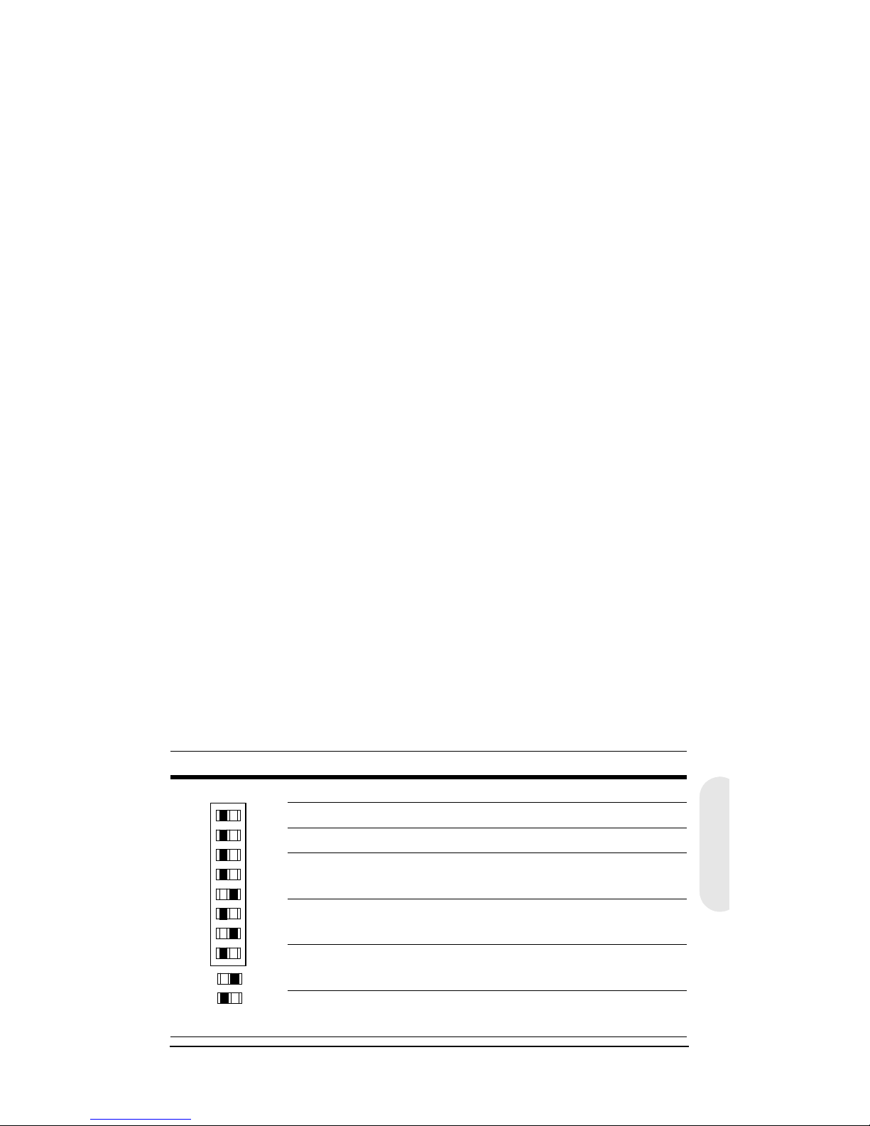
Version 3 6 G-113077-002
02/07
Deutsch
Gegenlichtkompensation (Backlight
Compensation, BLC)
Wenn im überwachten Bereich starker Lichteinfall herrscht
(beispielsweise durch ein Fenster), versucht die Kamera, dies
durch Reduktion der gesamten Belichtung auszugleichen.
Dies führt dazu, dass die Bereiche in der Umgebung des
Fensters zu dunkel werden. Stellen Sie den Schalter BLC auf
ON, um den Silhouetten-Effekt zu eliminieren.
Flimmerfreier Modus (Flickerless Mode, FL)
Stellen Sie den Schalter FL auf ON, um das Bildflimmern
zu unterdrücken. Bei Ausführungen für PAL beträgt die
Belichtungszeit 1/100 Sekunde, bei Ausführungen für NTSC
liegt die Belichtungszeit bei 1/120 Sekunde.
Automatische Verstärkungsregelung
(Auto Gain Control, AGC)
Diese Funktion verbessert die Bildhelligkeit, wenn im
überwachten Bereich nur geringe Helligkeit herrscht. In der
Einstellung OFF beträgt die Verstärkung 11 dB. In der
Einstellung ON beträgt die Verstärkung 30 dB.
Automatischer Weißabgleich (Auto White
Balance, AWB)
Der automatische Weißabgleich sorgt für möglichst
originalgetreue Farbwiedergabe. Stellen Sie die Schalter
WB1, WB2 und WB3 entsprechend der folgenden Tabelle ein.
WB1 WB2 WB3 AWB-Modus
AUS AUS AUS ATW-Modus
AUS EIN AUS AWC-Modus
AUS EIN EIN One-Push-Verriegelung
EIN AUS AUS Festeinstellung Innenbereich
(3200°K)
EIN AUS EIN Festeinstellung Leuchtstoff-
röhrenlicht (4.200°K)
EIN EIN AUS Feste Benutzereinstellung
(4.700°K)
EIN EIN EIN Festeinstellung Außenbereich
(6.300°K)
EE
AES
OFF
OFF
OFF
OFF
OFF
OFF
ME
AI
BLC
FL
AGC
WB3
WB2
WB1
= ON
= OFF
LEGEND
Page 92

Version 3 7 G-113077-002
02/07
Automatische Weißabgleich-Nachführung
(Auto Trace White Balance, ATW)
Dieser Modus deckt einen Bereich von 2.800°K bis 8.000°K
ab und wird typischerweise im Innenbereich verwendet.
Automatischer Weißabgleich mit Voreinstellung
(Auto White Balance Control, AWC)
Dieser Modus deckt einen größeren Bereich von 2.000°K bis
10.000°K ab. Die Reaktionsgeschwindigkeit ist höher als im
Modus ATW. Dieser Modus wird vorzugsweise im
Außenbereich oder in Umgebungen mit schwankenden
Lichtverhältnissen eingesetzt.
One-Push-Verriegelung
Drücken Sie an der Rückseite der Kamera die Taste
PUSH LOCK, um den Weißabgleich für das aktuelle Motiv
auszulösen. Dieser Modus wird vorzugsweise in Bereichen
mit konstanten Lichtverhältnissen eingesetzt.
Auswahl der Synchronisierung (LL/INT)
Mit diesem Schalter wählen Sie den Synchronisationsmodus
der Kamera aus. Wenn die Kamera an eine Wechselstromversorgung angeschlossen ist, wird mit der Funktion
„Line lock (LL)“ (Synchronisierung mit Netzfrequenz) die
Bildfrequenz der Kamera so eingestellt, dass jede Kamera im
System zum selben Zeitpunkt eines Wechselstromzyklus
ausgelöst wird. Die Standardeinstellung ist LL.
Page 93

Version 3 8 G-113077-002
02/07
Deutsch
VORSICHT! Bei Betrieb an 12-V-Gleichspannung
muss der Schalter LL/INT auf INT
gestellt werden.
Trimmpotentiometer für die
Synchronisierung mit der Netzfrequenz
Wenn die Kamera im Modus „Line lock“ läuft, kann der
Punkt eines Wechselstromzyklus ausgewählt werden, an
dem die Kamera ausgelöst wird. Diese Funktion ermöglicht
die Synchronisierung von Kameras, die an verschiedenen
Phasen angeschlossen sind.
Das Trimmpotenziometer V-PHASE ermöglicht es, den
Auslösepunkt um 270 Grad (bezogen auf einen
Netzfrequenzumlauf) zu verstellen. Bei Drehung des
Potenziometers im Uhrzeigersinn erfolgt die Auslösung
früher, bei Drehung gegen den Uhrzeigersinn erfolgt die
Auslösung später. Die werkseitige Voreinstellung liegt am
Nulldurchgang der Phase. Wenn alle Kameras an
derselben Phase liegen, sollte die Synchronisierung nicht
verändert werden.
L/L
INT
V-PH
-+
PUSH
LOCK
IRIS
LEVEL
V-P H
PWR
VIDEO
L/L
INT
VSD
DC
ME
AI
BLC
FL
AGC
WB3
WB2
WB1
EE
AES
OFF
GND
DC 12V
AC 24V
Page 94

Version 3 9 G-113077-002
02/07
Installation des Objektivs
Einstellung des Auflagemaßes
Die Einstellung des Auflagemaßes erfolgt an der
Vorderseite der Kamera. Damit kann die Bildschärfe
korrigiert werden.
Der Einstellbereich ermöglicht die Verwendung von
Objektiven mit C- und CS-Montage ohne Distanzring.
Abbildung 4 C/CS-Montage
1. Lösen Sie die Madenschraube mit einem
Kreuzschlitzschraubendreher.
2. Stellen Sie das Bild mit dem Einstellring scharf.
3. Ziehen Sie die Schraube wieder an.
CCS
Madenschraube
Page 95

Version 3 10 G-113077-002
02/07
Deutsch
Abbildung 5 Pinbelegung für DC- und VSD-
Objektive
1
2
3
4
21
43
Pin Objektiv mit Direktantrieb
(DC)
Objektiv mit Videoantrieb
(VSD)
1 CTRL – Stromversorgung (+12 V)
2 CTRL + nicht belegt
3 DRV + Videosignal
4 DRV – Masse
Stellen Sie den Schalter
auf DC.
Stellen Sie den Schalter
auf VSD.
Anschluss für Objektiv mit automatischer Blende
Page 96

Version 3 11 G-113077-002
02/07
Abschließen der Installation
Montage der Kamera
An der Oberseite der Kamera sind Montagepunkte
vorgesehen, so dass die Kamera an einer Halterung oder
auf einem Stativ befestigt werden kann. Die Bohrungen
sind für handelsübliche Schrauben der Größe 1/4 x 20
vorgesehen. Je nach Anwendung kann diese Halterung
abgeschraubt und an der gegenüberliegenden Seite der
Kamera angebracht werden. Die Montagehalterung muss
das Gewicht der Kamera und des Objektivs tragen können.
Hinweis Einige Sicherheitsvorschriften besagen, dass
die Montagehalterung sogar für das vierfache
Gesamtgewicht von Kamera und Objektiv
ausgelegt sein muss.
Abbildung 6 Montage der Kamera
Lösen Sie die drei
Schrauben der
Halterung, und
bringen Sie die
Halterung an der
anderen Seite der
Kamera an.
Page 97

Version 3 12 G-113077-002
02/07
Deutsch
Anschließen der Kamera
1. Verbinden Sie den Anschluss VIDEO an der Rückseite
der Kamera mit dem Video-Eingangsanschluss des
Monitors.
2. Schließen Sie die Kamera an die jeweils vorgesehene
Stromversorgung an.
HCC334L/LX, HCC484L/LX: 12 VDC oder 24 VAC
HCC335LX, HCC485LX: 230 VAC
3. Verbinden Sie das Netzteil mit dem Stromnetz. Die
Betriebsanzeige-LED (PWR) leuchtet und signalisiert
damit, dass die Kamera Stromversorgung erhält.
Wenn diese LED nicht leuchtet, überprüfen Sie alle
Verbindungen und die Stromversorgung.
Abbildung 7 Anschlüsse an der Kamera
PUSH
LOCK
IR IS
LEVEL V-PH
PWR
VIDEO
L/L
IN T
VSD
DC
ME
AI
BLC
FL
AGC
WB3
WB2
WB1
EE
AES
OFF
GND
DC 12V
AC 24V
Monitor
BetriebsanzeigeLED
Abbildung zeigt Ausführung mit
Kleinspannungsversorgung
(HCC334L/LX, HCC484L/LX)
Page 98

Version 3 13 G-113077-002
02/07
Gewährleistung und
Kundendienst
Gemäß den Bedingungen der Gewährleistungserklärung zu
diesem Gerät übernimmt Honeywell während des
Gewährleistungszeitraums nach eigenem Ermessen den
kostenlosen Austausch oder die kostenlose Reparatur defekter
Geräte, die mit vorausbezahlten Frachtkosten an Honeywell
zurückgesendet werden.
Wenn in Verbindung mit einem Honeywell Gerät ein Problem
auftritt, wenden Sie sich bitte an den Kundenservice
(in Nordamerika: 1.800.796.CCTV) und lassen sich einen
Rücksendecode zuteilen (Return Merchandise Authorization
(RMA)). Informationen zur Gewährleistung in Europa erhalten Sie
bei einem Honeywell Vertriebspartner.
Halten Sie bitte die Modellnummer, die Seriennummer und eine
Beschreibung des Problems bereit.
Rücksendungen, Ersatzlieferungen und Gutschriften müssen
vorher autorisiert werden. Sendungen an Honeywell, die ohne
Rücksendecode (Return Merchandise Authorization)
eintreffen, müssen von Honeywell nicht angenommen werden.
Technische Daten
Hinweis Sofern nichts anderes vermerkt ist, gelten diese
Daten für alle Modelle.
HCC334L HCC334LX
HCC335LX
HCC484L HCC484LX
HCC485LX
Betrieb
Bildsensor: Super-HAD-CCD-Sensor 1/3 Zoll (8,5 mm)
Bildnorm: NTSC PAL NTSC PAL
Bilderfassung:
525 Zeilen,
Zeilensprungfaktor 2:1
625 Zeilen,
Zeilensprungfaktor 2:1
525 Zeilen,
Zeilensprungfaktor 2:1
625 Zeilen,
Zeilensprungfaktor 2:1
Anzahl Pixel
(H x V):
510 x 492 500 x 582 768 x 494 752 x 582
Page 99

Version 3 14 G-113077-002
02/07
Deutsch
Minimale Umgebungshelligkeit:
<0,2 lux bei F = 1,2
(50 IRE, AGC EIN)
<0,4 lux bei F = 1,2
(50 IRE, AGC EIN)
Horizontale
Auflösung:
330 TVL 330 TVL 480 TVL 480 TVL
Videoausgang: 1 Vss an 75 Ohm
Synchronisation: Intern/Netzfrequenz
Signal-Rausch-
Abstand:
> 50 dB
Dynamische
Verstärkungsregelung (Auto Gain
Control, AGC):
Ein (30 dB)/Aus (11 dB)
ALC: EE/VSD/DC
Automatische
elektronische
Blende (Automatic
Electronic Shutter,
AES):
1/60 bis
1/100.000 s
1/50 bis
1/100.000 s
1/60 bis
1/100.000 s
1/50 bis
1/100.000 s
Objektivmontage: C/CS-Montage (einstellbar)
Weißabgleich: ATW, AWC, One-Push-Verriegelung, Innenbereich,
Außenbereich, Leuchtstoffröhrenlicht,
Benutzereinstellung
BLC (Gegenlichtkompensation):
Ein/Aus
Gammakorrektur: 0.45
Elektrische Kenndaten
Eingangsspannung:
HCC334L/LX, HCC484L/LX: 12 VDC/24 VAC
HCC335LX, HCC485LX: 230 VAC
Eingangsspannungsbereich:
HCC334L/LX, HCC484L/LX: 11 bis 16 VDC, 17 bis 28 VAC
HCC335LX, HCC485LX: 230 VAC ±10 %
Leistungsaufnahme:
HCC334L/LX, HCC484L/LX: 3.5 W (max)
HCC335LX, HCC485LX: 4.2 W (max)
Mechanische Daten
Maße: (B x H x T) HCC334L/LX, HCC484L/LX: 68 mm x 56 mm x 120 mm
HCC335LX, HCC485LX: 68 mm x 56 mm x 140 mm
Gewicht: HCC334L/LX, HCC484L/LX: 380 g
HCC335LX, HCC485LX: 410 g
Umgebungsbedingungen
Temperatur: Betrieb: –10 °C bis +50 °C
Lagerung: –20 °C bis +70 °C
Normen
Emissionen: FCC, CE (EN55013)
Störfestigkeit: CE (EN50130-4)
Sicherheit: EU: 73/23/EWG LVD
HCC334L HCC334LX
HCC335LX
HCC484L HCC484LX
HCC485LX
Page 100

© 2007 Honeywell International Inc. Alle Rechte vorbehalten. Kein Teil dieser
Veröffentlichung darf ohne schriftliche Genehmigung durch Honeywell Video
Systems reproduziert werden. Die Informationen in dieser Veröffentlichung wurden
mit größter Sorgfalt zusammengestellt. Honeywell Video Systems kann jedoch
keinerlei Haftung für die Folgen übernehmen, die sich aus der Nutzung dieser
Informationen ergeben könnten. Die in diesem Dokument enthaltenen Informationen
können jederzeit und ohne vorherige Ankündigung geändert werden.
Zur Umsetzung solcher Änderungen können überarbeitete Versionen dieser
Veröffentlichung herausgegeben werden.
www.honeywellvideo.com
+1.800.796.CCTV (nur Nordamerika)
HVSsupport@honeywell.com
Dokument G-113077-002 02/07 Version 3
Honeywell Video Systems
(Hauptniederlassung)
2700 Blankenbaker Pkwy, Suite 150
Louisville, KY 40299, USA
www.honeywellvideo.com
℡ +1.800.796.2288
Honeywell Security Australia Pty Ltd.
Unit 5, Riverside Centre
24–28 River Road West
Parramatta, NSW 2150, Australien
www.ademco.com.au
℡
+61.2.8837.9300
Honeywell Security Asia Pacific
33/F Tower A, City Center, 100 Zun Yi Road
Shanghai 200051, China
www.security.honeywell.com/cn
℡
+86 21.2527.4568
Honeywell Security Asia
Flat A, 16/F, CDW Building
388 Castle Peak Road
Tsuen Wan, N.T., Hongkong
www.security.honeywell.com/hk
℡
+852.2405.2323
Honeywell Security France
Parc Gutenberg, 8, Voie La Cardon
91120, Palaiseau, Frankreich
www.honeywell.com/security/fr
℡
+33.01.64.53.80.40
Honeywell Security Italia SpA
Via Treviso 2 / 4
31020 San Vendemiano
Treviso, Italien
www.honeywell.com/security/it
℡
+39.04.38.36.51
Honeywell Security España
Mijancas 1. 3
a
Planta
P.Ind. Las Mercedes
28022 Madrid, Spanien
www.honeywell.com/security/es
℡
+34.902.667.800
Honeywell Video Systems
Nordeuropa
Netwerk 121
1446 WV Purmerend, Niederlande
www.SecurityHouse.nl
℡
+31.299.410.200
Honeywell Video Systems UK Ltd.
Aston Fields Road, Whitehouse Ind Est
Runcorn, Cheshire, WA7 3DL, GB
www.honeywellvideo.com
℡
+0844 8000 235
Honeywell Security South Africa
Unit 6 Galaxy Park, 17 Galaxy Avenue
Linbro Park, P.O. Box 59904
2100 Kengray, Johannesburg
Südafrika
www.honeywell.co.za
℡
+27.11.574.2500
Honeywell Security Deutschland
Johannes-Mauthe-Straße 14
D-72458 Albstadt, Deutschland
www.honeywell.com/security/de
℡
+49.74 31.8 01.0
Honeywell Security Poland
Chmielewskiego 22a, 70-028
Szczecin, Polen
www.ultrak.pl
℡
+48.91.485.40.60
Honeywell Security Czech Republic
Havránkova 33, Brno
Dolní Heršpice, 619 00
Tschechische Republik
www.olympo.cz
℡
+420.543.558.111
Honeywell Security Slovakia Republic
Vajnorská 142, 83104 Bratislava
Slowakei
www.olympo.sk
℡
+421.2.444.54.660
 Loading...