

Page 1

High Resolution Indoor
CAUTION
THIS SYMBOL INDICATES THAT
DANGEROUS VOLTAGE
CONSTITUTING A RISK OF
ELECTRIC SHOCK IS PRESENT
WITHIN THE UNIT.
CAUTION:TO REDUCE THE RISK OF ELECTRIC
SHOCK, DO NOT REMOVE THE COVER.
NO USER-SERVICEABLE PARTS INSIDE.
REFER SERVICING TO QUALIFIED SERVICE
PERSONNEL.
THIS SYMBOL INDICATES THAT
IMPORTANTOP ERATING AND•
MAINTENANCE INSTRUCTIONS
ACCOMPANYTHIS UNIT.
RISK OF ELECTRIC
SHOCK
DO NOT OPEN
Box Camera
HCC10
HCC10X
HCC210
HCC210X
Quick Installation Guide
FCC Compliance Statement
Information to the user: This equipment has been tested and found to comply
with the limits for a Class A digital device, pur suant to P art 15 of the F CC Rules.
These limits are designed to provide reasonable protection against harmful
interference when the equipment is operated in a commercial environment.
This equipment generates, uses and can radiate radio frequency energy and, if
not installed and used in accordance with the instructions, may cause harmful
interference to radio communications. Operation of this equipment in a
residential area is likely to cause harmful interference in which case the user will
be required to correct the interference at his own expense.
Note Changes or modifications not expressly approved by the party
responsible for compliance could void the user’s authority to operate the
equipment.
Canadian Compliance Statement
This Class A digital apparatus complies with Canadian ICES-003.
Cet appareil numérique de la Classe A est conforme à la norme NMB-003 du
Canada.
Manufacturer's Declaration of Conformance
The manufacturer declares that the equipment supplied with this guide is
compliant with the essential requirements of the EMC Directive 2004/108/EC,
the General Product Safety Directive 2001/95/EC and the RoHS Directive
2011/65/EU, conforming to the requirements of standards EN 55022 for
emissions, EN 50130-4 for immunity, EN 60950-1 for electrical equipment
safety, and EN 50581 for assessment of electrical and electronic products with
respect to the restriction of hazardous substances.
800-15951 - A - 09/2013
Warnings
WARNING
qualified and experienced technicians to conform to all local codes
and to maintain your warranty.
WARNING
operation. Do not connect to higher voltage. Use only with NRTLapproved Class 2 power supplies.
WARNING
expose this camera to rain or moisture.
Installation and servicing should be performed only by
This device is configured for 12 V DC or 24 V AC
To prevent the risk of fire or electric shock hazard, do not
Important Safety Instructions
• Read and keep these instructions.
• Please ensure that your installation area can safely support the weight of the
camera.
• Do not install the camera in extreme temperature conditions. Only use the camera
where temperatures are within the limits shown in the specifications section of the
guide. Be especially careful to provide ventilation when operating under high
temperatures.
• Do not aim the camera at extreme light sources to prevent damage to the CCD.
• This camera is rated for indoor operation. Do not expose this camera to rain or
moisture.
• Do not touch the camera lens, dome, or bezel (front glass plate).
• Do not drop the camera or subject it to physical shock.
• Do not use a strong or abrasive detergent when cleaning the camera.
Package Includes
•Camera (1)
• Manuals (3)
• Warranty (1)
• C/CS Mounting Ring (1)
Key Features
•1/3-inch interline transfer CCD
• High resolution: 600 TVL (HCC10/HCC10X); 650 TVL (HCC210/HCC210X)
• High sensitivity: 0.1 lux minimum illumination (F1.2, 50 IRE, AGC on)
• Configurable day/night settings
• Digital noise reduction
•Backlight compensation
• Auto electronic shutter
• Auto gain control
• Motion detection (4 programmable zones)
•Privacy masking (8 programmable zones)
• On-screen display
•Alarm input/output
• RS-485 port for connecting to a keyboard or DVR
• 12 V DC or 24 V AC
800-15951 - A - 09/2013
Page 2
2 | High Resolution Indoor Box Camera
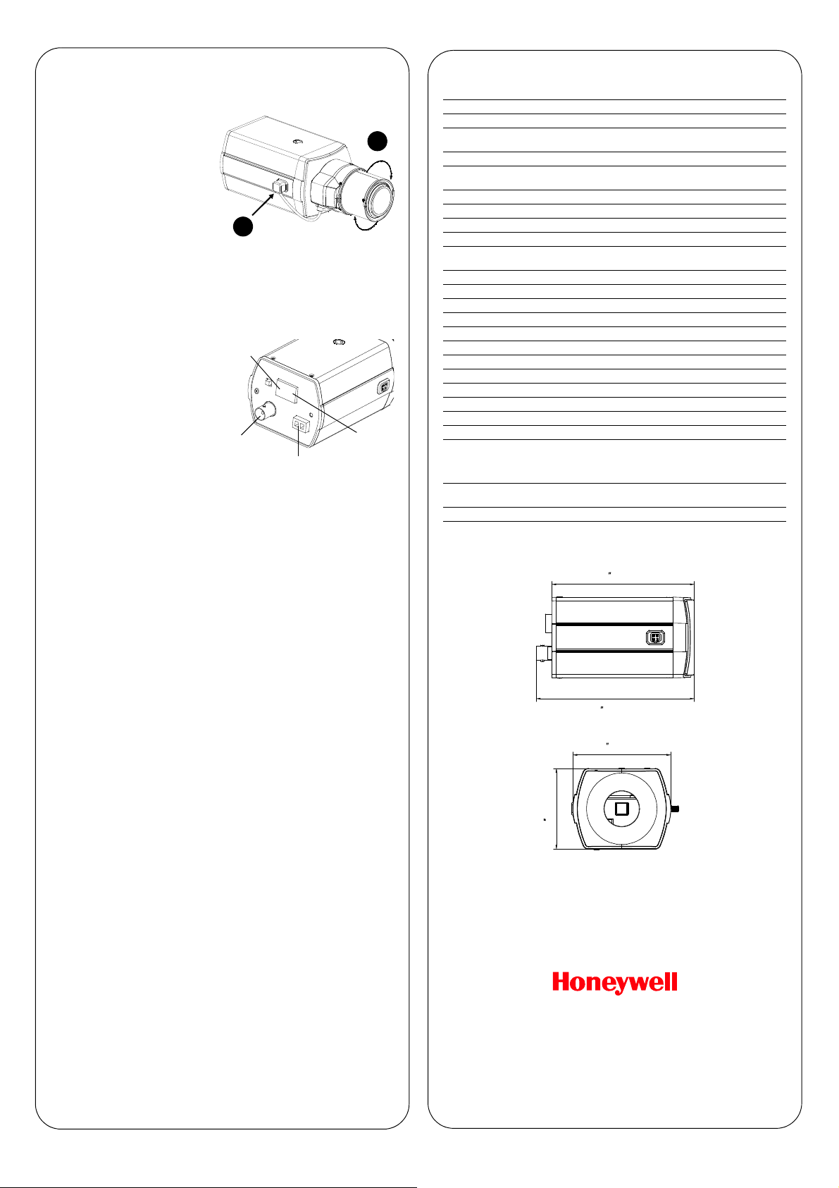
A
B
Power input
(12 V DC or 24 VAC)
Video output
Alarm I/O
D/N input
RS-485
3.9 (100 mm)
4.4
(111 mm)
2.7 (68.8 mm)
2.2 (56 mm)
Installing the Lens
1. Remove the lens mount cap
from the camera (if present).
2. Screw the lens clockwise
onto the lens mount of the
camera (A). If you are using a
C-mount lens, you will need
to attach the C-mount
adapter first.
3. Connect the auto-iris drive
cable to the 4-pin connector
interface on the side of the
camera (B).
Connecting the Wiring
Note Do not turn on the power of any connected equipment until all
connections are completed.
1. Connect the power input of
the camera to an external
12 V DC or 24 V AC power
supply.
2. Connect the video output of
the camera to the video input
of your monitor.
3. Optionally, make alarm input
and output connections.
Alarm input is active when
shorted to ground. Alarm out
is open collector controlled by
alarm in. Absolute maximum
alarm out values are 12 V DC
and 200 mA.
4. Optionally, connect the D/N input of the camera to an external day/night
control and set the OSD Day/Night menu to EXT1 or EXT2. When the
D/N terminal is connected to the ground (G) terminal, the camera is
forced into night mode. The camera remains in night mode until the D/N
terminal is disconnected from the ground (G) terminal.
5. Optionally, connect a DVR or keyboard using the RS-485 terminals
(D+, D–). Connect T+,T– of the DVR or keyboard to D+, D– of the
camera. The default baud rate is 4800, address is 001, and protocol is
Pelco-D.
Note The camera address cannot be changed. Only one camera address is
supported.
Specifications
Video Standard NTSC, PAL
Image Sensor 1/3-inch interline transfer CCD
Number of Pixels (H×V)
Minimum Illumination 0.1 lux color @ F1.2, 50 IRE, AGC on
Horizontal Resolution
Video Output 1.0 Vp-p, 75 ohms
Sync System Internal, line lock
S/N Ratio 50 dB or more (AGC off)
Auto Gain Control 6 dB to 44.8 dB (Manual)
Automatic Electronic Shutter
White Balance ATW/Push/User1/User2/AntiCR/Manual/Push Lock
BLC/HLC Off/BLC/HLC
Day/Night Auto/Day/Night/Ext1/Ext2
Noise Reduction Y reduction
Motion Detection Off/On; 4 programmable zones
Privacy Masking Off/On; 8 programmable zones
Input Voltage 12 V DC/24 V AC (±10%)
Power Consumption 4 W (max)
Dimensions (L×W×H)) 4.4ʺ × 2.7ʺ × 2.2ʺ (111.0 mm × 68.8 mm × 56.0 mm)
Weight 0.88 lb (0.4 kg)
Camera Mount 1/4-20 UNC
Lens Mount C/CS Mount
Connectors
Temperature
Relative Humidity Less than 90%, non-condensing
HCC10(X): 768 × 494 (NTSC); 752 × 582 (PAL)
HCC210(X): 976 × 494 (NTSC); 976 × 582 (PAL)
HCC10(X): 600 TVL
HCC210(X): 650 TVL
1/60–1/100,000 s (NTSC)
1/50–1/100,000 s (PAL)
Lens: 4-pin connector
Video Output: BNC connector
Power Input: 2-pin terminal block
Alarm/DN/RS-485: 6-pin terminal block
Operating: 14°F to 122°F (–10°C to 50°C)
Storage: –4°F to 140°F (–20°C to 60°C)
Mounting the Camera
The camera can be installed to a tripod, housing, wall mount, or ceiling mount
using the 1/4–20 UNC mounting holes on the top and bottom of the camera.
Adjusting the Lens
After installing the lens and connecting the wiring, you can adjust the lens focus
and zoom. If the correct focus cannot be obtained, you can adjust the back
focus manually using the back focus screw on the side of the camera.
To adjust the back focus:
1. Fully open the iris, set the zoom ring (if applicable) to full WIDE, set the
focus ring to NEAR.
2. Loosen the back focus screw, adjust the back focus ring to focus the
picture, and then retighten the back focus screw.
Configuring the Camera
After you have installed the lens, connected the wiring, mounted the camera,
and adjusted the lens focus and zoom, you can configure the camera settings
using the on-screen display (OSD) setup menu.
For more information about setting up the camera, refer to the High Resolution
Indoor Box Camera User Guide (800-15952).
www.honeywell.com/security
https://www.honeywellsystems.com/ss/techsupp/index.html
© 2013 Honeywell International Inc. All rights reserved. No part of this publication m ay be reproduced by any
means without written permissio n from Honeywell. The information in this publicatio n is believed to be accurate
in all respects. However, Honeywell c annot assume responsibility for any consequences resulting from the use
thereof. The information contain ed herein is subject to change without notice. Revisions or new editions to this
publication may be issued to incorporate such changes.
+1.800.323.4576 (North America only)
Document 800-15951 – Rev A – 09/2013
 Loading...