

Honeywell Fire Sentry SS4-AUV, Fire Sentry SS4-AUV2 Installation Manual And Operating Manual
Page 1
Model SS4-AUV/-AUV2 Ultraviolet (UV) Digital E lec tr o-Optical Fire Detector
Installation Guide and Operating Manual
MAN0927_V3_1510-005_Rev H_06-13
i
Installation Guide and Operating Manual
Fire Sentry Model SS4-AUV/-AUV2
Ultraviolet (UV) Digital Electro-Optical Fire Detectors
STAND-ALONE RELAY MODE or 4-20 mA Output Option
Page 2

Model SS4-AUV/-AUV2 Ultraviolet (UV) Digital E lec tr o-Optical Fire Detector
Installation Guide and Operating Manual
MAN0927_V3_1510-005_Rev H_06-13
ii
TABLE OF CONTENTS
PAGE
APPROVALS ................................................................................................................................................................... 1
SECTION 1 TECHNICAL DESCRIPTION.......................................................................................................................... 1
1.1 Features and Specifications ................................................................................................................................ 1
1.1.1 General D escription ....................................................................................................................................... 1
1.1.2 Applications ................................................................................................................................................... 2
1.1.3 Detector Locations ......................................................................................................................................... 3
1.2 Stand-Alone Operation ........................................................................................................................................ 3
1.3 FS2000 System Operation ................................................................................................................................... 3
1.4 Overview .............................................................................................................................................................. 4
1.4.1 Model SS4-AUV/-AUV2 Detector .................................................................................................................... 4
1.4.2 Detection Range and Field-of View ................................................................................................................. 4
1.5 Configuration Settings ........................................................................................................................................ 4
1.6 Testing ................................................................................................................................................................. 5
1.6.1 Special Conditions for Testing ........................................................................................................................ 5
1.6.2 Automatic Testing .......................................................................................................................................... 5
1.6.3 Manual Testing .............................................................................................................................................. 5
SECTION 2 INSTALLATION............................................................................................................................................. 6
2.1 Installation Instructions ....................................................................................................................................... 6
2.1.1 Installation Precautions .................................................................................................................................. 6
2.1.2 Conduit Installation......................................................................................................................................... 6
2.1.3 Wiring Recommendat ions............................................................................................................................... 6
2.1.4 Power Supply Considerations ......................................................................................................................... 6
2.2 Installation Procedure ......................................................................................................................................... 6
2.2.1 Configuring and Wiring Detectors ................................................................................................................... 6
2.2.2 Removing Detector from its Enclosure. .......................................................................................................... 7
2.2.3 Configuring the Det ector Module.................................................................................................................... 7
2.2.4 Wiring the Detector Module. ............................................................................................................................ 7
2.2.5 Wiring the SS4-AUV/-AUV2 Detector for 4 or 20 mA Current Mode Operation (Optional) .................................. 8
2.2.6 Wiring the Detect or Relays ............................................................................................................................. 9
2.2.7 Replacing the Detector Module in the Enclosure. ............................................................................................ 9
2.3 Enclosure Installation (optional) ......................................................................................................................... 9
SECTION 3 TROUBLESHOOTING AND MAINTENANCE .............................................................................................. 12
3.1 Model SS4-AUV/-AUV2 Detector Faults............................................................................................................. 12
3.2 Cleaning Windowed Enclosures and Detectors ................................................................................................ 12
3.3 Personnel Training ............................................................................................................................................ 12
3.4 Detector Repair .................................................................................................................................................. 13
DETECTOR PINOUT DATA ........................................................................................................................................... 14
Verification Time...................................................................................................................................................... 15
Latching .................................................................................................................................................................. 15
Test Cycle ............................................................................................................................................................... 15
Fire Range .............................................................................................................................................................. 15
SECTION 4 OPTIONAL ACCESSORIES ....................................................................................................................... 16
4.1 Air Shield for Applications in Contami nated Environment (Part No. DASA1-P) ............................................... 16
4.2 PC Software Kit (2029-INTERFACE-KIT) ........................................................................................................... 16
4.3 4-20 mA Option (MA420-4) ................................................................................................................................. 16
4.4 Detector Mounts (SM2 or SM4) .......................................................................................................................... 16
4.5 Test Lamp (Part No. FT2045) ............................................................................................................................. 16
INDEX ............................................................................................................................................................................ 17
Page 3

Model SS4-AUV/-AUV2 Ultraviolet (UV) Digital E lec tr o-Optical Fire Detector
Installation Guide and Operating Manual
MAN0927_V3_1510-005_Rev H_06-13
1
APPROVALS
The Model SS4-AUV/-AUV2 Ultraviolet Fire Detectors have been manufactured in compliance with the
requirements of the ISO-9002 standard and have been approved by:
• F ac tory Mutual (FM) for the United States
• CSA for Canada
SECTION 1
TECHNICAL DESCRIPTION
1.1 Features and Specifications
1.1.1 General Descriptio n
The Model SS4-AUV/-AUV2 Ultraviolet Fire/Flame Detectors are fast-r eacting (within 5 seconds), digi tal,
configurable, computerized, “sm ar t” units. They are capable of solar-blind flame detecti on in the ultra-violet
spectral range (185 to 260 nanometers) utilizing long-life twin ruggederized UV sensors. They are
equipped with SRL-BIT (Built In Test) for optical “through the lens” of both the sensors and lens. The
Model SS4-AUV/-AUV2 Ultraviolet Fire Detect or has sensitivity to Type A, B, and C flaming fires, false
alarm immunity, and an alarm range between 15 and 60 ft. to a one square foot gasoline pan fi re, with a
120-degree (± 60 degrees from the axis) conical field of view. Their microprocessor-based algorithms
(FirePic, SnapS hot, and Tri-Mode Plot) assure tim e programmable alarm verification, Fi re Signature
Analysis, and compatibility with standard approved fire alarm panels.
The Detector also has the flexibilit y to be re-configured i n the f iel d. It s i nstall ation i s sim ple, and operati on
straightforward due to the built-in self-testing feature. Therefore, the maintenance consists mainly in
keeping the Detec tor window lens clean, and performing periodi c testing requi red by the manufacturer of
the Fire Control and Suppression System . The SS4-AUV/ SS4-AUV2 are UV only det ectors and are f or
indoor applications where UV noise sources, such as weldi ng, are not present.
1.1.2 Detector Technical Specifications
1.1.2.1 Mechanical Specif ications
Enclosure Material: Copper Free Aluminum
316 Stainless Steel
Physical Dimensi ons: Assembly 4.35 in. (
110.49 mm) Height X 4.81 in. (122.24 mm) Diameter
Mounting Holes ¼ in. (
6.35 mm) Diameter, 5.50 in. (139.70 mm) Center to
Center
Conduit Entri es Two (2) ¾ in. NPT or Two (2) 25 mm
Weight: Aluminum 3 lbs. 11 oz. (
1.7 kg) approx imately
Stainless Steel 7 lbs. 7 oz. (
3.4 kg) approx imately
Enclosure Rati ng: IP66 / NEMA 4X
Vibration: Meets or exceeds Mil Spec 810C,
Method 514. 2, Curve AW
1.1.2.2 Electrical Specifications
Input Voltage Range: 18 VDC to 32 VDC
Normal Operation Cur r ent: 60 mA (
nominal) 205 mA (nominal with heaterP
1
P
)
Maximum Fire Alarm Curr ent: 85 mA (
maximum) 235 mA (maximum wit h h eaterP
1
P
)
Relay Contact Rating: 1 Amp @ 24 VDC resistiv e
Analog Current Output: 0 to 20 mA (
Source or Sink, User Selectable)
(
400 Ohms M ax L oad) 0.0 mA (<0.6 mA) = Fault
2.0 mA (
±0.6 mA) = Dirty Window Lens
4.0 mA (
±0.6 mA) = Normal, Saf e ( no Fault, no Fire)
20.0 mA (
±0.6 mA) = Verified Fire Alarm
Screw Terminal Wire Sizes: 12 AWG to 22 AWG (2.50 mm to 0.7 6 2 mm)
Use str anded c onduc tors (
UnotU solid core)
Page 4

Model SS4-AUV/-AUV2 Ultraviolet (UV) Digital E lec tr o-Optical Fire Detector
Installation Guide and Operating Manual
MAN0927_V3_1510-005_Rev H_06-13
2
1.1.2.3 Environmental Specifications
Operating Temperature Standard: -40° F to +185° F (-40° C to +85° C)
Operating Humi dity Range: 5 to 98% RH non-condensing
Storage Temperature: -67° F to +221° F (-55° C to +105° C)
1.1.2.4 Performance Sp ecifications
P
2
P
Field of Vi ew: 120° Horizontal and Vertical (conical)
Sensitivity One (1) sq. ft. heptane reference fir e at 60 feet
Speed of Response: 2 to 5 seconds (typical)
High Speed Response: Less than 0.5 seconds to “fireball” type fires
(if selected)
Spectral Sensitivity 0.4 to 3.5 micron wavelengths, TriBand Dual IR Plus
1.1.2.5 Hazardous Area Classif ications
North America, ATEX, IECEx:
Class
I, Divisi on 1, Groups A, B, C & D Class I, Zone 1,
Class
II, Divi si on 1 Groups E, F & G AEx d IIC xx, II 2 G Ex d IIC xx
Class
III II 2 D Ex tD A21 IP66 T135°C
T4: Ta = -40°C to +110°C3 xx= T4: Ta = -40°C to +110°C3
T5: Ta = -40°C to +75°C
3
T5: Ta = -40°C to +75°C3
T6: Ta = -40°C to +60°C T6: Ta = -40°C to +60°C
InMetro:
Ex d IIC xx Gb
xx= T4: Ta = -60°C to +110°C3
T5: Ta = -60°C to +90°C
3
T6: Ta = -60°C to +75°C
1.1.2.6 Additional Certifications
FM verified and approv ed to meet FM 3260 Radiated Energy-Sensing Fire Detectors for Automatic
Fire Alarming Signals.
1
P
Heater circuit turns ON only when temperature drops below zero degrees Fahrenheit (-17° C)P
2
Se e Sectio n 1.4 for Additional Performance Specifications
3
The supply connection wiring shall be rated at least 10°C above the rated service temperature (120°C for T4 applications and 85°C
for T5 applications)
1.1.2.7 Other Specifications:
LED Vis ua l Indicators:
Powered Detector: Dual LEDs blink every 10 seconds
Fault Declar ed: One LED turns ON solid until the fault is cured
Re-calibrate when: Both LEDs flash ON and OFF rapidly
Fire Declared: Both LEDs ON solid (one LED blinks during first few seconds)
Relay Contact:
Rating: 0.5 Amp at 120 Volt AC or 1 A at 24 V DC resistive
Fire relay: N.O. and N.C. contacts (Latching/ Non-Latching, switch selected)
Verification relay: N.O. and N.C. contacts (Adjustable time from 0 to 30 seconds)
Fault relay: N.O. and N.C. contacts
1.1.3 Applications
Applications of the Model SS4-AUV/-AUV2 Detector s include warehou ses, ai rc raft hangars, pet rochemi cal
facilities, Gas turbines, and Power plants, among others.
Page 5

Model SS4-AUV/-AUV2 Ultraviolet (UV) Digital E lec tr o-Optical Fire Detector
Installation Guide and Operating Manual
MAN0927_V3_1510-005_Rev H_06-13
3
1.1.4 Detector Location s
For unobstructed perf ormance, considering Det ector locations in application ar eas, avoid sources, other
than fire, which may cause fal se alarm s, such as oper ati ons uti li zing weldi ng or gas torch eq ui pm ent, hi gh
power sources of EMI or RFI , or artifici al lighting poi nted directly at the Detector . Locations experi encing
strong mechani cal or acoustical vibrations should al so be avoided. For optimum performance, l ocate the
Detector(s) as close as possi ble to the potenti al fire source, preferabl y, along the axis of the vision cone.
Install enough Detectors to completely eclipse the fire hazardous area. Assure accessibility for the
Detector lens cleaning, as well as best possible protection and/or cleaning from fog, rain, ice, dust,
hazardous atmospheres, an d other adv erse elem ents. If necessary, uti lize t he Steel Swivel Mount (Model
SM2) or 316 Stai nless Steel Swivel Mount (Model SM4) for gr eater flexibility in m ounting locations (See
Figures 4 and 5).
1.2 Stand-Alone Operation
For Stand-Alone operation, the Model SS4-A/-A2 Detector may be connected to a suitably approved
transmitt er or control system/panel . T he Detector operat ed in the Stand-Alone mode, uses the Fire, Fault ,
and Verify ( optional) relays or opti onal 4 to 20 mA c urrent source (FSC Model M A420-4 Module, ref er to
Section 4. 3) to interface to F M A ppr ov ed or UL listed Fire /S ec uri ty Panels. For Stand-A lone operation, the
Detector's Fault relay is automatically configured by its on-board microprocessor. The input c ur r ent of the
Model SS4-AUV/-AUV2 Detector is about 15 m A higher in the Stand-Alone mode c om pared to FS2000
System operati on.
NOTE: The Fault relay is not available when the Detector is wired to the FS2000 System.
1.3 FS2000 System Operation
For FS2000 System operat ion, the Model SS4-AUV/-AUV2 Fire and Fault signal s are sent digitally to the
FS2000 System Contr oller using the four wire FS2000 FireBus. The Fi reBus pr ovides 24 Volt DC power
for the Detector and RS-485 digital communication (Refer to Fire Sentry document MN0003: "FS2000
FIRE EARLY WARNING SYSTEM - INSTALLATION and OPERATIONS G UIDE"). For special rem ot e
alarm applic ations, users may also connect directly to the Detec tor’s Fire alarm relay.
NOTE: When the Model SS4-AUV/-AUV2 Detector is connected t o the FS2000 System using FireBus
communicati on, t he Controller automatically disables the Detector’s Fault relay.
Page 6
Model SS4-AUV/-AUV2 Ultraviolet (UV) Digital E lec tr o-Optical Fire Detector
Installation Guide and Operating Manual
MAN0927_V3_1510-005_Rev H_06-13
4
1.4 Overview
1.4.1 Model SS4-AUV/-AUV2 Detector
Version SS 4-AUV: There are two (2) LED s o n the Mo del SS4-A UV Detec tor t hat i ndicat e the stat e of the
Detector. During normal operati on both LEDs will blink every 10 seconds.
If the Detector alarms to a fire, it energizes the Fire relay and turns on both LEDs in the following
sequence. One LED i s turned on immediately and the second LED wil l rapidly blink f or several seconds
indicating that the Detector's FirePic spectra is being permanently stored in the Detector's solid-state
memory (FirePi c is the several seconds of Det ector spectral data which precedes an alarm event). Once
the FirePi c data is stored, the second LED will remain on. For this version, the fire alarm LEDs turn on and
remain on until power to t he unit is cycled (turned off and on again).
If the Detector has a Fault, it de-energizes the Fault r elay and tur ns one (1) LE D on ( the LED will not light if
the Fault is a “No Power Faul t”). If the Fault condition, such as a “Low Volt age Fault”, is eliminated the
Detector will autom atically return to Normal Operation.
NOTE: Faults caused by excessive i nput voltage or due to temperatur es outsi de the operating temper ature
range require factory re-certifi c ation. Re-certification is required if a Fault is indic ated by both LEDs rapidl y
blinking (with frequency about 2 Hz.).
Version SS4-AUV2: The operation of this unit is identical to the S S 4-A UV, ex c ept the fire alarm LEDs tur n
off once the fire threat is eliminated, without power cycling of t he device.
1.4.2 Detection Rang e and Field-of View
The SS4-AUV/-AUV2 det ection range is f ield adjustabl e between 15 and 60 f t. in 15 f t. increment s to an
industry standard one square foot gasoline pan fire within 5 seconds.
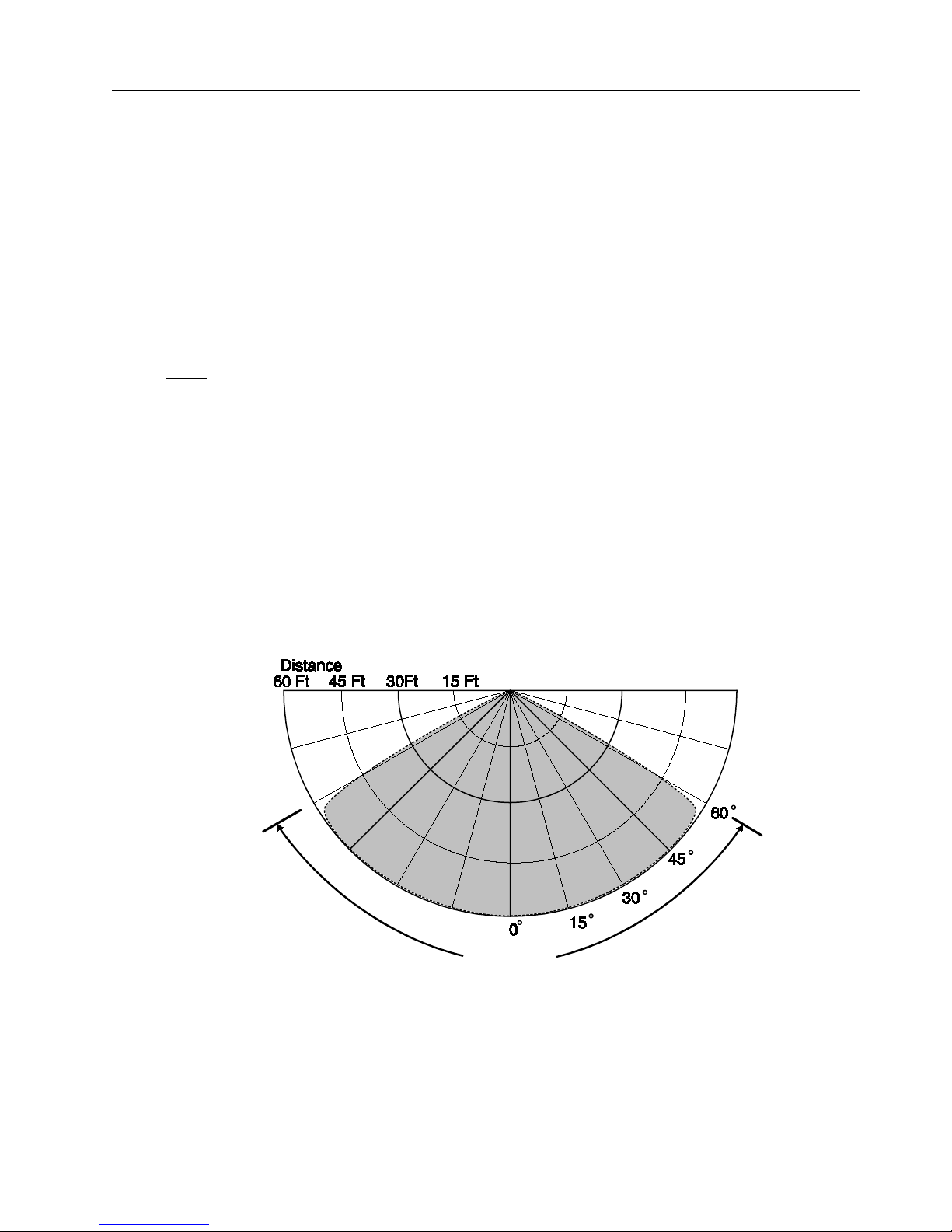
The Detector incorporates a 120-degree conical F ield of View. The fire emissions received by the Det ec tor
diminish at ex treme range and edge s of the fi eld-of-view. It is recommended t hat the Det ector be point ed
at the fire thr eat area for the f astest response tim es to the sm allest size fi re. When multipl e Detectors are
used to cover large areas, the F i eld-of-Views should ov erlap to insure com pl et e coverage of the fire t hreat
area. The Fi eld-of-View is not, howev er, lim ited t o 120 degree s. Larger f i res outsi de the 120 degre e Fi el dof-View may c ause the SS4-AUV/-AUV2 to al arm. T his is based on t he Inv ersed Square L a w for r adiat ed
energy, a larger size fi re outside t he Detecti on Range and fi eld-of-view may cause the Detec tor to al arm.
Refer to Figure 1.
120 Degrees
Figure 1: Field of View, Horizontal, and Vertical.
Sensitivity to 1 Sq. Ft. Gasoline Pan Fire
1.5 Configuration Settings
The SS4-AUV/-AUV2 Detector may be reconfigured in the fiel d and thus optimized for speci al applications.
The configuration of the Detector is set using DIP switches located on the middle circuit board of the
Detector Module. The DI P switch sett ings for each configuration are listed in Table 2.
These configurable options include:
Page 7

Model SS4-AUV/-AUV2 Ultraviolet (UV) Digital E lec tr o-Optical Fire Detector
Installation Guide and Operating Manual
MAN0927_V3_1510-005_Rev H_06-13
5
1. F ire Verify Relay - The V er ify Relay m ay be disabled or enabled with several Verify Time settings. It also
may be set as another Fire Relay. The Verify Time may be set from 5 to 30 seconds in 5 seconds
increments. The Factory setting: Veri f y Relay Di sabled.
When the Verify Relay is enabl ed and Verif y Time is set the V erify Relay will ener giz e and the Fi re Relay
will de-energize if the fire condi tions are sti ll pr esent at t he end of the Verify Time period. In t he opposit e
case, the Detector will wait for 5 seconds plus another Verify Time period t o test for the fire conditions.
This wait and verif y cycl e will r epeat 10 times or until the presence of the fire is confirmed. If the presence
of the fi re is not established the Fir e Relay will remain energi zed unless Non-Latching m ode is set. In
case a subsequent fir e is detected the entire verifi cation process will be r epeated. The state of the Fire
and Verify Relay after the verification process will depend on the choice between Latching and NonLatching modes.
NOTE: When the Verify Relay is enabled and Verify Time is set, the Fire Relay w il l de-energize
when the Verify Relay is energ ized.
2. Latching / Non-Latching - The Fi re Relay and Verify Relay m ay be set in a Latching or Non-Latching
mode. The Factory sett in g for the SS4-AUV is Latching and the SS4-AUV2 is Non -Latching.
If the SS4-AUV or SS4-AUV2 Latching mode is sel ected, the F i re or Ver ify Rel ay will energi ze and Red
LEDs will remain illuminated until the Detector power is cycled ( power i s tur ned off then on).
If the SS4-AUV Non-Latching mode is selected, the Fire or Verify Relay will de-energize after 10
seconds and the Red LEDs will remain illuminated until power is cycled.
If the SS4-AUV2 Non-Latching mode is selected, t he Fire or Verify Relay will de-energi ze and the Red
LEDs will turn-off after 10 seconds.
3. T est Period - This setti ng pertains to the T hrough-the-Lens t est period, whic h may be set to 6 or to 30
minutes. The Facto ry set ting is 30 minutes. The 6-minute period may be requir ed in applications where
the lens is frequentl y obscured.
NOTE: Utilization of the 6-minute period may adversely affect the source tube service life.
4. F ire Detection Range S et t in g - 15, 30, 45, or 60 ft. The Factory setting i s 45 f t .. This setting should be
changed only if the Det ector is locat ed too cl ose to t he fi re t hreat ar ea and in the presence of abnorm all y
high UV.
1.6 Testing
1.6.1 Special Cond itions for Testing
The SS4 Detect or shoul d be tested immediately af ter installation, after r epair or maintenance involving wiring
or model replacement, aft er peri odic maintenance, or after lens contamination has been identified.
1.6.2 Automatic Testing
Automatic SLR-BIT (Built In Test) “ through-the-lens” self -testing i s performed, during Det ector operati on, for
virtually all-i nternal electr onic system s at the selected Test Per iod (Secti on 1.5, 3). One of the Red LEDs will
remain illumi nated (Fault) to indicate contami nation of the windo w lens, mi ssing the protectiv e Self-test grill,
or when removing the enclosure cover.
1.6.3 Manual Testing
For manual testing, the SS4-AUV/-AUV2 Detector may be exposed to an actual industry standard open
flame or t o a Test Lamp simulati ng a fire in the UV band. I t is mandatory t o use the handheld UV/IR T est
Lamp, Model s FT-2045 or FT-2145 f or Fire Sent ry Corporation SS4 t ype Fire Detectors. T he FT-2045 and
FT-2145 Test Lamps are housed in an Explosion-Proof enclosure, powered by internal rechargeable
batteries, and desi gned for indoor and outdoor use. For addi tional informati on on the Test Lamp, ref er t o
FSC Specification SP0242 for FT-2045 or 1505-008A for FT-2145.
NOTE: Other manufacturers UV/IR Test Lamps should not be uti lized to test FSC UV Detector s; c onversely,
the FT-2045 or FT -2145 Test Lamps should not be utilized for testing other manufacturer’s Detec tors.
Page 8

Model SS4-AUV/-AUV2 Ultraviolet (UV) Digital E lec tr o-Optical Fire Detector
Installation Guide and Operating Manual
MAN0927_V3_1510-005_Rev H_06-13
6
SECTION 2
INSTALLATION
2.1 Installation Instructions
This section descri bes the installation of the Model SS4-AUV/-AUV2 Detector for the Stand-Al one relay
mode. It i s recommended that j unction box es be us ed to wire t he Detectors. Det ermi ne the confi guration
settings for the device(s) and the number of connections to be used (Fir e, Fire Verify , Fault, and Power)
depending on desired Det ection Range and Fi re Control Panel type used (refer to the Fir e Control Panel
Manual).
2.1.1 Installation Precau t io ns
The following prec autions should be observed during installation of Model SS4-AUV/-AUV2 Detectors.
1. Mak e sure t hat the external electrical power is tur ned
OFF before c onnec ting the Detector.
2. Printed circuit board components of the Detector are susceptible to damage from electrostatic
discharge. Do not handle the Detector's module (and its printed circuit boards) without
adequate groundi ng and observing all nec essary measures to prev ent the effect of el ectrostatic
discharge (ESD).
2.1.2 Conduit Installation
When planning the conduit , f ollow these recommendations.
1. If only one of the two 3/4 inch NPT conduit openings on the Model SS4-AUV/-AUV2 Detector
enclosure is used, seal the unused opening with a threaded plug and approved sealing material.
2. I n ar eas where moisture may accumulate, install an approved conduit trap or drain.
3. A seal shall be install ed 6” f rom the enclosure wall for al l applic ations requiri ng a Class I , Div. 1
Explosion-Proof rating.
2.1.3 Wiring Recommendations
To prevent i ntermittent connecti ons, Fire Sentry Corporat ion recommends using junc tion boxes. Install a
junction box near each Detector location. Wire each Detector to its junction box. Use screw-down
terminal stri ps i nsi de the junction box to make the connections from t he Detector's terminals to an FM
Approved or UL listed Fi r e Al arm Panel. Also use FM/UL Approved junction boxes and terminal strips.
NOTE: Avoid wire splices. How ever, if wire splices are necessary, al l splices sho uld be soldered.
Utilization of good wiring practices will simplify installation, improve reliability, and facilitat e m aintenance.
2.1.4 Power Supply Considerations
The Model SS4-AUV/-AUV2 Detector uses 24 Volts DC at a maximum cur r ent of 50 mA (wit h the 4-20 mA
option the max imum supply current is 70 m A). Make sure that the Panel's po wer supply can handle th e
load current of the total number of Detectors connect ed to it. F or example, if 10 (ten) SS4-AUV/-AUV2
Detectors are used on a singl e Panel 's power suppl y (multi ply 50 mA 10 times); the power suppl y must be
able to handle at least 500 mA + 10% (0. 50 A + 10%). This load current must also be c onsidered whe n
calculating the Panel's requirements for 24-hour power backup.
2.2 Installation Procedure
2.2.1 Configuring and Wiring Detectors
To configure and wire a Model SS4-AUV/-AUV2 Detector, or to replac e the Detector module, the modul e
must be remov ed from the encl osure. After the configuration sett ings and wiri ng connecti ons hav e been
completed, the module should soon be re-installed in the enclosure to avoid contamination from the
environment.
NOTE: Avoid touching the Detector sensors at the front of the Detector modules. If touched
accidentally, they should be cleaned per instructi ons of Sect ion 3.2.
Page 9

Model SS4-AUV/-AUV2 Ultraviolet (UV) Digital E lec tr o-Optical Fire Detector
Installation Guide and Operating Manual
MAN0927_V3_1510-005_Rev H_06-13
7
2.2.2 Removing Det ector f rom its Enclosure.
a. With el ectrical power off (verify that el ectrical power is of f by making sure that the Detector' s
LEDs do not bli nk for at least 15 seconds), loosen th e Allen-head screw at the ba se of the
metal enclosure top lens cover.
b. Remove the cover and set it aside along with the “O” ring avoiding c ontamination.
c. Remove the three Philips head captive screws located on the top circuit board.
d. Carefully lift out the module, sliding it along the three metal standoffs.
2.2.3 Configurin g the Detect or Module.
Set the DIP switches located on the center PC board of the Detector module to the desired
settings. Refer to section 1.5 and Table 2 for DIP Switch settings
2.2.4 Wiring the Detector Module.
a. Insert the cabl es into t he metal enclosure base throug h one of t he conduit openings. Ref er to
Figure 6
b. Connect the 24 Vol t DC power supply wires to pins 1 (-) and 4 (+) of the J1 or J2 connector
observing the correc t polarity. Refer to Figure 2. Firmly tighten down the two slotted screws
with a small screwdriv er taking care not to over-tighten the screws.
Pins 2 and 3 of the J1 and J2 connectors are the RS-485 interfac e used only for downloading the
FirePic from the Detector’s non-volatile memory, or for viewing the Tri-Mode Plot. It is
recommended t o wire pins 2 and 3 to a separat e junc tion box and proper ly identify them f or futur e
use. A color-coded, multi-connector, shielded, UL-rated cable with 18 to 24-gauge wire is
recommended f or connecting to J1 or J2. The following color-coding i s suggested as a guideline:
Pin 1 Pin 2 Pin 3 Pin 4
Black Green or Blue White or Yellow Red
DC
RETURN ( - ) RS-485( - ) RS-485( + ) +24 VDC POWER ( + )
*Fault Relay
Verify
Relay
*Fault relay i s shown in the energized condition during norm al oper ation (No Fault)
Figure 2: Bottom View of SS4-AUV/-AUV2 Detect or Module
Page 10

Model SS4-AUV/-AUV2 Ultraviolet (UV) Digital E lec tr o-Optical Fire Detector
Installation Guide and Operating Manual
MAN0927_V3_1510-005_Rev H_06-13
8
2.2.5 Wiring the SS4-AUV/-AUV2 Det ect or for 4 or 20 mA Current Mode Operation (Optional)
For applicati ons requiring a 4-20 mA analog output, order t he Detector wit h the Optional 4-20 m A
Module Assembl y, P/N MA420-4. T he module must
be Fact ory installed and cert ified along wit h
the Detector.
The following analog output levels are available from the Detector equipped with the MA420-4
Module. The module is capable of driving a maximum load impedance of 283 Ohms:
NORMAL Operation 4 +/- 0.6 mA
ALARM 20 +/- 0.6 mA
FAULT < 0.6 mA
To use the analog output of an SS4-AUV/-AUV2, make the following connections:
24 V DC J2, pin-4
24 V DC RTN J2, p in-1
4-20 mA output J5, pin-4 (+)
4-20 mA RTN J1, pin-1 (-)
The fire Al arm and fault rel ays of the Detect or equi pped with t he MA420-4 Modul e are not u sabl e.
However the Detect or’s Verify Relay may still be used as a separate Fire Alarm output. Refer to
Table 2: “Configuration DIP Switch Settings” to set DIP switches properly.
NOTE: J1 is a "loop through" connec tion to J2. The +24 V supply is connected to J2 pin 4. The
red lead connection of the MA420-4 must stay in J1, pin-4. Also, the 8.66 K Ohm
supervising resi stor must
remain connect ed at the Fir e Alarm rel ay contact s J4 pin-4 t o J4
pin-1, or a Fault condition will occur.
Figure 3: SS4 Detector Modul e with MA420-4 Inst all ed
(Rear View)
Page 11

Model SS4-AUV/-AUV2 Ultraviolet (UV) Digital E lec tr o-Optical Fire Detector
Installation Guide and Operating Manual
MAN0927_V3_1510-005_Rev H_06-13
9
2.2.6 Wiring the Detector Relays
a. Insert relay cables into the Detector enclosure base through one of the conduit openings.
Refer to Figure 6.
b. Fire Alarm Relay - Connect wires for Fire Alarm to the appropriate J4 terminals of the
Detector. F or Normally Open relay contacts, i nstall wires i nto pins 3 and 4 and f irmly t ighten
down the slott ed screws with a sm all screwdriv er. T he Fir e Alarm r elay i s de-energized during
normal operation and will energize when detecting a fire.
c. F ault Relay – Connect wires for Fault to the appropriate t erminals of the J5 connector. For
Normally Closed relay contacts, i nstall wires into pins 3 and 4 and fi rmly tighten down the
slotted screws with a small screwdriv er. The fault relay is energized during norm al operation
and with no f ault det ected, as sho wn in Fi gure 2. The fault relay will de-energize when a faul t
is detected.
2.2.7 Replacing the Detect or Module in the Enclosure.
a. Carefully re-i nstall t he modul e over t he thr ee m etal standof f s and screw it down wit h the t hree
captive screws to the standoffs.
b. If necessary, clean the Detector’ sensors and windowed cover per instructions of Section 3.2.
c. Securely screw down the metal enclosure top windowed cover and tighten the Allen-head
"tamper-proof" screw.
2.3 Enclosure Installation (optional)
2.3.1 Installing the Detector on the Swivel Mount (SM2) or SS Extra Duty (SM4) Swivel Mount
a. Select fastener s for the swiv el mounting such that they will secure it to t he type of material at
the enclosure loc ation.
b. Mount the swivel-mount to the wall assuring correct orientation.
c. Instal l the mounting br acket onto the Detector enclosure using the #¼-20 or #6 mm screws
and nuts provided. If oriented correctly, the outside contours of the mounting ears on the
Detector encl osure and the end s of t he brack et will match. The lar ge diam eter of the threaded
insert should face the enclosure.
d. Screw the enclosure/ bracket a ssembly onto t he ball or s wiv el stud. Tur n the Det ector until the
stud bottoms agai nst the enclosure. Do no t tight en. While holding t he enclosure, tighten the
jam nut against the br acket.
e. While holding the enclosure, loosen the socket head sc r ew on the SM2 swiv el-mount or swivel
release bolt. Position the enclosure in such a way that the conduit openings are located
horizontall y at the bott om on t he SM4. Poi nt t he encl osure in the desired di rec ti on and ti ght en
the appropriat e har dware.
Page 12

Model SS4-AUV/-AUV2 Ultraviolet (UV) Digital E lec tr o-Optical Fire Detector
Installation Guide and Operating Manual
MAN0927_V3_1510-005_Rev H_06-13
10
4.86
4.26
2.95
2.00
0.295
Dia.
4.7”
approx.
Figure 4: Model SM2 Swivel Mount
Figure 5: Model SM4 Stainless Steel Swivel Mount
Page 13

Model SS4-AUV/-AUV2 Ultraviolet (UV) Digital E lec tr o-Optical Fire Detector
Installation Guide and Operating Manual
MAN0927_V3_1510-005_Rev H_06-13
11
2.09
4.66
1.10
0.67
4.38
2.40
3/4
NPT
1.50
Figure 6: Model SS4-AUV/-AUV2 Detector Enclosur e - Side View
Figure 7: Model SS4-AUV/-AUV2 Detector Enclosure - Rear View
Page 14

Model SS4-AUV/-AUV2 Ultraviolet (UV) Digital E lec tr o-Optical Fire Detector
Installation Guide and Operating Manual
MAN0927_V3_1510-005_Rev H_06-13
12
SECTION 3
TROUBLESHOOTING AND MAINTENANCE
3.1 Model SS4-AUV/-AUV2 Detector Faults
The Model SS4-AUV/-AUV2 Detector issues a Fault (or Trouble) condition by de-energizing the Fault
Relay (J5 connector) . The following are Model Detector Fault s:
a. Temperature F ault: The Detector fault s if the internal temperat ure during oper ation rises above 85° C
or fall s below -40° C causing both LEDs to blink r apidly. Corrective action f or this type of fault requires
factory re-certification.
b. Excessive Input Voltage Fault: The Det ector faults if the input v oltage is too high (greater than 45
Volts) causing bot h LEDs to blink rapidly . Corrective action for t hi s type of fault requires f actory recertification.
c. Low Input Voltage Fault: The Detector faults if the i nput voltage is too low. The user should check the
voltage between Pi ns 1 and 4 of the power connector J1 or J2. In this case one LED is on until the
fault is correc ted. If the volt age is below 15 Volts the user should check the wiri ng and the power
supply.
d. No Power Fault: The Detector faults if the input voltage is interrupted or turned off causing the
absence of LED i ndicati on. The user shoul d measure t he voltage bet ween Pins 1 and 4 of t he power
connector J1 or J2. If none or v er y l ow v oltage i s measured, the u ser should check t he wiri ng and t he
power supply.
e. Detector Fault: The Detector fault s if its Optical Sensors f ail the automati c built-i n “through the lens”
test. In this case one LED is on until t he fault is corrected. The user should fi rst clean both inside and
outside of the lens thoroughly, then clean the exposed surface of the Detector sensors and the
protectiv e grill mount ed on the out side of t he housing cover. If the f ault has not been elimi nated aft er
re-assembly and powering up f or 10 to 15 minutes, f ac tory service may be necessary.
f. Relay Fault: The Detector f aults if one of its Relay circui ts fails. In t his case one LED is on unt il the
fault is corrected. The user should return the unit to the factory for servic e.
g. Self-Checking Fault: The Detector faults if its internal microprocessor finds a failure during self-
checking of the hardware and s oftware. In t his case one LE D is on until the fault is corr ec ted. This type
of fault m ay be caused by a num ber of reasons. The user shoul d v erify proper gr ounding of the devi ce
and the absence of noise on t he power cables. If fault per sists the u ser shoul d return the Det ector t o
the factory for service.
h. Analog “0” cu rrent: All the abov e fault s wil l produce an output curr ent loss (0 + 0.6mA) with the 4-20
mA module option.
3.2 Cleaning Windowed Enclosures and Detectors
The optical window (lens) of the Model SS4-AUV/-AUV2 Detector should be cleaned periodically on a
regular maintenance schedule. For clean area applications, perhaps monthly cleaning schedule will be
sufficient. For extremely contaminated application environments, such as truck filling stations with
presence of blac k carboneous smok e, daily cleaning schedule may be nec essary.
Clean the window of the Detectors each ti me they are handled, the windows appear contami nated, fails
Built-In-Test, or the Detect or fails an end-to-end test with a handheld UV/IR Test Lamp FT-2045 or FT-
2145. If nec essary, c lean the Detector Modul e S ensors each time the Detector has been disas sembled for
wiring or replacement.
Use a blast of an air hose or an oil-free cl oth to clean the enclosure window. Oil degrades the performance
of UV Detectors. Occasional ly, the use of a solvent , such as alcohol is acceptabl e. No disassembly of the
Detector is required.
DO NOT USE SILICONE-BASED OR COMMERCIAL WINDOW CLEANING PRODUCTS.
THESE WILL DEGRADE THE MODEL SS4-AUV/-AUV2 DETECTOR PERFO RMANCE.
3.3 Personnel Training
Troubleshooti ng of the Model SS4-AUV/-AUV2 Det ector should be perform ed only by qualif ied authoriz ed
personnel observing all standard safety practices. Although the Det ec tor operates on safe 24 Volts DC, the
FM Approved or UL l isted Fire Alarm Panel's power supply may operate on life thr eatening 120 or 240
Volts AC.
Page 15

Model SS4-AUV/-AUV2 Ultraviolet (UV) Digital E lec tr o-Optical Fire Detector
Installation Guide and Operating Manual
MAN0927_V3_1510-005_Rev H_06-13
13
WARNING: Hazardous voltages may be present during
testing procedures. Serious injury or death may result
due to failure to observe safety precautions.
CAUTION: Model SS4 Detector modules and their components are susceptible
to permanent damage due to elect rostatic discharge (ESD).
Do NOT handle a module without adequate grounding precautions.
3.4 Detector Repair
Return the defective module to the factory for repair service.
THERE ARE NO USER SER VI CEABLE PARTS IN A DETECTOR MODULE.
If the Model SS4-AUV/-AUV2 Module must be shipped back to the factory for r epair, it MUST be pack ed in
static prot ectiv e materi al. If not av ailabl e, the Modul e should be car ef ull y wrapped wit h alum inum foil . A n
RMA (Return Material Authorization) is required for all returns to the factory. Contact Fire Sentry
Customer Servic e at 714-694-2700 or your Distri butor for an RMA number before
shippi ng a unit back to
the factory.
Page 16

Model SS4-AUV/-AUV2 Ultraviolet (UV) Digital E lec tr o-Optical Fire Detector
Installation Guide and Operating Manual
MAN0927_V3_1510-005_Rev H_06-13
14
DETECTOR PINOUT DATA
TABLE 1: Stand-Alone Model SS4-AUV/-AUV2 Detector Connectors - Pinouts
J1: DETECTOR INPUT POWER
PIN
1 DC Return ( - )
2 and 3: RS-485 Connection to an optional interface unit for viewing FirePic and TriMode Plot.
4 Power (+24 Volts DC)
J2: DETECTOR POWER OUT
PIN
1 DC Return ( - )
2 and 3: RS-485 Co nn ect io n to an optional interface unit for viewing FirePic and TriMode Plot.
4 Power (+24 Volts DC)
J4: FIRE RELAY
PIN
1 Fire Relay Common
2 Fire Relay Normally Closed
3 Fire Relay Common
4 Fire Relay Normally Open
J5: FAULT RELAY (Energized) J6: FIRE VERIFY RELAY
PIN PIN
1 Fault Relay Normally Open 1 Verify Relay Common
2 Fault Relay Common 2 Verify Relay Normally Open
3 Fault Relay Normally Closed 3 Verify Relay Common
4 Fault Relay Common 4 Verify Relay Normally Closed
Page 17

Model SS4-AUV/-AUV2 Ultraviolet (UV) Digital E lec tr o-Optical Fire Detector
Installation Guide and Operating Manual
MAN0927_V3_1510-005_Rev H_06-13
15
TABLE 2: Configuration DIP Switch Settings
Ver ification Time
DIP SWITCH
1
DIP SWITCH
2
DIP SWITCH
3
DESCRIPTION
closed
closed
closed
Verify is disabled and t he V erify Relay is unused. Factory setting
closed
open
open
Verify is enabled and the Verify time is 5 seconds.
open
closed
open
Verify is enabled and the V erify time is 10 seconds.
closed
closed
open
Verify is enabled and the V erify time is 15 seconds.
open
open
closed
Verify is enabled and the V erify time is 20 seconds.
closed
open
closed
Verify is enabled and the V erify time is 25 seconds.
open
closed
closed
Verify is enabled and the V erify time is 30 seconds.
open
open
open
Verify is disabled and t he V erify Relay operates as a second Fire Relay.
Latching
DIP SWITCH
4
DESCRIPTION
open
Non
-Latching mode. If Verify is enabled then the Verify Relay will de-energi z e appr oximately 10
seconds after it energizes. If Verify is disabled then the Fire Relay( s) will de
-energize
approxim ately 10 seconds after it energizes. The SS4-AUV2 Factory setting is Non-Latching
closed
Latching mode. If Verify is enabl ed then when the Verify Relay energizes it will remain
energized until the Detector is reset. If Verify is disabled t hen when the F ire Relay energizes it
will remain energi z ed until the Detector is reset. The SS4-AUV Factory setting is Latching
DIP SWITCH
5
DESCRIPTION
N/A
DIP SWITCH 5 is not used in the SS4-AUV/-AUV2
Test Cyc le
DIP SWITCH
6
DESCRIPTION
open
Testing of the Lens occurs ev er y 30 mi nutes. Factory setting
closed
* Testing of the Lens occurs ev er y 6 minut es
* Utilization of the 6-minute period may adversely affect the source tube service life.
Fire Range
DIP SWITCH
7
DIP SWITCH
8
DESCRIPTION
open
open
Set to detect an industry standar d 1 sq. ft. fire at 15 ft. on axis.
closed
open
Set to detect an industry standar d 1 sq. ft. fire at 30 ft. on axis.
open
closed
Set to detect an industry standar d 1 sq. ft. fire at 45 ft. on axis. Factory setting
closed
closed
Set to detect an industry standar d 1 sq. ft. fire at 60 ft. on axis.
Page 18

Model SS4-AUV/-AUV2 Ultraviolet (UV) Digital E lec tr o-Optical Fire Detector
Installation Guide and Operating Manual
MAN0927_V3_1510-005_Rev H_06-13
16
SECTION 4
OPTIONAL ACCESSORIES
4.1 Air Shield for Applications in Co ntaminated Environment (Part No. DASA1-P)
For installation in areas with high levels of airborne contaminants the Detector Air Shield should be
mounted to the Fl ame Detector housing. The Airli ne fi tti ng accept s ¼” O.D. nylon tubi ng f or an instrument
grade air supply of 5 to 15 psi @ 6 cubic ft. per mi nute.
4.2 PC Software Kit (2029-INTERFACE-KIT)
PC DOS Software Kit installation facilitat es access to Fir ePic and SnapShot and provi des Detectors
operation monit oring capability through the Detector’s RS485 connect ions. The Kit includes an Interface
Box, a PC software diskette, an RS485 an d RS 232 c ables, and a 120 VAC/12 VDC charger. Opt ional 220
VAC/12 VDC charger is al so available upon request.
4.3 4-20 mA Option (MA420-4)
The 4-20 mA module is by Factor y Mutual (FM) recognized devi ce to be used with all approv ed SS4 type
Detectors. Fir e Sentry is required by FM to install t his device at the factory and certif ies this option along
with the Detect or. Refer to Section 2.2.5 for system wiring details.
NOTE: Converting Field units of the SS4 Stand-alone r elay type to the 4-20 mA version requir es the unit
be returned to the factory for installation and certifi c ation.
4.4 Detector Mounts (SM2 or SM4)
The heavy duty steel Swivel Mount (SM2) or extra duty Stainless Steel Swivel Mount (SM4) may be
utilized for mounti ng the SS4 type Detectors. Refer to Section 2.3 for details.
4.5 Test Lamp (FT-2045 or FT-2145)
This battery powered, port able, expl osion-proof handheld t est source for remot e activation of the SS4 type
Detectors sim ul ates the radiant energy emitted by an actual fire in or der to test the Detectors operation
without the need f or an open flame. The uni t is rechargeable with a 120VA C / 12VDC charger. O ptional
220 VAC/12 VDC charger is al so available upon request.
Page 19

Model SS4-AUV/-AUV2 Ultraviolet (UV) Digital E lec tr o-Optical Fire Detector
Installation Guide and Operating Manual
MAN0927_V3_1510-005_Rev H_06-13
17
INDEX
Cleaning Products ............................................................ 12
Conduit .............................................................................. 5
Detector
Cleaning ...................................................................... 11
Enclosure ...................................................................... 8
LEDs ............................................................................. 3
Maintenance Schedule ................................................. 11
Pinout .......................................................................... 13
Pinouts .......................................................................... 6
Status ............................................................................ 3
Wiring ....................................................................... 6, 13
Detec tor Fault
High Temperature ........................................................ 11
Input Voltage................................................................ 11
No Power ..................................................................... 11
Relay ........................................................................... 11
Self-Checking .............................................................. 11
Detec tor Repair................................................................ 12
ESD .................................................................................. 5
FireBus .............................................................................. 2
FireBus
Wiring ............................................................................ 5
Grounding.......................................................................... 5
Installation ......................................................................... 5
Conduit .......................................................................... 5
Detector......................................................................... 5
Enclosure ...................................................................... 8
Precautions ................................................................... 5
Procedure ...................................................................... 5
Static Damage ............................................................... 5
Junction Box ...................................................................... 5
Layout Planning ................................................................. 5
Maintenance .....................................................................11
Opt ional Accessor ies ........................................................15
Personnel - Qualified ........................................................12
Power ................................................................................ 5
Relay
Fault .............................................................................13
Fire...............................................................................13
Stand-Alone....................................................................... 2
Static Damage ................................................................... 5
Swi vel Mount ..................................................................... 8
Test Lamp ........................................................................15
Test Source .................................................................... 3, 4
Theory of Operation ........................................................... 3
Troubleshooting ................................................................11
Page 20

Model SS4-AUV/-AUV2 Ultraviolet (UV) Digital E lec tr o-Optical Fire Detector
Installation Guide and Operating Manual
MAN0927_V3_1510-005_Rev H_06-13
18
Please Note:
While every effort has been made to ensure accuracy in this publication,
no responsibility can be accepted for errors or omissions.
Data may change, as well as legislation, and you are strongly advised to
obtain copies of the most recently issued regulations, standards, and
guidelines. This publica tio n is not intended to form the basis of a contract.
Issue 3_
1510-005_Rev H
_06/2013
H_MAN0927_EMEAI
© 2013 Honeywell Analytics
www.honeywellanalytics.com
Contact Honey well A na ly tic s:
Europe, Middle East, Africa, India
Life Safety Distribution AG
Javastr as se 2
8604 Hegnau
Switzerland
Tel: +41 (0)44 943 4300
Fax: +41 (0)44 943 439
India Tel: +91 124 4752 70 0
gasdetection@honeywell.com
Americas
Honeywell Analytics Inc.
405 Barclay Blvd.
Lincolns hi r e, I L 60 0 69
USA
Tel: +1 847 955 8200
Toll free: +1 800 538 0363
Fax: +1 84 7 955 8210
detectgas@honeywell.com
Asia Pacif i c
Honeywell Analytics Asia Pacific
#701 Kolon Science Valley (1)
43 Digital-Ro 34-Gil, Guro-Gu
Seoul 152-729
Korea
Tel: +82 (0)2 6909 0300
Fax: +82 (0)2 2025 0329
analytics.ap@honeywell.com
Technical Services
EMEAI: HAexpert@honeywell.com
US: ha.us.service@honeywell.com
AP: ha.ap.service@honeywell.com
www.honeywell.com
13067
 Loading...