

Page 1
FlexGuard® Dual Technology
Glassbreak Detector
INSTALLATION INSTRUCTIONS
Model
FG-730 30' range
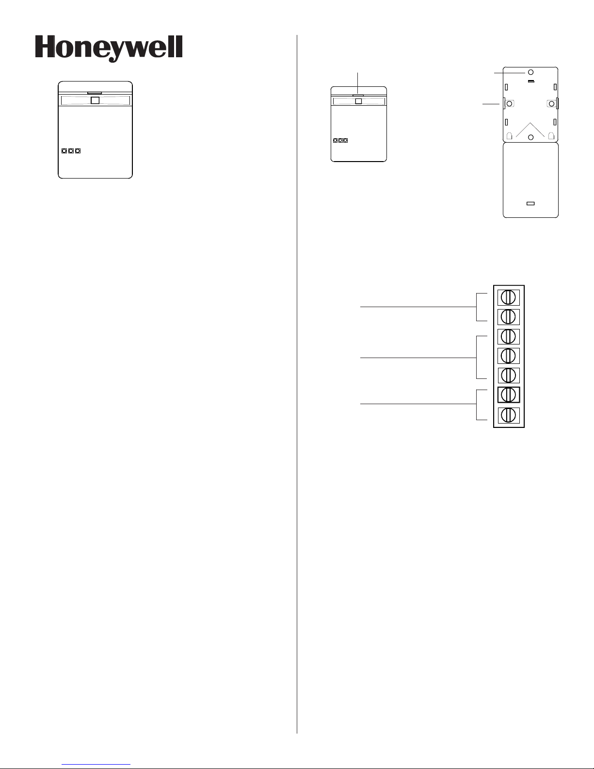
Pull the wiring into the unit through the back cover. Using the two mounting
screws, mount the rear housing at the desired location.
After removing screw at top of
unit, depress this latch to open
housing
For surface mounting
For corner mounting
(score and pull flap open)
REAR HOUSING
Knockouts
The FG-730 is a dual technology glassbreak detector that uses flex
detection and audio discrimination to detect breaking glass.
The flex and audio technologies are sensitive to different frequencies. The
flex technology is sensitive to ultra low frequencies, the type generated by
a blow to a glass window. The audio technology detects the frequency of
breaking glass.
The audio technology remains off until the flex technology detects a blow
to the glass. For an alarm condition to occur, the audio must detect the
frequency of breaking glass within a defined time-window after the flex
detects a blow to the glass. Because both technologies must detect and
verify glass breakage, false alarms are virtually eliminated.
FEATURES
.
Dual flex/audio technology
.
Low 10 - 14 VDC operation
.
Low 25 mA at 12 VDC current
draw
.
No adjustment on audio
.
Adjustment on flex detection
to fit characteristics of each
location
MOUNTING LOCATION
The FG-730 can be mounted on walls, in corners, even on false or suspended
ceilings. Refer to the guidelines below when selecting a mounting location.
.
The unit must have a direct line of sight to, and a clear view of,
the protected glass.
.
Locate the FG-730 within 30' (9 m) of the glass to be protected.
.
Curtains, blinds, and other window coverings will absorb energy
from breaking glass. Heavy curtains, for example, will effectively
block the sound signal. In these cases, mount the unit on the window
frame behind the window covering, or above the window. Make
sure to test the unit thoroughly for proper detection.
.
Do not mount the unit in front of air ducts or forced air fans, or
close to bells measuring 2" (5 cm) or larger in diameter.
MOUNTING PROCEDURE
Orient the unit as shown in Figure 1. Remove the screw located at its top.
While depressing the latch near the top of the unit, swing the front cover
forward. Use the back cover as a template to mark holes for the mounting
screws and wiring, then drill the holes.
.
Note: If you plan to corner-mount the unit, remove the printed
circuit board before marking and drilling holes for the mounting
screws.
.
Alarm memory
.
Indicator LEDs
.
Energized form C alarm relay
.
Circuit protection
.
Cover tamper switch
.
Noise burst rejection circuit
.
RFI immunity
.
UL listed
Figure 1
Mounting
the FG-730
WIRING
Observing the proper polarity, wire the unit as shown in Figure 2 (use 22
to 14 AWG). Reverse-polarity connections will not damage the unit.
Tamper
Form A (NC)
50 mA, 30 VDC
FRONT HOUSING
NC
C
NO
Alarm
Form C
500 mA max, 30 VDC max,
30 VA max
Power
10 - 14 VDC
25 mA, 12 VDC
Figure 2 FG-730 Terminal Strip
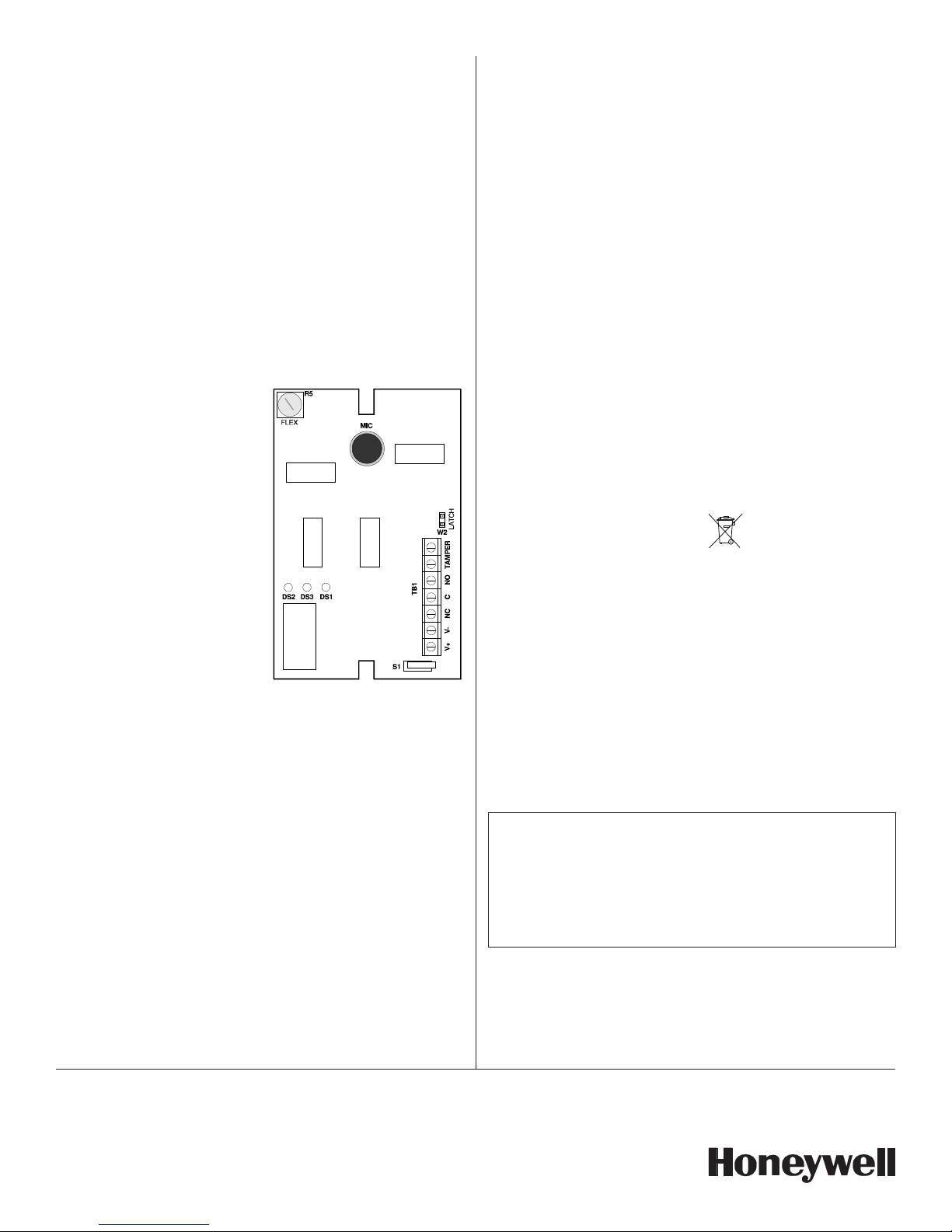
FLEX ADJUSTMENT
To adjust the flex technology: Use a screwdriver to set the flex sensitivity
control (R5) at MAXIMUM by turning it all the way clockwise. Refer to Figure
3 on the back side of this page.
Turn on any heating/air conditioning system in the vicinity and observe the
yellow flex LED (DS2) for approximately one minute. Excessive subsonic
(inaudible) noise typically produced by air handling systems may cause
the flex LED to flash randomly.
If it flashes randomly, turn the R5 control counterclockwise just until the
flashing stops.
TESTING THE FG-730
Use the FG-701 Glassbreak Simulator to test the FG-730 detector. The FG700 may also be used.
Activate the simulator in MANual mode at the farthest point of the glass to
be protected (30' maximum). If the green LED (DS1) on the detector
flashes, the audio technology will detect breaking glass at that distance.
Test the flex technology by carefully striking the glass with a cushioned tool.
If the yellow LED on the detector flashes, the flex technology will be sensitive
enough to detect a blow to the glass at that distance.
C
NC
V-
V+
Page 2
Testing the FG-730 (continued)
Switch the FG-701 simulator to the FLEX mode and generate a flex signal
by carefully striking the glass. The simulator will automatically generate a
burst of glass-break sound, and the red LED (DS3) on the FG-730 should
light to indicate an alarm condition.
See the FG-701 operating instructions for additional testing information.
FINAL TESTING
To ensure maximum protection against false alarms, activate any device in
the area that may automatically cycle: pumps, generators, heating/air
conditioning units, etc. If the cycling devices trigger an alarm, mount the
unit in a different location.
There is no need to relocate the detector if the cycling only briefly triggers
the flex technology (the yellow LED flashes).
ALARM MEMORY
The FG-730 is equipped with a
latching circuit for the alarm LED.
When the latching circuit is
activated, an alarm condition will
make the red alarm LED on the
units latch on. This feature is
particularly helpful in determining
which unit alarmed in a multiple
detector installation.
To activate the latching circuit,
install a jumper at position W2 on
the printed circuit board. Refer
to Figure 3. To reset the latched
alarm LED, remove then restore
power to the detector.
SPECIFICATIONS:
Range:
FG-730 30' (9 m)
Alarm relay:
Form C
500 mA max
30 VDC max
Tamper switch:
Form A (NC)
50 mA, 30 VDC
Power requirements:
10 - 14 VDC
25 mA, 12 VDC
Dimensions:
3.9" H x 2.4" W x 0.79" D
(98 mm x 61.5 mm x 20 mm)
Weight:
3 oz (85 g)
Operating temperature:
32o F to 120o F (0o C to 49o C)
(Indoor use environment)
Glass types:
1/8", 3/16", and 1/4" plate;
1/4" laminated, wired, and
tempered;
minimum size 10-7/8" x 10-7/8",
single pane
NOTE: The FG-730 should be tested at least once each year to
ensure proper operation.
Approvals:
UL listed
CE
To obtain applicable EU
compliance Declaration of
Conformities for this
product, please refer to
our Website, http://
www.security.honeywell.com/
hsce/international/index.html.
For any additional information
regarding the compliance of
this product to any EU
specific requirements, please
contact:
Honeywell Security &
Communications
Honeywell Security Quality Assurance Dept.
Newhouse Industrial Estate
Motherwell
Lanarkshire ML1 5SB
Scotland
United Kingdom
Tel: +44(0)1698 738200
Email:
UK64Sales@Honeywell.com
Note: The latching circuit has
absolutely no effect on the
alarm relay. The alarm relay
will continue to function as
normal.
For the latest U.S. warranty information, please go to: www.honeywell.com/security/hsc/resources/wa or
Please contact your local authorised Honeywell representative for product warranty information.
©
2004 Honeywell International Inc. • Honeywell, IntelliSense and DUAL TEC are registered trademarks of
Honeywell International Inc.
All other trademarks are the properties of their respective owners. All rights reserved.
Figure 3 Testing the
FG-730
Important: The FG-730 must be connected to a UL listed power
Due to the variation of acoustics in different environments, (i.e. ceiling
mount units, big open rooms, soft environments), all units must be
tested with the FG-701 Glassbreak Simulator. No unit should be
mounted outside the effective range of the simulator.
supply or UL listed control unit capable of providing a
minimum of four hours of standby power.
IMPORTANT NOTICE
All FlexGuard® Glassbreak Detectors
Ê5-051-169-006Š
5-051-169-00 7/14 Rev. J
 Loading...