

Page 1
FF-SNC
Safety Non Contact Switch
Instructions for use
IMPROPER INSTALLATION
• Consult with US and/or European safety agencies and
their requirements when designing a machine control,
interface and all control elements that affect safety.
• Strictly adhere to all installation instructions.
Failure to comply with these instructions could result
in death or serious injury.
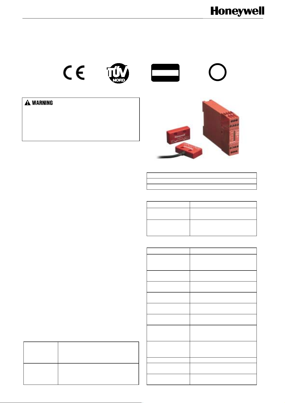
PRODUCT DESCRIPTION
The FF-SNC Honeywell safety non contact switch is a tamper
resistant safety system for monitoring machine guards. The
actuator being a passive component, the safety switch is the only
component that needs to be wired to the control unit and cannot be
defeated by a regular magnet.
Each system is made up of one or several safety switches,
actuators and a control unit. The Honeywell FF-SNC safety non
contact switches are designed in compliance with the requirements
of the EN 954-1 European Standard for Category 3 Protective
Devices.
The FF-SNC is especially suited for applications where perfect door
alignment can not be attained. The FF-SNC Series can be
mounted on sliding, hinged or removable machine guards. The
output of the control unit is triggered as soon as the distance
between the safety switch and the actuator is greater or equal to
8 mm/0.32 in. This switching distance compensates for the
machine vibration or a minor issue with the installation alignment.
The sensor and actuator small size makes it usable under tight
space requirements. The safety switches and the actuators provide
excellent chemical and mechanical resistance. Stainless steel
housing versions fulfil the requirements of the Food and Beverage
industry.
The FF-SNC400 safety control unit comes in a 75 mm / 2.95 in
package and can monitor up to 4 sensors.
The FF-SNC200 safety control unit with its 22,5 mm / 0.89 in width
will easily find a place in the electrical cabinet and can monitor
2 sensors. Both control units can be placed up to 100 m / 328 ft
away from the safety non contact switches. The indicators located
on the front cover of both control units provide individual door status
information.
The FF-SNC1EXT extension module can be added to the
FF-SNC400 or FF-SNC200 control unit and allows the
connection of 5 additional sensors.
APPROVALS
CE The product, packaging and
documentation of FF-SNC Series
products is CE mark following an
examination by TÜV.
cULus This product is pending approval at
Underwriters Laboratories Inc.
According to Canadian and U.S. safety
requirements.
Suitable for interfaces
up to
CATEGORY 3
per EN 954-1
U
®
CUSSTEDLI
L
(pending)
DIRECTIVES COMPLIANCE
Machinery Directive 98/37/EC
Low Voltage Directive 73/23/EC
Electromagnetic Compatibility Directive 89/336/EC
REGULATIONS COMPLIANCE
Regulation Title
OSHA 29 CFR
1910.212
OSHA 29 CFR
1910.217
General Requirements for
(guarding of) all Machines
Requirements and
Safeguarding of Mechanical
Power Presses
STANDARDS COMPLIANCE
Standard Title
EN 292 Safety of Machinery – Basic
Concepts, General Principles
for Design
EN 60204 Safety of Machinery – Electrical
Equipment of Machines
EN 954-1 Safety of Machinery – Safety
related parts of control system
EN 1088 Interlocking Devices associated
with Guards
ANSI B11.1 Construction, Care and Use of
Mechanical Power Presses
ANSI B11.2 Construction, Care and Use of
Hydraulic Power Presses
ANSI B11.19 Safeguarding Performance
Criteria for the Design,
Construction, Care and Use
ANSI/RIA R15.06 Safety Requirements for
Industrial Robots and Robot
Systems
UL 508 Industrial Control Equipment
UL 991 Test for Safety related Controls
employing solid state devices
NFPA79 Electrical Standard for Industrial
Machinery
107099-10-EN FR26 GLO 602 Printed in England
Page 2
SPECIFICATIONS
Switch
Operating temperature -10 °C to +55 °C / 14 °F to 131 °F
Connection to the control unit Max. Cable length: 100 m / 328 ft
Material ABS (FF-SNC1SA03PA) or Stainless Steel and Resin filled (FF-SNC1SA03PS)
Sensing range 5-7 mm / 0.20 – 0.27 in On; 8-12 mm / 0.32 – 0.47 in Off
Optimum gap1 mm
Standard cable length 3 m / 9.84 ft or 5 m / 16.4 ft
Sealing IP 67
Fixing 2 x (M4x20 mm) Tamper proof screws (supplied with the product)
Control unit / Extension module
Category Category 3 according to EN 954-1
Supply voltage 24 Vdc/Vac ± 15 % / 110 Vac ± 15 % (FF-SNC400R4 only)
Response time of the control unit 15 ms (with or without extension module)
Power consumption (including
6 VA (with or without extension module)
sensors)
Operating temperature -10 °C to + 55 °C / 14 °F to 131 °F
Storage temperature -20 °C to 60 °C / -4 °F to 140 °F
Output 2 NO + 1 NC contacts (4 A / 250 Vac; 2 A / 30 Vdc)
Restart Manual or automatic
Sealing IP 40 Housing, Terminals IP 20
Mounting 35 mm / 1.37 in DIN rail
LED indicators
FF-SNC200R2 control unit: Power, Run and 2 guard status indicators
FF-SNC400R4 control unit: 4 guard status indicators and selection indicators
Material Polycarbonate, red
Ordering information: Description Weight
FF-SNC200R2 24 Vdc/Vac Control unit for monitoring up to 2 gates: 0,235 kg / 0.517 lb
FF-SNC400R2 24 Vdc/Vac Control unit for monitoring up to 4 gates: 0,49 kg / 1.078 lb
FF-SNC400RE 110 Vac Control Unit for monitoring up to 4 gates: 0,63 kg / 1.386 lb
FF-SNC1SA03PA Safety switch + actuator: 3 m / 9.84 ft cable: 0,169 kg / 0.371 lb
FF-SNC1SA05PA Safety switch + actuator: 5 m / 16.4 ft cable: 0,255 kg / 0.56 lb
FF-SNC1SA03PS Safety switch + actuator: 3 m / 9.84 ft cable –
0,265 kg / 0.583 lb
Stainless Steel Housing
FF-SNC1ACS Actuator Only: Stainless Steel Housing 0,077 kg / 0.169 lb
FF-SNC1ACA Actuator Only : ABS Housing 0,028 kg / 0.061 lb
FF-SNC1EXT Extension Module 0,135 kg / 0.297 lb
MOUNTING DIMENSIONS (mm/in) for reference only
FIG 1. FF-SNC Control unit
H
W
A1DRBLDRBLDRBL
GATE 2
GATE 1
GATE 4 GATE 5
A2DRBLDRBL BL
D
GATE 3
DR
H
FSNC_1
FIG. 2. FF-SNCS1A03PS - FF-SNCS1A03PA
29 / 1.14
ø 4,2 / 0.16
ø 8,1 / 0.32
W
H
D
53 / 2.08
22 / 0.86
FF-SNC200R2
22,5 / 0.88
84 / 3.30
119 / 4.68
13,5 / 0.53
SIDE
6,4 / 0.25
FF-SNC1EXT
119 / 4.68
3 / 0.11
ø 4,2 / 0.16
ø 8,1 / 0.32
FF-SNC400R2
FF-SNC400RE
75 / 2.95
74 / 2.91
28 / 1.10
52 / 2.04
22 / 0.86
(in mm/in)
14 / 0.55
SIDE
6,4 / 0.25
3 / 0.11
2 107099-10-EN FR26 GLO 602 Printed in England
Page 3
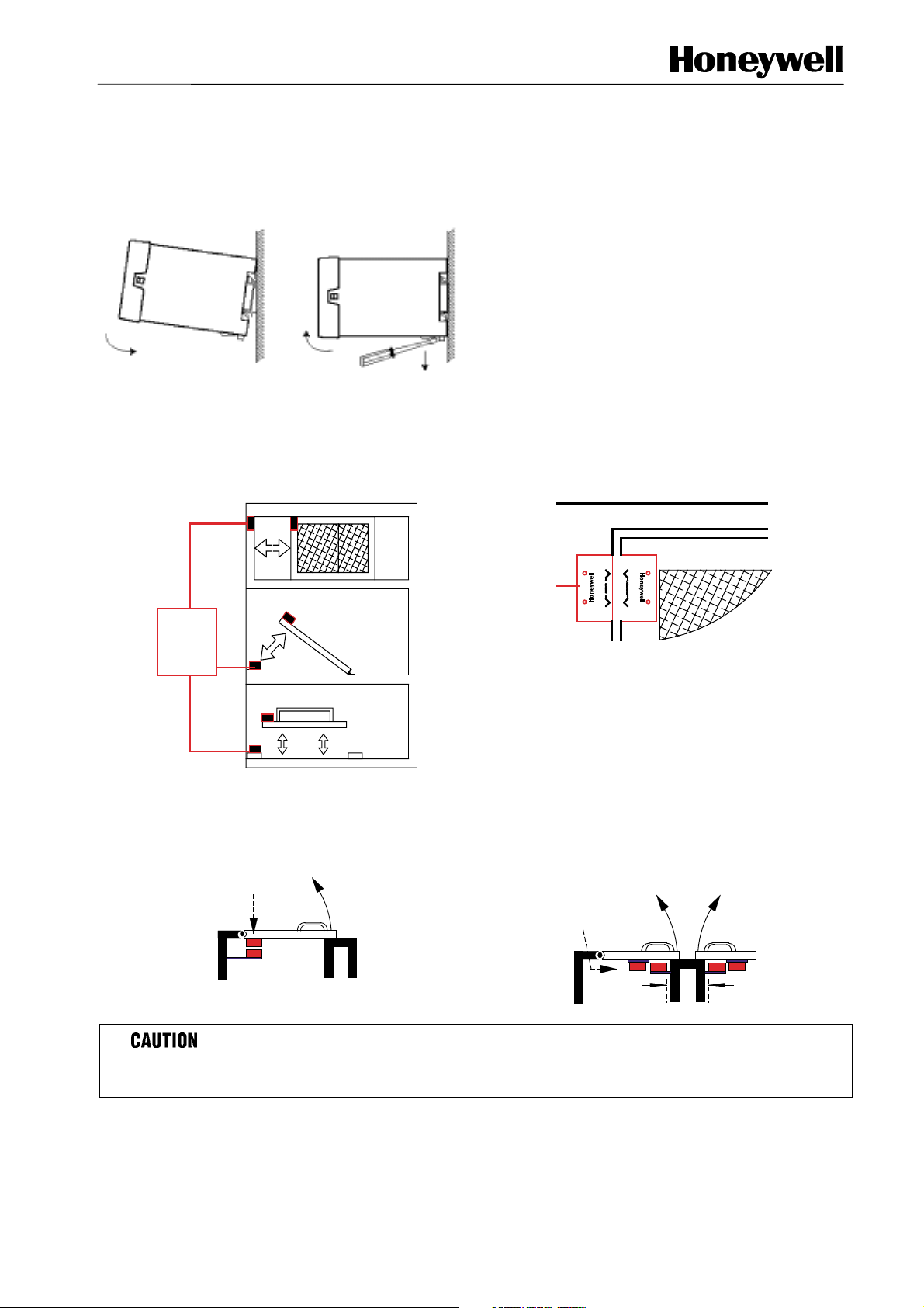
MECHANICAL INSTALLATION
The FF-SNC Control unit must be installed inside a NEMA 3 (IEC IP 54) rated enclosure or better. The module can be
clipped easily onto a 35 mm (1.38 in.) width DIN rail (see figure 3 for installation and removal).
FIG 3. INSTALLATION DIAGRAM
1. The FF-SNC control
unit is designed to fit
standard 35 mm /
1.37 in symmetric DIN
rail.
2. To remove: Place the tip
of a small screwdriver into
the white catch at the
bottom of the box (1) and
gently lever out.
This releases the retaining
clip and allows the unit to
be titled (2) and removed (3).
MOUNTING SAFETY SWITCH SENSORS
The FF-SNC safety swiches can be fitted to sliding, hinged or removable machine guards. Mount the fixed part of the
safety switch to the machine frame and the actuator on to the opening edge of the door ensuring that the targets on the
printed faces of the switches are aligned (see Fig. 4).
FIG. 4
FIG. 5
SLIDING DOOR
FF-SNC
HINGED DOOR
FF-SNC
FF-SNC
GUARD DOOR
LIFT OFF DOOR
FSNC_10EN
GUARD SWITCHES
The FF-SNC safety switch sensors have 2 fixing holes and are supplied with M4x20 mm Torx Proof screws to be specified.
FIG. 6. FIG. 7
WRONG
FSNC_4
CORRECT
Leave a 1 mm/0.039 in
gap to prevent damage
FSNC_3
FSNC_5
Min. 50 mm/1.97 in between actuators
as above
DO NOT enlarge the fixing holes!
Failure to comply with these instructions will result in product damage.
107099-10-EN FR26 GLO 602 Printed in England 3
Page 4

• Always try to mount the switch and actuator on non-ferrous material. Ferrous materials will reduce the switching distance.
• The sensors should be mounted with a gap of approximately 1 mm/0.039 in (Fig 7). When the guard is closed, this gives a
good level of lateral tolerance to allow for “gate sag” and freedom from nuisance tripping due to machine / guard vibration.
• Leave a minimum gap of 50 mm/1.97 in between actuators as above (Fig. 7).
IMPROPER HINGED DOOR INSTALLATION
On a hinged door, do not mount the switch and actuator close to the hinge (Fig. 6) in order to prevent the door from
being opened while the switch is still in the scanning range specifications (State ON).
Failure to comply with these instructions will result in death or serious injury.
IMPROPER SWITCH INSTALLATION
EN 1088 provides some mounting suggestions, see examples below.
When fixing the switches to a sliding door (see Fig. 8), ensure that when the door is opened (see Fig. 9), the switch is
not easily accessible, helping prevent the system from being overridden.
Failure to comply with these instructions will result in death or serious injury.
FIG. 8. FIG. 9.
FSNC_6
FSNC_7
Refer to the European standards EN 811, EN 953, EN 294.
IMPROPER EXTENSION MODULE WIRING AND SET UP
• NEVER use the FF-SNC1EXT extension module as a stand alone module. It must be connected to the
FF-SNC400R2, FF-SNC400RE or FF-SNC200R2 master module, to operate correctly.
• Generally speaking, do NOT use the FF-SNC1EXT extension module if the master module (FF-SNC400R2,
FF-SNC400RE or FF-SNC200R2) can support all sensors needed in the application.
• When use of the FF-SNC1EXT extension module is required, it should be connected to the last input available on
the master module, ie "gate 4" for the FF-SNC400R2 or FF-SNC400RE or "gate 2" on the FF-SNC200R2.
• If exceptionaly the FF-SNC1EXT extension had to be used although inputs available on the master module are not
all used, make sure the extension module is connected to the next available input. For example, if only 2 sensors
are connected on the FF-SNC400R2 4-gate master module, the sensors would have to be connected to "gate 1"
and "gate 2" inputs and the extension module would have to be connected to "gate 3".
• Selector switches on the extension module and on the master module should always be positioned to reflect and
match the exact number of inputs in use, whatever is connected to these inputs (a sensor or an extension module).
• When installing or modifying an FF-SNC system, ALWAYS test correct operation by opening and closing each gate
separately. When all gates are closed and the master module reset, the master module safety outputs 13-14 & 2324 should be ON. When any of the gates is opened, the safety outputs 13-14 & 23-24 should go OFF.
Failure to comply with these instructions will result in death or serious injury.
4 107099-10-EN FR26 GLO 602 Printed in England
Page 5

LID REMOVAL AND SWITCH SELECTION
MODE SETTING LED INDICATORS
FIG. 15. FF-SNC400R❏
❏ active gate selection
❏❏
ELECTRICAL SHOCK
• Remove power from FF-SNC switches and before
setup. Ensure that installation is performed by
qualified personnel.
Failure to comply with these instructions could
result in death or serious injury.
This module offers the capability to function in the
automatic start mode or manual start mode. To set the
desired mode of operation, insert the start pushbutton between terminals X1/X2 for manual start
mode or insert a jumper between X1/X2 for
automatic start mode to function.
LID REMOVAL
The central part of the
FF-SNC lid (1) is
FIG. 10.
removable. Using a small
screwdriver in the recess
(2) gently prise the lid
upwards.
21
This allows access to the
Guard Selector Switch (See
Fig. 11 to 13) and to the
automatic and restart mode
selector switch.
SWITCH SELECTION
Using the GATE SWITCH
SELECTOR Switch, set the
FF-SNC to the required
number of inputs.
NOTE: the number of
Active Gate Selection
A1
G2
G1
FF-SNC200R2
31 13BL23
DR
A131X113BL23DR
GATE 1
GATE 1
G2
G1
inputs (safety switches)
must match the gate
selector setting. Any
difference will prevent the
system from operating.
A132X214BL DR
FIG. 11.
Selector
switch
down for 1
GATE 2
24
GATE 2
A132X214BL DR
24
FIG. 12.
Selector switch
up for 2 gate
operation
gate
operation
Automatic/Manual
restart:
Using the AUTOMATIC /
MANUAL SELECTOR
Switch, set the FF-SNC to
the required restart mode.
31 13BL23
A1
A
M
GATE 2
A132X214BL DR
GATE 1
DR
A131X113BL23DR
GATE 1
A
M
GATE 2
A132X214BL DR
24
24
Auto
Manual
FF-
SNC200
A
(up)
M
FF-
SNC400
A
(down)
FIG. 13.
Selector
switch up for
automatic
restart
FIG. 14.
Selector
switch down
for manual
restart
(down) M (up)
Gate
Selector
Operation
Switch
1 Gate Operation
Yellow LED No.1 will illuminate when
234
gate switch 1 is closed
When no Green LED's are illuminated
only the first gate input is activated
2 Gate Operation
2
3
Yellow LED's No.1 & No.2 will illuminate
when the corresponding gate switch is closed
4
The top Green LED will be illuminated
to show 2 gate inputs are activated
3 Gate Operation
23
Yellow LED's No.1, 2 & 3 will illuminate
when the corresponding gate switch is closed
4
The top 2 Green LED's will be illuminated
to show 3 gate inputs are activated
4 Gate Operation
234
FSNC_9
Yellow LED's No.1,2,3 & 4 will illuminate
when the corresponding gate switch is closed
All three Green LED's will be illuminated
to show all 4 gate inputs are activated
FIG 16. FF-SNC1EXT active gate selection*
Gate
Selector
Operation
Switch
1 Gate Operation
G2
Yellow LED No.1 will illuminate when
G3
gate switch 1 is closed
G4
When no Green LED's are illuminated
only the first gate input is activated
G5
G2
FSNC_24
FSNC_25
*If an extension module is connected, it has to be taken
into account when selecting active gates.
2 Gate Operation
Yellow LED's No.1 & No.2 will illuminate
G3
when the corresponding gate switch is closed
G4
The top Green LED will be illuminated
to show 2 gate inputs are activated
G5
G2
3 Gate Operation
Yellow LED's No.1, 2 & 3 will illuminate
G3
when the corresponding gate switch is closed
G4
The top 2 Green LED's will be illuminated
to show 3 gate inputs are activated
G5
4 Gate Operation
G2
Yellow LED's No.1,2,3 & 4 will illuminate
G3
when the corresponding gate switch is closed
G4
All three Green LED's will be illuminated
to show all 4 gate inputs are activated
G5
5 Gate Operation
G2
Yellow LED's No.1,2,3,4 & 5 will illuminate
G3
when the corresponding gate switch is closed
G4
All four Green LED's will be illuminated
to show all 5 gate inputs are activated
G5
FSNC_14
FSNC_15
107099-10-EN FR26 GLO 602 Printed in England 5
Page 6

Safety Distance Calculations per US ANSI / OSHA standard
Ds = K(Ts + Tc + Tr ) + Dpf
With:
Ds = minimum safe distance between safeguarding device and hazard
K = speed constant: 1,6 m/sec (63 in/sec) minimum based on the movement being the hand/arm only and the body
being stationary (a greater value may be required in specific applications and when body motion must also be
considered)
Ts = worst stopping time of the machine/equipment
Tc = worst stopping time of the control system
Tr = response time of the safeguarding device including its interface (Tr for interlocked barrier may include a delay
due to actuation. This delay may result in Tr being a deduct– negative value).
Dpf = the “Depth penetration factor” is the maximum travel towards the hazard if the guard can be opened a certain
width or amount before a stop is signaled.
Dpf values from OSHA O-10 Table
If the maximum width or diameter of the opening is less
than or equal to (mm/in):
6,4 / 0.25 12,7 / 0.5
9,5 / 0.375 38,1 / 1.5
12,7 / 0.5 63,5 / 2.5
15,9 / 0.625 88,9 / 3.5
19,1 / 0.75 139,7 / 5.5
22,2 / 0.875 165,1 / 6.5
31,8 / 1.25 190,5 / 7.5
38,1 / 1.5 317,5 / 12.5
47,6 / 1.875 393,7 / 15.5
54,0 / 2.125 444,5 / 17.5
152,4 / 6 800 / 31.5
Above 152,4 / 6 Not allowed
Example: Dpf = 0,5 when the guard can be opened up to, but less than 6,4 mm / 0.25 in before issuing a stop
command. Dpf = 444,5 mm / 17.5 in if the guard can be opened 54 mm / 2.125 in. At no time can the opening be
greater than 152,4mm / 6 in before issuing a stop command.
For more information, refer to the US regulations and standards (OSHA 29 CFR 1910.212 & 1910.217, ANSI B11.19
and ANSI/RIA R15.06).
Dpf equals (mm/ in.)
6 107099-10-EN FR26 GLO 602 Printed in England
Page 7

WIRING DIAGRAMS
(B)
y
FIG. 17.
24 V
(+)
24 V
(-)
FIG. 19.
FF-SNC200R2 FF-SNC400R2/FF-SNC400RE
FIG. 18.
+
GS1
F1
A1 X1 BL DR 31 13 23
GATE 1
POWER
IND 1
IND 2
RUN
GATE 2
A2 X2 BL DR 32 14 24
GS2
K1 K2
F2
K1
K2
(B)
Mechanical
Safety
Switches
Emergency
Stop
-
or
Manual
reset
K1
K2
(A)
FSNC_16EN
A1
S13 S23
X1 BL DR BL DR 31 13
POWER
RUN
A2
S14 S24
X2 BL DR BL DR 32 14 24
GS1 GS2
GATE 2 GATE 1
DE-SELECT
GATE 2
GATE 3
GATE 4
GATE 4 GATE 3
GS3 GS4
F1
F2
23
K1 K2
Wiring diagram with FF-SNC1EXT Extension Module
FF-SNC400R2
Control Unit (24 Vdc)
GS1 GS2
A1
S13 S23
X1 BL DR BL DR 31 13 23
GATE 2 GATE 1
1
POWER
DE-SELECT
GATE 2
2
RUN
3
GATE 3
4
GATE 4
S14 S24
X2 BL DR BL DR 32 14 24
GATE 4 GATE 3
A2
GS3
F1
K1 K2
F2
K1
K2
(A)
Manual
Reset
(Momentary
Push-Button)
K1
K2
24 Vdc
FF-SNX1EXT+
FF-SNC400R2
8 Gate safety system
with optional
mechanical switch
or E-Stop input
and Manual Reset
24 Vdc
+
-
FF-SNC1EXT
Extension Module
GS1
GS2 GS3
A1 BLDR
BLDR BLDR
GATE 1
GATE 2 GATE 3
POWER
2
3
4
5
GATE 4
GATE 5
A2 BLDR
BLDR BLDR
GS4
GS5
(B)
Mechanical
IND 1
safety switch
or E-Stop
IND 2
IND 3
IND 4
IND 5
K1
K2
(A)
Manual
Reset
K1
K2
FSNC_17EN
FF-SNC1EXT
Extension Module
GS1
GS2 GS3
A1 BLDR
BLDR BLDR
GATE 1
GATE 2 GATE 3
POWER
GATE 4
GATE 5
A2 BLDR
BLDR BLDR
GS4
FF-SNC200R2
Control Module
GS1
F1
F2
A1 X1 BL DR 31 13 23
IND 1
IND 2
IND 3
IND 4
IND 5
GATE 1
POWER
IND 1
IND 2
RUN
GATE 2
A2 X2 BL DR 32 14 24
K1 K2
K1
K2
(A)
Manual
Reset
(Momentary
Push-Button)
K1
K2
24 Vdc
+
FF-SNC400R2
2 x FF-SNC1EXT
10 Gate safety system
with Manual Reset
24 Vdc
-
FF-SNC1EXT
Extension Module
GS1
GS2 GS3
A1 BLDR
BLDR BLDR
GATE 1
GATE 2 GATE 3
IND 1
POWER
IND 2
IND 3
IND 4
IND 5
GATE 4
GATE 5
A2 BLDR
BLDR BLDR
GS4
GS5
(A) if the automatic restart is set, X1 and X2 must be jumpered for correct operation.
If a Mechanical Safet
operation.
Switch or an Emergency Stop is not used, S13/S14 and S23/S24 must be jumpered for correct
APPLICATION NOTES
Up to 28 gates can be protected, using extension modules.
The extension module must be connected to the BL/DR terminals corresponding to the last gate on the master module.
FSNC_23EN
107099-10-EN FR26 GLO 602 Printed in England 7
Page 8

WARRANTY AND REMEDY
Honeywell warrants goods of its manufacture as being
free of defective materials and faulty workmanship.
Contact your local sales office for warranty information.
If warranted goods are returned to Honeywell during
the period of coverage, Honeywell will repair or replace
without charge those items it finds defective. The
foregoing is Buyer’s sole remedy and is in lieu of all
other warranties, expressed or implied, including
those of merchantability and fitness for a particular
purpose.
While we provide application assistance, personally
and through our literature and the Honeywell Website,
it is up to the customer to determine the suitability of
the product in the application.
Specifications may change at any time without notice.
The information we supply is believed to be accurate
and reliable as of this printing. However, we assume no
responsibility for its use.
SALES AND SERVICE
For application assistance, current specifications,
pricing or name of the nearest Authorized Distributor,
contact a nearby sales office or call:
TELEPHONE
+ 61 (0) 2 9370 4500 Australia
+ 1-800-737-3360 Canada
+ 33 (0) 1 60 19 80 40 France
+ 49 (0) 69 8064 444 Germany
+ 34 91 313 61 00 Spain
+ 1-815-235-6847 International
+ 44 (0) 1698 481 481 UK
+ 1-800-537-6945 USA
FAX
+ 61 (0) 2 9370 4525 Australia
+ 1-800-565-4130 Canada
+ 33 (0) 1 60 19 81 73 France
+ 49 (0) 69 8064 442 Germany
+ 34 91 313 61 29 Spain
+ 44 (0) 1698 481 276 UK
+ 1-815-235-6545 USA
INTERNET
http://www.honeywell.com/sensing/
info.sc@honeywell.com
EC DECLARATION OF CONFORMITY
© 2002 Honeywell International Inc. All rights reserved
Honeywell
21, chemin du vieux chêne
38240 Meylan
9OO1ISO
AFAQ N 1994/2213
France
107099-10-EN FR26 GLO 702 Printed in England
E
C
E Net
Q
U
A
L
I
F
T
I
R
E
D
M
E
T
S
I
T
Y
S
Y
 Loading...