

Page 1
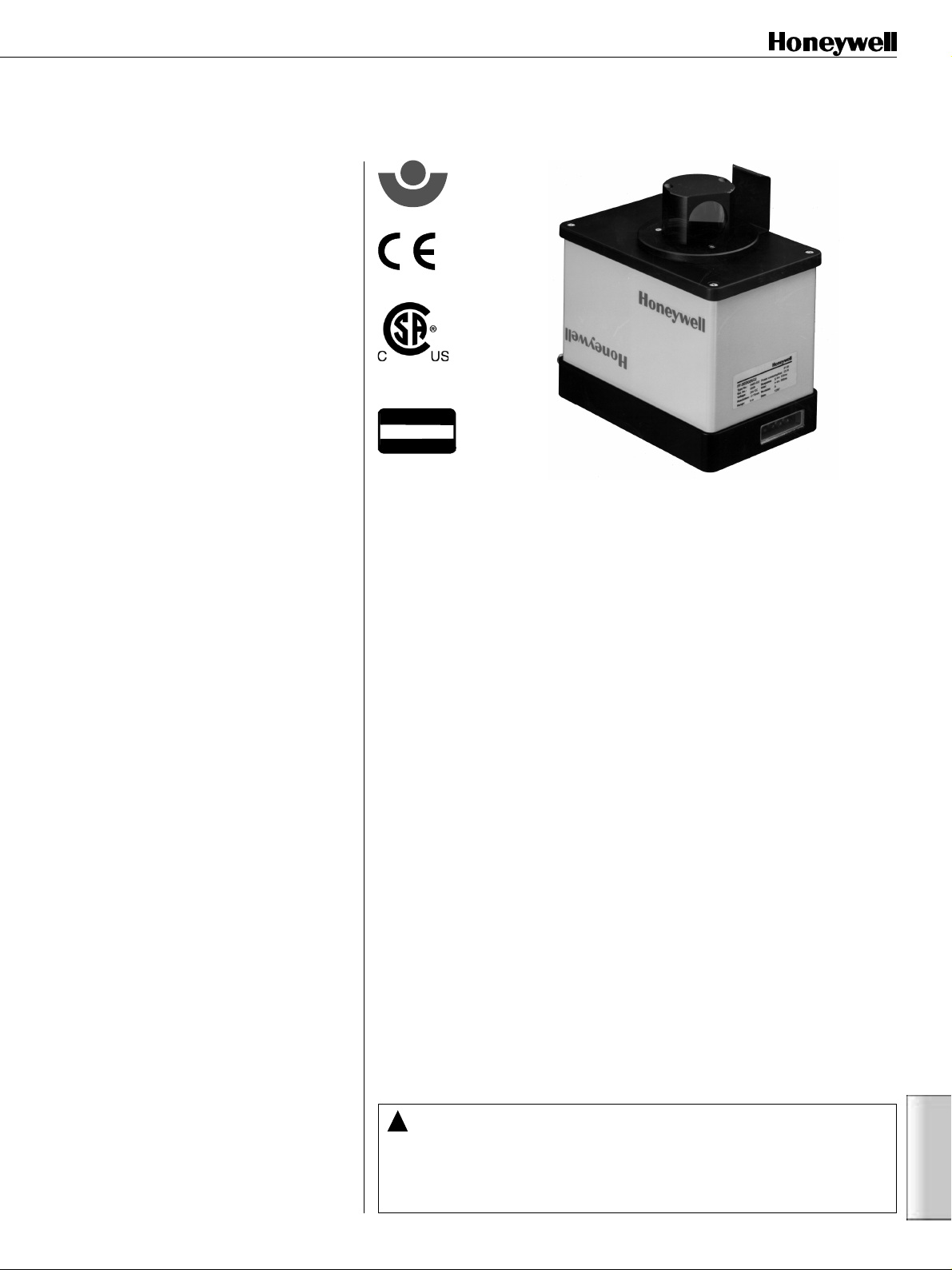
Category 3 Safety laser scanner
Two zone programmable area control
FF-SE Series
FEATURES
• No touch detection system in
compliance with the requirements of
IEC/EN 61496 part 1 and pr EN 61496
part 3 for Type 3 equipments
• Meets applicable parts of ANSI B11.191990 standard and OSHA 1910.212
regulations for Control Reliability
• Objects and people protection
2
• Surveillance area size up to 262 m
2
2820 ft
/
• Class 1 infrared Laser beam, invisible
and harmless to the eye
• Easy to install: a single device, a single
cable
• Detection of a unique inner failure per
EN 954-1
• Fast and accurate configuration of the
surveillance areas around the dangerous
zone with a computer and user friendly
software
• The shape of the protection zones fits
any environment (Teach-in option for
zone definition)
• Scanning angle: up to 300°
• Free rotating head, making it a self-
cleaning optical system
• Permanent self-checking of the beam
status with fixed test target
• External user defined test target
possibility to ensure correct positioning
of the laser during machine operation
• Response time: 0.280 s
• Surveillance range: 10 m / 32.8 ft
• Detection range: 6 m / 19.7 ft
• Resolution: 70 mm / 2.8 in
at 6 m / 19.7 ft
TYPICAL APPLICATIONS
• Horizontal detection (like a sensitive
mat) of people or objects
• Anti-collision system for AGVs
BIA
Berufsgenossenschaftliches
Institut für
Arbeitssicherheit
(Pending)
Approved as
Type 3
per IEC/EN 61496-1
The FF-SE laser scanner from Honeywell is a revolutionary product in the world of
industrial safety. This device combines radar and laser principles to scan pre-defined zones around dangerous machinery or moving vehicles. In case of intrusion
in these zones, output relays are immediately opened, eliminating the danger.
An infrared class 1 laser beam strikes a mirror rotating at 8 Hz, allowing it to sweep
a 300° area. Any object with a minimum reflectivity of 1,8% (black target) will be
detected in a 6 m / 19.7 ft radius. Two safety levels may be set through two zones
that can have any shape:
• “alarm zone”, in a 10 m / 32.8 ft radius around the FF-SE
• “safety zone” in a 6 m / 19.7 ft radius
These two zones are defined using the software (ordered separately), running on a
computer connected to the FF-SE, which allows the areas to be protected to be
displayed on the screen. The two zones correspond to two independent outputs,
allowing multiple applications:
• the alarm zone can be used to trigger an acoustic or light signal when a person
approaches, which indicates that there is a close danger, allowing the intruder to
withdraw without stopping the machine.
• the safety zone is used to trigger the immediate stopping of the machinery
(2 safety NO contacts).
Restart is automatic after clearing the zone. Use additional safety control module if
manual restart is needed.
This system is unique because of its small resolution (0,5° in angle) and its excellent precision, while covering a wide area (262 m2 / 2820 ft2). The FF-SE has been
designed in agreement with the pr EN 61496-3 that will soon be brought into effect
for this new kind of detecting device.
FF-SE Series
External and internal surveillance systems make it a Type 3 optoelectronic protective system. Its self-cleaning optical head and its good immunity to pollution guarantee a superior reliability.
!
WARNING
MISUSE OF DOCUMENTATION
• The information presented in this product sheet (or catalogue) is for reference only. DO NOT USE this document as system
installation information.
• Complete installation, operation and maintenance information is provided in the instructions supplied with each product.
Failure to comply with these instructions could result in death or serious injury.
•
Industrial Safety Products
• 153
FF-SE
Page 2
FF-SE
• Objects and people protection
BIA
Berufsgenossenschaftliches
Institut für
Arbeitssicherheit
• Scanning angle up to 300°
2
• Surveillance up to 262 m
/ 2820 ft
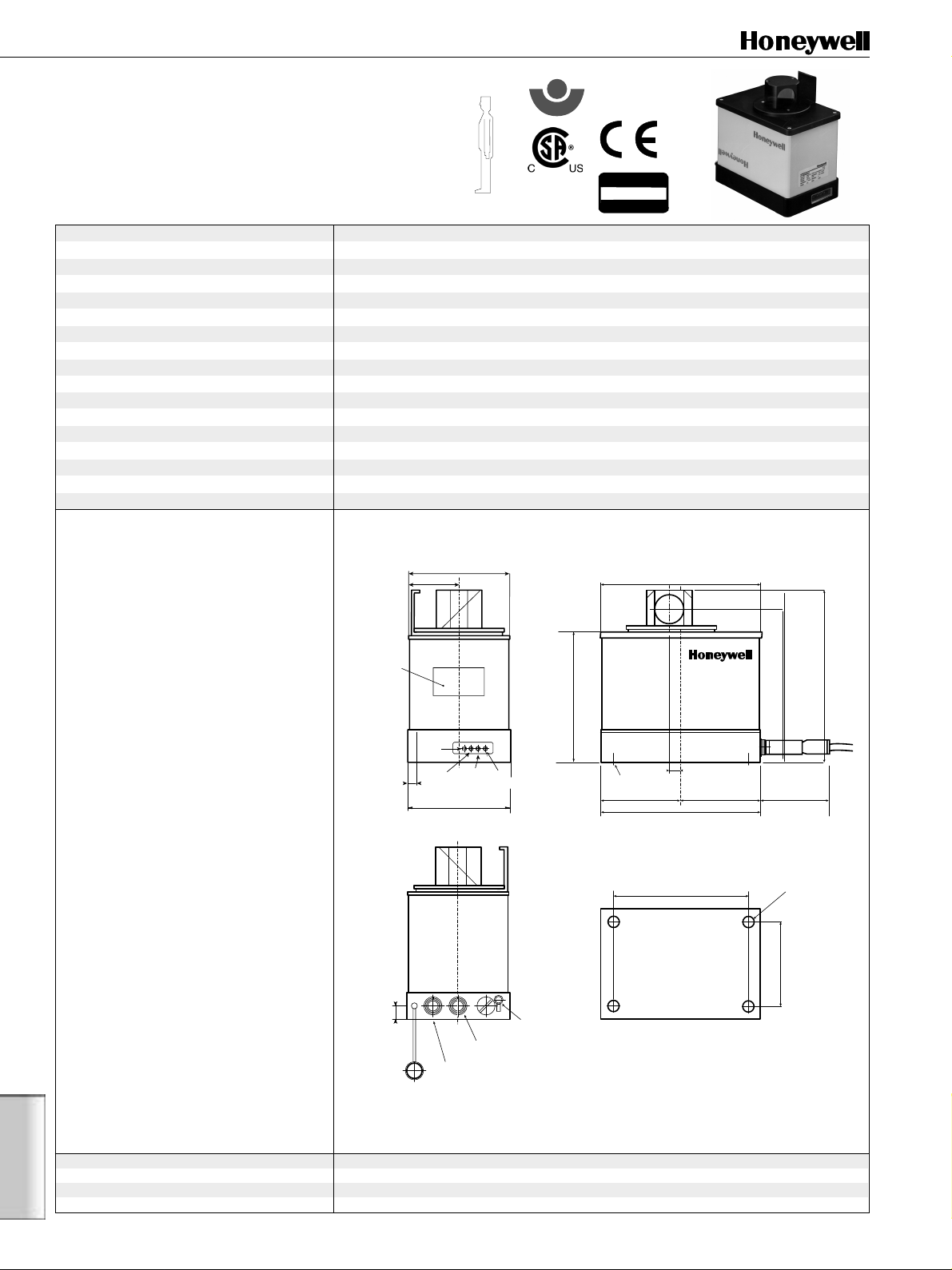
Dimensions in millimeters / inches, meters / feet, weights in kg / lbs
Features Power supply 24 Vdc, ± 15%
Consumption 0,75 A at 24 Vdc, rush at startup: 2 A during 100 ms
Measure and detection angle 300°
Detection distance Black target (1,8%): 6 m /19.7 ft
Head spinning frequency 8 Hz, ± 5%
Status display
Emitting source Infrared laser LED, 905 nm, ± 30 nm
Beam divergence 0,9°
Safety class
Protection class IP 65 (NEMA 4, 13)
Operating temperature 0 °C to 50 °C / 32 °F to 122 °F
Storage temperature -20 °C to 70 °C / -4 °F to 158 °F
Shock and vibration resistance According to IEC 68
2
(Pending)
Outputs 3 relay outputs, free of potential: 2 A / 48 V
Green:
safety zone free •
Red
: safety zone occupied •
Interface RS 232, V.24, 19200 Baud
Sensor:
Type 3 according to IEC/EN 61496-1
Material
Casing
: Aluminium •
Colour Yellow paint RAL 1021
Approved as
Type 3
per IEC/EN 61496-1
(1)
•
Laser
Connector
Yellow:
alarm zone occupied - Diagnostic
(2)
: Class 1
according to IEC 825-1
: Steel
Ordering information
FF-SEDGE6G2-1 Sensor kit
112 / 4.41 in
54 / 2.13 in
172 / 6.77 in
(Sensor + power cable)
and
FF-SEZ6SOFT2 Software kit (Diskette + PC cable)
Type plate
Accessories:
FF-SEZ6BRAC3 Mounting bracket
FF-SEZ6PLAT Mounting plate
FF-SEZ6POST Post supporting the bracket
Remarks
(1) Category 3 per EN 954-1.
FF-SE
(2) No special limitation of use in the USA or in
13,5 /
0.53 in
10 / 0.39 in
Protection cap
Interface
interface
Green
SAFETY
Red
SAFETY
Binder
Yellow
ALARM
LED
112 / 4.41 in
24 Vdc
Signal Fuse
Binder
Yellow
DIAGNOSTIC
3.15 A
PE connection
Type 132,5 ± 1 / 5.22 in
Mounting holes
M4 x 10 (4x)
View from the bottom
Position of the mounting holes
144 ± 0,2 / 5.67 in
Europe.
Infrared beam radius At 6 m / 19.7 ft: 100 mm / 3.9 in • At 10 m / 32.8 ft: 170 mm / 6.7 in
Beam Increment 0,5°
Response time t1 280 ms (including relays)
Device weight 3 kg / 6.61 lbs
Optical axis
10,5 / 0.41 in
172 / 6.77 in
155,5 ± 1 / 6.13 in
175,5 ± 1 / 6.91 in
==
approx. 60 / 2.36 in
ø 4,5 / 0.17
± 0,2
86 ± 0,2 / 3.39 in
154 •
Industrial Safety Products
•
FF-SE Series
Page 3

RS232
14 pins
PC RS232 FF-SE
1
White
Brown
Pink
Black
Yellow
Green
E
6
2
7
3
8
4
9
5
G
P
R
L
O
S
J
N
T
M
U
A
C
CTS
TxD
RxD
RESTART
RESET
GND
RTS
Tolerance and detection distances
i
n
w
g
e
i
V
Alarm zone
o
i
n
t
c
z
e
t
e
D
Safety zone
FF-SE
User defined
test target
60˚
Fixed test target
Installation distance
S
z
o
n
e
o
n
e
6 m/
19.7 ft
10 m/
32.8 ft
300˚
The protection zone is made up of 600 beams. Each beam receives a signal corresponding to a distance measured using the
light time of flight principle, whatever the reflectivity of the target. If this signal goes below a user defined threshold during
the surveillance, it means that an object is present in the protection area. Consequently, the corresponding relay is opened.
The surveillance area includes an alarm zone and a safety zone,
that are user-defined. Both may have an irregular shape which
corresponds to the environment.
Applications: a greater flexibility
The FF-SE being an optoelectronic detecting device, it has a no
touch detection and therefore brings more flexibility on site. Its
principle of diffuse reflection simplifies the installation, compared to the traditional emitter/receiver pair of light curtains.
The protection zones do not need any additional fixture (wall,
fence, door...) since the FF-SE covers a 300° angle and adapts
to existing obstacles. Installation costs are reduced to a minimum and the working position is easily accessible since the
protection is a no-touch type.
H
S ≥ V (t1 + t2) + (L - 0.4 H) + E
Where:
• S: Distance (mm / in)
• t1: Response time of the FF-SE (See technical
specifications)
• t2: Stopping time of the machine (s); i.e. the time interval
necessary to stop the machine, after the protection
device has emitted the stop signal
• L: 1200 mm / 47.28 in
• H: Height of the beam from the ground,
300 ≤ H ≤ 1000 mm / 11.82 ≤ H ≤ 39.4 in
• V: Penetration velocity (mm / s or in / s)
( V = 1600 mm / s in Europe) V = 63 in / s in USA
• E: Maximum Error in measurement (see technical
specifications)
2
4
5
13
8
7
6
In case of a change in the machine or production floor layout,
the FF-SE can adapt very quickly by a re-configuration. The
FF-SE is not linked to any particular set up or machine: it is
exchangeable just by programming.
Compared to a usual safety device (light curtain, safety mat,
door...), the FF-SE includes two protection zones which is a
great asset: the alarm zone, used as an early warning zone,
allows a signal to an intruder that he is close to a dangerous
zone and that his movement is about to stop the machine.
There is still time for the individual to change direction and
avoid a stoppage of the equipment that can be costly if it
occurs often. By avoiding unnecessary stoppage, the FF-SE
increases the production lines productivity without decreasing
the safety: it protects just what is needed.
Computer connection
G
E
RP
O
S
JC
T
N
UM
L
A
Pin number Signal Function
1 24 V Power 24 Vdc supply
2 GND24 Ground 0 Vdc supply
3 SAFETY 2.1 DETEC2 Safety 2 relay output
4 SAFETY 2.2 DETEC2 Safety 2 relay output
5 SAFETY 1.1 DETEC1 Safety 1 relay output
6 SAFETY 1.2 DETEC1 Safety 1 relay output
7 ALARM1 ALARM relay output
8 ALARM2 ALARM relay output
SHIELD PE Protection earth
FF-SE Series
•
Industrial Safety Products
FF-SE
• 155
Page 4

Software
The Honeywell software kit allows the protection zones to be
easily programmed into the sensor. This software runs under
any PC (286 or more), under MS DOS. The FF-SE is linked to the
PC through the serial port (RS232 format) and a cable supplied
with the software kit. The custom zone definition can be
achieved through 3 different methods that can be combined:
• with the mouse, by clicking on end points forming the limit of
the protection field;
• with the keyboard, by plotting points with the cursor keys;
• with a text editor in which the end points are defined by their
coordinates;
Defining the protection zones is easy since obstacles are displayed on the screen: they are seen in real time.
Using a PC also allows to store several configurations on a disk,
that can be retrieved in a few seconds into the sensor. One can
therefore define different shapes according to different situations and transmit them into the sensor whenever needed.
Once the settings are downloaded into the sensor, it is a
standalone device that will keep all zone definitions and parameters in a permanent memory, even if the power is cut. Access
to this memory and to zone definition is protected by a password. The program also has other features: real time profile
measurement, sensor simulation to get familiar with it, surveillance of the zones with intrusion time display.
Graphic screen
Defining the zones with the editor
Self-check
A fixed test target is mounted on top of the housing to ensure
the beam self-check: this takes away 60° off the scanning angle
to perform various checks: contamination of the lens, accuracy
of the distance measurements, status of the beam...
An external test target possibility ensures the correct positioning of the sensor and guarantees the safety if its position is
changed since the definition of the zones depend on the position of the sensor. The rotating head is self-cleaning and therefore is much less sensitive to pollution as other fixed-window
devices. The internal angular coder is controlled by a “surveillance circuitry”, as are the relays.
FF-SE
156 •
Example of electrical connection
Dangerous
machine
FF-SE
Industrial Safety Products
Alarm device
Switching device
SAFETY signals
ALARM signal
Interface
•
Switching device
Serial port
PC
FF-SE Series
Page 5

Connection diagram
(+)
Emergency
Stop P/B
Honeywell FF-SE
1
Safety Laserscanner
Safety
Safety
Output 1
Output 2
3456 7 8
Alarm
Output
2
PE
Signalling
K3
K3
A1
(+)S11S12S22
FF-SRS5935:
Setting of internal switches S1
and S2:
S1: "With cross fault detection"
Power
K2
K3
S2:"Manual restart" mode
A2
S33S
(-)
(-)
Start
Installation
The FF-SE can be installed in various configurations. It does
not need any receiver nor separated reflector. When mounted
horizontally, it replaces light curtains or safety mats by offering
a better coverage and an increased flexibility. Its small size
allows installations in most of existing sites. The laser beam is
an invisible Class 1 laser, therefore it is not harmful and does
not disturb workers. A unique connector links the sensor to the
power supply and the devices connected to the 3 output relays
(alarm, safe 1 and safe 2), making connections with the sensor
very easy.
13 23 33 41
S1
S2
Internal Switches
S21
14 24 34 42
PE
34
Machine Control
Minimum distance
Honeywell
FF-SRS5935
Minimum distance
above the floor
B
e
z
e
i
c
h
T
y
p
N
r
.
S
e
r
.
N
r
.
150 mm /
5.91 in
n
u
n
g
LA
04
D
85
AR
00
2
00
D
0
0
/D
O
06
W
0
R
S
e
6
v
.
A
B
j
.
9
6
Scanning range
10 m / 32.8 ft
For AGVs
Weight and speed of AGVs in industrial environments can represent a certain danger for the workforce. The FF-SE can be
installed on these AGVs to ensure people safety: due to its long
range, it can stop the AGV before the obstacle, even if its speed
is high.
The two distinct zones can be used in an elegant way:
The alarm zone, with its 10 m / 32.8 ft range, acts as a slowing
down system: if something is detected in the zone, the AGV will
slow down and emit a warning signal to make the way free
again.
The safety zone, with its 6 m / 19.7 ft range, acts as an emergency stop: the AGV will immediately be stopped when an object is detected in this zone.
Knowing the AGV stopping distance and the response time of
the safety chain, it is possible to calculate the limits of these
zones optimally.
FF-SE Series
•
Industrial Safety Products
Normal speed
Slowing down
Complete stop
• 157
Safety zone
Alarm zone
Safety zone
Alarm zone
No intrusion
Intrusion
in the alarm zone
Intrusion
in the safety zone
Safety zone
Alarm zone
FF-SE
Page 6

Accessories
•FF-SEZ6BRAC3 Mounting bracket: It reinforces the
protection in installations where the sensor could be reached
by humans or vehicles. It allows head up or down mounting.
The bracket can be mounted on a vertical surface from behind
thanks to 4 M6 holes. There are 2 adjustable screws that allow
an adjustment of the scanning plane (±8°) in X, ± 4° in Y, so as
to allow an accurate placement of the beam, especially in
multiple device configurations.
Dimensions in millimeter/inches
200 / 7.88
50 /
1.97
89,5 /
r=10
30 /
95 / 3.74
105 /
165 / 6.50
13 /
0.51
1.18
4.13
3.52
89,5 / 3.52
200 / 7.88
2xr=10
42 /
1.65
90 /
3.54
60 /
116
42 /
1.65
4 M12 holes
4 ø6 holes for wall mounting
110,5 / 4.35
4xr = 10
1 ø6 hole
95 /
3.74
2 ø9 holes
2xr=11
±8˚ ±4˚
125 / 4.92
230 / 9.06
110 / 4.33
28/
1.10
60 /
60 /
30 /
1.18
2.36
2.36
135 / 5.32
mini. r
4 ø6 holes
1 ø 6 hole
86 / 3.38
5 /
0.19
•FF-SEZ6PLAT Mounting plate: Mounting plate to mount the
scanner on horizontal ground.
•FF-SEZ6POST:
This post is designed to support the mounting bracket
FF-SEZ6BRAC3. This allows an adjustment of the scanning
plane height. The scanning plane can be adjusted from
300 mm up to 700 mm / 11.82 in to 27.58 in. The bracket can
also be rotated around the post. A collar holds the bracket to
the post and slides on the post. The bracket can be mounted
up or down, so that the laser scanner head is either up or
down.
226 / 8.90
130 / 5.12
ø295 /11.62
overall: 700 / 27.58
FF-SE
•FF-SEZ6SOFT2: The Honeywell software kit allows sensor
programming and setup. It is supplied with a manual
explaining how to use it and an RS232 cable for PC
connection.
158 •
Industrial Safety Products
300 / 11.82
•
FF-SE Series
 Loading...