

Page 1
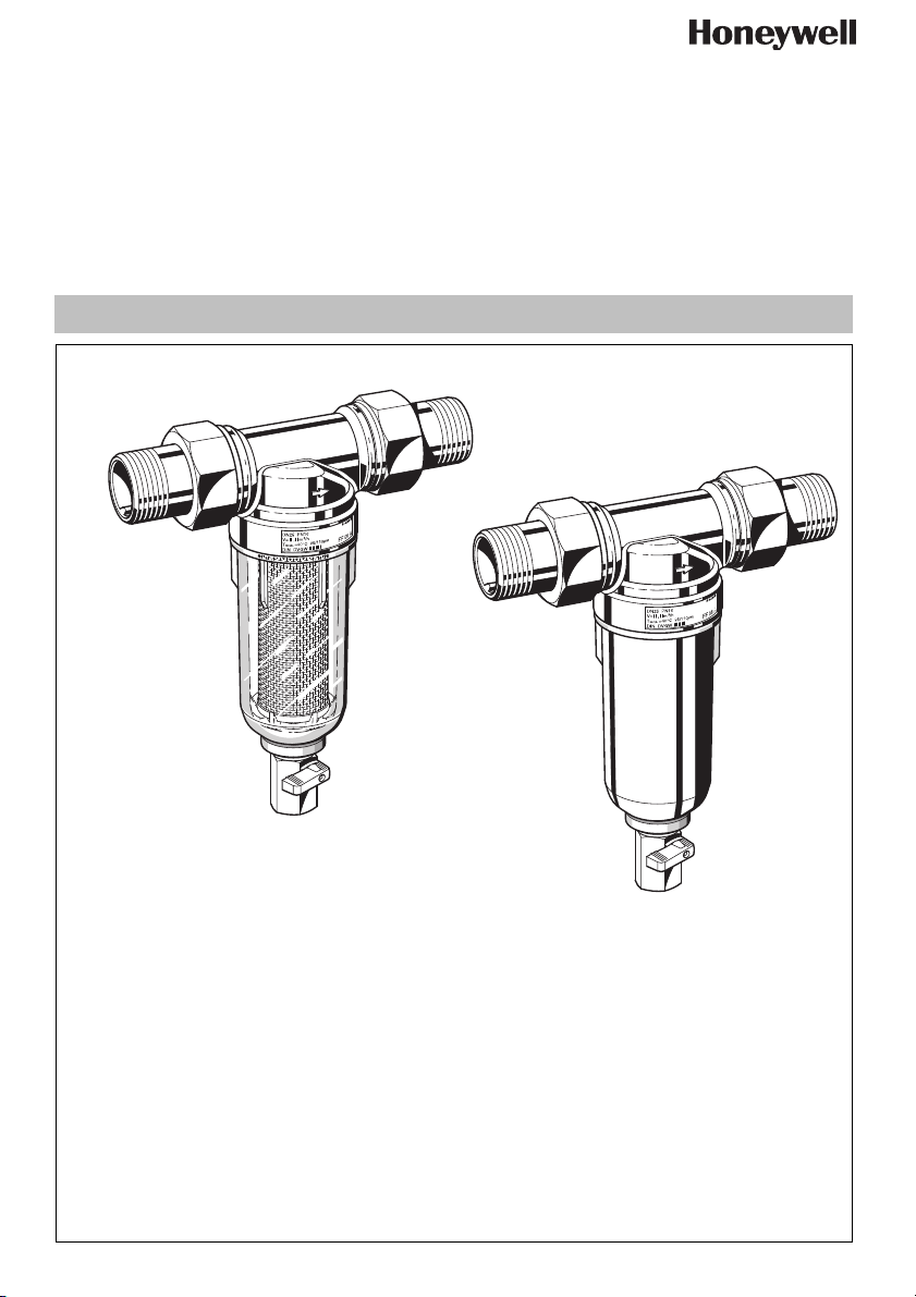
MiniPlus FF06 / FF06-AAM
Einbauanleitung • Installation instruction • Notice de montage • Installatiehandleiding
Istruzioni di montaggio • Instrucciones de montaje • ПАСПОРТ
Инструкция по монтажу
Anleitung zum späteren Gebrauch aufbewahren!
Keep instructions for later use!
Conserver la notice pour usage ultérieur!
Handleiding bewaren voor later gebruik!
Conservare le istruzioni per uso successivo!
Guardar estas Instrucciones para su uso futuro!
Сохранить инструкцию для последующего
пользования!
EB-FF06-FF06AAM Rev.A
Feinfilter
Fine filter
Filtre fin
Fijnfilter
Filtro a maglia fine
Filtro fino
Фильтр тонкой очистки для
питьевой воды
Page 2
D
1. Sicherheitshinweise
1. Beachten Sie die Einbauanleitung.
2. Benutzen Sie das Gerät
• bestimmungsgemäß
• in einwandfreiem Zustand
• sicherheits- und gefahrenbewusst.
3. Beachten Sie, dass das Gerät ausschließlich für den in
dieser Einbauanleitung genannten Verwendungsbereich
bestimmt ist. Eine andere oder darüber hinausgehende
Benutzung gilt als nicht bestimmungsgemäß.
4. Beachten Sie, dass alle Montage-, Inbetriebnahme,
Wartungs- und Justagearbeiten nur durch autorisierte
Fachkräfte ausgeführt werden dürfen.
5. Lassen Sie Störungen, welche die Sicherheit beeinträchtigen können, sofort beseitigen.
2. Funktionsbeschreibung
Der Feinfilter besteht aus einem Gehäuse und einem
ausspülbaren Feinfiltereinsatz.
Bei Normalbetrieb wird der Filtereinsatz von außen durchströmt und gefiltertes Wasser zum Ausgang des Gehäuses
geleitet. Zur Ausspülung wird der Kugelhahn geöffnet. Die
Schmutzpartikel werden mit dem durch den Kugelhahn
austretenden Wasserstrom abgeleitet. Auch während des
Ausspülvorgangs kann gefiltertes Wasser entnommen
werden.
3. Verwendung
Medium Wasser
Das Gerät wurde für den Einsatz im Trinkwasser entwickelt.
Die Verwendung in Prozesswässern ist im Einzelfall zu prüfen.
4. Technische Daten
Einbaulage waagrecht, mit Filtertasse nach unten
Betriebsdruck FF06-AA, FF06EA max. 16,0 bar
BetriebstemperaturFF06-AA, FF06EA max. 40 °C
Anschlussgröße
FF06-AAM max. 25,0 bar
FF06-AAM max. 70 °C
1
/2" , 3/4", 1", 11/4"
5. Lieferumfang
Der Feinfilter besteht aus:
• Gehäuse mit Innen- und Außengewinde
• Verschraubungen (nur Variante AA)
• Feinfilter in Klarsicht-Filtertasse
• Kugelventil
• Doppelringschlüssel für Filtertasse
6. Varianten
FF06-...AA = Mit Klarsichtfiltertasse, Gewindetülle,
FF06-...EA = Mit Klarsichtfiltertasse, ohne Anschlussver-
FF06-...AAM = Mit Messingfiltertasse, Gewindetülle,
Anschlussgröße
MU1H-1115GE23 R0609 2 Honeywell GmbH
untere/obere Durchlassweite 105/135 µm
schraubungen, untere/obere Durchlassweite
105/135 µm
untere/obere Durchlassweite 105/135 µm
7. Montage
7.1 Einbauhinweise
• Einbau in waagrechte Rohrleitung mit Filtertasse nach
unten
o In dieser Einbaulage ist eine optimale Funktion gewähr-
leistet
• Vor und nach dem Filter Absperrventile vorsehen
• Auf gute Zugänglichkeit achten
o Verschmutzungsgrad bei Klarsicht-Filtertasse gut
beobachtbar
o Vereinfacht Wartung und Inspektion
• Der Einbauort muss frostsicher sein
• Unmittelbar nach dem Wasserzähler einbauen
o Entsprechend DIN 1988, Teil 2
7.2 Montageanleitung
Wir empfehlen einen Rückflussverhinderer (siehe
Zubehör) vor dem Filter einzubauen
Bei Montage des Rückflussverhinderers Durchflussrichtung beachten.
Bei Löttüllen-Anschluss Tüllen nicht zusammen mit
dem Feinfilter löten. Hohe Temperaturen zerstören
funktionswichtige Innenteile!
1. Rohrleitung gut durchspülen
2. Filter einbauen
o Durchflussrichtung beachten
o spannungs- und biegemomentfrei einbauen
7.3 Ablauf Ausspülwasser
Das Ausspülwasser muss so zum Ablaufkanal geführt
werden, dass kein Rückstau entstehen kann.
1. Ablauf in einen Ablauftrichter
2. Ablauf frei in vorhandenen Bodenablauf
Filter-Größe Ausspülmenge* C (mm)
1/2" - 1 1/4“ 25 Liter 20
*bei 4 bar Eingangsdruck und 15 Sekunden Ausspüldauer
8. Instandhaltung
Wir empfehlen einen Wartungsvertrag mit einem
Installationsunternehmen abzuschließen
Entsprechend DIN 1988, Teil 8 sind folgende Maßnahmen
durchzuführen:
8.1 Inspektion
8.1.1 Filter ausspülen
Intervall: min. alle 2 Monate (abhängig von den örtlichen Bedingungen)
• Eine Nichtbeachtung kann zu Filterverstopfung
führen. Druckabfall und sinkender Wasserdurchfluss sind die Folge
• Die Siebe des Filters sind aus nichtrostendem
Stahl. Roter Belag infolge von Rost aus den Rohrleitungen hat keinen Einfluss auf Funktion und
Filterwirkung
Durchführung durch ein Installationsunternehmen
oder den Betreiber.
Page 3
D
Während des Ausspülens kann gefiltertes Wasser
entnommen werden
Bei offenen Ablauf in einen Behälter geeigneten
Behälter unter Kugelhahn stellen.
1. Kugelhahn am Drehknopf öffnen
o Drehknopf muss senkrecht stehen
2. Kugelhahn nach ca. 15 s wieder schließen
Bei stark verschmutzten Sieb kann die Dauer des
Rückspülens länger sein (Wechsel Sieb siehe
Wartung)
8.2 Wartung
8.2.1 Sieb wechseln
1. Absperrarmatur eingangsseitig schließen
2. Ausgangsseite druckentlasten (z.B. durch Wasserzapfen)
3. Absperrarmatur ausgangsseitig schließen
4. Filtertasse abschrauben
o Doppelringschlüssel ZR06F verwenden
5. Sieb austauschen
6. O-Ring auf Siebtasse stecken
7. Filtertasse handfest (ohne Werkzeug) einschrauben
8. Absperrarmatur eingangsseitig langsam öffnen
9. Absperrarmatur ausgangsseitig langsam öffnen
8.3 Reinigung
Vorsicht !
Zum Reinigen der Kunststoffteile keine lösungsmittel-
und/oder alkoholhaltigen Reinigungsmittel benutzen,
da diese zu Wasserschäden führen können!
Bei Bedarf können die Filtertasse und das Sieb gereinigt
werden.
Intervall: alle 6 Monate (abhängig von den örtlichen
Bedingungen)
Durchführung durch ein Installationsunternehmen.
Es dürfen keine Reinigungsmittel in die Umwelt oder
Kanalisation gelangen!
1. Absperrarmatur eingangsseitig schließen
2. Ausgangsseite druckentlasten (z.B. durch Wasserzapfen)
3. Absperrarmatur ausgangsseitig schließen
4. Filtertasse abschrauben
o Doppelringschlüssel ZR06F verwenden
5. Sieb herausnehmen, reinigen und wieder einstecken
6. O-Ring auf Siebtasse stecken
7. Filtertasse handfest (ohne Werkzeug) einschrauben
8. Absperrarmatur eingangsseitig langsam öffnen
9. Absperrarmatur ausgangsseitig langsam öffnen
9. Entsorgung
• Gehäuse aus Pressmessing, entzinkungsbeständig
• Verschraubungen aus Messing
• Feinfilter aus nichtrostendem Stahl
• Filtertasse aus stoßfestem, glasklarem Kunststoff oder
Messing
Die örtlichen Vorschriften zur ordnungsgemäßen
Abfallverwertung bzw. Beseitigung beachten!
10. Störungen / Fehlersuche
Störung Ursache Behebung
Kein oder zu wenig Wasserdruck Absperrarmaturen vor oder hinter dem
Filter nicht ganz geöffnet
Filtersieb verschmutzt Siebeinsatz reinigen oder ersetzen
Nicht in Durchflussrichtung montiert Filter in Durchflussrichtung montieren
Absperrarmaturen ganz öffnen
11. Ersatzteile 12. Zubehör
Nr.Bezeichnung Artikel-Nummer
1 Klarsicht-Filtertasse
komplett mit Sieb
und Stützkörper
2 O-Ring-Satz für
Stützkörper (10 Stück)
3 Ersatzsieb
1
/2" KF06-1/2A
3
/4" - 11/4"KF06-1A
1
/2" 0903127
3
/4" - 11/4" 0903128
1
/2" AS06-1/2A
3
/4" - 11/4" AS06-1A
4 O-Ring Satz
für Filtertasse
(10 Stück)
1
/2" 0901246
3
/4" - 11/4" 0901499
5 Doppelringschlüssel
zum Lösen der
Filtertasse (o. Abb.)
1
/2" - 11/4"ZR06F
Ersatzteile, Zubehöre können separat bestellt werden.
Honeywell GmbH 3 MU1H-1115GE23 R0609
RV277 Vorschalt-Rückflussverhinderer
Erhältlich in den Anschlussgrößen R
VST06 Anschluss-Set
Mit Gewindetülle oder Löttülle
A = Gewindetülle; B = Löttülle
1
/2" - 2"
Page 4
GB
1. Safety Guidelines
1. Follow the installation instructions.
2. Use the appliance
• according to its intended use
• in good condition
• with due regard to safety and risk of danger.
3. Note that the appliance is exclusively for use in the applications detailed in these installation instructions. Any other
use will not be considered to comply with requirements
and would invalidate the warranty.
4. Please take note that any assembly, commissioning,
servicing and adjustment work may only be carried out by
authorized persons.
5. Immediately rectify any malfunctions which may influence
safety.
2. Functional description
The MiniPlus fine filter is composed of a body and a rinsable
fine filter insert.
During normal operation, water flows through the filter mesh
to the body outlet. To rinse the filter, the ball valve is opened
which discharges the dirt particles. A continous supply of
filtered water is available also during the rinse cycle.
3. Application
Medium Water
The filter is constructed for drinking water installations. In
case of a process water application the filter has to be proven
individually.
4. Technical data
Installation position Horizontal with filter bowl downwards
Operating pressure FF06-AA, FF06EA max. 16.0 bar
Operating temperature FF06-AA, FF06EA max. 40 °C
Connection size
FF06-AAM max. 25.0 bar
FF06-AAM max. 70 °C
1
/2" , 3/4", 1", 11/4"
5. Scope of delivery
The fine filter comprises:
• Housing with female and male threads
• Threaded connections (version AA)
• Fine filter in clear filter bowl
• Ball valve
• Double wring wrench
6. Options
FF06-...AA = with clear filter bowl, threaded male connec-
FF06-...EA = with clear filter bowl, without connections,
FF06-...AAM = with brass filter bowl, threaded male connec-
tions, filter mesh size 100 µm
filter mesh size 100 µm
tions, filter mesh size 100 µm
7. Assembly
7.1 Installations Guidelines
• Install in horizontal pipework with filter bowl downwards
o This position ensures optimum filter efficiency
• Install shutoff valves
• Ensure good access
o Degree of contamination can be seen with clear filter
bowl
o Simplifies maintenance and inspection
• The installation location should be protected against frost
• Fit immediately after water meter
o Corresponds to DIN 1988, Part 2
7.2 Assembly instructions
We recommend to install an inlet check valve (accessories)
Observe the flow direction when mounting the backflow
preventer.
When connecting the solder sockets, do not solder the
sockets together with the filter. High temperatures
destroy internal parts which are important to the function!
1. Thoroughly flush pipework
2. Install filter
o Note flow direction
o Install without tension or bending stresses
7.3 Drain for rinse water
The rinse water must be piped to the drain in such a way
that no back pressure can oc-cur
1. Discharge into drain connector
2. Discharge into floor drain
Filter size Reverse rinsing quantity*C (mm)
1/2" - 1 1/4“ 25 litres 20
*at 4,0 bar inlet pressure and a rinse duration of 15 seconds
8. Maintenance
We recommend a planned maintenance contract with
an installation company
In accordance with DIN 1988, part 8, the following measures
must be taken:
8.1 Inspection
8.1.1 Rinse filter
Frequency: at least every 2 month (depending on local
operating conditions
• Non-compliance can lead to the filter becoming
blocked This results in a drop in pressure and
decreasing water flow
• The filter meshes are made of stainless steel. A red
coating as a consequence of rust from the pipelines
has no influence on function or the way the filter
works
To be carried out by an installation company or the
operator.
Filtered water can be drawn during rinsing.
MU1H-1115GE23 R0609 4 Honeywell GmbH
Page 5
GB
If rinsing is into a container, then a suitable container
must first be put underneath.
1. Open the ball valve by turning the rinse knob
o Rinse knob must be vertical
2. Close the ball valve after approximately 15 seconds
A longer reverse rinse period may be necessary if the
filter is very dirty (Replace filter mesh see Servicing)
8.2 Servicing
8.2.1 Replace filter mesh
1. Close shutoff valve on inlet
2. Release pressure on outlet side (e.g. through water tap)
3. Close shutoff valve on outlet
4. Unscrew filter bowl
o Use double ring wrench ZR06F
5. Replace filter mesh
6. Place O-ring onto filter bowl
7. Screw in filter bowl hand-tight (without tools)
8. Slowly open shutoff valve on inlet
9. Slowly open shutoff valve on outlet
8.3 Cleaning
Caution !
Do not use any cleaning agents containing solvents
and/or alcohol to clean the plastic parts!
If necessary, the filter bowl and the filter can be cleaned.
Frequency: every 6 month (depending on local operating conditions)
To be carried out by an installation company
Detergents must not be allowed to enter the environment or the sewerage system!
1. Close shutoff valve on inlet
2. Release pressure on outlet side (e.g. through water tap)
3. Close shutoff valve on outlet
4. Unscrew filter bowl
o Use double ring wrench ZR06F
5. Remove filter, clean and reinsert
6. Place O-ring onto filter bowl
7. Screw in filter bowl hand-tight (without tools)
8. Slowly open shutoff valve on inlet
9. Slowly open shutoff valve on outlet
9. Disposal
• Body of dezincification resistant pressed brass
• Brass threaded connections
• Stainless steel fine filter
• Red-bronze or shock-resistant, clear transparent synthetic
material filter bowl
Observe the local requirements regarding correct waste
recycling/disposal!
10. Troubleshooting
Problem Cause Remedy
Too little or no water pressure Shutoff valves upstream or downstream
Open the shutoff valves fully
from filter not fully open
Filter mesh dirty Clean or replace filter
Not fitted in flow direction Fit filter in flow direction
11. Spare Parts 12. Accessories
No. Description Part No.
1 Clear filter bowl
complete with sieve
and mesh carrier
2 O-ring set for
mesh carrier
1
/2" KF06-1/2A
3
/4" - 11/4" KF06-1A
1
/2" 0903127
3
/4" - 11/4" 0903128
(pack of 10)
3 Replacement
sieve
1
/2" AS06-1/2A
3
/4" - 11/4" AS06-1A
4 O-ring set
for filter bowl
(pack of 10)
1
/2" 0901246
3
/4" - 11/4" 0901499
5 Doppelringschlüssel
zum Lösen der
Filtertasse (o. Abb.)
1
/2" - 11/4"ZR06F
Spare parts can be purchased separately only in addition.
RV277 Inlet check valve
Available in sizes R
VST06 Connection set
Connection set
A = Threaded male connection;
B = Solder union connection
1
/2" - 2"
Honeywell GmbH 5 MU1H-1115GE23 R0609
Page 6
F
1. Consignes de sécurité
1. Suivre les indications de la notice de montage.
2. En ce qui concerne l'utilisation de l'appareil
• Utiliser cet appareil conformément aux données du
constructeur
• Maintenir l'appareil en parfait état
• Respectez les consignes de sécurité
3. Il faut noter que cet équipement ne peut être mis en oeuvre
que pour les conditions d'utilisation mentionnées dans
cette notice. Toute autre utilisation, ou le non respect des
conditions normales d'utilisation, serait considérée comme
non conforme.
4. Observer que tous les travaux de montage, de mise en
service, d'entretien et de réglage ne pourront être effectués que par des spécialistes autorisés.
5. Prendre des mesures immédiates en cas d'anomalies
mettant en cause la sécurité.
2. Description fonctionnelle
Le filtre fin se compose d’une cuve et d’une cartouche filtrante
fine pouvant être rincée.
Lors du fonctionnement normal, la cartouche filtrante est
traversée de l’extérieur vers l’intérieur et l’eau filtrée est
amenée jusqu’à la sortie de la cuve. Le robinet est ouvert
pour le rinçage. Les particules de saleté sont alors évacuées
avec le flux d’eau s’écoulant du robinet. De l’eau filtrée peut
également être prélevée pendant le rinçage.
3. Mise en oeuvre
Fluide Eau
L'appareil a été développé pour l'utilisation dans l'eau
potable. L'utilisation dans les eaux de procédé est à contrôler
de cas en cas.
4. Caractéristiques
Position de montage À l’horizontale, tasse filtrante vers le bas
Pression de service FF06-AA, FF06EA max. 16,0 bars
Température de
fonctionnement
Dimensions de
raccordement
FF06-AAM max. 25,0 bars
FF06-AA, FF06EA max. 40 C
FF06-AAM max. 70 C
1
/2" ,3/4", 1", 11/4"
5. Contenu de la livraison
Le filtre fin comprend :
• Cuve avec filets mâle et femelle
• Raccords vissés (modèle AA uniquement)
• Microfiltre dans la cuve de filtre transparente
• Vanne sphérique
• Clé polygonale double pour tasse filtrante
6. Variantes
FF06-...AA = Avec tasse filtrante transparente, douille
FF06-...EA = Avec tasse filtrante transparente, sans
FF06-...AAM = Avec tasse filtrante en laiton, douille filetée,
filetée, largeur min./max. des mailles 105/
135µm
raccords vissés, largeur min./max. des
mailles 105/135µm
largeur min./max. des mailles 105/135µm
7. Montage
7.1 Dispositions à prendre
• Installer dans la tuyauterie horizontale avec le bocal du
filtre vers le bas
o Cette position assure une efficacité de filtrage optimale
• Installer des vannes d'isolement avant et après le filtre
• Veiller à un accès facile
o Le degré de contamination est visible sur la cuve trans-
parente du filtre.
o Simplifie la maintenance et l'inspection
• Le lieu de montage doit être à l'abri du gel.
• Monter directement après le compteur d'eau
o conformément à la DIN 1988, partie 2
7.2 Instructions de montage
Nous recommandons de monter un clapet anti-retour
(voir Accessoires) avant le filtre.
Lors du montage du clapet d'aspiration, respecter le
sens du flux.
Dans le cas de raccordement avec douilles brasées, ne
pas braser les douilles avec le filtre fin. Les températures élevées abîment les pièces internes fonctionnelles !
1. Bien rincer la conduite
2. Installer le filtre
o Vérifier le sens de passage du fluide
o Vérifier l'absence de contraintes anormales en traction
et en flexion
7.3 Ecoulement de l’eau de rinçage
L’eau de rinçage doit être amenée vers le canal
d’évacuation de sorte qu’aucun reflux ne soit possible.
1. Ecoulement dans un entonnoir à trop-plein
2. Ecoulement libre dans l’évacuation présente au fond de la
cuve
Taille du filtre Quantité de rinçage* C (mm)
1/2" - 1 1/4“ 25 litres 20
*pour une pression d’entrée de 4 bars et un rinçage de 15
secondes
8. Maintenance
Nous recommandons de conclure un contrat d'entretien
avec un installateur
Les opérations suivantes seront effectuées selon les recommandations de la norme DIN 1988, section 8.
MU1H-1115GE23 R0609 6 Honeywell GmbH
Page 7

F
8.1 Inspection
8.1.1 Rinçage du filtre
Intervalle : au moins tous les 2 mois (en fonction des
conditions rencontrées sur le lieu d’utilisation)
• le non-respect peut provoquer un engorgement du
filtre. Une chute de pression et une diminution du
débit de l'eau en sont les conséquences.
• Les tamis du filtre sont en inox. Une couche rouge de
rouille provenant des conduites n'a pas d'influence
sur la fonction et l'effet du filtre
Réalisation par une entreprise d'installation ou l'exploitant.
De l’eau filtrée peut être prélevée pendant le rinçage.
8.3 Nettoyage
Attention !
Pour le nettoyage des pièces en matière synthétique,
n'utilisez pas de produits solvants ni contenant de
l'alcool, car cela pourrait provoquer des dégâts d'eau!
Il est possible de nettoyer le pot de tamisage et le filtre de
remplacement en cas de besoin.
Intervalle : tous les 6 mois (en fonction des conditions
locales)
Opération effectuée par un professionnel
Ne pas rejeter de produit détergent dans l'environnement ou dans les canalisations!
1. Fermer la robinet de fermeture du côté de l'entrée
2. Dépressuriser le côté sortie (ouverture du robinet de
Placer un récipient adapté sous le robinet lorsque
l’évacuation est ouverte.
1. Ouvrir le robinet au moyen du bouton tournant.
o Le bouton doit se trouver à la verticale.
2. Refermer le robinet après env. 15 s.
Le rinçage peut être plus long lorsque le tamis est fortement encrassé. (Remplacement du tamis : voir « Entretien »)
8.2 Maintenance
8.2.1 Remplacement du tamis
1. Fermer la robinet de fermeture du côté de l'entrée
2. Dépressuriser le côté sortie (ouverture du robinet de
purge, etc.)
3. Fermer la vanne d'isolement côté sortie
4. Dévisser la cuve du filtre
o Utiliser la clé polygonale double ZR06F
5. Remplacer le tamis.
6. Enfoncer l'anneau torique sur le pot de tamisage
7. Vissez à fond la cuve du filtre (sans outil)
purge, etc.)
3. Fermer la vanne d'isolement côté sortie
4. Dévisser la cuve du filtre
o Utiliser la clé polygonale double ZR06F
5. Retirer le filtre de remplacement, le nettoyer et le replace
6. Enfoncer l'anneau torique sur le pot de tamisage
7. Vissez à fond la cuve du filtre (sans outil)
8. Ouvrir lentement la vanne d'isolement côté entrée
9. Ouvrir lentement la vanne d'isolement côté sortie
9. Matériel en fin de vie
• Cuve en laiton travaillé à chaud, résistant à la dégalvanisation
• Raccords vissés en laiton
• Microfiltre en inox
• Tasse filtrante en plastique transparent résistant aux
coups ou en laiton
Se conformer à la réglementation pour l'élimination des
équipements industriels en fin de vie vers les filières de
traitement autorisées!
8. Ouvrir lentement la vanne d'isolement côté entrée
9. Ouvrir lentement la vanne d'isolement côté sortie
10. Défaut / recherche de panne
Panne Cause Remède
Pression d'eau insuffisante ou nulle Appareils de sectionnement devant ou
derrière le filtre fin pas totalement ouvert
Tamis de filtre sale Nettoyer le tamis de remplacement
Pas monté dans le sens du débit Monter le filtre dans le sens d’écoulement
11. Pièces de rechange
N° Désignation Numéro
d'article
1 Tasse filtrante transparente
complète, avec tamis
et support
2 Jeu de joints toriques pour
support (10 pièces)
3 Tamis de rechange
4 Jeu de joints toriques
pour tasse filtrante
(10 pièces)
1
/2" KF06-1/2A
3
/4" - 11/4"KF06-1A
1
/2" 0903127
3
/4" - 11/4" 0903128
1
/2" AS06-1/2A
3
/4" - 11/4" AS06-1A
1
/2" 0901246
3
/4" - 11/4" 0901499
5 Clé polygonale double
pour le desserrage de
la tasse filtrante (non ill.)
Les pièces de rechange et accessoires peuvent être
commandés séparément.
12. Accessoires
RV277 Clapet antiretour amont
In toutes diamètres de raccordement
VST06 Jeu de raccords
à visser ou à souder
A = raccord à visser
B = raccord à souder
Honeywell GmbH 7 MU1H-1115GE23 R0609
Ouvrir complètement les vannes d'isolement
1
/2" - 11/4" ZR06F
Page 8

NL
1. Veiligheidsvoorschriften
1. Lees de installatiehandleiding goed door.
2. Gebruik het apparaat
• waarvoor het is bestemd
• in goede toestand
• met aandacht voor de veiligheid en mogelijke gevaren
3. Let op dat het apparaat uitsluitend bestemd is voor het
toepassingsgebied dat in de installatiehandleiding wordt
aangegeven. Elk ander gebruik geldt als niet in overeenstemming met het doel waarvoor het is bestemd, waardoor
de garantie vervalt.
4. Houd er rekening mee dat alle montage-, ingebruikname-,
onderhouds- en aanpassingswerkzaamheden alleen
mogen worden uitgevoerd door gekwalificeerde
vakmensen.
5. Laat storingen die de veiligheid kunnen aantasten direct
verhelpen.
2. Functiebeschrijving
Het fijnfilter bestaat uit een huis en een uitspoelbaar filterelement.
Bij normaal bedrijf wordt het filterelement van buiten doorstroomd en gefilterd water naar de uitgang van het huis
geleid. Voor de uitspoeling wordt de kogelkraan geopend. De
vuildeeltjes worden met het door de kogelkraan uitstromende
water afgevoerd. Ook tijdens het uitspoelen kan er gefilterd
water worden afgetapt.
3. Gebruik
Medium Water
Het apparaat werd ontwikkeld voor de inzet in het drinkwater.
Het gebruik in proceswater moet van geval tot geval gecontroleerd worden.
4. Technische gegevens
Inbouwpositie horizontaal, met filterbeker naar beneden
Bedrijfsdruk FF06-AA, FF06EA max. 16,0 bar
BedrijfstemperatuurFF06-AA, FF06EA max. 40 C
Aansluitmaat
FF06-AAM max. 25,0 bar
FF06-AAM max. 70 C
1
/2" ,3/4", 1", 11/4"
5. Leveringsomvang
Het fijnfilter bestaat uit:
• Huis met inwendige en uitwendige schroefdraad
• Schroefverbindingen (alleen variant AA)
• Fijnfilter in transparante filterbeker
• Kogelklep
• Dubbele ringsleutel voor filterbeker
6. Modellen
FF06-...AA = Met transparante filterbeker, schroefdraad-
mondstuk, onderste/bovenste doorlaatwijdte
105/135µm
FF06-...EA = Met transparante filterbeker, zonder aanslu-
itschroefverbindingen, onderste/bovenste
doorlaatwijdte 105/135µm
FF06-...AAM = Met messing filterbeker, schroefdraadmond-
stuk, onderste/bovenste doorlaatwijdte 105/
135µm
7. Montage
7.1 Montage-instructies
• Te installeren in horizontale leiding met de zeefhouder
naar beneden gericht
o In deze positie is de werking van de filter optimaal
• Monteer afsluitkranen voor en na de filter
• Zorg voor een goede toegankelijkheid
o Dankzij de transparante zeefhouder kan de mate van
verontreiniging worden vastgesteld
o Vergemakkelijkt onderhoud en inspectie
• De montageplek moet vorstvrij zijn
• Onmiddellijk na de watermeter inbouwen
o Overeenkomstig DIN 1988, deel 2
7.2 Montagehandleiding
Wij raden aan om een terugstroomverhinderaar (zie
toebehoren) in te bouwen voor het filter.
Bij montage van de terugstroomverhinderaar rekening
houden met de doorstroomrichting.
Bij aansluiting soldeermoffen moffen niet samen met
fijnfilter solderen. Hoge temperaturen vernielen voor de
functie belangrijke inwendige onderdelen!
6. Buisleiding goed doorspoelen.
7. Filter installeren
o Let op de doorstroomrichting
o Spannings- en buigmomentvrij installeren
7.3 Afvoer uitspoelwater
Het uitspoelwater moet zo naar het afvoerkanaal
worden geleid, dat er geen opstuwing kan ontstaan.
1. Afvoer naar een afvoertrechter
2. Afvoer vrij naar bestaand afvoerputje
Filtergrootte Uitspoelhoeveelheid* C (mm)
1/2" - 1 1/4“ 25 liter 20
*bij 4 bar ingangsdruk en 15 seconden uitspoelduur
8. Onderhoud
Wij raden u aan een onderhoudscontact met een instal-
latiebedrijf af te sluiten!
Volgens DIN 1988, deel 8 moet het volgende worden uitgevoerd:
MU1H-1115GE23 R0609 8 Honeywell GmbH
Page 9

NL
8.1 Inspectie
8.1.1 Filter uitspoelen
Interval: min. om de 2 maanden (afhankelijk van de
plaatselijke voorwaarden)
• Als dit niet gebeurt, dan kan het filter verstopt raken.
Drukval en dalende waterdoorstroming zijn het
gevolg
• De zeven van het filter zijn van roestvrij staal. Rode
bedekking als gevolg van roest uit de buisleidingen
heeft geen invloed op functie en filterwerking
Uitvoering door een installatiebedrijf of de exploitant.
Tijdens het uitspoelen kan er gefilterd water worden
afgetapt.
Bij open afvoer naar een reservoir een geschikt reservoir onder de kogelkraan zetten.
1. Kogelkraan openen aan de draaiknop.
o Draaiknop moet verticaal staan.
2. Kogelkraan na ca. 15 s weer sluiten.
Bij sterk vervuilde zeef kan de duur van het terugspoelen langer zijn (vervanging zeef zie Onderhoud).
8.2 Onderhoud
8.2.1 Zeef vervangen
1. Afsluitstuk ingangskant sluiten
2. Uitgangskant drukontlasten (b.v. door watertap)
3. Afsluitstuk uitgangskant sluiten.
4. Zeefhouder losdraaien
o Dubbelringsleutel ZR06F gebruiken
5. Zeef vervangen
6. O-ring op de zeefbeker steken
7. Filterbeker handvast (zonder gereedschap) erin
schroeven.
8.3 Reiniging
Voorzichtigheid !
Om de kunststof delen te reinigen geen oplosmiddelen/of alcoholhoudende reinigingsmiddelen gebruiken,
aangezien deze waterschade kunnen veroorzaken!
Indien nodig kunnen de filterbeker en de zeef gereinigd
worden.
Interval: om de 6 maanden (afhankelijk van de plaatselijke voorwaarden)
Uit te voeren door een installatiebedrijf
Reinigingsmiddelen mogen niet in het milieu of de riolering komen!
1. Afsluitstuk ingangskant sluiten
2. Uitgangskant drukontlasten (b.v. door watertap)
3. Afsluitstuk uitgangskant sluiten.
4. Zeefhouder losdraaien
o Dubbelringsleutel ZR06F gebruiken
5. Zeef eruit nemen, reinigen en weer erin steken
6. O-ring op de zeefbeker steken
7. Filterbeker handvast (zonder gereedschap) erin
schroeven.
8. Afsluitstuk ingangskant langzaam openen.
9. Afsluiter aan de uitgang traag openen
9. Recyclage
• Huis van warmgeperst messing, ontzinkingsbestendig
• Schroefverbindingen van messing
• Fijnfilter van roestvrij staal
• Filterbeker van schokbestendig, glashelder kunststof of
messing
De plaatselijke voorschriften voor de juiste afvalrecycling resp. -afvoer moeten worden opgevolgd!
8. Afsluitstuk ingangskant langzaam openen.
9. Afsluiter aan de uitgang traag openen
10. Storing / Opzoeken en verhelpen van fouten
Storing Oorzaak Oplossing
Geen of te weinig waterdruk Afsluitkleppen voor of achter het filter niet
helemaal geopend
Filterzeef vervuild Vervangingszeef reinigen
Niet gemonteerd in doorstroomrichting Filter in stroomrichting plaatsen
11. Reserveonderdelen
+Nr.Benaming Artikelnummer
1 Transparante filterbeker
compleet met zeef
en steunelement
2 O-ringset voor
steunelement (10 stuks)
3 Reservezeef
4 O-ringset
voor filterbeker
(10 stuks)
1
/2" KF06-1/2A
3
/4" - 11/4"KF06-1A
1
/2" 0903127
3
/4" - 11/4" 0903128
1
/2" AS06-1/2A
3
/4" - 11/4" AS06-1A
1
/2" 0901246
3
/4" - 11/4" 0901499
5 Dubbelringsleutel
om de filterbeker
los te draaien (niet afgeb.)
Reserveonderdelen, accessoires kunnen apart besteld
worden.
12. Accesoires
RV277 Ingangskeerklep
In alle aansluitmaten
VST06 Aansluitset
Afsluitkleppen volledig openen
Aansluitset
A = buitendraadaansluiting;
B = soldeeraansluiting
1
/2" - 11/4" ZR06F
Honeywell GmbH 9 MU1H-1115GE23 R0609
Page 10

I
1. Avvertenze di sicurezza
1. Rispettare le istruzioni di montaggio.
2. Utilizzare l'apparecchio
• secondo la destinazione d'uso
• in uno stato perfetto
• in modo sicuro e consapevoli dei pericoli connessi
3. Si prega di considerare che l'apparecchio è realizzato
esclusivamente per il settore d'impiego riportato nelle
presenti istruzioni d'uso. Un uso differente o diverso da
quello previsto è da considerarsi improprio.
4. Osservare che tutti i lavori di montaggio, di messa in
funzione, di manutenzione e di regolazione devono essere
eseguiti soltanto da tecnici specializzati e autorizzati.
5. I guasti che potrebbero compromettere la sicurezza
devono essere risolti immediatamente.
2. Descrizione del funzionamento
Il filtro a maglia fine è costituito da una scatola e da una
cartuccia lavabile.
In condizioni di funzionamento normali, la cartuccia viene
attraversata dall'esterno e l'acqua filtrata viene trasportata
verso l'uscita della scatola. Per il lavaggio è necessario aprire
il rubinetto a sfera. Le particelle di sporco vengono eliminate
dalla corrente d'acqua che fuoriesce dal rubinetto a sfera.
L'acqua filtrata può essere prelevata anche durante la procedura di lavaggio.
3. Uso
Mezzo acqua
L'apparecchio è stato progettato per l'impiego con acqua
potabile. L'impiego nelle acque di processo va verificato nel
caso singolo.
4. Dati tecnici
Posizione di installazione
Pressione di esercizioFF06-AA, FF06EA max. 16,0 bar
Temperatura di esercizio
Dimensioni attacchi
orizzontale, con tazza del filtro rivolta
verso il basso
FF06-AAM max. 25,0 bar
FF06-AA, FF06EA max. 40 C
FF06-AAM max. 70 C
1
/2" ,3/4", 1", 11/4"
5. Fornitura
Il filtro a maglia fine si compone di:
• scatola con filetto interno e filetto esterno
• collegamenti a vite (solo variante AA)
• microfiltro in tazza del filtro trasparente
• valvola a sfera
• chiave poligonale doppia per tazza del filtro
6. Varianti
FF06-...AA = con tazza del filtro trasparente, bocchetta filet-
FF06-...EA = con tazza del filtro trasparente, senza collega-
FF06-...AAM = Con tazza del filtro in ottone, bocchetta filet-
MU1H-1115GE23 R0609 10 Honeywell GmbH
tata, passaggio inferiore/superiore 105/135µm
menti a vite, passaggio inferiore/superiore 105/
135µm
tata, passaggio inferiore/superiore 105/135µm
7. Montaggio
7.1 Istruzioni di installazione
• Montaggio in tubazione orizzontale con tazza del filtro
verso il basso
o In questa posizione di montaggio è garantito un funzion-
amento ottimale
• Prevedere rubinetti d'intercettazione a valle e a monte del
filtro
• Garantire una buona accessibilità
o Con tazza del filtro trasparente, il grado di intasamento
è benvisibile
o Facilita la manutenzione e l'ispezione
• Il punto di installazione dev'essere esente da congelamenti
• Montare subito dopo il contatore dell'acqua
o Conforme a DIN 1988, parte 2
7.2 Istruzioni di montaggio
Si consiglia l'installazione di una valvola antiritorno
(vedere accessori) a monte del filtro
Durante il montaggio del dispositivo antiritorno
rispettare la direzione del flusso.
In caso di raccordi a saldare, non saldare il cappuccio
insieme al filtro a maglia fine. Le alte temperature possono
distruggere parti interne importanti per il funzionamento!
1. Sciacquare bene la tubazione.
2. Montare il filtro
o Rispettare la direzione del flusso
o senza tensione e momento flettente
7.3 Scarico dell'acqua di lavaggio
L'acqua di lavaggio deve essere convogliata verso il
canale di scarico in modo che non possa verificarsi un
ristagno.
1. Scarico in un imbuto
2. Scarico libero nella colonna di scarico esistente
Grandezza filtro Quantità lavaggio* C (mm)
1/2" - 1 1/4“ 25 litri 20
*Con pressione d'ingresso di 4 bar e lavaggio di 15 secondi
8. Manutenzione
Consigliamo di stipulare un contratto di manutenzione
con un'azienda di installazione
In conformità alla norma DIN 1988, parte 8 è necessario
eseguire le seguenti operazioni:
8.1 Ispezione
8.1.1 Lavaggio del filtro
Intervallo: almeno ogni 2 mesi (a seconda delle condizioni
locali)
• L'inosservanza potrebbe provocare l'intasamento del
filtro, avendo come conseguenze una caduta di pressione e un flusso ridotto.
• I setacci del filtro sono di acciaio inossidabile. Il deposito rosso causato dalla ruggine, proveniente dalle
tubazioni, non influisce in alcun modo sul funzionamento e sull'effetto filtrante
Esecuzione tramite un'impresa di installazioni o il gestore.
Page 11

I
Durante il lavaggio è possibile il prelevamento di acqua
filtrata
In caso di scarico libero in un recipiente, posizionare un
recipientev adatto sotto al rubinetto a sfera.
1. Aprire il rubinetto a sfera ruotando la manopola
o La manopola deve trovarsi in posizione verticale
2. Dopo circa 15 s chiudere nuovamente il rubinetto a sfera
Con setaccio molto intasato, il lavaggio può anche
durare più a lungo (per la sostituzione del setaccio
vedere Manutenzione)
8.2 Manutenzione
8.2.1 Sostituzione del setaccio
1. Chiudere l'armatura di chiusura lato entrata
2. Depressurizzare il lato di uscita (per es. tramite il rubinetto
dell'acqua).
3. Chiudere il raccordo di blocco sul lato di uscita.
4. Svitare la tazza del filtro
o Utilizzare una chiave ad anello doppia ZR06F
5. Sostituire il setaccio
6. Mettere l'anello circolare sulla tazza a vaglio
7. Avvitare manualmente (senza attrezzi) la tazza del filtro
8. Aprire il raccordo di blocco sul lato di ingresso.
9. Aprire il raccordo di blocco sul lato di uscita.
8.3 Pulizia
Attenzione !
Per pulire le parti in plastica non utilizzare alcun detergente contenente solvente o alcol, poiché questi
potrebbero provocare danni all'acqua!
All'occorrenza è possibile pulire la tazza del filtro e il setaccio.
Frequenza: ogni 6 mesi (dipendente dalle condizioni
locali)
Esecuzione ad opera di un'azienda di installazione
Nell'ambiente o nella canalizzazione è necessario che
non venga scaricato alcun detergente!
1. Chiudere l'armatura di chiusura lato entrata
2. Depressurizzare il lato di uscita (per es. tramite il rubinetto
dell'acqua).
3. Chiudere il raccordo di blocco sul lato di uscita.
4. Svitare la tazza del filtro
o Utilizzare una chiave ad anello doppia ZR06F
5. Togliere il setaccio, pulirlo e inserirlo di nuovo
6. Mettere l'anello circolare sulla tazza a vaglio
7. Avvitare manualmente (senza attrezzi) la tazza del filtro
8. Aprire il raccordo di blocco sul lato di ingresso.
9. Aprire il raccordo di blocco sul lato di uscita.
9. Smaltimento
• Scatola in ottone stampato, resistente alla dezincatura
• Raccordi a vite in ottone
• Microfiltro di acciaio inossidabile
• Tazza del filtro in ottone o plastica trasparente antiurto
Rispettare le norme locali relative al riciclaggio o allo
smaltimento a regola d'arte di rifiuti!
10. Guasti / Ricerca guasti
Guasto Causa Risoluzione
La pressione dell'acqua è poca oppure
inesistente
Rubinetti d'intercettazione a monte o a
valle del filtro non completamente aperti
Aprire completamente i raccordi di blocco
Setaccio del filtro intasato Pulire il vaglio di riserva
Il filtro non è montato nella direzione del
Montare il filtro nella direzione del flusso
flusso
11. Pezzi di ricambio 12. Accessori
N. Denominazione N. art.
1 Tazza del filtro trasparente
completa di setaccio
e corpo di sostegno
2 Kit di O-ring per
corpo di sostegno (10 pezzi)
3 Setaccio di ricambio
1
/2" KF06-1/2A
3
/4" - 11/4" KF06-1A
1
/2" 0903127
3
/4" - 11/4" 0903128
1
/2" AS06-1/2A
3
/4" - 11/4" AS06-1A
4 Kit di O-ring
per tazza del filtro
(10 pezzi)
1
/2" 0901246
3
/4" - 11/4" 0901499
5 Chiave ad anello doppia
per allentare la
tazza del filtro (senza figura)
I ricambi e gli accessori possono essere ordinati sepa-
1
/2" - 11/4" ZR06F
ratamente.
RV277 Dispositivo anti-ritorno di mandata
Tutti dimensioni attacchi
VST06 Set di raccordi
Con raccordo filettato o saldato
A = raccordo filettato; B = raccordo saldato
Honeywell GmbH 11 MU1H-1115GE23 R0609
Page 12

ES
1. Indicaciones de seguridad
1. Siga las instrucciones de montaje.
2. Utilice el aparato
• conforme a lo previsto
• en estado correcto
• teniendo en cuenta los riesgos y la seguridad.
3. Tenga en cuenta que la válvula ha sido diseñada exclusivamente para las aplicaciones indicadas en estas
instrucciones de montaje. Una utilización distinta no se
considerará conforme a lo previsto.
4. Tenga en cuenta que los trabajos de montaje, de puesta
en funcionamiento, de mantenimiento y de ajuste sólo
deben efectuarlos técnicos especialistas autorizados.
5. Solucione de inmediato los fallos que puedan afectar a la
seguridad.
2. Descripión de funcionamiento
El filtro fino consta de una carcasa y de un cartucho de filtro
fino lavable.
En caso de funcionamiento normal, el agua atraviesa desde
fuera el cartucho de filtro y pasa filtrada hasta la salida de la
carcasa. Para el lavado se abre el grifo de bola. Las partículas de suciedad se eliminan con la corriente de agua que
sale del grifo de bola. También se puede extraer agua filtrada
durante el proceso de lavado.
3. Rango de aplicación
Medio Agua
El equipo se ha diseñado para ser utilizado con agua potable.
Su empleo en aguas de proceso deberá comprobarse en
cada caso en particular.
4. Datos técnicos
Posición de montaje horizontal, con vaso de filtro hacia abajo
Presión de servicio FF06-AA, FF06EA máx. 16,0 bar
Temperatura de trabajoFF06-AA, FF06EA máx. 40 °C
Tamaño de la conexión
FF06-AAM máx. 25,0 bar
FF06-AAM máx. 70 °C
1
/2" , 3/4", 1", 11/4"
5. Suministro
El filtro fino se compone por:
• Carcasa con rosca interior y exterior
• Uniones atornilladas (sólo en la variante AA)
• Filtro fino en vaso de filtro transparente
• Válvula esférica
• Llave de estrella de dos bocas para vaso de filtro
6. Suministro
FF06-...AA = Con vaso de filtro transparente, manguito
FF06-...EA = Con vaso de filtro transparente, sin uniones
FF06-...AAM = Con vaso de filtro de latón, manguito
MU1H-1115GE23 R0609 12 Honeywell GmbH
roscado, amplitud de paso inferior/superior
105/135 µm
atornilladas de conexión, amplitud de paso
inferior/superior 105/135 µm
roscado, amplitud de paso inferior/superior
105/135 µm
7. Montaje
7.1 Notas para el montaje
• Montaje en tubería horizontal con vaso de filtro hacia
abajo
o En esta posición de montaje se garantiza un funciona-
miento óptimo
• Prever antes y después del filtro válvulas de corte
• Observe que la accesibilidad sea buena
o El grado de suciedad se deja observar bien en el vaso
de filtro transparente
o Simplificación de mantenimiento e inspección
• El local de montaje debe estar protegido contra heladas
• Montar directamente después del contador de agua
o Según DIN 1988, parte 2
7.2 Instrucciones de montaje
Recomendamos montar una válvula antirretorno
(véase accesorios) antes del filtro
Cuando se monte la válvula antirretorno se debe
respetar la dirección de la corriente.
En caso de acoplamientos para soldar, no soldar los
acoplamientos juntamente con el filtro fino. ¡Las altas
temperaturas destrozan las partes del interior importantes para el funcionamiento!
1. Limpiar de impurezas la tubería.
2. Montar el filtro
o Observar la dirección de paso
o Instalar libre de tensiones y flexiones
7.3 Salida del agua de lavado
El agua de lavado se debe llevar hasta el canal de
salida de manera que no puedan formarse reflujos.
1. Descarga en una tolva de desagüe
2. Descarga libre en el sumidero disponible
Dimensiones del filtro Cantidad de lavado* C (mm)
1/2" - 1 1/4“ 25 litros 20
*para 4 bar de presión de entrada y 15 segundos de duración
de lavado
8. Mantenimiento
Le aconsejamos contratar un servicio de mantenimi-
ento con una empresa especializada
Según norma DIN 1988, punto 8 se tomarán las medidas
siguientes:
8.1 Inspección
8.1.1 Lavar el filtro
Intervalo: mínimo cada 2 meses (en función de las
condiciones locales)
• En caso contrario, podría obstruirse el filtro. Las
consecuencias serían una caída de presión y un
menor caudal de agua.
• Los tamices del filtro son de acero inoxidable. La
capa rojiza debido al óxido de las tuberías no
influye en el correcto funcionamiento ni en el efecto
del filtrado.
Se realizará por una empresa instaladora o por la
entidad explotadora.
Page 13

ES
Durante el lavado se puede extraer agua filtrada.
Para desaguar de forma abierta en un recipiente,
colocar recipientes apropiados debajo de los grifos de
bola.
1. Abrir el grifo de bola por el botón giratorio
o El botón giratorio debe estar situado en vertical
2. Cerrar de nuevo el grifo de bola tras aprox. 15 s
En caso de que el tamiz esté muy sucio puede prolongarse la duración del lavado contra corriente (para
cambiar el tamiz véase Mantenimiento)
8.2 Mantenimiento
8.2.1 Cambiar tamiz
1. Cerrar la válvula de corte lado entrada
2. Descargar de presión el lado de salida (por ejemplo, con
el grifo del agua)
3. Cerrar la válvula de corte lado salida.
4. Desmontar el vaso de filtro
o Utilice la llave doble poligonal ZR06F
5. Intercambiar tamiz
6. Poner una junta tórica en el vaso del tamiz.
7. Apretar el vaso de filtro enroscándolo con la mano (sin
herramientas)
8. Abrir lentamente la válvula de corte lado entrada.
9. Abrir lentamente la válvula de corte lado salida.
8.3 Limpieza
¡Precaución!
Para limpiar las piezas sintéticas no utilice productos de
limpieza que contengan disolventes o alcoholes ya que
podría provocar inundaciones.
En caso necesario se pueden limpiar el vaso de filtro y el
tamiz.
Intervalo: cada 6 meses (en función de las condiciones
locales)
Lo deberá realizar una empresa instaladora
¡Evitar la contaminación del medio ambiente con detergentes!
1. Cerrar la válvula de corte lado entrada
2. Descargar de presión el lado de salida (por ejemplo, con
el grifo del agua)
3. Cerrar la válvula de corte lado salida.
4. Desmontar el vaso de filtro
o Utilice la llave doble poligonal ZR06F
5. Sacar el tamiz, limpiarlo y volverlo a poner.
6. Poner una junta tórica en el vaso del tamiz.
7. Apretar el vaso de filtro enroscándolo con la mano (sin
herramientas)
8. Abrir lentamente la válvula de corte lado entrada.
9. Abrir lentamente la válvula de corte lado salida.
9. Residuos
• Carcasa de latón de moldeo, resistente a la separación del
zinc del latón
• Acoplamientos de latón
• Filtro fino de acero inoxidable
• Vaso de filtro de plástico resistente a choques y transparente o de latón
¡Respetar las normativas locales para un correcto
reciclaje/eliminación de los residuos!
10. Fallo / localización de anomalías
Fallo Causa Solución
No hay presión en el agua o la
presión es muy poca
11. Recambios
Oder nº Designación Nr. de artículo
1 Vaso de filtro transparente
completo con tamiz
y soporte
2 juego de junta tórica para
Soportes (10 unidades)
3 Tamiz de recambio
4 Juego de junta tórica
para vaso de filtro
(10 unidades)
Dispositivos de cierre antes o después
Abrir las válvulas de corte por completo
del filtro no están abiertos del todo
El vaso del filtro está sucio Limpiar el filtro de recambio
No está montado en el sentido del flujo Montar el filtro en sentido de flujo
5 Llave estrella de dos bocas
para soltar el
vaso de filtro (fig. sup.)
1
/2" KF06-1/2A
3
/4" - 11/4"KF06-1A
1
/2" 0903127
3
/4" - 11/4" 0903128
1
/2" AS06-1/2A
3
/4" - 11/4" AS06-1A
Las piezas de recambio y accesorios se pueden
encargar aparte.
12. Accesorios
RV277 Válvula antirretorno de entrada
Todos tamaños de las conexiones - 2"
VST06 Conjunto de conexión
Con acoplamiento hembra de rosca o para soldar
1
/2" 0901246
3
/4" - 11/4" 0901499
A = acoplamiento de rosca;
B = acoplamiento para soldar
1
/2" - 11/4" ZR06F
Honeywell GmbH 13 MU1H-1115GE23 R0609
Page 14

RUS
1. Указания по безопасности
1. Следовать инструкции по установке
2. Использвать в соответствии
• в соответствии с предназначением
• в исправном состоянии
• в соответствии с требованиями
безопасности и возможной опасности
3. Использовать исключительно и точно в
соответствии с данной инструкцией Иное
другое использование считается
необоснованным и явлется основанием для
прекращения гарантии
4. Пожалуйста, обратите внимание, что все
работы по монтажу, вводу в действие,
обслуживанию и ремонту должны
производится квалифицированным
персоналом
5. Немедленно устраняйте любую
неисправность, которая угрожает
безопасности
2. Описание работы
Фильтр тонкой очистки MiniPlus состоит из
корпуса и промываемого фильтрующего
элемента
В рабочем режиме вода проходит через ячейки
фильтрующей сетки к выходному отверстию
Для промывания фильтра открывается
шаровой клапан для удаления загрязнений
Водоснабжение не прерывается даже во время
промывания сетки
3. Применение
Среда вода
Фильтр разработан для питьевой воды.
Использование для технологической воды
проверять для каждого случая отдельно.
4. Технические характеристики
Положение на
трубопроводе
Рабочее
давление
Рабочая
температура
Размер
подсоединения
Горизонтальное, колбой
фильтра вниз
FF06-AA, FF06-EA –
максим. 16 бар
FF06-AAM – максим. 25 бар
FF06-AA, FF06-EA – максим.
40°C
FF06-AAM – максим. 70°C
1
/2" , 3/4", 1", 11/4"
5. Комплект поставки
Фильтр тонкой очистки состоит из:
• Корпуса с наружной и внутренней резьбой
• Резьбовыми соединениями (версия АА)
• Фильтрующий элемент в прозрачной колбе
• Шарового клапана
• Двойной ключ для колбы
6. Варианты поставки
FF06-...AA = с прозрачной колбой фильтра,
FF06-...EA = с прозрачной колбой фильтра,
FF06-...AAM =с латунной колбой фильтра,
резьбовое соединение в
внешней резьбой, сетка фильтра
с ячейкой 100 мкм
без любых соединений, сетка
фильтра с ячейкой 100 мкм
резьбовое соединение в
внешней резьбой, сетка фильтра
с ячейкой 100 мкм
7. Установка
7.1 Руководство по установке
• Устанавливать на горизонтальный
трубоповод с колбой фильтра вниз
• Эта позиция обеспечивает наиболее
правильное использование фильтра
• Установить запорные клапаны
• Обеспечить беспрепятственный доступ
• Степень загрязнения можно наблюдать
через прозрачную колбу фильтра
• Простоту обслуживания и инспекции
• Место установки должно быть защищено от
замерзания
• Устанавливать сразу после водосчетчика
• В соответствии с DIN 1988, часть 2
7.2 Инструкция по установке
Мы рекомендуем установить перед
фильтром обратный клапан
(принадлежности)
Обратите внимание на направление
потока во время утстановки обратного
клапана
Если устанавливаются соединения при
помощи пайки, не припаивать соединения
установленные на фильтр. Высокая
температура может повредить внутренние
части фильтра, которые очень важны для
правильной работы фильтра
1. Тщательно слейте воду из трубопровода
2. Установите фильтр
• Обратите внимание на направление потока
• Устанавливайте без перекосов и
изгибающего напряжения
MU1H-1115GE23 R0609 14 Honeywell GmbH
Page 15

RUS
7.3 Промывка фильтра
Вода после промывки должна поступать в
систему, в которой отсутствует
возможность противотока
1. Промывка в канализацию
2. Промывка в трап в полу
Размер
фильтра
1/2" - 1 1/4“ 25 литров 20
При перепаде 4,0 бара между входом и сливом
в течение 15 секунд
Количество
воды для
промывки
С(мм)
8. Обслуживание
Мы рекомендуем, чтобы плановое
обслуживание проводила монтажная
организация
В соответствии с DIN 1988, часть 8, следующие
операции должны быть проведены:
8.1 Инспекция
8.1.1Промывка фильтра
Регулярно: не реже, чем раз в 2 месяца (в
зависимости от местных условий)
• Непромывание фильтра ведет к
полному блокированию фильтра. В
результате давление упадет и
снизится напор воды
• Фильтрующая сетка изготовлена из
нержавеющей стали. Ржавый налет от
ржавчины из водопровода не влияет на
фильтрующие свойства фильтра
Проводится монтажной организацией
или владельцем
Отфильтрованная вода может вытекать
во время промывки
Если промывка производится в
отдельную ёмкость, то соответствующая
ёмкость должна быть установлена под
слив
1. Открыть шаровой кран поворотом ручки
промывного крана
• Ручка промывного крана должна быть
расположена вертикально
2. Закрыть шаровой кран примерно через 15
секунд
Возможно, что нужна более
продолжительная промывка, если сетка
фильтра сильно загрязнена (про замену
сетки см. Сервис)
8.2 Сервисное обслуживание
8.2.1Замена фильтрующего элемента
1. Закрыть запорный клапан на входе
2. Снять давление на выходе (например, с
помощью водопроводного крана)
3. Закрыть запорный клапан на выходе
4. Открутить колбу фильтра
• Использовать двойной ключ ZR06F
5. Заменить фильтрующий элемент
6. Вставить резиновое кольцо на колбу
фильтра
7. Сильно затянуть колбу фильтра от руки (без
инструмента)
8. Медленно открыть запорный клапан на
входе
9. Медленно открыть запорный клапан на
выходе
8.3 Очистка
Предупреждение!
Не использовать чистящие средства
содержащие растворители или спирт для
чистки пластсмассовых деталей
Если необходимо, то колба фильтра и сам
фильтр могут быть очищены
Частота: каждые 6 месяцев (в зависимости
от местных требований)
Проводится монтажной организацией
Чистящие средства не должны попасть на
природу или в канализацию
1. Закрыть запорный клапан на входе
2. Снять давление на выходе (например, с
помощью водопроводного крана)
3. Закрыть запорный клапан на выходе
4. Открутить колбу фильтра
• Использовать двойной ключ ZR06F
5. Извлечь фильтр, прочистить и установить
снова
6. Вставить резиновое кольцо на колбу
фильтра
7. Сильно затянуть колбу фильтра от руки (без
инструмента)
8. Медленно открыть запорный клапан на
входе
9. Медленно открыть запорный клапан на
выходе
9. Утилизация
• Корпус из латуни устойчивой к вымыванию
цинка
• Латунные резьбовые втулки с гайками
• Сетка из нержавеющей стали
• Латунная или ударопрочная прозрачная
пластмассовая колба
Соблюдать местные требования по
утилизации или уничтожению отходов
MU1H-1115GE23 R0609 15 Honeywell GmbH
Page 16

RUS
10.Неисправности и их устранение
Неисправность Причина Устранение
Слабое или полное
отсутствие давления
Запорный клапан на входе или
на выходе открыт не полностью
Фильтрующаяя сетка забита
Полностью открыть запорный кран
Прочистить или заменить сетку
грязью
Фильтр установлен задом
Установить фильтр правильно
наперед
11.Запасные части 12.Принадлежности
№Описание Номер
запасной
части
1 Прозрачная колба
фильтра вместе с
сеткой и каркасом
сетки
2 Резиновое кольцо
для каркаса сетки
(10 штук в упаковке)
3Сменная сетка
1
/2" KF06-1/2A
3
/4" - 11/4" KF06-1A
1
/2" 0903127
3
/4" - 11/4"0903128
1
/2" AS06-1/2A
3
/4" - 11/4" AS06-1A
4 Резиновое кольцо
для колбы фильтра
(10 штук в упаковке)
5 Двойной ключ для
1
/2" 0901246
3
/4" - 11/4" 0901499
1
/2" - 11/4" ZR06F
колбы фильтра
Запасные части покупаются отдельно
RV277 Обратный клапан на входе
Размеры подключения 1/2" – 2”
VST06 Соединительный комплект
А – втулки с наружной резьбой
В – втулки для пайки
Принадлежности покупаются отдельно
Automation and Control Solutions
Honeywell GmbH
Hardhofweg
D-74821 Mosbach
Phone: (49) 6261 810
Fax: (49) 6261 81309
http://europe.hbc.honeywell.com
www.honeywell.com
Manufactured for and on behalf of the
Environmental and Combustion Controls Division of
Honeywell Technologies Sàrl, Rolle, Z.A. La Pièce
16, Switzerland by its Authorised Representative Honeywell GmbH
MU1H-1115GE23 R0609
Subject to change
© 2009 Honeywell GmbH
Page 17

1. Sicherheitshinweise ........................... 2
D
2. Funktionsbeschreibung ..................... 2
3. Verwendung ....................................... 2
4. Technische Daten .............................. 2
5. Lieferumfang ...................................... 2
6. Varianten ............................................ 2
7. Montage ............................................. 2
8. Instandhaltung ................................... 2
9. Entsorgung ........................................ 3
10. Störungen / Fehlersuche ................... 3
11. Ersatzteile .......................................... 3
12. Zubehör .............................................. 3
GB
1. Safety Guidelines ............................... 4
2. Functional description ....................... 4
3. Application ......................................... 4
4. Technical data ................................... 4
5. Scope of delivery ............................... 4
6. Options............................................... 4
7. Assembly ........................................... 4
8. Maintenance ...................................... 4
9. Disposal ............................................. 5
10. Troubleshooting ................................. 5
11. Spare Parts ........................................ 5
12. Accessories ....................................... 5
F
1. Consignes de sécurité ....................... 6
2. Description fonctionnelle .................... 6
3. Mise en oeuvre ................................... 6
4. Caractйristiques .................................. 6
5. Contenu de la livraison .......................6
6. Variantes ............................................ 6
7. Montage .............................................. 6
8. Maintenance ....................................... 6
9. Matйriel en fin de vie .......................... 7
10. Dйfaut / recherche de panne .............. 7
11. Piиces de rechange ............................ 7
12. Accessoires ....................................... 7
NL
1. Veiligheidsvoorschriften .................... 8
2. Functiebeschrijving ............................. 8
3. Gebruik ............................................... 8
4. Technische gegevens.......................... 8
5. Leveringsomvang ............................... 8
6. Modellen ............................................. 8
7. Montage............................................... 8
8. Onderhoud .......................................... 8
9. Recyclage ........................................... 9
10. Storing / Opzoeken en verhelpen
van fouten ........................................... 9
11. Reserveonderdelen ............................ 9
12. Accesoires .......................................... 9
1. Avvertenze di sicurezza .................. 10
I
2. Descrizione del funzionamento ........ 10
3. Uso ................................................... 10
4. Dati tecnici ........................................ 10
5. Fornitura ........................................... 10
6. Varianti ............................................. 10
7. Montaggio ......................................... 10
8. Manutenzione ................................... 10
9. Smaltimento ...................................... 11
10. Guasti / Ricerca guasti ..................... 11
11. Pezzi di ricambio .............................. 11
12. Accessori .......................................... 11
ES
1. Indicaciones de seguridad .............. 12
2. Descripión de funcionamiento ........ 12
3. Rango de aplicación ........................ 12
4. Datos técnicos ................................. 12
5. Suministro ........................................ 12
6. Suministro ........................................ 12
7. Montaje ............................................ 12
8. Mantenimiento ................................. 12
9. Residuos .......................................... 13
10. Fallo / localización de anomalías .... 13
11. Recambios ....................................... 13
12. Accesorios ....................................... 13
RUS
1. Указания по безопасности ............. 14
2. Описание работы ............................ 14
3. Применение ..................................... 14
4. Технические характеристики ......... 14
5. Комплект поставки .......................... 14
6. Варианты поставки ......................... 14
7. Установка ........................................ 14
8. Обслуживание ................................. 15
9. Утилизация ...................................... 15
10. Неисправности и их устранение .... 16
11. Запасные части............................... 16
12. Принадлежности ............................. 16
MU1H-1115GE23 R0609 Honeywell GmbH
Page 18

7.2
7.3
8.1
8.2.1 + 8.3
3.
5.
C
1.
4.
2.
11.
1.
1
2
3
15s
2.
9
8.
12.
7.
MU1H-1115GE23 R0609 Honeywell GmbH
RV277
VST06A
VST06B
 Loading...