

Page 1

73017824 Issue date 2019-02 (g)
7
Function Expansion Unit
FE260
Operating
instructions
Page 2

Exclusion of liability
The information contained in this document is the property of Honeywell. The following
information may only be used for its intended purpose. This document or its contents
must not be copied, published or made accessible to a third party in full or in part without
the express consent of Elster GmbH.
All specifications and descriptions in these operating instructions have been compiled
following careful testing. In spite of this, errors cannot be completely ruled out. Honeywell
can therefore not provide any guarantee that the content is complete or correct. The
instructions must also not be seen as a warranty of product features. Furthermore,
features are also described here which are only available as an option.
Honeywell cannot accept liability in any case for direct, special or consequential damage
suffered by third parties. The information and specifications in this document may be
amended without notice.
In view of extended product liability, the listed data and material properties should
only be regarded as reference values and must always be checked for each
individual case and corrected if necessary. This is especially the case when safety
aspects are affected.
Further support is available from your local branch office or agent. The address is
available on the Internet or from Honeywell.
This manual or parts of it may only be disclosed or copied with written consent from
Honeywell.
If the product described here is improperly handled, repaired or changed by unauthorized
persons or if spare parts other than those supplied by Honeywell are used, our warranty
will be rendered void.
All rights reserved.
Copyright © 2019 Elster GmbH, D-55252 Mainz-Kastel. All rights reserved.
Mainz-Kastel, February 2019
Page 3

Contents
I Safety information ..................................................................................................................................... 2
II Items supplied and accessories .............................................................................................................. 3
II-1 Included items ...................................................................................................................................... 3
II-2 Ordering information and accessories ................................................................................................. 3
1 Brief description ........................................................................................................................................ 4
2 Mounting .................................................................................................................................................... 6
3 Installation .................................................................................................................................................. 8
3.1 Power supply to the FE260 .................................................................................................................. 8
3.1.1 "AC" versions (for alternating voltage 230 V or 115 V) .................................................................... 8
3.1.2 "DC" version (for direct voltage of 10 to 30 V) .................................................................................. 8
3.2 Screening and earthing ........................................................................................................................ 8
3.3 Intrinsically safe electrical circuits ........................................................................................................ 9
3.3.1 Cables and cable lengths ............................................................................................................... 10
3.3.2 Terminal layout ............................................................................................................................... 11
3.4 Digital Outputs A1 to A4 ..................................................................................................................... 11
3.5 Data transmission modules ................................................................................................................ 12
3.5.1 Integral standard modem ................................................................................................................ 12
3.5.2 Integral GSM/GPRS/UMTS modem ............................................................................................... 13
3.5.3 Connection of a separate modem .................................................................................................. 14
3.5.4 Integral Ethernet interface .............................................................................................................. 14
4 Initial operation ........................................................................................................................................ 15
4.1 Power supply ...................................................................................................................................... 15
4.2 Digital outputs ..................................................................................................................................... 16
4.3 Modem ............................................................................................................................................... 17
4.3.1 Problems during data transfer and solutions .................................................................................. 18
4.3.2 Parameterisation of the modem integrated into the FE260 ............................................................ 19
4.3.3 Test mode ....................................................................................................................................... 19
4.4 Integral Ethernet interface .................................................................................................................. 19
4.5 Function of the light-emitting diodes (LED) ........................................................................................ 20
4.5.1 Function of the LEDs on the lid of the FE260 ................................................................................. 20
4.5.2 Function of the light-emitting diodes on the SVB board of the FE260 ........................................... 21
4.5.3 Function of the light-emitting diodes on the GSM/GPRS/UMTS modem ....................................... 21
4.5.3.1 Function of the LEDs on a “ECM-GW120” ............................................................................. 21
4.5.3.2 Function of the LEDs on a “ECM-2G-UG350” or “ECM-3G-UU270) ...................................... 21
A Approvals ................................................................................................................................................. 23
A-1 EC Declaration of Conformance ........................................................................................................ 23
A-2 Approval as associated operating equipment .................................................................................... 24
B Technical data.......................................................................................................................................... 28
B-1 General data (mechanical and ambient conditions) ........................................................................... 28
B-2 Power supply ...................................................................................................................................... 28
B-3 Connection cables and cable glands ................................................................................................. 28
B-4 Intrinsically safe power supply for the volume corrector .................................................................... 29
B-5 Connections for volume corrector digital outputs ............................................................................... 29
B-6 Serial data interface to the volume corrector ..................................................................................... 30
B-7 Digital outputs ..................................................................................................................................... 30
Page 4

2 Operating Manual FE260
I Safety information
!
Before mounting, installing or putting the FE260 into operation, this
operating manual must be carefully read to avoid damage, hazards and
problems.
Mounting and installation should only be carried out by specialist personnel.
!
The "AC" versions of the Function Expansion Unit FE260 are supplied with
mains voltage at 230 V. Avoid touching live parts, because this can be
highly dangerous.
Switch off the mains voltage before starting installation or wire connection
work and before opening the housing.
Only switch the mains voltage on again after all the work has been
completed and the housing has been firmly closed.
!
Also, follow all the safety instructions in Chapter 3.
Page 5

FE260 Operating Manual 3
II Items supplied and accessories
II-1 Included items
The items supplied with the FE260 include:
a) Function Expansion Unit FE260
b) Dispatch list
c) Operating Manual
II-2 Ordering information and accessories
FE260 Order no.
• Function Expansion Unit FE260, complete (incl. accessories) ....................................... 83 480 540
Accessories
• Operating manual, English .............................................................................................. 73 017 824
• Operating manual, German ............................................................................................ 73 017 464
Options
a) Data transmission modules
Only one data transmission module can be fitted.
• Ethernet interface (TCP/IP)
- iCE260 (Ethernet für FE260) .................................................................................. 73 024 731
• GSM/GPRS modem
- iCM260-2G (for operation with EK280) ................................................................. 73 023 790
- with application “ComTCPserv” (for operation with EK260) ................................. 73 020 642
each incl. antenna
• incl. GSM/GPRS antenna
• UMTS modem
- iCM260-3G (for operation with EK280) ................................................................. 73 023 791
incl. antenna
• RS232 interface for connecting an external modem ...................................................... 73 016 941
b) Cable
• Cable LiYCY 4 X 2 X 0.5 mm² ....................................................................................... 04 250 469
for connecting FE260 and volume corrector
(details of quantity and length required)
• Ethernet patch cable, length 5 m .................................................................................... 73 024 367
for connection to the Ethernet interface
• Cable with DSUB9 plug for connecting an external modem .......................................... 73 016 923
Page 6

4 Operating Manual FE260
1 Brief description
The Function Expansion Unit FE260 is used for expanding the functions of a volume corrector in the LIS-200
range, such as for example the EK260 from software version 2.02.
In the current level of expansion it fulfils the following tasks:
• Intrinsically safe power supply for the volume corrector.
• Ex isolation for the digital outputs (pulse / signalling outputs).
• Ex isolation of the internal data interface.
• Remote data transmission on request, can also be retrofitted.
For the "AC" versions the power supply is provided as 230 V or 115 V alternating voltage (mains voltage)
and for the "DC" version it is provided as 10 to 30 V direct voltage.
Fig. 1: Block diagram of the FE260,"AC" versions.
Page 7
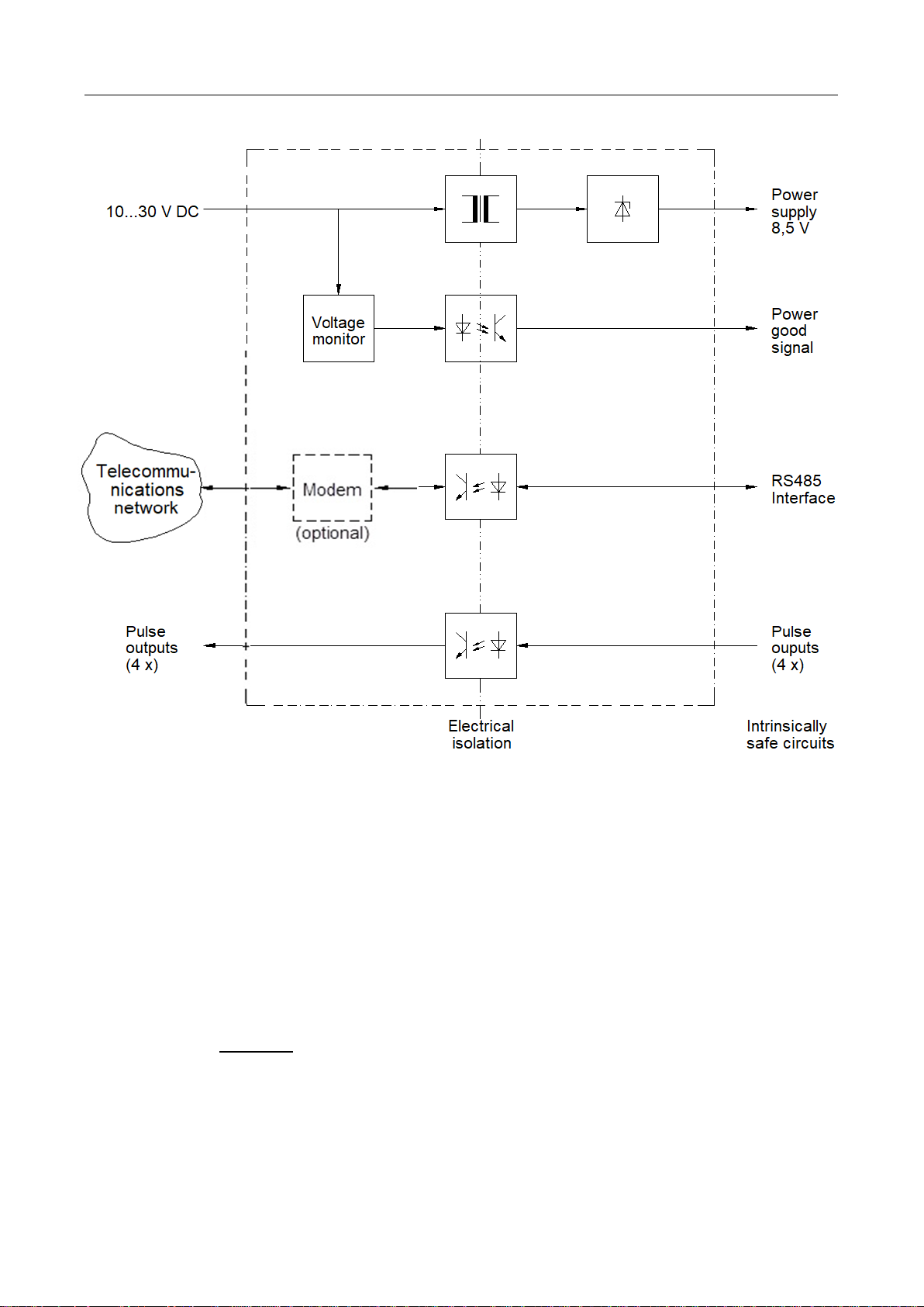
FE260 Operating Manual 5
Fig. 2: Block diagram of FE260, "DC" version.
Two signalling lamps fitted to the cover indicate the following states:
• “Power”: The device is ready for operation.
• “Online”: Data transmission is running via the installed or connected modem. Data is being
transmitted between the connected volume corrector and the readout station or control
station over a telecommunications network.
At the start of a remote data transmission "Online" flashes with the ringing tones which
the modem receives.
In case of a GSM/GPRS modem:
- slow flashing → modem is registered to GSM network
- fast flashing → data transmission in progress
Attention: The function of the yellow "Online" LED differs depending on the GSM / GPRS
/ UMTS modem installed in the FE260! For details see section 4.5.
Page 8
6 Operating Manual FE260
2 Mounting
The holes for wall mounting become accessible after opening the housing cover of the FE260. The 4 screws
for fastening the cover can be tighten by a flat head (blade 8 x 1,2 mm) or Phillips head screwdriver size 2.
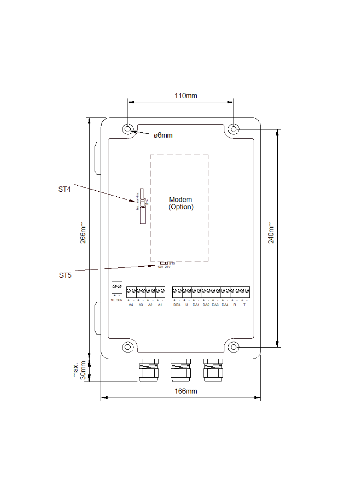
The dimensions, drilling template and diameter of the mounting holes can be taken from Fig. 3 and Fig. 4.
Fig. 3: View from above onto the opened device (here: the "DC" version).
Page 9

FE260 Operating Manual 7
Fig. 4: View from the front onto the cable entries
a = Plastic gland M16 for mains supply 230VAC
b = Blind plug for M12 gland for telephone cable
c = EMC metal glands M20 for data cables to EK2x0
d = SMA antenna socket (for GSM/GPRS antenna)
e = Earth connection
For versions of the FE260 without a GSM/GPRS modem, the hole on position “d” is sealed by a filler plug
and on position “b” a plastic gland M12 is mounted.
!
As “associated electrical equipment”, the FE260 cannot be installed in Zone 1. (See [DIN]
EN 60079-10 and [DIN) EN 60079-14.)
For versions of the FE260 with a GSM/GPRS modem, the supplied antenna must be mounted, e.g. on the
wall. A mounting bracket is provided in the supplied items for this.
e a c d c c c
b
Page 10

8 Operating Manual FE260
3 Installation
!
The terminals of the FE260 are freely accessible on opening the housing. To avoid
damage to the device, it must be ensured that no electrostatic discharge (ESD) from
persons via the FE260 can occur.
To prevent this, the installer should discharge himself by touching an earthed metallic
object directly before connecting a cable.
!
After installation replace all unused cable glands by the enclosed closed-sealing-inserts to
ensure that the housing is sealed. If you don´t use the M16 plastic gland, replace it by the
also enclosed M16 blind plug. That´s the only way to ensure the tightness of the housing!
3.1 Power supply to the FE260
3.1.1 "AC" versions (for alternating voltage 230 V or 115 V)
!
The "AC" versions of the Function Expansion Unit FE260 are supplied with mains voltage
at 230 V or 115 V. Avoid touching live parts, because this can be highly dangerous.
Switch off the mains voltage before starting installation or wire connection work and
before opening the housing.
Only switch the mains voltage on again after all the work has been completed and the
housing has been firmly closed.
Mains alternating voltage should be connected to the terminal block labelled "230V" or "115V" and the earth
conductor should be connected to "PE".
!
Depending on the version, the FE260 is suitable for power supply of 230 V or 115 V
alternating voltage. In order to avoid damaging the device, only connect the voltage
labelled on the terminals.
3.1.2 "DC" version (for direct voltage of 10 to 30 V)
The "DC" version of the FE260 is suitable for a direct-voltage power supply in the range from 10 to 30 V. It
can be operated, for example, with nominal voltages of 12 V or 24 V.
The "DC" version (not the "AC" versions) have the possibility of monitoring the supply voltage on the terminal
"10...30V". In this respect, the terminal "DE3" must be connected to the terminal of the same name on the
volume corrector. (→ 0
Terminal layout, page 11).
The monitoring can be set for nominal voltages of 12 V and 24 V. For further details: see Chapter 4.1.
3.2 Screening and earthing
The cables for connection to the intrinsically safe electrical circuits (blue terminal block) and to the outputs
A1 to A4 have a screen which must be earthed at both ends to prevent interference due to high frequency
electromagnetic fields.. The screen must be connected all round, complete and flat. The FE260, similar to
the volume corrector (e.g. EK260 or EK280) to be connected, has special metallic EMC cable glands for this.
Page 11

FE260 Operating Manual 9
3.3 Intrinsically safe electrical circuits
The FE260 is approved according to DIN EN 50020 as “associated electrical equipment” in the Category “ia”
(see Chapter A-2). The blue terminal block on the right-hand side includes three intrinsically safe circuits. If
an intrinsically safe device is connected to them (e.g. an EK260 or EK280 volume corrector) which is located
in the area subject to explosion hazards (Zone 1), then the appropriate regulations must be followed. The
implications of this include:
!
Follow the stipulations in the relevant regulations and standards, in particular DIN EN
60079-14 (VDE 0165 Part 1) and DIN EN 50014.
!
Make sure that the limits quoted in the certificate of conformance (Chapter A-2) do not
exceed the limits quoted in the certificate of conformance for the intrinsically safe device
to be connected.
!
Only cable may be used for the intrinsically safe electrical circuits which fulfils the
following requirements according to DIN EN 60079-14, Section 12.2.2.1:
Insulated cables with a proof voltage of at least 500 VAC between conductor-earth,
conductor-screen and screen-earth.
If fine-stranded conductors are used, the conductor ends must be protected against
splaying out, e.g. by the use of wire-end sleeves.
The diameter of individual conductors as well as single wires in fine-stranded conductors
must not be less than 0.1 mm.
!
Since the cable screens are connected at both ends, the volume corrector housing must
be electrically connected to the earthed housing of the FE260 via a potential equalisation
conductor. The potential equalisation conductor must have a cross-sectional area of at
least 4 mm². (DIN EN 60079-14, Sect. 12.2.2.3).
The FE260 is earthed using terminal "e" in Fig. 4 (page 7).
Furthermore all other relevant requirements in DIN EN 60079-14 must be fulfilled.
Screened cables must be used for reasons of electromagnetic compatibility (EMC). In this respect, labelling
of the cables or a special sheath colour is not necessary according to DIN EN 60079-14, Sect. 12.2.2.6.
Page 12

10 Operating Manual FE260
3.3.1 Cables and cable lengths
The cable length between the FE260 and the volume corrector (intrinsically safe circuits) may be up to 1000
m depending on the application. The following table provides an overview of the requirements, settings and
limits depending on the cable length:
Cable length up to:
10 m
100 m
500 m
1,000 m
Rem.
Cable cross-sectional area for power supply
(Terminal “U”)
0.5 mm2
0.5 mm2
1.5 mm2
1.5 mm2
*1)
Max. transmission speed
(Terminals “R” and “T”)
19200 Bd
19200 Bd
19200 Bd
9600 Bd
*2)
Max. frequency on Outputs 1, 3, 4
(Terminals “DA1”, “DA3”, “DA4”)
10 Hz
10 Hz
1 Hz
1 Hz
*3) *5)
Maximum frequency on Outputs 2, 3
(Terminal “DA2”)
500 Hz
50 Hz
5 Hz
5 Hz
*4) *5)
*1) For cable lengths up to 100 m a total of two cables 4 x 2 x 0.5 mm² are sufficient for all intrinsically safe
electrical circuits. With a cable length of more than 100 m a separate cable 2 x 1.5 mm² must be laid for
the power supply to the volume corrector (Terminal “U”). The total diameter of each cable must not
exceed 10 mm.
*2) The transmission speed is set on the volume corrector under “Bd.S2” (address 02:0708.0). With an
FE260 with the option "Local interfaces" or "CL interface" the baud rate must be set to 9600 Bd
irrespective of the cable length. With "CL interface" also lower baud rates are possible.
*3) With long cables (clearly noticeable from about 100 m) the pulse-space ratio is degraded by the cable
capacity: The space (output transistor blocking) is shortened and the pulse (output transistor conducting)
is lengthened correspondingly.
If this effect causes problems, the pulse duration and the period (and also therefore the space duration)
can be altered for the volume corrector outputs with the aid of the “enSuite” parameterising program.
Example:
The standard setting is: Period 1000 ms, pulse duration 500 ms (giving a space also of 500 ms).
With a cable length of 1000 m the space is typically shortened by about 250 ms and the pulse is
lengthened by about 250 ms. The space duration is therefore about 250 ms and the pulse duration about
750 ms.
If the (theoretical) pulse duration is set to 250 ms instead of 500 ms with the period unchanged, then
actual pulse and space durations each of 500 ms are produced again including the degradations.
*4) Output 2 (“DA2”) can also be operated, as can all other outputs, as a low frequency pulse output with a
frequency up to 10 Hz. Furthermore, some volume correctors in the LIS-200 range, such as the EK2601
and EK280, offer the possibility of operating Output 2 as a high frequency output at up to 500 Hz. The
connection “DA2” on the FE260 is specially rated for this. Consequently, the above mentioned
degradation of the signal (see *3) is substantially less here.
*5) In case of FE260 manufactured since January 2014, output 3 (“DA3”) can be used for signals up to 500
Hz. The EK280 offers the ability to operate not only output 2 but also output 3 (“DA3”) as a high
frequency output under the same conditions as described for output 2 (refer to *4).
!
The cable cores must be stripped 11 mm. They must be inserted into the terminal over a
length of 14 mm. Take care that only one core is inserted into each clamp!
1
Only EK260s with a date of manufacture from July 2004 onwards.
Page 13

FE260 Operating Manual 11
3.3.2 Terminal layout
With an EK260 or EK280 volume corrector, set “TypS2” = “2” before you connect it to
the FE260 in order to avoid damage to the devices.
Cable 1
FE260
White
Volume corrector
e.g. EK260 or EK280
U
+
+
Uext
Brown
-
-
Green
R
+
+
R
Yellow
-
-
Grey
T
+
+
T
Pink
-
-
Blue
„DC“ version only
DE3
+
+
DE3
Red
-
-
White
DA1
+
+
DA1
Brown
-
-
Green
DA2
+
+
DA2
Yellow
-
-
Grey
DA3
+
+
DA3
if present
Pink
-
-
Blue
DA4
+
+
DA4
Red
-
-
Cable 2
On the EK260 and EK280 the terminals “R+”, “R-“, “T+” and “T-“ are also labelled with “CS”, “RD”, “RS” and
“TD”. When connecting the FE260, these designations have no significance. The terminals “Ri” and “Gnd” on
the EK260 remain unconnected.
The cable designations (Cable 1 and Cable 2) and the suggested core colours are based on the use of two
similar cables, LiYCY 4 x 2 x 0.5 mm², twin-twisted with colour code according to DIN 47100. Suitable cables
can also be obtained from Elster-Instromet (see II-2, Options).
With "AC" versions (with 230V or 115V power supply) the blue and red wires of Cable 1 remained unused.
They should then be cut off at both ends flush with the cable sheath or safely insulated to prevent hazardous
short circuits from forming.
Of course, other cables can also be used provided they conform to the requirements quoted in 0. Similarly, a
different designation of the core colours is possible.
3.4 Digital Outputs A1 to A4
The terminals “A1” to “A4” are individually electrically isolated digital outputs which pass on the incoming
signals on “DA1” to “DA4” (pulse or message signals) from the volume corrector unmodified with respect to
time. Due to the approved electrical isolation, any devices without Ex approval can be connected to A1 to A4,
provided they do not exceed the limits quoted in the chapter “Technical Data”.
Page 14

12 Operating Manual FE260
The connection is made
according to the following
configuration:
Wire colour
white
a
RX-
brown
b
RX+
pink
a2
TX-
grey
b2
TX+
3.5 Data transmission modules
On request, the FE260 can be fitted with an integral modem, a connection for a separate modem or an
Ethernet interface in order to read out the data from the connected volume corrector by remote data
transmission. Various modules are possible (refer to sections 3.5.1 et seqq.).
For data transfer via the FE260 the EK260 requires at least the software version 2.02.
3.5.1 Integral standard modem
The standard modem is used for connection to the analogue telephone network (PSTN1 subscriber socket,
not ISDN2). With the FE260 with integral standard modem, the connection cable with a TAE subscriber plug
is already mounted on the terminal clamps.
The respective connection cable is passed through the smaller plastic gland at the top centre (→ position “b”
in Fig. 4, page 7).
1
Public Switched Telephone Network
2
Integrated Services Digital Network
Page 15

FE260 Operating Manual 13
3.5.2 Integral GSM/GPRS/UMTS modem
The FE260 can be optionally equipped with a GSM1/GPRS2 (2G) or a UMTS3 modem (3G). The modems are
used for data transmission via the GSM/GPRS or UMTS network (radio network, “mobile phone network”).
With the FE260 with an integral GSM/GPRS modem the antenna required for this is included in the supplied
items.
Similarly, a mounting bracket for mounting the antenna (e.g. on the wall) is also included in the supplied
items.
Once the antenna has been mounted, the antenna cable has to be connected to the SMA4 socket on the
bottom side of the housing (→ Fig. 4, pos. “d”, page 7).
To operate the modem you need a SIM5 card from your provider (e.g. D1 or D2 network).
In case the data transmission should be originated by an analogue PSTN6 data modem, the CSD7 service
must be enabled by the network provider. If in doubt, please contact your network provider.
Disconnect the FE260 from the power supply before you insert the SIM card into the
SIM holder.
Then close the SIM holder carefully, close the housing and switch on the power supply
again.
Disconnect the FE260 from the power supply before you mount or dismount the
antenna!
Take care that the FE260 is in secure area (non Ex) before you mount or dismount the
antenna!
1
Global System for Mobile Communications
2
General Packet Radio Service
3
Universal Mobile Telecommunications System
4
Sub-Miniature-A, coaxial antenna socket
5
Subscriber Identity Module
6
Public Switched Telephone Network
7
Circuit Switched Data
Page 16

14 Operating Manual FE260
Automatic call acceptance in the
modem
EK260
Md.S2 (Adr. 2:705)
EK280
MdxS2 (Adr. 2:706)
off (ATS0=0)
3
4 („Standard AT“)
on (ATS0>0)
5
0 („Transparent“)
Before connecting a commercially available modem to the RS-232 interface, make sure
that the jumper in the vicinity of the modem connection terminals is plugged on the side
labelled “RS-232”.
Clamp
Wire colour 1
SUB-D9 socket
Pin no.
FE260
brown
Modem
RxD
2
RxD
green
TxD
3
TxD
white
DSR / DCD / CTS
1
DCD
yellow
DTR / RTS
4
DTR
pink
RI
9
RI
grey
GND
5
GND
3.5.3 Connection of a separate modem
If the FE260 is implemented with a connection for a separate modem, you can connect a commercially
available modem to it to read out the volume corrector by remote data transmission. You can use a modem
with or without automatic call acceptance.
A modem without automatic call acceptance must be parameterised such that it sends the text “Ring” over
the data line to the volume corrector for each ringing tone (for each “ring”). This then causes the modem to
accept the call (“lift receiver”) after the set number of ringing tones (“Num.T”, → 0 in Chapter 4.3).
Depending on the connected modem, “Md.S2” (MdxS2 respectiveley) should be set in the volume corrector
according to the following table:
The modem connection in the FE260 can be configured as an RS-232 or RS-485 interface. To enable this,
there is a jumper labelled “RS-232” and “RS-485” on the board with the terminals for the modem connection.
Connection diagram:
The modem signals “DCD”, “DTR” and “RI” are not used by the FE260. These terminals may be connected
or left unconnected. Connection of “RxD”, “TxD” and “GND” is needed.
3.5.4 Integral Ethernet interface
The Ethernet interface is used for connection to a LAN2 or to a DSL3 modem.
The Ethernet interface is only supported by new volume converters such as EK280 as of software version
2.51 or EK205 as of software version 1.10. Older volume converters such as EK260 are not compatible.
For connection and commissioning of the Ethernet interface, please proceed as described in the application
manual of the device to be connected (e.g. EK280 or EK205).
1
The colours corresponds with the Elster modem cable with ID no. 73016923
2
Local Area Network
3
Digital Subscriber Line
Page 17

FE260 Operating Manual 15
4 Initial operation
For initial operation the following steps should be carried out:
4.1 Power supply
• Once all cables are connected and the housing firmly closed, switch on the FE260 power supply (mains
voltage for the "AC" versions).
• Check the “Power” signal lamp on the cover of the FE260. A continuous green signal indicates that the
FE260 power supply is functioning correctly.
• Check the power supply of the connected volume corrector by bringing the status messages into the
volume corrector display. If the message “Batt. operat” (message "15" in status "St.SY") is not entered
here, the volume corrector is being supplied from the FE260.
If the volume corrector displays the message "Batt. operat" (message "15" in "St.SY", the volume
corrector is not being supplied from the FE260. In this case check that the intrinsically safe electrical
circuits are connected correctly.
Only the "DC" version (not the "AC" versions) have the possibility of monitoring the supply voltage on the
terminal "10...30V". When a voltage limit is undercut, the connected volume corrector receives a
corresponding signal through the "DE3" terminal, setting the status message "8" in the status "St.3" of the
volume corrector. Due to this status signal, the volume corrector can for example, with appropriate
parameterisation, then activate an output or execute another event-controlled action.
If you would like to use the voltage monitoring of the "DC" version, carry out the following steps:
• Set the voltage limit with jumper "ST5" (→ Fig. 3, page 8) appropriate to your power supply:
- to the position "12" for power supply with a nominal voltage of 12 V
(The limit for the warning is then approx. 11 V.)
- to the position "24" for power supply with a nominal voltage of 24 V
(The limit for the warning is then approx. 20 V.)
• Make sure also that the terminal "DE3" is connected to the terminal of the same name on the volume
corrector. (→ 3.3.2 Terminal diagram, page 13).
• On the volume corrector set the value "MdME3" (in the display column "Inp."
• If the monitoring does not function, also check the following values in the display column "Inp." on the
1
) to "3".
volume corrector:
- SC.I3
2
= 0003:228_0 ("St.I3")
- L1.I3 = 1
- SpI3 = 0.08_03:1.1 ("I3 Warn.sig↑“)
1
on EK280 under “→ Inputs → Input 3”
2
on EK280: “ScMI3”
Page 18

16 Operating Manual FE260
4.2 Digital outputs
If you are using digital outputs, check whether the devices connected to terminals A1 to A4 are receiving the
volume corrector signals.
If this is not the case, then check:
• the output settings of the volume corrector according to its operating manual and the details in Chapter
3.3.1.
• by how far the technical data for the outputs (Chapter B) match the connected device.
• whether all specifications regarding cables and cable lengths in Chapter 0 have bee fulfilled.
• whether the signal inversion of the outputs may possibly be incorrectly set (see above).
• The transfer of an HF signal via output "DA2" functions with an EK260 with a date of manufacture from
July 2004 onwards and furthermore with all EK280.
• The transfer of an HF signal via output "DA3" functions only with EK280 in conjunction with a FE260 with
a date of manufacture from January 2014 onwards.
Signal inversion
With the aid of the jumper "ST4" (→ Fig. 3, page 8) you can set whether the output signals are inverted with
respect to those supplied by the volume corrector.
• Position "non-inv." The signals are not inverted (standard setting).
• Position "inv." The signals are inverted.
"Inverted" signifies that the FE260 output is switched through (conducts) when the volume corrector output
blocks and vice versa.
Page 19

FE260 Operating Manual 17
4.3 Modem
When using an integral or connected modem, the interface of the volume corrector (except EK2801) must be
parameterised as follows:
AD2
Address
Designation
Setting
Meaning
Rem.
Md.S2
2:0705
Mode
3 or 5
*1)
DF.S2
2:0707
Data format
0
7 data bits, even parity, 1
stop bit ("7e1")
Bd.S2
2:0708
Initial baud rate
19200 or 9600 baud
*2)
TypS2
2:070A
Type of interface
2
RS-485
*3)
Num.T
2:0720
Rings before call accept.
*4)
CW1.S
5:0150
Call Time Window 1 Start
*5)
CW1.E
5:0158
Call Time Window 1 End
CW2.S
6:0150
Call Time Window 2 Start
CW2.E
6:0158
Call Time Window 2 End
1:01FB
Activation with external power
supply
1
Remains continuously active
*6)
2:0709
"Identification baud rate"
19200 or 9600 baud
*2), *6)
*1) When using a modem without automatic call acceptance (standard case), Md.S2 = “3” must be set and
MD.S2 = “5” for modems with automatic call acceptance (e.g. with an FE260 with the option "Local
interfaces" or "CL interface").
*2) 19200 Bd is standard. With longer lengths of cable between the FE260 and the volume corrector (refer
to Chapter 0, page 10) and when using the option "Local interfaces" or "CL interface", the baud rate may
be set to a maximum of 9600 Bd.
When using an FE260, the starting baud rate "Bd.S2" and the "Identification baud rate" (address 2:0709)
must always be set to the same value.
*3) The setting of the type of interface is only needed with those types of volume corrector where “TypS2” is
present in the display (e.g. EK260).
*4) The adjustable number of ringing tones (rings) before call acceptance depends on the modem used.
With a GSM modem it must be set to "2" and with other modems to a value between "2" and "9".
With a modem with automatic call acceptance, “Num.T” has no significance.
*5) Volume correctors in the LIS-200 range, such as the EK260 and EK280, offer at least two time windows
within which calls can be accepted for data interrogation. Outside of these time windows calls are
ignored, so that, for example, a person located in the station can be called via a telephone connected to
the same telephone line.
*6) The values with the addresses 1:01FB and 2:0709 are not always available in the volume corrector
display. They can be changed, for example, via the optical interface using the parameterisation software
"enSuite". The standard setting is “1:01FB = 1” and "2:0709 = 19200".
1
Please parameterize the EK280 according its Application Manual
2
Abbreviation in the interface menu “Ser.IO” in the display of the volume corrector
Page 20

18 Operating Manual FE260
4.3.1 Problems during data transfer and solutions
If, after connecting the cables and setting the parameters, the data transmission via the modem does not
work, check the following points:
1. Does the signal "Power" light on the housing cover of the FE260?
→ If not, make sure that the FE260 power supply is connected correctly and switched on.
2. Does the volume corrector indicate the status message "Bat. operat.". (With older versions message "15"
in the status "St.Sy")
→ Connect the terminals "U+/-" of the FE260 correctly to the terminals "Uext+/-" on the volume
corrector.
In addition you can also measure the voltage on the terminals "U+/-" of the volume corrector with a
multimeter. It should be approx. 8.5 V.
3. Does the volume corrector display the status message "Call Win.1" or "Call Win.2"?1 (Message "16" in the
status "St.1" or "St.2")
→ Calls can only occur within one of the time windows. If none of the above messages are displayed,
set the time window according to your requirements. You can set the time window with the values
"CW1.S", "CW1.E", "CW2.S", "CW2.E" in the display column "Ser.IO" of the volume corrector.
4. Is the modem parameterization in the FE260 correct?
→ The modem must be suitably parameterized in correspondence with the interface mode in the
volume corrector:
Interface mode in EK2x0
Automatic call acceptance in the modem
EK260
Md.S2 (Adr. 2:705)
EK280
MdxS2 (Adr. 2:706)
3
Standard AT
off (ATS0=0)
5
transparent
on (ATS0>0)
With "Md.S2 = 3" (respectively MdxS2 = “Standard AT”) the modem may not pickup an incoming call
automatically. A call is only accepted after the volume corrector has sent the corresponding pickup
command “ATA” to the modem. This happens after the EK2x0 has received the number of RING
messages, which is specified by the setting Num.T, address 2:720.
With "Md.S2 = 5" (respectively MdxS2 = “transparent”) the modem has to accept incoming calls
automatically after the number of ring signals, which is specified in register 0 by the command
ATS0=x (where “x” is the number of ring signals).
If the FE260 is fitted with the option "Local interface" or "CL interface", the modem must accept the
calls automatically.
→ If a modem has been retrofitted, which was intended for a different device (e.g. DL240), the modem
parameterization may need to be changed.
5. When "Md.S2" in the volume corrector is set to "3" (respectively “MdxS2 = “Standard AT”): Does the
signal "online" on the housing cover of the FE260 illuminate or flash?
→ If not, check whether you have entered the correct telephone number for the call in your data recall
software (e.g. "enSuite"). A telephone exchange may also require a leading zero.
Only when using a radio modem (GSM/GPRS/UMTS modem):
If the FE260 "online" signal slowly flashes, the following possible faults are eliminated and do not need to be
checked.
Otherwise, check the following points:
6. Is the antenna correctly connected to the modem?
→ Insert the antenna connection firmly into the modem.
1
On EK280 the call acceptance windows 5 and 6 are used for the connections via FE260 (refer to the EK280
Application Manual)
Page 21

FE260 Operating Manual 19
7. Is a suitable SIM card inserted into the modem?
→ Possibly the CSD1 service must be enabled by the network provider (please refer also to section
3.5.2).
8. If the PIN is activated on the SIM: Was the correct PIN entered in the EK2x0?
→ Possibly the PIN query has to be disabled on the SIM. This can be done by temporarily inserting the
SIM in a mobile phone.
→ In case of an EK260 till V2.40 the PIN query may cause problems. If in doubt, please disable the PIN
query!
9. Is the mobile radio network (GSM network) strong enough?
→ Check whether the data transmission functions correctly when you mount the FE260 at another point
or connect an external antenna or locate the external antenna at another position.
10. Are there interference sources in the vicinity of the FE260 or the antenna?
→ Check whether the data transmission functions correctly when you mount the antenna at another
point (this may need to be repeated).
4.3.2 Parameterisation of the modem integrated into the FE260
Modems installed in the FE260 are parameterised at the Elster factory for operation with a volume corrector,
so that on-site parameterization is usually no longer necessary.
If a GSM/GPRS or a UMTS modem is installed in the FE260, this can be re-parameterized later on via the
DSUB9 socket on the modem module. To do this, the jumper "Mode" at the top right of the modem module
must be plugged to the lower position "Program". Then the modem can be addressed using a PC or laptop.
For this purpose a serial interface of the PC or laptop has to be connected to the DSUB9 socket of the
modem module. The modem parameterisation can then be carried out, for example, with the aid of the
program "Modemini" from V3.52.
The modem parameterisation should only be carried out by experienced specialist personnel. In
cases of doubt obtain the help of a service technician from Elster-Instromet.
4.3.3 Test mode
If a GSM / GPRS or a UMTS modem is installed in the FE260, the transmission data of the modem and the
volume converter are simultaneously output to the send data line of the DSUB9 socket on the modem
module. In this operating mode, communication between the built-in modem and the connected volume
converter can be monitored using a so-called "terminal program". This function can be used by experienced
personnel to commission the FE260.
4.4 Integral Ethernet interface
The Ethernet interface is used for connection to a LAN2 or to a DSL3 modem.
The Ethernet interface is only supported by new volume converters such as EK280 as of software version
2.51 or EK205 as of software version 1.10. Older volume converters such as EK260 are not compatible.
For connection and commissioning of the Ethernet interface, please proceed as described in the application
manual of the device to be connected (e.g. EK280 or EK205).
1
Circuit Switched Data
2
Local Area Network
3
Digital Subscriber Line
Page 22

20 Operating Manual FE260
4.5 Function of the light-emitting diodes (LED)
The function of the online LED on the lid of the FE260 as well as the LEDs on a GSM / GPRS / UMTS
modem module depends on the built-in modem type. Which modem type is installed can be distinguished by
the modem sticker as follows:
Modem type
ECM-GW120
ECM-2G-UG350
ECM-3G-UU270
Build
4/2014 – 9/20171
since 10/2017
Appearance
of the
assembly
Sticker
GW120 Ex-Z2
ECM-2G-UG350
ECM-3G-UU270
4.5.1 Function of the LEDs on the lid of the FE260
LED
Status
Meaning
Power
off
Power supply switched off
on
Power supply switched on
Online
With PSTN modem or Ethernet adapter
off
No data connection active
on
data connection active
With GSM/GPRS-Modem „ECM-GW120“
off
No GSM network
flashing
• Slow flashing (0,45 Hz, 2 sec on, 0.2 sec of means:
Registered to the GSM network, no data connection („offline“)
• Fast flashing (1,25 Hz, 0.6 sec on, 0.2 sec of) means:
Establishing a data connection
on
data connection active („online“)
With GSM/GPRS “ECM-2G-UG350” or UMTS modem “ECM-3G-UU270”
off
Power supply switched off
on
a) Power supply switched on, no call acceptance window active
b) CSD or TCP connection active
Remark:
• To distinguish cases a) and b), the LED1 "GSM" must be used on the modem
module! (refer to chapter 4.5.3)
• Since the FE260 is connected to the mains, a call acceptance window can always
be open. This means that normally only the states "flashing" (registered, no data
connection active) and "on" (data connection active) must be distinguished!
flashing
Modem registered to the GSM network, no data transmission aktive
Remark: The online LED flashes inversely to the LED1 "GSM" on the respective
modem module, refer to chapter 4.5.3
1
As retrofit kit for operation in FE260 on EK260 also available after 9/2017 (while stocks last!)
Page 23

FE260 Operating Manual 21
4.5.2 Function of the light-emitting diodes on the SVB board of the FE260
LED
Status
Meaning
TxD
off
No data is sent
on
Data is sent
RxD
off
No data is received
on
Data is received
4.5.3 Function of the light-emitting diodes on the GSM/GPRS/UMTS modem
4.5.3.1 Function of the LEDs on a “ECM-GW120”
LED
no GSM
network
Registered to GSM
network, no data
connection („offline“)
During
establishing a
data connection
Data connection active
(„online“)
LED1 GSM
on
flashing slowly1
flashing fast2
GSM: flashing fast24
GPRS: flashing slowly23
LED2 GPRS
on
flashing slowly23
flashing fast24
GSM: on
GPRS: flashing fast24
LED3 DCD
off
off
off
on
LED4 RI
off
off
flashing
off
LED5 TxD
off
off
off
flickering (send data)
LED6 RxD
off
off
off
flickering (receive data)
4.5.3.2 Function of the LEDs on a “ECM-2G-UG350” or “ECM-3G-UU270)
Depiction „LED status → Modem status“:
LED
Status
Meaning
GSM
off
Modem not registered to the GSM network
on
The modem is currently registering
CSD or TCP connection active
flashing
Modem registered, no CSD or TCP connection active
„Single“ flashing, slow (100ms on, 2s off)
→ Modem registered to the GSM home network
„Double“ flashing, slow (100ms on, 100ms off, 100ms on, 2s off)
→ Modem registered to the GSM network with roaming
„Double“ flashing, fast (50ms on, 50ms off, 50ms on, 2s off)
→ Modem registered to the UMTS home network (UMTS modem only)
Fast continuous flashing (50ms on, 50ms off, 50ms on, 100ms off)
→ Modem registered to the UMTS network with roaming (UMTS modem only)
GPRS
off
No GPRS session active
on
GPRS session active
DCD
off
No CSD or TCP socket connection active
on
CSD or TCP socket connection active
RI
off
No incoming call
on
Incoming CSD or TCP call
TxD
off
No data is sent
on
Data is sent
RxD
off
No data is received
on
Data is received
1
Slow flashing: 0,45 Hz, 2 sec off, 0.2 sec on
2
Fast Blinken: 1,25 Hz, 0.6 sec off, 0.2 sec on
Page 24

22 Operating Manual FE260
Alternative depiction „Status FE260 / Call acceptance window / Modem → LED stati“:
Status
FE260 /
call acceptance windows /
modem
Status of the light-emitting diodes
On the lid of the
FE260
On the GSM/GPRS or UMTS modem module
Power
Online
LED1
GSM
LED2
GPRS
LED3
DCD
LED4
Ri
LED5
TxD
LED6
RxD
FE260 off
off
off
off
off
off
off
off
off
Switch on FE260, both call acceptance windows 5 + 6 closed1, PIN active → Modem remains unregistered
Modem unregistered
on
on
off
off
off
off
off
off
Switch on FE260, both call acceptance windows 5 + 6 closed25, PIN inactive → Modem registers automatically
Modem registered
on
flashs2
flashs 3
off
off
off
off
off
Open one of the call acceptance windows 5 or 6 during the FE260 is switched on
→ Modem registers
During registering
on
flickers
off /on 4
off
off
off
flickers
flickers
GSM operation (no APN data entered)
Registered to GSM network,
no GPRS session,
no CSD connection
on
flashs
26
flashs 27
off
off
off
off
off
incoming CSD-Call
on
off
on
off
off
flashs 5
off
off
Registered to GSM network,
no GPRS session,
CSD connection active
no data transmission
on
on
on
off
on
off
off
off
Registered to GSM network,
no GPRS session,
CSD connection active
during CSD data transmission
on
on
on
off
on
off
flickers
flickers
GPRS operation (valid APN data entered)
Registered to GSM network,
GPRS session active,
no CSD connection,
no TCP connection
on
flashs
26
flashs 27
on
off
off
off
off
Incoming TCP-Call
(establish TCP socket)
on
flashs
26
flashs 27
on
off
flashs 6
off
off
Registered to GSM network,
GPRS session active,
TCP socket connection active,
no data transmission
on
on
on
on
on
off
off
off
Registered to GSM network,
GPRS session active,
TCP socket connection active,
during TCP data transmission
on
on
on
on
on
off
flickers
flickers
1
Because the FE260 is always supplied by mains, typically one of the call acceptance windows 5 or 6 is always open.
2
Flashes invers to LED1 „GSM“
3
„Single“ flashing (100ms on, 2s off) → Modem registered to the 2G home network
„Double“ flashing (100ms on, 100ms off, 100ms on, 2s off) → Registered, 2G roaming
„Double” flashing, fast (50ms on, 50ms off, 50ms on, 2s off) → Registered, 3G home network
Fast continuous flashing (50ms on, 50ms off, 50ms on, 100ms off) → Registered, 3G roaming
4
Off until the PIN is entered, then on
5
Flashes 1x for each ring tone (according menü item „Serv. – interface – Clamp interface. – Num.T“, in case off
GSM/GPRS and UMTS modem typically Num.T=2)
6
Flashes 1x shortly
Page 25

FE260 Operating Manual 23
A Approvals
A-1 EC Declaration of Conformance
Page 26

24 Operating Manual FE260
A-2 Approval as associated operating equipment
Page 27

FE260 Operating Manual 25
Page 28

26 Operating Manual FE260
Page 29

FE260 Operating Manual 27
Page 30

28 Operating Manual FE260
B Technical data
B-1 General data (mechanical and ambient conditions)
Housing/structure ...........................
Wall-mounted housing,
Aluminium cast alloy G AI SI 12 / DIN 1775
Dimensions (W x H x T) .................
approx. 290 x 175 x 102 mm
with cable entry glands and hinges
Cable union glands ........................
Suitable for cables with overall diameter 6...10 mm
Weight ............................................
approx. 3 kg
Protection .......................................
IP 65 according to EN60529
Ambient temperature .....................
„AC“ versions: 0°C ... +40 °C
„DC“ version: -10°C ... +60 °C
Climatic conditions .........................
Relative humidity max. 93%, non-condensing
B-2 Power supply
Designation ....................................
„230V“ („AC“ version 230 V)
„115V“ („AC“ version 115 V)
„10...30V“ („DC“ version)
Cable connection ...........................
Screw terminals, green, for
Cable cross-sectional area ............
solid wires 0.14...2.5 mm²
flexible stranded wire 0.14...1.5 mm²
Fit wire-end sleeves to flexible stranded wires
Screening .......................................
No cable screen required
Voltage ...........................................
230 V AC +10% / -15% („AC“ version 230 V)
115 V AC +10% / -15% („AC“ version 115 V)
10 V DC to 30 V DC („DC“ version)
Power consumption .......................
3 W max. (with modem)
B-3 Connection cables and cable glands
In order to ensure the IP protection class 65 according to EN60529 even when all connection cables are
mounted, the values in the following table must be taken into account:
Cable gland
Valid cable diameter
range
Torque for tightening the
gland
Metric wrench size of
open-end wrench
Plastic cable gland M16
(page 9, fig. 4. pos. „a“)
7 … 8 mm
2,5 Nm
22 mm
Plastic cable gland M12
(page 9, fig. 4. pos. „b“)
5 … 6 mm
1,5 Nm
15 mm
Metal cable gland M20
(page 9, fig. 4. pos. „c“)
7 … 8 mm
10 Nm
20 mm
Take care that only one core is inserted into each clamp!
The cable cores must be stripped 11 mm. They must be inserted into the terminal over a length of 14 mm!
Page 31

FE260 Operating Manual 29
B-4 Intrinsically safe power supply for the volume corrector
Also suitable for supplying the EK260 volume corrector.
Designation ....................................
“U”
Cable connection ...........................
Screw terminals, blue
Cable cross-sectional area ............
0.5...1.5 mm²
Fit wire-end sleeves to flexible stranded wires
Cable length
for cable of cross-sectional
area: 1.5 mm2 ...................
1,000 m max.
0.5 mm2 ...................
100 m max.
Screening .......................................
Connect cable screen to the cable gland over the full area
Voltage ...........................................
8.5 V 5 %
Current ...........................................
40 mA max.
Safety limits ...................................
(see Declaration of Conformance A-2)
B-5 Connections for volume corrector digital outputs
Suitable for pulse or message outputs.
Connection “DA2” is also suitable for higher frequencies, e.g. for the transmission of a frequency proportional
to the flow.
Designation ....................................
“DA1”, “DA2”, “DA3”, “DA4”
Cable connection ...........................
Screw terminals, blue
Cable cross-sectional area ............
0.5...1.5 mm²
Fit wire-end sleeves to flexible stranded wires
Cable length ...................................
1000 m max. depending on frequency (see below)
Screening .......................................
Connect cable screen to the cable gland over the full area
Open-circuit voltage .......................
5 V 10 %
Short-circuit current
DA1, DA3, DA4 .........................
5 A max.
DA2 ...........................................
30 A max.
Frequency
DA1, DA3, DA4
for cable length
up to 100 m .................
10 Hz max.
up to 1,000 m .................
1 Hz max.
DA2
for cable length
up to 10 m .................
500 Hz max.
up to 100 m .................
50 Hz max.
up to 1,000 m .................
5 Hz max.
Safety limits ...................................
(see Declaration of Conformance A-2)
Page 32

30 Operating Manual FE260
B-6 Serial data interface to the volume corrector
Intrinsically safe RS-485 interface for four-wire operation
Designation ....................................
“R” (received data), “T” (sent data)
Cable connection ...........................
Screw terminals, blue
Cable cross-sectional area ............
0.5...1.5 mm²
Fit wire-end sleeves to flexible stranded wires
Cable length ...................................
1000 m max. depending on transmission speed (see below)
Screening .......................................
Connect cable screen to the cable gland over the full area
Transmission speed
for cable length
up to 500 m .................
19200 Bd max.
up to 1,000 m .................
9600 Bd max.
Safety limits ...................................
(see Declaration of Conformance A-2)
B-7 Digital outputs
Individually electrically isolated transistor outputs (open collector)
Designation ....................................
“A1”, “A2”, “A3”, “A4”
Cable connection ...........................
Screw terminals, green, for
- solid wires 0.14...2.5 mm²
- flexible wires 0.14...1.5 mm²
Fit wire-end sleeves to flexible stranded wires
Screening .......................................
Connect cable screen to the cable gland over the full area
Switching voltage ...........................
30 V max.
Switching current ...........................
50 mA max.
Voltage drop ..................................
1.5 V max.
Residual current .............................
0.01 mA max.
Frequency
A1, A3, A4 ...........................
10 Hz max. for cable length up to 10 m *
A2 ........................................
500 Hz max. for cable length up to 10 m *
and 40 to 50 mA switching current **
* With a cable length of more than 10 m between the FE260 and the volume corrector (intrinsically safe
electrical circuit) the maximum frequency cannot be guaranteed. (See B-5 and Chapter 0).
** With a smaller load (lower switching current) the frequency which can be transmitted is reduced.
In this case a resistance can be wired in parallel to the load so that in total a switching current of approx.
40 to 50 mA (no more) is produced. The resistance should have a rating of 2 watts or higher.
Note that the switching current at frequencies above approx. 1 Hz cannot be measured with a
commercially available ammeter (multimeter). You can connect an ammeter to the input of the device
which is to be later connected to the FE260 to determine the switching current.
 Loading...