

Page 1
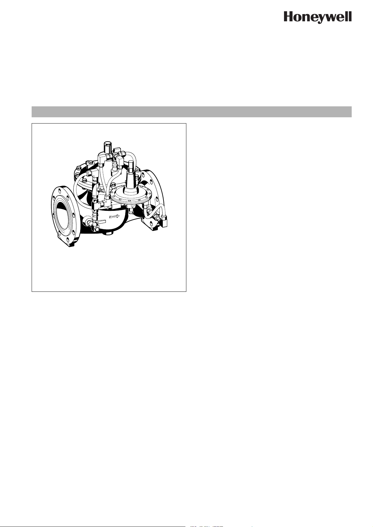
FD300
Altitude control valve
Product specification sheet
Application
Altitude control valve of this type controls the water level in, for
example, water reservoirs without the need for using a float valve
or other ancillary controls.
The highly sensitive pilot valve and the main valve are installed
outside the water reservoir and the pilot valve senses the hydrostatic water pressure from the water level in the reservoir.
The main valve closes when the maximum set pressure for the
pilot valve is reached and reopens when the water level corresponds to the lower set value on the pilot valve.
The standard version permits filling of a water storage unit. A
special version is also available on request which can be used for
both filling and emptying water storage units.
Range of Application
Medium Water
Operating pressure Max. 16 bar
Setting range 0.5 - 5 m water head (Standard version)
Construction
The filling valve comprises:
• Housing with PN16 flanges per ISO7005-2, EN1092-2
• Two-way pilot valve
• Control circuit with ball valves on inlet and outlet
• Control circuit with integral rinsable filter insert
Materials
• Ductile iron housing, cover plate and diaphragm plate
(ISO 1083), powder coated
• Red bronze/stainless steel regulating cone
• Stainless steel pressure spring and control rod
• Fibre-reinforced NBR diaphragm
• NBR and EPDM seals
• Stainless steel valve seat
• High quality synthetic material control circuits
• Brass compression fittings
• Brass pilot valve housing
EN0H-1329GE23 R0807 • Subject to change
• Stainless steel filter insert
Technical Data
Operating temperature
Nominal pressure PN 16
Minimum pressure 0.7 bar
Connection size DN 50 - 450
Max. 80 °C
PN 25 on request
www.honeywell.com 55
Page 2
FD300 Altitude control valve
Method of Operation
At zero pressure the valve is closed. When the system is then put
into operation, the water flows in and opens the diaphragm valve.
This fills the reservoir until the water head corresponding to the
set hydrostatic pressure on the pilot valve is reached and it then
closes. If the pilot valve is closed, the pressure in the chamber
above the membrane rises. The membrane surface area is larger
than the valve surface area and therefore the diaphragm valve
closes. If water is drawn from the water store, the hydrostatic
pressure falls until it reaches the lower set pressure and the pilot
valve then opens. In this way the pilot valve controls the opening
and closing of the main valve.
Options
FD300- ... A = Housing with flange, PN 16,
ISO 7005, EN 1092-2
FD300- ... Z = PN 25, on request
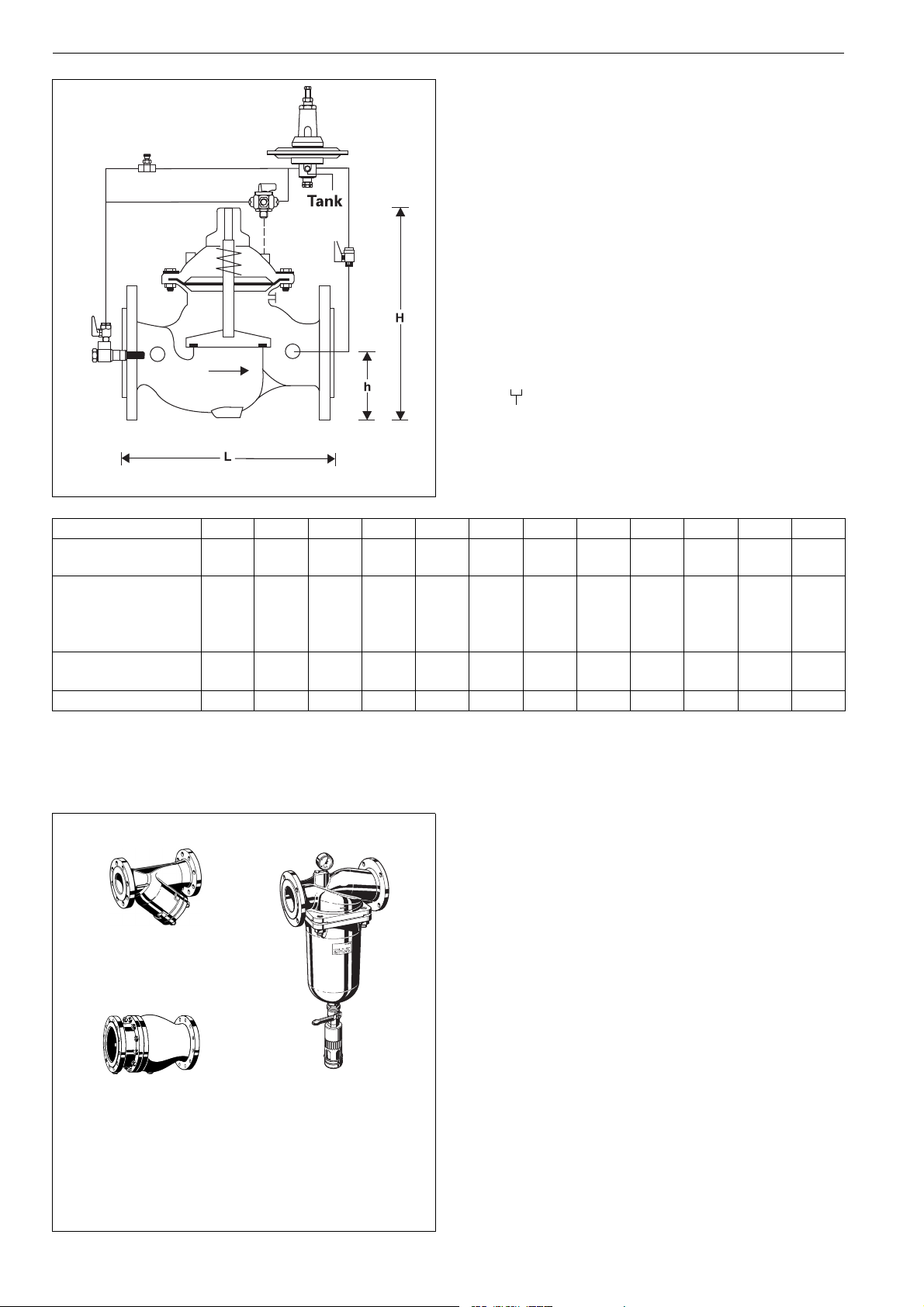
Connection size
Connection size DN 50 65 80 100 150 200 250 300 350 400 450
Weight approx.kg15 16 25 40 83 160 248 408 513 825 948
Dimensions (mm)
Flow rate (Q
) in m3/h
max
L
230
H
235
h
83
292
294
93
310
400
100
350
433
110
480
558
143
600
650
173
730
823
205
850
944
230
980
990
260
1100
1250
290
40 40 90 160 350 480 970 1400 1900 2500 3150
1200
1250
310
- V=5.5 m/s
kvs-value m3/h 43 43 103 167 407 676 1160 1600 1600 3300 3300
Accessories
FY69P Strainer
5
r
15
ba
0
16
With double mesh, grey cast iron housing, powder
coated inside and outside.
A = Mesh size approximately 0.5 mm
F76S-F Reverse-rinsing filter
FY69P
Red bronze housing and filter bowl. Available in sizes
DN 65 to DN 100, with filter mesh sizes 100 µm
or 200 µm
RV283P
56 www.honeywell.com
F76S-F
RV283P Check valve
Grey cast iron housing, powder coated inside and
outside. DIN/DVGW tested in compulsory test sizes
DN 65, DN 80 and DN 100
EN0H-1329GE23 R0807 • Subject to change
Page 3

Installation Example
FD300 Altitude control valve
Installation Guidelines
• Install shutoff valves on both sides of the pressure sustaining
valves
• Install strainer upstream of filling valve
o Protects against damage from coarse dirt
• Note flow direction (indicated by arrow)
• Ensure good access
o Simplifies maintenance and inspection
• The main valve must be installed below the maximum water
level of the water storage facility being filled
• The pilot valve must be at least 2 m below the lowest stored
water level and not more than 50 m below the highest water
level
• Install connectors for removal and refitting for maintenance
Flow Diagram
Typical Applications
Filling valves of this type, within the limits of their specification, are
for water supply installations and also for commercial and industrial applications.
The following are some typical applications:
• Potable water supply
• As filling valves for reservoirs
• For receiver vessels for industrial installations
EN0H-1329GE23 R0807 • Subject to change
www.honeywell.com 57
Page 4

FD300 Altitude control valve
Spare Parts
Altitude control valve FD300, from 2002 onwards
No. Description Dimension Part No.
1
1 Replacement
DN 50 - 450 76-600
pilot valve
2
2 Set of seals DN 50 0903750
DN 65 0903751
DN 80 0903752
DN 100 0903753
DN 150 0903754
DN 200 0903755
DN 250 0903756
DN 300 0903757
DN 350 0903758
DN 400 0903759
DN 450 0903760
2
2
2
2
Automation and Control Solutions
Honeywell GmbH
Hardhofweg
D-74821 Mosbach
Phone: (49) 6261 810
Fax: (49) 6261 81309
http://europe.hbc.honeywell.com
www.honeywell.com
Manufactured for and on behalf of the
Environmental and Combustion Controls Division
of Honeywell Technologies Sàrl, Ecublens, Route
du Bois 37, Switzerland by its Authorised Representative Honeywell GmbH
EN0H-1329GE23 R0807
Subject to change without notice
© 2007 Honeywell GmbH
 Loading...