

Page 1
ER150, ER200,
M11706
HR150, HR200
Perfect Window™
Fresh Air Ventilation
Systems
OWNER’S MANUAL
69-1188-03
Page 2

TABLE OF CONTENTS
Introduction . . . . . . . . . . . . . . . . . . . . . . . . . . . . . . . . . . . . . . . . . . . . . . . . . . . . . . . 3
Feeling right at home . . . . . . . . . . . . . . . . . . . . . . . . . . . . . . . . . . . . . . . . . . . . . . . . 3
The Perfect Window™ Fresh Air Ventilation System consists of . . . . . . . . . . . . . . . .3
Operating your Fresh Air Ventilation System . . . . . . . . . . . . . . . . . . . . . . . . . . . . . . 5
Getting the most from your Fresh Air Ventilation System . . . . . . . . . . . . . . . . . . . . 6
Maintenance Instructions for your Fresh Air Ventilation System . . . . . . . . . . . . . . . 6
Troubleshooting . . . . . . . . . . . . . . . . . . . . . . . . . . . . . . . . . . . . . . . . . . . . . . . . . . . . 9
Limited Warranty . . . . . . . . . . . . . . . . . . . . . . . . . . . . . . . . . . . . . . . . . . . . . . . . . . 10
69-1188—03 2
Page 3

Introduction
We take it for granted that our homes will protect us from the elements, but because of
tighter, energy efficient home construction, our indoor environment may be exposing
us to unacceptable levels of the very things we are trying to escape. Excessive heat,
dryness, humidity, toxic gases and dust contaminants can be sealed in securely by
weatherproofing.
Feeling right at home
Unlike what the outdoors brings us, you can have control of indoor conditions.
Temperature, humidity levels and air quality can all affect physical health, mental
attitude, general comfort and energy savings. With today’s technological advances,
you can achieve a “Perfect Climate” indoors.
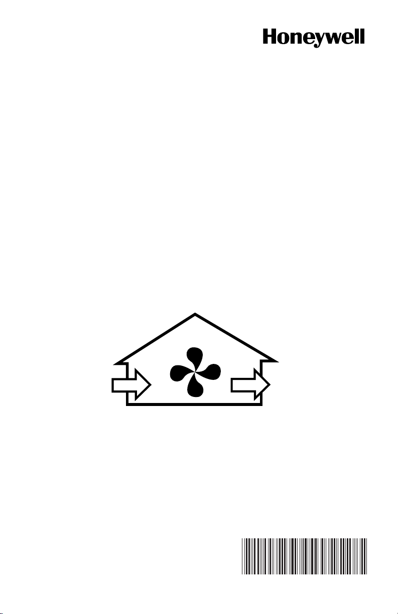
The Honeywell Perfect Window™ Fresh Air Ventilation System removes stale,
unhealthy air and replaces it with a stream of fresh air. Its powerful centrifugal blowers
bring fresh air into your home and at the same time, exhaust stale air in an equal
amount. Both incoming and outgoing airstreams pass through either a heat transfer core
or an energy transfer core where the heat only or the heat and the moisture from the
exhaust air are efficiently transferred to the incoming fresh air. An air duct system
supplies the fresh air brought in by the Perfect Window™ ventilator and distributes it
throughout your home. Another duct draws the existing stale, air back to the Perfect
Window™ ventilator and then exhausts it outdoors.
It’s really very simple...and remarkably effective!
The Perfect Window
™ Fresh Air Ventilation System
consists of:
1. Air Circulation FAN and Motor
Inside the casing are two fans, one for exhaust and one for fresh air supply. The
electric motor that operates the fan is 1/15 hp to 1/20 hp (depending on the ventilator model) and uses the same amount of power as a 100 watt light bulb.
2. Air Filters
There are two permanent washable air filters in your ventilator. The filters lower
the amount of dust and outside particulates entering the ventilator core and your
fresh air supply.
3 69-1188—03
Page 4
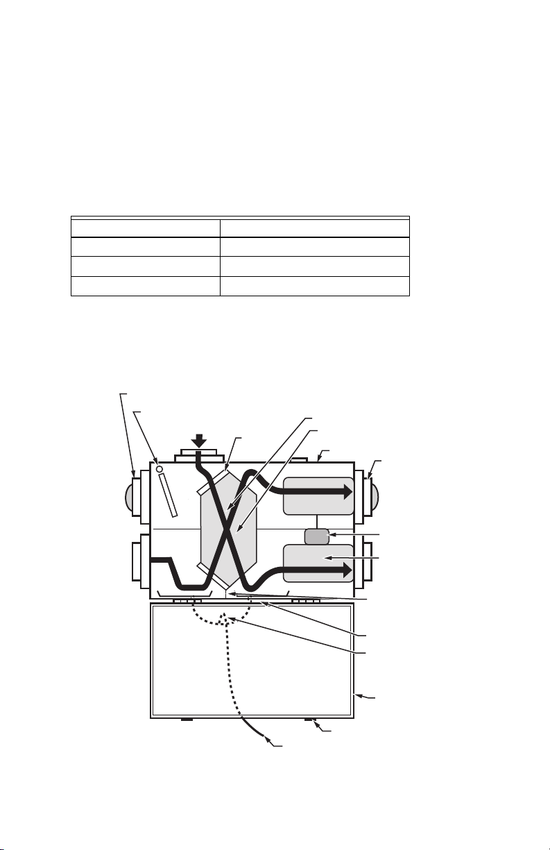
3.
Condensate Tray and Drain (Some Models)
Condensation normally forms on the energy transfer core during the cold weather
(below 27°F or -3°C). Moisture can build up when the warm air from your home
comes in contact with the cold air from outside. The tray collects the moisture and
funnels it to the drain. The drain pans are made of thermoformed plastic for easy
cleaning.
4. Defrost Mechanism (Some Models)
Some models have an electronically-controlled damper frost control mechanism
to prevent frost buildup on the core. Defrost timing will change based on incoming outdoor air temperature.
Outdoor Temperature Defrost Timer
27°F (-3°C) 3 minute defrost/25 minute run
-4°F (-20°C) 4.5 minute defrost/17 minute run
-31°F (-35°C) 7 minute defrost/15 minute run
Example: When the outside temperature drops below
27°F (-3°C)
timer is activated. At the end of the 25-minute run cycle, when the core can
experience some nominal frost buildup, the timer activates a motor-driven
damper door that simultaneously opens the defrost port and closes off the
supply air port.
.
DEFROST PORT (NON-DUCTED)
DEFROST DAMPER
(MOTOR AND DOOR)
FILTERS
(2)
CORE INSTRUCTIONS
ENERGY TRANSFER
CORE
CABINET
DRAIN
LINE
DOOR
KEEPER
PLATE (2)
DUCTING
(4 PORTS)
MAIN
MOTOR
SQUIRREL
CAGE FAN
CORE GUIDE
CHANNEL (4)
DRAIN PANS
DRAIN
P TRAP
INSULATED
ACCESS
DOOR
M29852
the defrost
69-1188—03 4
Page 5

5a. Energy Transfer Core
As the exhaust and fresh air pass through opposite sides of the Energy Transfer
Core, heat is transferred from the warm side to the cold side. This heat transfer
reduces the cost of conditioning the fresh outside air that is brought into your
home. This increases the temperature of the fresh air brought inside in the winter
and cools the fresh air brought inside in the summer. In addition, for ER150 and
ER200 models, moisture is transferred from the wet side to the dryer side. The
core removes easily for cleaning.
5b. Heat Transfer Core
As the exhaust and fresh air pass through opposite sides of the Heat Transfer
Core heat is transferred from the warm side to the cold side. This heat transfer
reduces the cost of conditioning the fresh outside air that is brought into your
home. This increases the temperature of the fresh air brought inside in the winter
and cools the fresh air brought inside in the summer. The core removes easily
for cleaning.
Operating your Fresh Air Ventilation System
Changing Fan Speed
Depending on the control installed with your ERV, you might be able to change the fan
speed. Check the manual of your control for more information.
Connecting a Remote Device
Your ventilator comes equipped with a low voltage terminal strip for connection to
several optional control devices.
EXTERNAL REMOTE WALL CONTROL
(DEHUMIDISTAT)
The dehumidistat (connected to your ventilator) is designed to control the operation of
the ventilator fan to help keep the humidity level in your home comfortable. If an
independent humidifier is installed and set at 30% (a normal indoor winter level) then the
dehumidistat (for the ventilator) should be set at least 10% higher, in this case 40%. With
the ventilator operating on low speed and no one at home to produce humidity, the
humidifier will keep the humidity level at its setpoint. If the humidity levels rise (due to
occupant activity) above the 40% level, then the dehumidistat will automatically increase
the speed of the ventilator fan to high until the humidity level falls below 40%.
NOTE: During the winter months, the air inside your home usually contains more
TIMER
For your convenience, Honeywell provides an optional timer control that can fit a wide
variety of needs, for example, exhaust humid air from the bathroom or kitchen (see the
timer instructions for selection and part numbers).
moisture than the outside air even though the outside relative humidity is
higher than the inside relative humidity. The ventilator will automatically turn
off the dehumidistat feature during the summer months when the outside air
contains more moisture than the inside air.
5 69-1188—03
Page 6

WALL SWITCH
WARNING
A wall switch can also be used to switch your ventilator fan speed to high. The fan will
run at high speed until the wall switch is turned off.
The remote device can be wired to run the ventilator at either the high or low speed.
Getting the most from your Fresh Air Ventilation System
HOW MUCH VENTILATION DO I NEED?
During the seasons that your windows and doors are closed (winter and summer if you
have air conditioning), the ventilator should operate continuously when the home is
occupied, and either continuously or intermittently when not occupied.
For most installations, the ventilator will normally be set to operate continuously on low
speed with the option of going to high speed as the need arises. For example, if you
are entertaining and there is a large number of people present (some may be
smoking), the ventilator should be switched to high speed.
YOUR VENTILATOR MAY BE SET TO HIGH SPEED:
if the system includes an optional remote control, switch it to the ON position.
NOTE: To set an optional dehumidistat, refer to the previous section of this booklet.
To operate other remote devices, refer to the device owner’s manual.
Maintenance Instructions for your Fresh Air Ventilation System
Electrical Shock Hazard.
Can cause personal injury or equipment damage.
Disconnect power supply before performing maintenance.
The Perfect Window™ Fresh Air Ventilation System must be maintained on a regular
basis for best efficiency. Honeywell recommends that the ventilator be cleaned and
checked at least twice a year, preferably at the beginning of each heating and cooling
season.
Check and Clean
EXTERIOR HOODS
Exterior hoods should be inspected at least once a month. Be sure exhaust and fresh
air supply hoods are not blocked up or restricted by leaves, grass or snow. In winter, it
is especially important to make sure snow is not blocking the hoods or that frost has
not built up on the wire mesh (bird screen).
69-1188—03 6
Page 7

WARNING
FILTER CLIP
FILTER
CORE GUIDE
CHANNEL
M29786
Carbon Monoxide Hazard.
Can cause personal injury or equipment damage.
Hood blockage can cause a change of pressure in building which can lead to
possible spillage from combustible appliances.
CLEANING FILTERS AND CORE
Air filters should be cleaned twice a year. The standard filters supplied with your
ventilator are removable and washable. Core should be cleaned twice each year.
1. Open ventilator door by loosening draw latches on top of unit and swinging door
open. For easier access, remove door by moving it right to disengage hinges.
2. Carefully grip ends of core, (be careful not to damage the aluminum fins); then
pull evenly outward. Core fits tightly, but slides out of channels.
3. Once core is removed, filters can be removed by detaching the clips holding
them in place. Note clip installation for reassembly.
4a. ERV core: Vacuum the ERV core or rinse with cold water. Do not use soap, dish-
washer, or a pressure washer.
4b. HRV core: Soak and rinse the HRV core in warm soapy water. Do not use clean-
ing solutions.
5. Wash the filters in warm soapy water.
6. Place the clean filter (wet or dry) over the core and secure it in place with the
clips.
7. Reinstall core by sliding it into the four corner channels. (Water cannot damage
gasket and label on core ends, so it is not necessary to remove them from the
core.).
NOTE: The core is designed to appear to protrude from the cabinet approximately
1/8 in. (3mm) so the access door fits tightly against the core.
7 69-1188—03
Page 8

DRAIN LINE (SOME MODELS)
Clean the drain line once a year.
1. Inspect the drain line, drain spout and P trap for blockage, mold or kinks.
2. Flush with warm soapy water and replace if worn or bent, or if it can not be
cleaned.
DEFROST PORT (NON-DUCTED)
DEFROST DAMPER
(MOTOR AND DOOR)
FILTERS
(2)
CORE INSTRUCTIONS
ENERGY TRANSFER
CORE
CABINET
DUCTING
(4 PORTS)
MAIN
MOTOR
SQUIRREL
CAGE FAN
CORE GUIDE
CHANNEL (4)
DRAIN PANS
DRAIN
P TRAP
INSULATED
ACCESS
DOOR
M29852
DRAIN
LINE
DOOR
KEEPER
PLATE (2)
GENERAL MAINTENANCE
Twice a year, wipe the inside of the cabinet with a damp cloth to remove dirt, bugs and
debris that can be present.
FANS
If the fans accumulate dirt, it could cause an imbalance and excessive vibration of the
ventilator. A reduction in air flow can also occur. In a newly constructed house, this
often happens within the first year due to heavy dust residue in the entire system. It
can also occur periodically, depending on the outdoor conditions. If you suspect that
service is required, please contact the ventilator installer or your local HVAC
contractor.
69-1188—03 8
Page 9

Troubleshooting
Lack of power to the ventilator:
• Power failure of electrical box.
• Loose or unplugged power cord.
• Faulty breaker or fuse in home’s electrical panel.
• Call your installation contractor.
Power to the ventilator, but no fan operation:
• Ventilator is in standby mode and optional remote dehumidistat is set to OFF or the
humidity setting is higher than room humidity.
• Door is not closed properly, the safety interlock switch will keep the ventilator off.
Check that the access door is firmly closed and latched.
• Refer to operating instructions.
• Call your installation contractor for service.
9 69-1188—03
Page 10

Limited Warranty
Honeywell warrants this product, to be free from defects in the workmanship or materials, under
normal use and service, for a period of one (1) year from the date of purchase by the consumer.
If, at any time during the warranty period, the product is defective or malfunctions, Honeywell
shall repair or replace it (at Honeywell’s option) within a reasonable period of time.
If the product is defective
(i)return it, with a bill of sale or other dated proof of purchase, to the retailer from which you
purchased it, or
(ii)package it carefully, along with proof of purchase (including date of purchase) and a short
description of the malfunction, and mail it, postage prepaid, to the following address:
Honeywell Return Goods
Dock 4, MN10-3860
1985 Douglas Drive North
Golden Valley, MN 55422
This warranty does not cover removal or reinstallation costs. This warranty shall not apply if it is
shown by Honeywell that the defect or malfunction was caused by damage which occurred while
the product was in the possession of a consumer.
Honeywell’s sole responsibility shall be to repair or replace the product within the terms stated
above. HONEYWELL SHALL NOT BE LIABLE FOR ANY LOSS OR DAMAGE OF ANY KIND,
INCLUDING ANY INCIDENTAL OR CONSEQUENTIAL DAMAGES RESULTING, DIRECTLY OR
INDIRECTLY, FROM ANY BREACH OF ANY WARRANTY, EXPRESS OR IMPLIED, OR ANY
OTHER FAILURE OF THIS PRODUCT. Some states do not allow the exclusion or limitation of
incidental or consequential damages, so this limitation may not apply to you.
THIS WARRANTY IS THE ONLY EXPRESS WARRANTY HONEYWELL MAKES ON THIS
PRODUCT. THE DURATION OF ANY IMPLIED WARRANTIES, INCLUDING THE
WARRANTIES OF MERCHANTABILITY AND FITNESS FOR A PARTICULAR PURPOSE, IS
HEREBY LIMITED TO THE ONE YEAR DURATION OF THIS WARRANTY. Some states do not
allow limitations on how long an implied warranty lasts, so the above limitation may not apply to
you.
This warranty gives you specific legal rights, and you may have other rights which vary from state
to state.
If you have any questions concerning this warranty, please write Honeywell Customer Relations,
1985 Douglas Dr N, MN10-1461, Golden Valley, MN 55422. In Canada, write Honeywell Limited/
Honeywell Limitée, 35 Dynamic Dr, ON15, Toronto Ontario M1V 4Z9.
69-1188—03 10
Page 11

11 69-1188—03
Page 12

Automation and Control Solutions
Honeywell International Inc.
1985 Douglas Drive North
Golden Valley, MN 55422
Honeywell Limited-Honeywell Limitée
35 Dynamic Drive
Toronto, Ontario M1V 4Z9
yourhome.honeywell.com
® U.S. Registered Trademark
© 2010 Honeywell International Inc.
69-1188—03 M.S. Rev. 01-10
Printed in U.S.A.
 Loading...