

Page 1
M29857
68-0171EF-01
HR150, 200; ER150, 200 Perfect Window™
Fresh Air Ventilation Systems
PRODUCT DATA
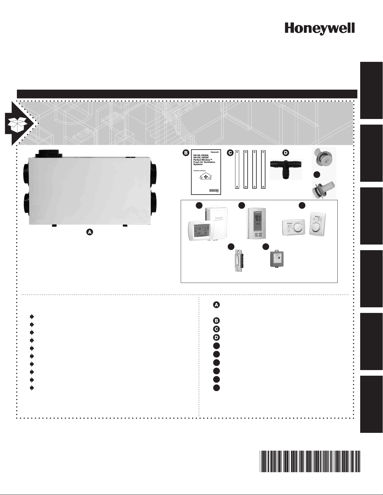
Included In thIs VentIlatIon system Box
*
e
STARTED
GETTING
MOUNTING PLUMBING WIRING APPENDICESDUCTING
*
Tools and accessories needed to install Perfect
Window™ Fresh Air Ventilation Systems
Wire cutter/stripper
18-gauge wire (up to 5 conductor)
Standard screwdriver
Insulated 6-inch round duct
Non-insulated 6-inch round duct
Two 6-inch weather hoods
Two 6-inch starter collars
1/2-inch I.D. drain hose
Airflow balancing kit
Foil tape
F1 F3
OPTIONAL CONTROLS SOLD SEPARATELY
e
F1
F2
F3
F4
F5
F2
F4 F5
HR150/200 or ER150/200 Perfect
Window™ Fresh Air Ventilation System
Owner’s Manual
Hanging straps
* T-fitting
* 2 drain spouts
VisionPRO IAQ control
TrueIAQ
Dehumidistat H8908
Digital fan timer
W8150 ventilation control
Not with “C” models.
*
Page 2

Page 3

Perfect Window Fresh Air Ventilation Systems
GETTING STARTED
Safety Definitions and Precautions . . . . . . . . . . . . . . 2
Application ................................. 3
Features .................................. 3
Planning the Installation . . . . . . . . . . . . . . . . . . . . . . 4
Sizing .................................. 5
Mounting Position and Location. . . . . . . . . . . . . . . . . 6
Balancing Airflow ............................ 9
MOUNTING
Installation ................................ 10
Suspended from Floor Joists ..................10
PLUMBING
Installing Drain Line and P-Trap . . . . . . . . . . . . . . . 11
STARTED
GETTING
MOUNTING PLUMBING WIRING APPENDICESDUCTING
WIRING
Heat Recovery Ventilator (HRV) and
Energy Recovery Ventilator (ERV) Connections . . . 12
Digital Fan Timer . . . . . . . . . . . . . . . . . . . . . . . . . . . 12
DUCTING
Airflow Balancing ........................... 16
Balancing Procedure ........................ 16
APPENDICES
Startup and Checkout . . . . . . . . . . . . . . . . . . . . . . . 17
Cleaning Filters and Core .................. 17
Inspecting Exterior Hoods . . . . . . . . . . . . . . . . . 17
Troublshooting ............................. 18
Parts List ................................. 20
Specifications . . . . . . . . . . . . . . . . . . . . . . . . . . . . . 22
NEED HELP? For assistance with this product please visit http://yourhome.honeywell.com
?
or call Honeywell Customer Care toll-free at 1-800-468-1502.
Read and save these instructions.
® U.S. Registered Trademark. Patents pending. Copyright © 2010 Honeywell International Inc. All rights reserved.
HR150, 200; ER150, 200 Perfect Window™ Fresh Air Ventilation Systems 68-0171EF—01
1
Page 4

GETTING
STARTED
Safety Definitions and Precautions
Safety Definitions
These safety terms identify information you must read.
CAUTION: Indicates a hazardous situation which, if not avoided, could cause bodily injury
or property damage.
WARNING: Indicates a hazardous situation which, if not avoided, could result in death or serious injury.
Safety Precautions
Make sure you read and understand the following safety and/or property hazards before installing,
using, or working with the Perfect Window™ Fresh Air Ventilation System:
All ducting to the outdoors must be terminated above anticipated snow lines and be fitted with a •
weather cap that incorporates bird screening.
CAUTION: Electrical shock hazard.
Can cause personal injury or equipment damage.
Disconnect power supply to prevent electrical shock or equipment damage.
CAUTION: Electrical Shock Hazard.
Can cause personal injury.
Be sure ventilator is correctly grounded. Confirm polarity of power line switched with safety (disconnect)
switch when cleaning or servicing unit.
CAUTION: Electrical Hazard.
Can cause equipment damage
Disconnect HRV/ERV from power source before connecting or disconnecting digital fan timer or other
device to HRV/ERV high-speed override terminals.
2
HR150, 200; ER150, 200 Perfect Window™ Fresh Air Ventilation Systems 68-0171EF—01
Page 5

Application
The HR150B and HR200B Perfect Window™ Fresh Air Ventilation Systems provide proper levels of ventilation
with energy savings by transferring heat between the exhaust and fresh air streams.
The ER150B and ER200B Perfect Window™ Fresh Air Ventilation Systems provide proper levels of ventilation
with energy savings by transferring heat and moisture between the exhaust and fresh air streams.
The ER150C and ER200C Perfect Window™ Fresh Air Ventilation Systems are specifically designed for
installations in unconditioned spaces such as attics and garages in regions where the outdoor temperature does
not drop below freezing.
Features
Remotely control two-speed fan.•
Integral balancing dampers for quick installation.•
Provides ventilation that helps contractors meet ASHRAE 62.•
Automatic, economical built-in frost control available for operation to design temperatures of -40°F (-40°C).•
HR150 and HR200 models have an easy-to-clean aluminum cross-flow core.•
ER150 and ER200 models have an advanced energy heat and moisture recovery fixed core.•
Washable energy transfer core.•
Includes vibration isolation hardware and duct collars.•
Insulated cabinet made of rugged steel.•
Permanent (washable) prefilters.•
Quiet operation.•
Digital fan timer option on all models.•
Advanced ventilation algorithms available on VisionPRO IAQ, TrueIAQ and W8150 controls.•
Interlock the ERV/HRV to an air handler or furnace blower.•
Dehumidistat operation deactivated in summer.•
STARTED
GETTING
HR150, 200; ER150, 200 Perfect Window™ Fresh Air Ventilation Systems 68-0171EF—01
3
Page 6
GETTING
STALE
AIR FROM
INSIDE
DEFROST
PORT
FRESH
AIR TO
INSIDE
FRESH AIR
FROM OUTSIDE
STALE
AIR TO
OUTSIDE
M29739
BALANCING DAMPER
FILTERS
FILTERS (2)
DRAIN
M29853
MOTOR
BLOWERS
FRESH AIR
FROM OUTSIDE
DEFROST
PORT
DRAIN PANS
BALANCING
DAMPER
BALANCING
DAMPER
CORE
STALE
AIR FROM
INSIDE
FRESH
AIR TO
INSIDE
STALE
AIR TO
OUTSIDE
FRESH
AIR TO
INSIDE
FRESH AIR
FROM OUTSIDE
M29861
MOTOR
MOTOR
STALE AIR
FROM HOUSE
ENERGY
TRANSFER
CORE
BALANCING
DAMPER
CORE
STALE AIR
TO OUTSIDE
BALANCING
DAMPER
FILTERS (2)
STARTED
Planning the Installation
Failure to comply with these requirements will result in voided warranty, improper installation, and
service callbacks.
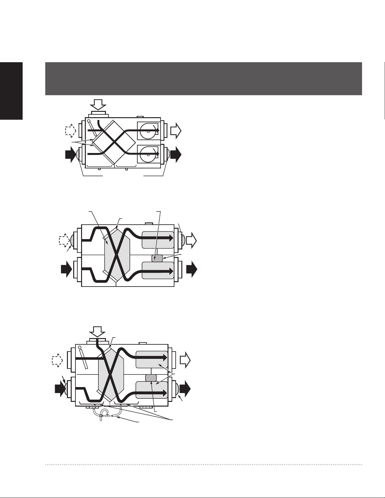
The Fresh Air Ventilation System is designed to
supply fresh air and exhaust stale air. The system
draws fresh outdoor air through the ventilator for
distribution throughout the house.
Heat Recovery Ventilator
Stale air is exhausted through the ventilator and to
the outdoors. Heat is transferred from one airstream
to the other as the air passes through the opposite
Duct connections and airflow (HR150B/HR200B).Fig. 1.
sides of the heat transfer core. See Fig. 1.
Energy Recovery Ventilator
Stale air is exhausted through the ventilator and to
the outdoors. Heat and moisture is transferred from
one airstream to the other as the air passes through
the opposite sides of the energy transfer core.
See Fig. 2 and 3.
4
Duct connections and airflow (ER150C/ER200C).Fig. 2.
Duct connections and airflow (ER150B/ER200B).Fig. 3.
HR150, 200; ER150, 200 Perfect Window™ Fresh Air Ventilation Systems 68-0171EF—01
Page 7

Sizing
ASHRAE 62.2
There are several methods that can provide
satisfactory results for sizing a ventilator to provide
adequate ventilation for a home. There is a new
residential ventilation standard, ASHRAE 62.2, that
suggests the following:
7.5 CFM per person (count people as 1 per •
bedroom plus 1) plus 1 CFM per 100 sq. ft.
Example:
2200 sq. ft. house with 4 bedrooms
= (7.5 CFM x (4 bedrooms + 1)) + (1 CFM x (2200 sq. ft. / 100))
= (7.5 x 5) + (2200 / 100)
= 37.5 + 22
= 59.5 CFM
In this case 60 CFM continuous would provide
satisfactory ventilation for this home.
ASHRAE 62.1
Some regions still use the previous standard, ASHRAE
62.1, as the code for ventilation in their region.
The ASHRAE Standard 62.1 Ventilation for Acceptable
Indoor Air Quality suggests the following:
Option 1: Fresh Air Ventilation System provides
continuous fresh air supply of 93 cfm, and intermittent
capacity for bathrooms of 150 cfm. A separate 100
cfm exhaust fan is used for the range hood.
Supply air flow required = 93 cfm
Exhaust air flow required = 150 cfm
Any Honeywell ventilation unit provides suitable
ventilation capacity. See Fig. 22.
Option 2: Fresh Air Ventilation System provides
continuous 93 cfm fresh air supply, 150 cfm
intermittent exhaust capacity for bathrooms and
continuous 50 cfm kitchen ventilation.
Supply air flow required = 93 cfm
Exhaust air flow required = 200 cfm
Honeywell HR200/ER200 have the exhaust capacity
required to meet the ventilation needs of this
application. See Fig. 22.
STARTED
GETTING
.35 air changes per hour (ach) but not less than 15 •
cfm per person for living areas = house size (sq ft)
x ceiling height (ft) / 60 (min) x.35 (ach)
Example:
= 2000 sq ft x 8 ft / 60 min x .35 ach = 93 cfm
50 cfm intermittent or 20 cfm continuous capacity •
for bathrooms
Example:
50 cfm intermittent x 3 bathrooms = 150 cfm
20 cfm continuous x 3 bathrooms = 60 cfm
100 cfm intermittent or 25 cfm continuous capacity •
for kitchens
Example:
100 cfm intermittent x 1 kitchen = 100 cfm
25 cfm continuous x 1 kitchen = 25 cfm
HR150, 200; ER150, 200 Perfect Window™ Fresh Air Ventilation Systems 68-0171EF—01
5
Page 8
GETTING
INSULATED
FLEX DUCT
COLLAR ON
VENTILATOR
SEAL INTERIOR LINING OF
FLEX DUCT TO INSIDE COLLAR
SEAL OUTER LINING OF FLEX
DUCT TO OUTER COLLAR
M6557
STARTED
Mounting Position and Location
The HR150/ER150 and HR200/ER200 can be
suspended from exposed ceiling joists, ceiling surface
or floor mounted. (Level ventilator so drains function
correctly.)
NOTE: ER150C and ER200C are specifically designed
for installations in unconditioned spaces such as
attics and garages in regions where the outdoor
temperature does not drop below freezing. (These
units are not equipped with drain kits.)
Locate fresh air intake 6 ft (2m) or more from stale •
air exhaust to prevent exhaust air from re-entering.
Locate ventilator where length of ducting required •
is minimal.
Install HR150/ER150 and HR200/ER200 in a
conditioned space using these guidelines:
Pipe drain line (ER150C and ER200C do not have •
drain kits) from the ventilator to a drain.
Use an existing electrical outlet with appropriate •
current rating (or install one) close to ventilator
power cord.
Allow space for drain line by placing the ventilator •
at least 10 in. (254 mm) off the floor.
For access and removal of ventilator core, allow at •
least 25 in. (635 mm) of open space in front of unit.
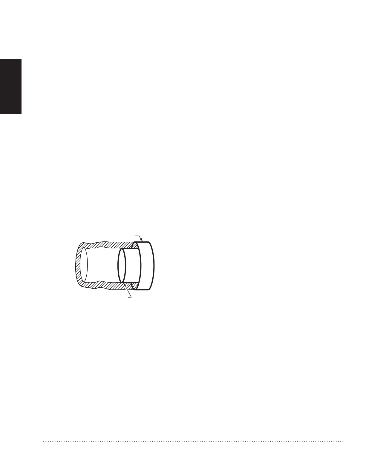
Ducting
Ducting between the ventilator and the outdoors must
be insulated and have a continuous air vapor barrier.
See Fig. 4.
IMPORTANT
All ducting to the outdoors must be terminated above
anticipated snow lines and be fitted with a weather cap
that incorporates bird screening.
Sealing insulated duct terminations.Fig. 4.
6
HR150, 200; ER150, 200 Perfect Window™ Fresh Air Ventilation Systems 68-0171EF—01
Page 9

Design and installation of ductwork must be according to standard HVAC practice to deliver required quantities
COLD AIR
RETURN
EXHAUST AIR FROM
VARIOUS PARTS OF
HOME (BATHROOMS
IF REQUIRED; KITCHENS
IF REQUIRED; ROOMS
WITHOUT OPERABLE WINDOWS,
A
ND POTENTIALLY BASEMENTS).
FORCED AIR
FURNACE
COMBUSTION
OR ELECTRIC
M6549D
RETURN
AIR
OUTDOORS
NOTES:
1.
2.
3.
4.
FURNACE BLOWER NEED NOT OPERATE TO PROVIDE GOOD AIR DISTRIBUTION/QUALITY WITH THIS SYSTEM.
IF FURNACE BLOWER OPERATION IS REQUIRED TO HELP DISTRIBUTE SUPPLY AIR: RUN CONTINUOUSLY
OR INTERLINK ELECTRICALLY (LOW VOLTAGE).
NO SEPARATION REQUIREMENTS ARE NECESSARY BETWEEN DIRECT CONNECTION POINT AND FURNACE.
WEATHER-HOOD ARRANGEMENT IS FOR DRAWING ONLY. 6 FT (2m) MINIMUM SEPARATION REQUIRED,
18 IN. (0.46m) ABOVE GRADE MINIMUM.
of fresh air to temperature-controlled space and exhaust equivalent quantities of room air to the outside.
Keep intake and exhaust duct runs as short as possible with few bends or elbows.
Keep duct sizes as large as possible throughout the installation.•
Use a 6 in. diameter round duct for all connections to and from the ventilator.•
Separate outside intake and exhaust vents by at least 6 ft (2m).•
NOTES: Do not locate the fresh air vent where it blows directly onto occupants or the thermostat.
Do not locate the fresh air intake close to known sources of pollutants such as automobile exhaust, a
dryer vent or chimney smoke.
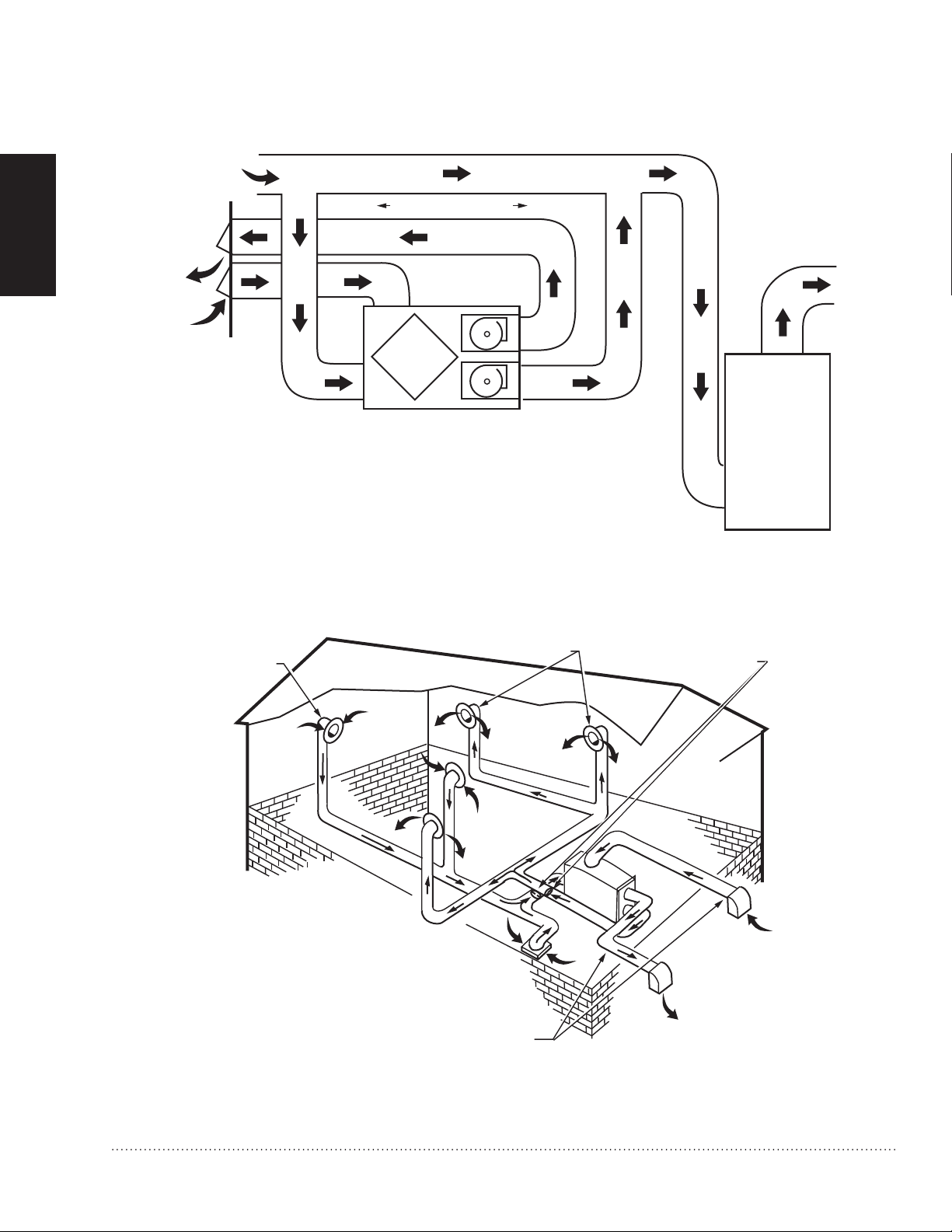
Ducting the supply outlet and/or the exhaust inlet of the ventilator to the return air plenum of the air handler •
is an excellent way to distribute fresh air and exhaust stale air from all parts of the house, while reducing
installation costs. When choosing this method, balance the ventilator when the air handler is running and
interlock the ventilator so that it can run only when the air handler runs. See Fig. 6. An alternate method is to
balance the ventilator when the air handler is not running and let the ventilator run whether the air handler is
running or not, see Fig. 5. An independent installation is shown in Fig. 7.
NOTE: When the home is occupied, continuous operation of the ventilator is recommended. When the furnace air handler
operates, fresh air is distributed through the heating/air conditioning supply registers. When the air handler is off,
fresh air is delivered through both supplies and returns.
STARTED
GETTING
An electrical interlock or an automatically powered damper must be used to prevent unwanted entry of •
outside air if the ventilator is turned off while the furnace air handler continues to operate.
HR150, 200; ER150, 200 Perfect Window™ Fresh Air Ventilation Systems 68-0171EF—01
Direct connection of supply air stream to furnace cold air return for HRV/ERV.Fig. 5.
7
Page 10
GETTING
40 IN. (1m) MINIMUM
COLD AIR
RETURN
FORCED AIR
FURNACE
COMBUSTION
OR ELECTRIC
M6548E
RETURN
AIR
OUTDOORS
NOTES:
1.
2.
3.
4.
FURNACE BLOWER IS REQUIRED TO OPERATE WHEN VENTILATION IS REQUIRED.
SET THE FURNACE BLOWER TO RUN CONTINUOUSLY, OR INTERLINK ELECTRICALLY
(LOW VOLTAGE).
MINIMUM SEPARATION OF 40 IN. IS REQUIRED BETWEEN THE TWO
DIRECT CONNECTIONS.
EXHAUST AIR CONNECTION SHOULD BE UPSTREAM OF THE SUPPLY
AIR CONNECTION TO PREVENT EXHAUSTING ANY FRESH AIR.
WEATHER-HOOD ARRANGEMENT IS FOR DRAWING ONLY. 6 FT. (2 m)
MINIMUM SEPARATION REQUIRED, 18 IN. (0.46m) ABOVE GRADE MINIMUM.
ADJUSTABLE FRESH
AIR SUPPLY
ADJUSTABLE DAMPERS FOR
BALANCING AIR FLOW INTO
AND OUT OF THE HOUSE
FRESH AIR
SUPPLY HOOD
STALE AIR
EXHAUST HOOD
FLEXIBLE INSULATED DUCTING
WITH A VAPOR BARRIER
VENTILATOR EXHAUSTS FROM KITCHEN AND/OR
BATHROOMS OR OTHER CENTRAL LOCATIONS
TO OUTDOORS.
VENTILATOR SUPPLIES OUTDOOR AIR DIRECTLY TO
EACH BEDROOM, TO EACH FLOOR WITHOUT A
BEDROOM, AND TO THE PRINCIPAL LIVING AREAS.
ADJUSTABLE
STALE AIR
RETURN
M4911A
NOTES:
1.
2.
STARTED
Direct connection of ventilator supply air stream and exhaust air stream to furnace cold air return.Fig. 6.
8
HR150, 200; ER150, 200 Perfect Window™ Fresh Air Ventilation Systems 68-0171EF—01
Independent ventilator installation.Fig. 7.
Page 11

Balancing Airflow
Balancing the airflow verifies that the Fresh Air
Ventilation System is delivering the intended airflow
and energy performance. Use the Airflow Balancing
instructions in the Installation section to check and
balance the airflow.
Controls
Remote Override Switch Functions On/Off Control
If continuous ventilation is not required, an on/off
control can be used to activate the ventilator when it is
switched to Standby. Controls that can be used for this
function include dehumidistats, timers, wall switches
and the ventilate function of the VisionPRO IAQ and
TrueIAQ digital controls.
Dehumidistat
If moisture control in bathrooms is a primary function
of the system, a dehumidistat can be used to switch
the ventilator from a Low or Standby setting to the High
setting. Moisture removal throughout the entire home
can only be achieved when the outside air contains
less moisture than the inside air (typically during cold
weather conditions).
An HRV will override a call from the dehumidistat if
the outdoor temperatures exceed 60°F (15.6°C) for
a 24-hour period. The dehumidistat function will be
re-enabled if the unit is unplugged for 3 minutes or if
the outdoor temperature drops below 60°F (15.6°C)
for a 24-hour period. The dehumidistat function is
permanently enabled in ERVs.
IAQ Controls
The VisionPRO IAQ and TrueIAQ controls can
automatically control the ventilator by pressing the
Ventilate button on the control. See the control owner’s
guide for complete instructions.
Moisture Control
When a building is new, there is excess moisture in
the wood, plaster, cement and other construction
materials. When the new building is occupied, the
activities of the occupants also increase the moisture
level. There can also be high levels of formaldehyde
and other chemicals that were used in the building
materials. Running the ventilation system on high
speed provides optimum indoor air pollutant reduction.
High speed also provides maximum moisture removal
when the outside air contains less moisture than the
inside air. (Typically during cold weather conditions.)
Operating Damper Frost Control
Some models have an electronically-controlled damper
frost control mechanism to prevent frost buildup on the
core. Defrost timing will change based on incoming
outdoor air temperature.
Outdoor Temperauture Defrost Timer*
27 °F (-3 °C) 3 minute defrost/25 minute run
-4 °F (-20 °C) 4.5 minute defrost/17 minute run
-31 °F (-35 °C) 7 minute defrost/15 minute run
* The R2000 jumper on the control board can be
removed to meet R2000 program requirements.
Example:
When the outside temperature drops below 27 °F
(-3 °C), the defrost timer is activated. At the end of the
25 minute run cycle, when the core can experience
some nominal frost buildup, the timer activates a
motor-driven damper door that simultaneously opens
the defrost port and closes off the supply air port.
STARTED
GETTING
Digital Fan Timer
The ventilator controls are compatible with the Digital
Fan Timer. If more than one timer is activated, each
runs independently with the ventilator running at high
speed until all timers have timed out. Up to eight timers
can be installed in a system.
HR150, 200; ER150, 200 Perfect Window™ Fresh Air Ventilation Systems 68-0171EF—01
9
Page 12

INSTALLATION
When Installing this Product…
1. Read these instructions carefully. Failure to follow these instructions could damage the product or cause a
hazardous condition.
2. Check the ratings on the product to make sure the product is suitable for your application.
3. Installer must be a trained, experienced service technician.
4. After installation is complete, check out product operation as provided in these instructions.
CAUTION: Electrical Shock Hazard.
Can cause personal injury or equipment damage.
Disconnect power supply to prevent electrical shock or equipment damage.
MOUNTING
Unpacking Fresh Air Ventilation System
Check that all the components are included. The Fresh Air Ventilation System is shipped assembled. The carton
contains the following:
Fresh Air Ventilation System.•
Vibration isolation straps (4).•
Drain fittings (2) and T fitting (1).•
Literature package.•
Except for the mounting hardware and drain fittings, the ventilator is ready for installation. Wiring, drain
connections and ducting are required to complete the installation.
Mounting
Suspended from Floor Joists
Mount the four vibration isolation straps (provided) to the side of the ventilator using the mounting screws located on the 1.
cabinet. See Fig. 23.
Securely fasten the other ends of the straps to the floor joists with wide-head nails (not supplied), making sure the unit 2.
is level. The straps are designed to reduce noise, resonance or harmonics; therefore, using the full length of the strap
between the ventilator and the floor joists is recommended.
NOTE: Removing door and core reduces the weight of the ventilator, making it easier to lift into place.
10
HR150, 200; ER150, 200 Perfect Window™ Fresh Air Ventilation Systems 68-0171EF—01
Page 13

Installing Drain Line and P-Trap
M6552
DRAIN
PAN
O RING
HR
BOTTOM
WASHER
NUT
TO DRAIN
T FITTING
TAPE
M6551
Installing drain line.Fig. 8.
Installing P-trap.Fig. 9.
There are two holes at the bottom of the ventilator for
the drain pan connectors.
Insert the connectors through the hole in the drain pan 1.
and the bottom of the unit.
Place the washer and nut on the connector.2.
Hand tighten the nut. See Fig. 8.3.
Construct a P-trap using the plastic T-fitting provided.
Cut two lengths of 1/2 in. ID hose and connect each 1.
drain fitting to the end of the T-fitting.
Position the center leg of the T-fitting so it points upward.2.
Connect the drain line to the center leg and tape it in 3.
place to prevent any kinks. See Fig. 9.
This creates a trap that will hold some condensation
and prevent odors from being drawn up through the
drain hose into the unit. If the unit is installed during a
season when it is unlikely that condensation will form,
fill the trap with tap water.
PLUMBING
HR150, 200; ER150, 200 Perfect Window™ Fresh Air Ventilation Systems 68-0171EF—01
11
Page 14
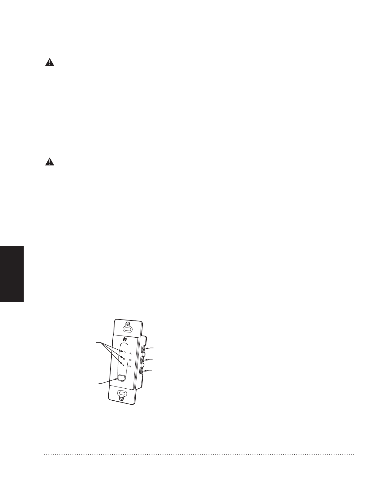
WIRING
M29806
HIGH SPEED
STATUS LIGHTS
SELECT BUTTON
INITIATES HIGH
SPEED VENTILATION
FOR 20, 40 OR 60
MINUTES
YELLOW
RED
GREEN
CAUTION: Electrical shock hazard.
Can cause personal injury.
Be sure ventilator is correctly grounded. Confirm polarity of power line switched with safety (disconnect)
switch when cleaning or servicing unit.
IMPORTANT
The hot line (black) is the correct line to switch. See Fig. 19. To confirm correct polarity, use voltmeter or test lamp to
verify there is no power after the switch when the door is open. Check between that point and ground (on cabinet). This
process must be used because occasionally some dwellings are incorrectly wired.
CAUTION: Electrical hazard.
Can cause equipment damage.
Disconnect HRV/ERV from power source before connecting or disconnecting digital fan timer or other
device to HRV/ERV high-speed override terminals.
WIRING
IMPORTANT
Do not connect external power sources to the highspeed override terminals.
Heat Recovery Ventilator (HRV) and Energy Recovery Ventilator (ERV) Connections
The connector is a three-prong, 120 Vac plug with ground. If further wiring is required, Honeywell recommends
that a licensed electrician make all electrical connections. It is very important that the unit be correctly grounded.
Digital Fan Timer
Mount digital fan timer in a full or one-half depth
electrical box in the living space. See Fig 10.
Press and release the Select Button to activate high
speed on the ventilator. Change between 20-, 40-, and
60-minute override times by pressing and releasing
the Select Button.
The status light will dim after 10 seconds of run time.
The status light will flash during the last 5 minutes of
override. All timers connected to the unit will illuminate
for the duration of the override.
Set the lockout mode by holding the Select Button for
5 seconds. Unlock by holding for 5 seconds.
12
Digital fan timer lights and Select Button.Fig. 10.
HR150, 200; ER150, 200 Perfect Window™ Fresh Air Ventilation Systems 68-0171EF—01
Page 15
1
2
3
4
5
6
7
8
9
10
VNT
LOW
RED
YEL
GRN
VNT HI
G
F
R
G
T
DSTAT
M29844
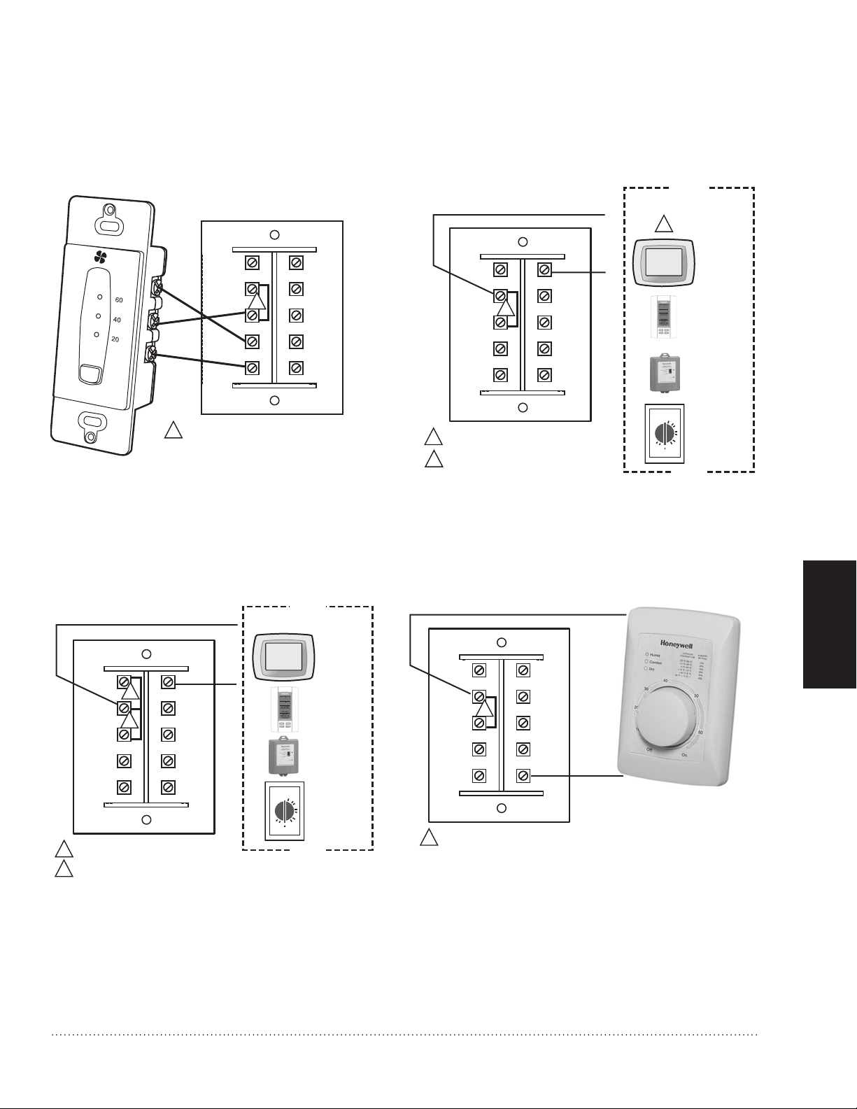
JUMPER BETWEEN VNT COM AND RED.
CHOOSE AMONG AVAILABLE CONTROLS.
ALL WIRE IDENTICALLY.
1
1
2
2
VISIONPRO
IAQ VNT1, 2
TERMINALS
O
10
20
30
40
50
60
W8150
AUX
TERMINALS
CONTROL OPTIONS
MECHANICAL
TIMER DRY
CONTACTS
TRUE IAQ VENT
TERMINALS
68
40
55
1215
:
76
%
%
In
Out
PM
VNT
COM
1
2
3
4
5
6
7
8
9
10
VNT
LOW
RED
YEL
GRN
VNT HI
G
F
R
G
T
DSTAT
M29846
JUMPER BETWEEN VNT COM AND RED.
1
1
20 40 60 TIMER
FAN INTERLOCK
VNT
COM
1
2
3
4
5
6
7
8
9
10
VNT
LOW
VNT
COM
RED
YEL
GRN
VNT HI
G
F
R
G
T
DSTAT
M29845
JUMPER BETWEEN VNT COM AND RED.
JUMPER BETWEEN VNT COM AND VNT LOW.
1
1
VISIONPRO
IAQ VNT1, 2
TERMINALS
O
10
20
30
40
50
60
W8150
AUX
TERMINALS
MECHANICAL
TIMER DRY
CONTACTS
2
TRUE IAQ VENT
TERMINALS
2
68
40
55
1215
:
76
%
%
In
Out
PM
20 40 60 TIMER
FAN INTERLOCK
CONTROL OPTIONS
1
2
3
4
5
6
7
8
9
10
VNT
LOW
VNT
COM
RED
YEL
GRN
VNT
HI
G
F
R
G
T
DSTAT
20 40 60 TIMER
FAN INTERLOCK
M29838
YEL
RED
GRN
JUMPER BETWEEN VNT COM AND RED.
1
1
NOTE: Turn power to ventilator OFF during wiring. A static discharge to the wiring terminals while powered
could cause unit to reset or require power cycling.
Wiring digital fan timer.Fig. 11.
Wiring IAQ or ventilation control.Fig. 12.
HR150, 200; ER150, 200 Perfect Window™ Fresh Air Ventilation Systems 68-0171EF—01
Wiring for continuous low speed and high Fig. 13.
speed override.
WIRING
Wiring dehumidistat.Fig. 14.
13
Page 16
WIRING
1
2
3
4
5
6
7
8
9
10
VNT
LOW
VNT
COM
RED
YEL
GRN
VNT HI
G
F
R
G
T
DSTAT
M29848
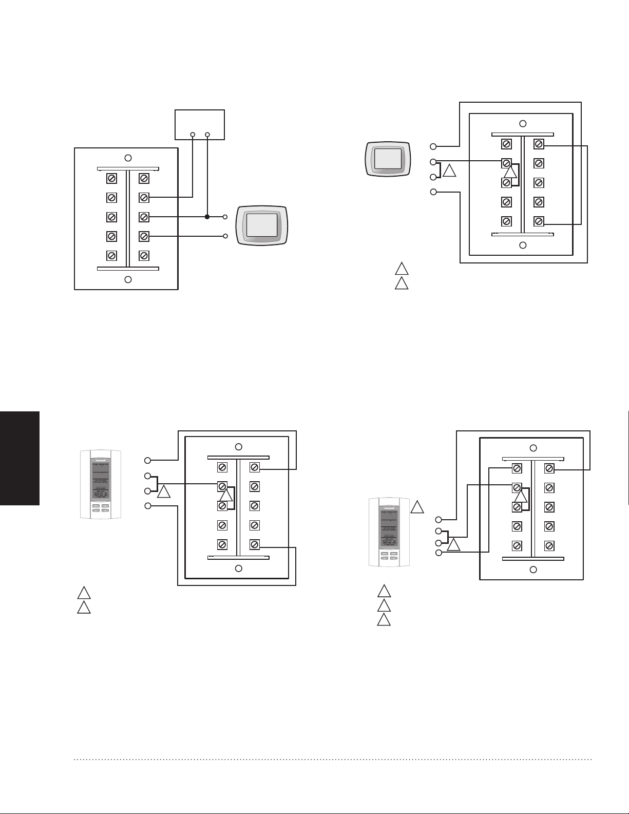
JUMPER BETWEEN VNT COM AND RED.
JUMPER BETWEEN DHM2 AND VNT1.
1
1
2
2
DHM 1
DHM 2
VNT 1
VNT 2
VisionPRO IAQ
20 40 60 TIMER
FAN INTERLOCK
1
2
3
4
5
6
7
8
9
10
VNT
LOW
VNT
COM
RED
YEL
GRN
VNT HI
G
F
R
G
T
DSTAT
M29849
JUMPER BETWEEN VNT COM AND RED.
JUMPER BETWEEN VENT AND DEHUM.
1
1
2
2
VENT
VENT
DEHUM
DEHUM
68
40
55
1215
:
76
%
%
In
Out
PM
TrueIAQ
20 40 60 TIMER
FAN INTERLOCK
1
2
3
4
5
6
7
8
9
10
VNT
LOW
VNT
COM
RED
YEL
GRN
VNT HI
G
F
R
G
T
DSTAT
M29850
JUMPER BETWEEN VENT AND DEHUM.
JUMPER BETWEEN VNT COM AND RED.
LOW SPEED WILL OPERATE IF TrueIAQ IS CONFIGURED TO
LOWER VENTILATION BASED ON OUTDOOR CONDITIONS
(SETUP NUMBER 115=2).
1
2
2
68
40
55
1215
:
76
%
%
In
Out
PM
VENT
VENT
DEHUM
DEHUM
TrueIAQ
1
3
3
20 40 60 TIMER
FAN INTERLOCK
1
2
3
4
5
6
7
8
9
10
VNT
LOW
VNT
COM
RED
YEL
GRN
VNT HI
G
F
R
G
T
DSTAT
M29847
THERMOSTAT
R
G
FURNACE
G
R
20 40 60 TIMER
FAN INTERLOCK
Wiring for fan interlock.Fig. 15.
Wiring VisionPRO IAQ for ventilation and Fig. 16.
dehumidification.
Wiring TrueIAQ for ventilation and Fig. 17.
14
dehumidification.
Wiring TrueIAQ for high and low speed Fig. 18.
ventilation.
HR150, 200; ER150, 200 Perfect Window™ Fresh Air Ventilation Systems 68-0171EF—01
Page 17
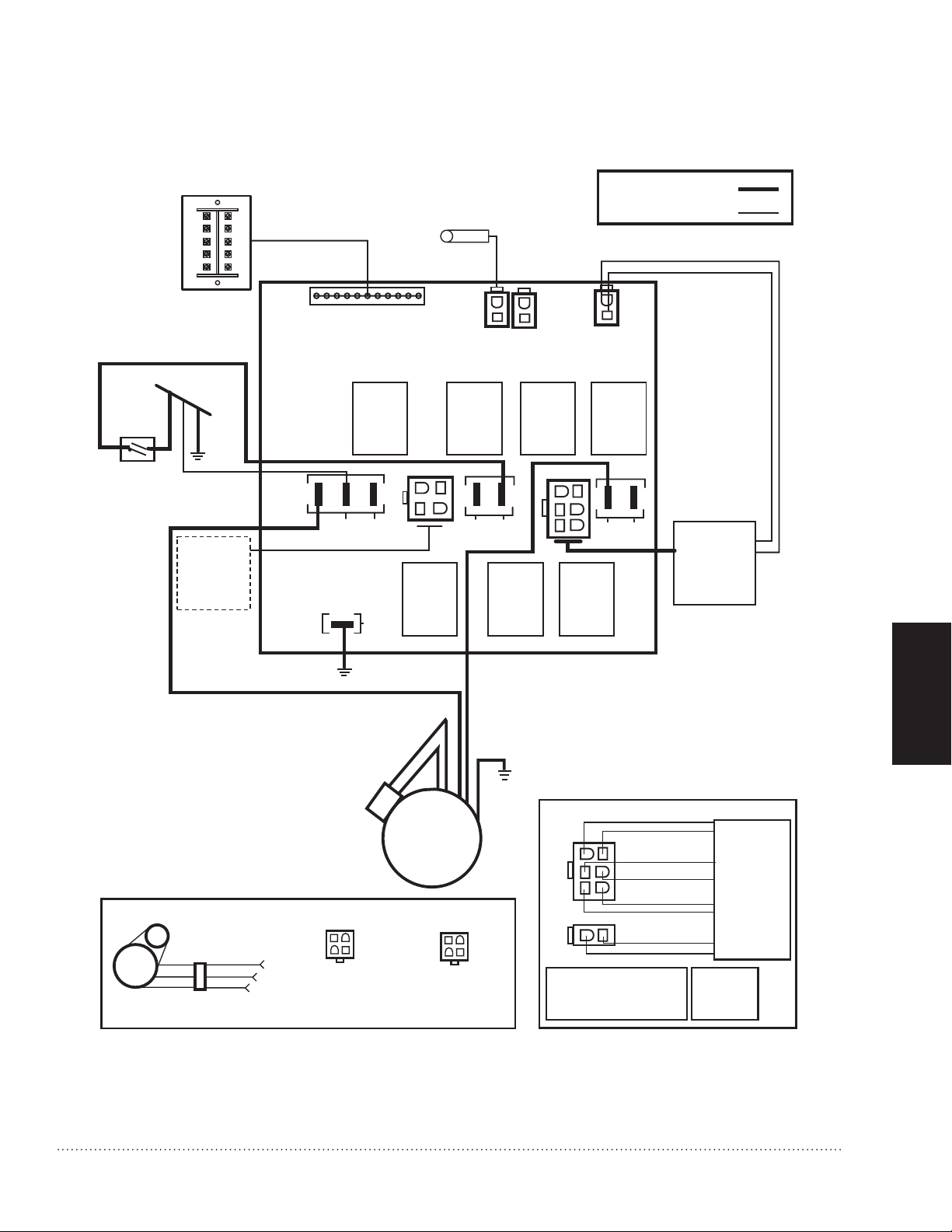
LEGEND
HIGH VOLTAGE
12V LOW VOLTAGE
M29742
K7K2 K3
P2
RED
THERMISTOR
(NOT ON ALL UNITS)
BLACK
GREEN
NEUTRAL
LINE
AUTOTRANSFORMER
SEE
DEFROST
DETAIL
WHITE
P4
BLUE
K4
K6 K1
P3
FAN O/P
T8T7
P1
T3T2
T9
T1
K5
DIRECT
MOUNTED
CAPACITOR
CAPACITOR
DEFROST DETAILS
PCB PLUG-IN
PLUG IN
CONNECTOR
BLACK
RED
ORANGE
ORANGE
12
P1
34
PIN 1–BLACK
PIN 2–ORANGE
PIN 3–RED
PIN 4–SPARE
RED
BLACK
BI-DIRECTIONAL
DAMPER MOTOR
PCB PLUG-IN
12
P1
34
PIN 1–RED
PIN 2–ORANGE
PIN 3–BLACK
PIN 4–SPARE
FAN
MOTOR
BROWN
BROWN
GREEN
BLACK
WHITE
VNT
LOW
VNT
COM
RED
YEL
GRN
VNT HI
G
F
R
G
T
DSTAT
AUTO-TRANSFORMER DETAIL
PIN 1–BLUE
PIN 2–YELLOW
PIN 3–BROWN
PIN 4–RED
PIN 5–WHITE
PIN 6–BLACK
PIN 1–GREEN
PIN 2–GREEN
P5
AUTO
TRANSFORMER
4
5
6
1
2
3
1
2
P6
P5
PLUG-IN CONNECTOR
P6
HR150, 200; ER150, 200 Perfect Window™ Fresh Air Ventilation Systems 68-0171EF—01
Internal schematic for fresh air ventilation systems.Fig. 19.
WIRING
15
Page 18

Airflow Balancing
PUSH AND TURN WITH
SLOTTED SCREWDRIVER.
DAMPER AUTO MATICALLY
LOCKS WHEN PRESSURE
IS RELEASED.
M13462
Volume-balanced airflow in the ventilator is required. Volume of outside air brought in must equal the volume of
air the unit exhausts. If airflow is not correctly balanced:
unit does not operate at its maximum efficiency.•
negative or positive air pressure can occur in the house.•
unit will not defrost properly.•
warranty can be voided.•
Excessive positive pressure can drive moist indoor air into building external walls where it can condense (in cold
weather) and degrade structural components. Moist indoor air can also cause keyholes to freeze.
Excessive negative pressure can have several undesirable side effects; in some geographic locations, soil
gases such as methane and radon can be drawn into the home through basement/ground contact areas.
Excessive negative pressure can also cause back drafting of vented combustion equipment when adequate
combustion air supply is not provided.
Balancing Procedure
Six-inch (150 mm) diameter flow collars connected to inclined or digital manometer, or magnehelic, with
range of 0 to.25 in. (0 to 62.5 Pa) of water are recommended for accurate airflow measurements. To avoid
airflow turbulence and incorrect readings, flow stations should be located at a distant point of at least five duct
diameters; for example, 6 in. (150 mm) duct requires five diameters x 6 in. (150 mm) = 30 in. (76 cm) from
nearest valve or flow restriction. This requirement applies to both stale air to exchanger duct and fresh air to
house duct.
DUCTING
Before balancing, make sure:
all sealing of the ductwork system is completed.•
all of the ventilator system components are in place and functioning properly.•
balancing dampers are fully open.•
unit is on High speed.•
airflows in branch lines to specific areas of house are adjusted before balancing the unit. (A smoke pencil •
used at the grilles is a good indicator of relative airflow for each branch line.)
HVAC fan is on for models ducted into HVAC system.•
After taking readings in stale air and fresh air ducts,
duct with lower cfm (L/s) velocity reading should
remain as is, while duct with higher reading should be
dampered back to match lower reading. See Fig. 20.
Return unit to appropriate fan speed for normal
operation.
Balancing airflow.Fig. 20.
16
HR150, 200; ER150, 200 Perfect Window™ Fresh Air Ventilation Systems 68-0171EF—01
Page 19

STARTUP AND CHECKOUT
When the ventilator is powered up it will go through a self-test and turn on both fan speeds and check damper
operation.
LED on Terminal Board of Ventilator
The terminal board has an LED that flashes to indicate the current mode of the ventilator.
Ventilator Mode Flashing Sequence Description
Standby, Ventilating,
or Off*
Self-Test 2-½ sec. on followed by ½ sec. off Self-test will turn on both fan speeds and check damper
Defrost ½ sec. on followed by ½ sec. off See page 9 for defrost operation
* In Off mode the ventilator will not come on. The ventilator is in Off mode when there is no jumper between
VNT COM and RED. The jumper can be replaced with an ON/OFF light switch to provide an easy positive off
switch.
½ sec. on followed by 10 sec. off This is the normal operation of the ventilator.
operation.
SERVICE
CAUTION: Electrical shock hazard.
Can cause personal injury or equipment damage.
Disconnect power to unit before starting
maintenance.
For maximum efficiency, the Fresh Air Ventilation
System must be maintained on a regular basis.
Honeywell recommends checking and cleaning at
least twice a year, preferably at the beginning of each
heating and cooling season.
Cleaning Filters and Core
Open ventilator door by loosening draw latches on top of 1.
unit and swinging door open. For easier access, remove
door by moving it right to disengage hinges.
Carefully grip ends of core, (be careful not to damage 2.
aluminum fins); then pull evenly outward. Core fits tightly,
but slides out of channels.
Once core is removed, filters can be removed by 3.
removing clips holding them in place. Note clip
installation for reassembly.
ERV core: Vacuum the ERV core or rinse with cold water. 4a.
Do not use soap, dishwasher, or a pressure washer.
HRV core: Soak and rinse the HRV core in warm soapy 4b.
water. Do not use cleaning solutions, dishwasher or a
pressure washer.
Wash the filters in warm soapy water.5.
Place the clean filter (wet or dry) over the core and 6.
secure it in place with the clips.
Reinstall core by sliding it into the four corner channels. 7.
(Water cannot damage gasket and label on core ends,
so it is not necessary to remove them from the core.)
Inspecting Exterior Hoods
Inspect exterior hoods at least monthly. Be sure
exhaust and fresh air supply hoods are not blocked
or restricted by leaves, grass or snow. In winter, be
sure snow does not block hoods and frost does not
accumulate on wire mesh bird screen.
IMPORTANT
Blocked hoods can cause house/building pressure
change that can lead to possible combustion product
spillage from heating appliances.
APPENDICES
HR150, 200; ER150, 200 Perfect Window™ Fresh Air Ventilation Systems 68-0171EF—01
17
Page 20

TROUBLESHOOTING
Table 1. Troubleshooting Guide.
Symptom Cause Solution
Poor airflow Plugged outside hood 1/4 in. (6 mm) mesh.• Clean exterior hoods or vents•
Filters plugged.• Remove and clean filter.•
Core obstructed.• Remove and clean core.•
House grilles closed or blocked.• Check and open grilles.•
Dampers (if installed) are closed.• Open and adjust dampers•
Poor power supply at site.• Have electrician check supply voltage at house.•
Ductwork is restricting airflow.• Check duct installation.•
Improper speed control setting.• Increase speed of ventilator.•
Ventilator airflow improperly balanced.• Have contractor balance ventilator airflow.•
Supply air
feels cold
Dehumidistat
is not
operating
Poor location of supply grilles, airflow can •
irritate the occupant.
Outdoor temperature extremely cold.• Turn down ventilator supply speed.•
Ventilator airflow can be incorrectly balanced.• Have a contractor balance ventilator airflow.•
Incorrect connection to external 24-volt control.•
Staple/nail is shorting out external low voltage.•
Check dehumidistat setting; it could be at Off.• Set dehumidistat at the desired setting.•
Dehumidistat is disabled when the outdoor •
temperature is above 60F for 24 hours.
Locate grilles high on walls or under baseboard •
heaters; install ceiling-mounted diffuser or
grilles to avoid blowing directly on occupants
(example: over a sofa).
Use a small duct heater (1 kW) to temper the •
supply air.
Placement of furniture or closed doors is •
restricting movement of air in the home.
If supply air is ducted in furnace return, run •
furnace fan continuously to distribute ventilation
air comfortably.
Check that correct wires were used.•
Check external wiring for a short.•
Check the LED on the terminal block for long •
flash followed by a short flash.
APPENDICES
18
HR150, 200; ER150, 200 Perfect Window™ Fresh Air Ventilation Systems 68-0171EF—01
Page 21

Symptom Cause Solution
Humidity
levels are
too high;
condensation
appears on
windows
Dehumidistat is set too high. Set dehumidistat lower.
Undersized ventilator to handle hot tub, indoor •
Cover pools and hot tubs when not in use.•
pool, etc.
Lifestyle of occupants.• Avoid hanging clothes to dry, storing wood and •
venting clothes dryer inside. Consider moving
wood outside.
Humidity
levels too low
Ventilator and/
or ducts have
frost buildup
Condensation
or ice buildup
in insulated
duct to
outside
Water in
ventilator
bottom
Moisture coming into home from crawl space •
not vented or heated.
Moisture is remaining in bathroom and kitchen •
areas.
Condensation is forming in spring and fall.• On humid days, as seasons change, •
Ventilator speed is set too low.• Increase speed of ventilator.•
Ventilator airflow can be incorrectly balanced.• Have a contractor balance ventilator airflow.•
Dehumidistat control set too low.• Set dehumidistat higher.•
Blower speed of ventilator is too high.• Decrease ventilator blower speed.•
Lifestyle of occupants.• Increase humidity with humidifiers.•
Ventilator airflow can be incorrectly balanced.• Have a contractor balance ventilator airflow.•
Ventilator airflow is incorrectly balanced. • NOTE: Minimal frost build-up is expected on •
Malfunction of ventilator defrost system.• Have HVAC contractor check defrost system.•
Incomplete vapor barrier around insulated duct.• Tape and seal all joints.•
Hole or tear in outer duct covering.• Ensure vapor barrier is completely sealed.•
Drain pans are plugged.•
Improper connection of ventilator drain lines.•
Ventilator is not level.• Level ventilator.•
Drain lines are obstructed.• Check water drain connections.•
Ventilator heat exchange not correctly installed.• Make sure water drains correctly from pan.•
Vent crawl space and place vapor barrier on •
floor of crawl space.
Size bathroom ducts to remove moist air as •
effectively as possible; use bathroom fan to
remove additional moisture.
condensation appears but air quality remains
high with some ventilator use. Use a control that
provides ventilation in all seasons.
cores before unit initiates defrost cycle functions.
Have HVAC contractor balance ventilator.•
Tape any hole or tears made in outer duct •
covering.
Ensure O-ring on drain nozzle adjusted correctly.•
Look for kinks in line.•
APPENDICES
HR150, 200; ER150, 200 Perfect Window™ Fresh Air Ventilation Systems 68-0171EF—01
19
Page 22

PARTS LIST
HR/ER Parts List
Item
Number
(Fig. 21)
1 209746 Heat Transfer Core, Aluminum with Plastic Frame
2 208359 208359 208359 Blower Motor with Capacitor
3 50002341-001 50002341-001 50002341-001 Blower Housing Kit, includes upper and lower housing, no
4 209723 50050728-001 50050728-001 Foam Prefilter, Set of 2
5 209722 Included with
6 209715 209715 N/A Defrost Damper Motor, Bi-directional
7 50048693-001 50048693-001 N/A Drain Spouts and “T” Kit
8 50048694-001 50048694-001 50048694-001 Door latch, double wide
9 50050832-001 50050832-001 50050832-001 Electronic Control Kit (Control Board and Auto Transformer)
* Date can be determined by serial number which includes date in MMDDYY format.
Shaded items are obsolete — available while supplies last.
Part Number for Description
HR150B/
HR200B
ER150B/
ER200B
32002074-001 32002074-001 Cross-Flow Energy Transfer Core, with Guide Channels,
50048918-001 50048918-001 Universal Energy Transfer Core with guide channels to fit
Prefilter
ER150C/
ER200C
Included with
Prefilter
diamond shape made before August 2005*
diamond and square shape.
wheels or motor.
Clip for HRV Foam Prefilter
APPENDICES
Accessory Items Parts List Not Shown—All Models
Item
Number
6 W8150A1001 Fresh Air Ventilation Control
7 50050477-001 Digital Fan Timer, 20, 40, 60 minutes
Part Number Description
20
HR150, 200; ER150, 200 Perfect Window™ Fresh Air Ventilation Systems 68-0171EF—01
Page 23

M29855
2
3
7
9
8
4
5
6
1
1
HR150/HR200 and ER150/ER200 exploded view of parts keyed to HR/ER Parts List.Fig. 21.
APPENDICES
HR150, 200; ER150, 200 Perfect Window™ Fresh Air Ventilation Systems 68-0171EF—01
21
Page 24

Specifications
IMPORTANT
TRADELINE® Models
TRADELINE models are selected and packaged to
provide ease of stocking, ease of handling and maximum
replacement value.
TRADELINE Models Available:
Color
White
Electrical Ratings
APPENDICES
The specifications given in this publication do
not include normal manufacturing tolerances.
Therefore, this unit might not exactly match the
listed specifications. Also, this product is tested
and calibrated under closely controlled conditions,
and some minor differences in performance can be
expected if those conditions are changed.
HR150 and HR200 Fresh Air Ventilation Systems: •
Includes heat transfer core, prefilters, fan and blower
assembly and frost control.
ER150, ER200 Fresh Air Ventilation Systems: Includes •
enthalpic heat and moisture transfer core, prefilters, fan
and blower assembly and frost control (frost control on B
models only).
HR150B: 150 cfm, aluminum cross flow core, manual •
control and frost control.
HR200B: 200 cfm, aluminum cross flow core, manual •
control and frost control.
ER150B: 150 cfm, heat and moisture transferring core, •
manual control and frost control.
ER150C: 150 cfm, heat and moisture transferring core, •
manual control and without frost control.
ER200B: 200 cfm, heat and moisture transferring core, •
manual control and frost control.
ER200C: 200 cfm, heat and moisture transferring core, •
manual control and without frost control.
Power Rating: 120 Vac, 60 Hz•
Amp Rating: 1.4 A•
Consumption:•
Watts
Mode
Low speed 63 70
High speed 173 182
HR150/ER150 HR200/ER200
Mounting
Most models mount in conditioned space such as a
basement, utility room, hallway or closet. Can also be
mounted in conditioned attic space.
NOTE: ER150C and ER200C models can be installed in
unconditioned spaces such as attics and garages
in regions where the outdoor temperature does not
drop below freezing.
Approvals
Home Ventilation Institute (HVI): Certified.•
Canadian Standards Association: Approved.•
ETL: Certified to UL1812.•
Installed Weight
HR150/HR200: 70 lb (32 kg).•
ER150/ER200: 70 lb (32 kg).•
HVI Certified
HR150, HR200, ER150, ER200
Ventilation Performance
See Fig. 22 and 24.
Dimensions
See Fig. 23 and 25.
Accessories
See the Accessory Items Parts List that follows the
Troubleshooting Guide.
HR150, HR200
Performance ratings based on CAN/CSA-C439-88.
Maximum Temperature Recovery
78%
Sensible Effectiveness
HR150 at 67 cfm (32 L/s) at 32°F (0°C): 76%.
HR200 at 119 cfm (56 L/s) at 32°F (0°C): 67%.
ER150, ER200
Sensible Effectiveness
ER150 at 64 cfm (30 L/s) at 32°F (0°C): 81%.
ER200 at 116 cfm (55 L/s) at 32°F (0°C): 76%.
Total Recovery Efficiency
ER150 at 65 cfm (30 L/s) at 95°F (35°C): 47%.
ER200 at 117 cfm (30 L/s) at 95°F (35°C): 50%.
22
HR150, 200; ER150, 200 Perfect Window™ Fresh Air Ventilation Systems 68-0171EF—01
Page 25

M29743B
25
50
75
100
125
150
175
.1
.2
.3
.4
.5
.6
.7
83
77
73
67
58
47
18
177
164
156
143
123
100
38
EXT STATIC
PRESSURE
(Pa)(in. wg)(L/s) (cfm)
NET SUPPLY
AIR FLOW
HR150 VENTILATION PERFORMANCE (HV1)
20
40
60
80
100
120
140
160
180
200
00.1 0.20.3 0.40.5 0.60.7 0.8
STATIC PRESSURE (IN W.G.)
AIR FLOW (CFM)
MANUFACTURER’S DATA
1
1
HIGH SPEED
LOW SPEED
M29744B
.1
.2
.3
.4
.5
.6
.7
101
97
91
87
80
73
65
214
206
193
184
170
155
137
EXT STATIC
PRESSURE
(Pa)(in. wg)(L/s) (cfm)
NET SUPPLY
AIR FLOW
HR200 VENTILATION PERFORMANCE (HVI)
25
50
75
100
125
150
175
20
40
60
80
100
120
140
160
180
200
220
240
00.1 0.20.3 0.40.5 0.60.7 0.8
STATIC PRESSURE (IN W.G.)
AIR FLOW (CFM)
MANUFACTURER’S DATA
1
HIGH SPEED
LOW SPEED
1
STALE
AIR FROM
INSIDE
DEFROST
PORT
FRESH
AIR TO
INSIDE
FRESH AIR
FROM OUTSIDE
STALE
AIR TO
OUTSIDE
M29741
A
DEFROST
DAMPER
CONDENSATE
DRAINS
BALANCING
DAMPER
BLOWERS
FILTERS
14-3/4
(375)
19
(483)
FRONT CLEARANCE OF 25 INCHES (635 MM)
IS RECOMMENDED FOR SERVICING UNIT.
ALL DUCT
CONNECTIONS
6 (150)
MOUNTING
SCREWS
1
1
BALANCING
DAMPER
33-5/8
(850)
HR150, 200; ER150, 200 Perfect Window™ Fresh Air Ventilation Systems 68-0171EF—01
HR150 and HR200 Ventilation performance.Fig. 22.
HR150 and HR200 dimensions in in. (mm).Fig. 23.
APPENDICES
23
Page 26

HIGH SPEED
LOW SPEED
220
200
180
160
140
120
100
80
60
40
20
0
0 0.1 0.2 0.3
0.4
0.5
0.6
0.7
0.8
AIR
FLOW
(CFM)
STATIC PRESSURE (IN. W.G.)
M29836
0.1 (25)
0.2 (50)
0.3 (75)
0.4 (100)
0.5 (125)
0.6 (150)
0.7 (175)
0.8 (200)
E.S.P.
(EXTERNAL STATIC PRESSURE)
INCHES (Pa)
CFM (Ls)
ER150 VENTILATION PERFORMANCE
NET SUPPLY AT LOW IN CFM (L/s) AGAINST EXTERNAL STATIC PRESSURE
151 (71)
141 (67)
132 (62)
124 (59)
107 (50)
98 (46)
81 (38)
60 (28)
MANUFACTURER’S DATA .
1
1
M29837
0.1 (25)
0.2 (50)
0.3 (75)
0.4 (100)
0.5 (125)
0.6 (150)
0.7 (175)
0.8 (200)
E.S.P.
(EXTERNAL STATIC PRESSURE)
INCHES (Pa)
CFM (Ls)
ER200 VENTILATION PERFORMANCE
NET SUPPLY AT LOW IN CFM (L/s) AGAINST EXTERNAL STATIC PRESSURE
180 (85)
169 (80)
157 (74)
146 (69)
132 (62)
118 (56)
101 (48)
82 (39)
MANUFACTURER’S DATA .
1
HIGH SPEED
LOW SPEED
220
200
180
160
140
120
100
80
60
40
20
0
0 0.1 0.2 0.3
0.4
0.5
0.6
0.7
0.8
AIR
FLOW
(CFM)
STATIC PRESSURE (IN. W.G.)
1
FILTERS (2)
M29856
MOTOR
BLOWERS
ENERGY
TRANSFER
CORE
BALANCING
DAMPER
19
(483)
14-3/4
(375)
33-5/8
(850)
CORE
BALANCING
DAMPER
FRONT CLEARANCE OF 25 INCHES (635 MM)
IS RECOMMENDED FOR SERVICING UNIT.
ALL DUCT CONNECTIONS ARE 6 (150).
1
2
1
2
MOUNTING
SCREWS
DEFROST
PORT
STALE
AIR FROM
INSIDE
FRESH
AIR TO
INSIDE
STALE
AIR TO
OUTSIDE
FRESH AIR
FROM
OUTSIDE
APPENDICES
24
ER150 and ER200 Ventilation performance.Fig. 24.
ER150 and ER200 dimensions in in. (mm).Fig. 25.
HR150, 200; ER150, 200 Perfect Window™ Fresh Air Ventilation Systems 68-0171EF—01
Page 27

Page 28

Automation and Control Solutions
Honeywell International Inc.
1985 Douglas Drive North
Golden Valley, MN 55422
Honeywell Limited–Honeywell Limitée
35 Dynamic Drive
Toronto, Ontario M1V 4Z9
http://yourhome.honeywell.com
® U.S. Registered Trademark
© 2010 Honeywell International Inc.
68-0171EF—01 M.S. 03-10
Printed in U.S.A.
Page 29

M29857
68-0171EF-01
Systèmes de ventilation à apport d’air frais
Perfect Window™ HR150, 200; ER150, 200
DONNÉES SUR LE PRODUIT
Inclus dans la Boîte du système
COMMENCER
POUR
de VentIlatIon
F1 F3
COMMANDES EN OPTION VENDUES SÉPARÉMENT
Outils et accessoires requis pour l’installation des
systèmes de ventilation à apport d’air frais Perfect
Window™
Coupe-fil/outil à dénuder
Fil de calibre 18 (jusqu’à 5 conducteurs))
Tournevis normal
Conduit rond isolé de 6 po
Conduit rond non isolé de 6 po
Deux hottes anti-intempéries de 6 po
Deux collets de départ de 6 po
Tuyau d’évacuation de ½ po de dia. int.
Nécessaire d’équilibrage du débit d’air
Ruban métallique
*
F2
F4 F5
Système de ventilation à apport d’air
frais Perfect Window™ HR150/200 ou
ER150/200
Manuel du propriétaire
Brides de suspension
* Raccord en T
* 2 becs d’évacuation
e
Régulateur VisionPRO IAQ
F1
TrueIAQ
F2
Déshumidistat H8908
F3
F4
Minuterie de ventilateur numérique
F5
Régulateur de ventilation W8150
MONTAGE PLOMBERIE CÂBLAGE ANNEXESTUYAUTERIE
e
*
Pas pour les modèles « C ».
*
Page 30

Page 31

Systèmes de ventilation à apport d’air frais Perfect Window
POUR COMMENCER
Définitions et précautions relatives à la sécurité .... 2
Application ................................. 3
Caractéristiques. . . . . . . . . . . . . . . . . . . . . . . . . . . . . 3
Préparation de l’installation .................... 4
Dimensionnement . . . . . . . . . . . . . . . . . . . . . . . . . . . 5
Position et emplacement de montage ............ 6
Équilibrage du débit d’air ...................... 9
MONTAGE
Installation ................................ 10
Suspension aux solives de plancher ............ 10
PLOMBERIE
Installation du tuyau d’évacuation et du siphon P . . 11
CÂBLAGE
Raccordements du ventilateur à récupération de
chaleur (VRC) et du ventilateur à récupération
d’énergie (VRE) ............................ 12
Minuterie de ventilateur numérique ............. 12
COMMENCER
POUR
MONTAGE PLOMBERIE CÂBLAGE ANNEXES
TUYAUTERIE
Équilibrage du débit d’air ..................... 16
Procédure d’équilibrage ...................... 16
ANNEXES
Démarrage et vérification . . . . . . . . . . . . . . . . . . . . 17
Nettoyage des filtres et du noyau ............ 17
Inspection des hottes extérieures ............ 17
Dépannage . . . . . . . . . . . . . . . . . . . . . . . . . . . . . . . 18
Liste des pièces ............................ 20
Spécifications . . . . . . . . . . . . . . . . . . . . . . . . . . . . . 22
BESOIN D’AIDE? Pour de l’assistance au sujet de ce produit, merci de consulter le site
?
http://yourhome.honeywell.com ou d’appeler le numéro gratuit du service à la clientèle de
Honeywell au 1-800-468-1502.
TUYAUTERIE
Lire et conserver ces instructions.
® Marque déposée américaine. Brevets en instance. Copyright © 2010 Honeywell International Inc. Tous droits réservés.
Systèmes de ventilation à apport d’air frais Perfect Window™ HR150, 200; ER150, 200 68-0171EF—01
1
Page 32

Définitions et précautions relatives à la sécurité
Définitions relatives à la sécurité
L’information portant sur l’identification des termes de sécurité doit être lue.
POUR
COMMENCER
MISE EN GARDE : Indique une situation dangereuse qui, si elle n’est pas évitée, risque d’endommager le
produit ou de causer des blessures corporelles.
AVERTISSEMENT : Indique une situation dangereuse qui, si elle n’est pas évitée, risque de causer des
blessures graves, voire mortelles.
Précautions relatives à la sécurité
Veiller à lire et à comprendre les avertissements relatifs à la sécurité et aux dommages matériels
suivants avant d’installer, d’utiliser ou de travailler sur le système de ventilation à apport d’air frais
Perfect Window™ :
Toute la tuyauterie en direction de l’extérieur doit se terminer au-dessus des lignes de limites de neige •
prévues et être munie de bouchons anti-intempéries équipés d’un grillage aviaire.
MISE EN GARDE : Risque de choc électrique.
Peut causer des blessures et des dommages matériels.
Débrancher l’alimentation pour éviter les chocs électriques et les dommages matériels.
MISE EN GARDE : Risque de choc électrique.
Peut causer des blessures.
Veiller à ce que le ventilateur soit correctement mis à la masse. Confirmer la polarité des lignes électriques
utilisant un interrupteur de sécurité (déconnexion) lors du nettoyage ou de l’entretien de l’unité.
MISE EN GARDE : Risque de choc électrique.
Peut endommager l’équipement
Débrancher le VRC/VRE de l’alimentation avant de connecter ou de déconnecter la minuterie du ventilateur
numérique ou un autre appareil des bornes de dérivation haute vitesse du VRC/VRE.
2
Systèmes de ventilation à apport d’air frais Perfect Window™ 68-0171EF—01
Page 33

Application
HR150B et HR200B de Honeywell procurent une ventilation adéquate tout en réduisant la consommation
d’énergie; ils transfèrent en effet à l’air neuf la chaleur contenue dans l’air extrait.
Le système de ventilation par apport d’air frais Perfect Window™ ER150B et ER200B de Honeywell procure une
ventilation adéquate tout en réduisant la consommation d’énergie; il transfère en effet la chaleur et l’humidité
contenue entre les flux d’air d’évacuation et d’air frais.
Les systèmes de ventilation à apport d’air frais Perfect Window™ ER150C et ER200C sont spécifiquement
conçus pour les installations dans les espaces non climatisés, tels que les greniers et les garages dans les
régions où la température extérieure ne descend pas en dessous de 0 °C (32 °F).
Caractéristiques
Ventilateur à deux vitesses à commande à distance.•
Registres d’équilibrage intégrés pour une installation rapide.•
Fournit une ventilation qui permet aux entrepreneurs d’assurer une ventilation conforme à la norme ASHRAE •
62
Commande de dégivrage intégrée, automatique et économique disponible pour un fonctionnement aux •
températures de calcul de -40 °C (-40 °F).
Les modèles HR150 et HR200 ont un noyau à débit croisé en aluminium facile à nettoyer.•
Les modèles ER150 et ER200 ont un noyau fixe à récupération d’énergie, de chaleur et d’humidité de •
technologie avancée
Noyau de transfert d’énergie lavable. Inclut le matériel d’isolation des vibrations et des collets de conduit.•
Armoire isolée en acier robuste•
Préfiltres permanents (lavables)•
Fonctionnement silencieux•
Option de minuterie de ventilateur numérique sur tous les modèles•
Algorithmes de ventilation avancés disponibles sur les régulateurs VisionPRO IAQ, TrueIAQ et W8150•
Raccorder le VRC/VRE sur la soufflante de la section de traitement de l’air ou de l’appareil chauffage•
Fonctionnement du déshumidistat désactivé l’été•
COMMENCER
POUR
Systèmes de ventilation à apport d’air frais Perfect Window™ 68-0171EF—01
3
Page 34

POUR
AIR
RANCE DE
L’INTÉRIEUR
ORIFICE DE
DÉGIVRAGE
AIR FRAIS
VERS
L’INTÉRIEUR
AIR FRAIS DE L’EXTÉRIEUR
AIR RANCE
VERS
L’EXTÉRIEUR
MF29739
REGISTRE D’ÉQUILIBRAGE
FILTRES
FILTRES (2)
ÉVACUATION
MF29853
MOTEUR
SOUFFLANTES
AIR FRAIS DE
L’EXTÉRIEUR
ORIFICE DE
DÉGIVRAGE
BACS DE RÉCUPÉRATION
REGISTRE
D’ÉQUILIBRAGE
REGISTRE
D’ÉQUILIBRAGE
CORE
AIR
RANCE DE
L’INTÉRIEUR
AIR FRAIS
VERS
L’INTÉRIEUR
AIR RANCE
VERS
L’EXTÉRIEUR
AIR FRAIS DE
L’EXTÉRIEUR
MF29861
MOTEUR
MOTEUR
AIR RANCE
DE LA
MAISON
NOYAU DE
TRANSFERT
D’ÉNERGIE
NOYAU
REGISTRE
D’ÉQUILIBRAGE
REGISTRE
D’ÉQUILIBRAGE
FILTRES (2)
AIR FRAIS
VERS
L’INTÉRIEUR
AIR RANCE
VERS
L’EXTÉRIEUR
COMMENCER
Préparation de l’installation
Le non-respect de ces exigences annulera la garantie, nuira à l’installation et entraînera des appels
de service injustifiés.
Le système de ventilation à apport d’air frais est
conçu pour apporter de l’air frais et évacuer l’air
rance. Le système aspire l’air frais extérieur par le
ventilateur pour le distribuer dans la maison.
Ventilateur à récupération d’énergie
L’air rance est évacué à l’extérieur par le
ventilateur. La chaleur est transférée d’un flux d’air
à l’autre pendant que l’air passe par les côtés
Raccordement des conduits et débit d’air Fig. 1.
(HR150B/HR200B).
opposés du noyau de transfert de chaleur. Voir la
Fig. 1.
4
Raccordement des conduits et débit d’air Fig. 2.
Raccordement des conduits et débit d’air Fig. 3.
(ER150C/ER200C).
(ER150B/ER200B).
Ventilateur à récupération d’énergie
L’air rance est évacué à l’extérieur par le
ventilateur. La chaleur et l’humidité sont
transférées d’un flux d’air à l’autre pendant que
l’air passe par les côtés opposés du noyau de
transfert d’énergie. Voir les Fig. 2 et 3.
Systèmes de ventilation à apport d’air frais Perfect Window™ 68-0171EF—01
Page 35

Dimensionnement
ASHRAE 62.2
Plusieurs méthodes peuvent donner des résultats
satisfaisants pour dimensionner le ventilateur requis
pour fournir une ventilation adéquate à l’habitation. La
nouvelle norme de ventilation résidentielle ASHRAE
62.2 donne les suggestions suivantes :
3
7,5 pi•
/min. par personne (compter le nombre de
personnes tel que 1 par chambre à coucher plus 1)
plus 1 pi3/min. par 100 pi
2
Exemple :
Maison de 2200 pi2 avec 4 chambres à coucher
= (7,5 pi3/min. x (4 chambres à coucher + 1)) + (1 pi3/min. x (2200
pi2 / 100))
= (7,5 x 5) + (2200 / 100)
= 37,5 + 22
= 59,5 pi3/min.
Dans ce cas, une capacité de 60 pi3/min. continus
fournirait une ventilation adéquate pour cette
habitation.
ASHRAE 62.1
Certaines régions utilisant la norme plus ancienne
ASHRAE 62.1 en tant que code de ventilation pour leur
région.
La norme de ventilation ASHRAE 62.1 relative à
la qualité de l’air intérieur acceptable donne les
suggestions suivantes :
0,35 changement d’air par heure (cah) mais pas •
moins de 15 pi3/min. pour les zones habitables =
taille de l’habitation (pi2) x hauteur du plafond (pi) /
60 (min) x 0,35 (cah)
Exemple :
= 2000 pi2 x 8 pi / 60 min x 0,35 cah = 93 pi3/min.
Exemple :
50 pi3/min. intermittents x 3 salles de bains = 150 pi3/
min.
20 pi3/min. continus x 3 salles de bains = 60 pi3/min.
Capacité de 100 pi•
3
/min. intermittents ou 25 pi3/min.
continus pour les cuisines
Exemple :
100 pi3/min. intermittents x 1 cuisine = 100 pi3/min.
25 pi3/min. continus x 1 cuisine = 25 pi3/min.
Option 1 : Le système de ventilation à apport d’air frais
fournit une alimentation en air frais continue de 93 pi3/
min. et une capacité intermittente de 150 pi3/min. pour
les salles de bains. Un ventilateur d’aspiration séparé
de 100 pi3/min. est utilisé pour la hotte de la cuisinière.
Débit d’air fourni requis = 93 pi3/min.
Débit d’air évacué requis = 150 pi3/min.
Toutes les unités de ventilation de Honeywell
fournissent une capacité de ventilation adéquate. Voir
la Fig. 22.
Option 2 : Le système de ventilation à apport d’air frais
fournit une alimentation en air frais continue de 93 pi3/
min., une capacité d’évacuation de l’air intermittente de
150 pi3/min. pour les salles de bains et de 50 pi3/min.
pour les cuisines.
Débit d’air fourni requis = 93 pi3/min.
Débit d’air évacué requis = 200 pi3/min.
Les modèles HR200/ER200 de Honeywell ont la
capacité d’évacuation requise pour les besoins en
ventilation de cette application. Voir la Fig. 22.
COMMENCER
POUR
Capacité de 50 pi•
3
/min. intermittents ou 20 pi3/min.
continus pour les salles de bains
Systèmes de ventilation à apport d’air frais Perfect Window™ 68-0171EF—01
5
Page 36

Position et emplacement de montage
CONDUIT
FLEXIBLE
ISOLÉ
COLLET SUR
VENTILATEUR
ÉTANCHÉISER LE REVÊTEMENT INT.
DU CONDUIT FLEXIBLE SUR LE COLLET INT.
É
TANCHÉISER LE REVÊTEMENT EXT.
DU CONDUIT FLEXIBLE SUR LE COLLET EXT.
MF6557
POUR
COMMENCER
Les modèles HR150/ER150 et HR200/ER200 peuvent
être suspendus aux solives de plafond exposées, à
la surface du plafond ou montés au sol. (Mettre le
ventilateur à niveau pour que l’évacuation fonctionne
correctement.)
REMARQUE : Les modèles ER150C et ER200C sont
spécifiquement conçus pour les installations dans
les espaces non climatisés, tels que les greniers
et les garages dans les régions où la température
extérieure ne descend pas en dessous de 0 °C
(32 °F). (Ces unités ne sont pas équipées de
nécessaires d’évacuation.)
Situer l’arrivée d’air frais à 2 m (6 pi) ou plus de •
l’évacuation d’air rance pour éviter que l’air évacué
ne pénètre de nouveau.
Situer le ventilateur à l’endroit nécessitant le moins •
de longueur de tuyauterie.
Installer les modèles HR150/ER150 et HR200/
ER200 dans les endroits climatisés en respectant les
instructions suivantes :
Raccorder le conduit d’évacuation (les modèles •
ER150C et ER200C ne sont pas munis de
nécessaires d’évacuation) du ventilateur à un
orifice d’évacuation.
Utiliser une prise électrique existante au courant •
approprié (ou en installer une) près du cordon
d’alimentation du ventilateur.
Prévoir l’espace pour le conduit d’évacuation en •
plaçant le ventilateur à au moins 254 mm (10 po)
du sol.
Pour l’accès et le retrait du noyau du ventilateur, •
prévoir un espace ouvert d’au-moins 635 mm (25
po) à l’avant de l’unité.
Tuyauterie
Étanchéisation des extrémités de tuyaux isolésFig. 4.
La tuyauterie entre le ventilateur et l’extérieur doit être
isolée et avoir une barrière de vapeur d’air continue.
Voir la Fig. 4.
IMPORTANT
Toute la tuyauterie en direction de l’extérieur doit se
terminer au-dessus des lignes de limites de neige
prévues et être munie de bouchons anti-intempéries
équipés d’un grillage aviaire.
6
Systèmes de ventilation à apport d’air frais Perfect Window™ 68-0171EF—01
Page 37

La conception et l’installation de la tuyauterie doivent être conformes aux pratiques de CVCA standard pour
RETOUR
D’AIR FROID
A
IR D’ÉVACUATION DE
DIVERSES ZONES DE
L’HABITATION (SALLES
DE BAINS OU CUISINES SI
REQUIS; PIÈCES SANS
FENÊTRES FONCTIONNELLES ET
ÉVENTUELLEMENT SOUS-SOLS).
APPAREIL DE
CHAUFFAGE À
AIR PULSÉ
À COMBUSTION
OU ÉLECTRIQUE
MF6549
AIR DE
RETOUR
EXTÉRIEUR
REMARQUES :
1.
2.
3.
4.
IL N’EST PAS NÉCESSAIRE QUE LA SOUFFLANTE DE L’APPAREIL DE CHAUFFAGE FONCTIONNE POUR
ASSURER UNE BONNE DISTRIBUTION/QUALITÉ DE L’AIR AVEC CE SYSTÈME.
S’IL EST REQUIS QUE LA SOUFFLANTE DE L’APPAREIL DE CHAUFFAGE FONCTIONNE POUR FACILITER LA
DISTRIBUTION DE L’AIR FOURNI : FAIRE TOURNER EN CONTINU OU INTERCONNECTER ÉLECTRIQUEMENT
(BASSE TENSION).
PAS DE SÉPARATION REQUISE ENTRE LE POINT DE CONNEXION DIRECT ET L’APPAREIL DE CHAUFFAGE.
LA DISPOSITION DE LA HOTTE ANTI-INTEMPÉRIES EST UNIQUEMENT FOURNIE POUR L’ILLUSTRATION.
UNE SÉPARATION DE 2 M (6 PI) MINIMUM EST REQUISE, 0,46 M (18 PO) SUPÉRIEUR À LA SURÉLÉVATION MINIMUM.
fournir les quantités d’air frais requises à l’espace à température contrôlée et permettre l’évacuation vers
l’extérieur de quantités d’air ambiant équivalentes.
Garder les tuyauteries d’arrivée et d’évacuation aussi courtes que possible et réduire au minimum le nombre de
coudes.
Garder la taille des tuyaux aussi grande que possible sur toute l’installation.•
Utiliser des conduits ronds de 6 po de diamètre pour tous les raccords vers le ventilateur ou depuis celui-ci.•
Séparer les évents d’arrivée et d’échappement externes d’au moins 2 m (6 pi).•
REMARQUES : Ne pas situer l’évent d’air frais à un endroit où il serait dirigé vers les personnes ou le thermostat.
Ne pas situer l’arrivée d’air frais près de sources connues de polluants, tels que les gaz d’échappement
automobiles, le ventilateur d’un séchoir ou la fumée d’une cheminée.
Le raccordement de la sortie de l’arrivée et/ou de l’arrivée de l’évacuation du ventilateur au plénum d’air de •
retour de la section de traitement de l’air est une excellente méthode de distribution d’air frais et d’évacuation
de l’air rance de toutes les zones de l’habitation, et permet aussi de réduire les coûts d’installation. Si cette
méthode est utilisée, équilibrer le ventilateur de façon à ce que la section de traitement de l’air fonctionne
et soit raccordée au ventilateur pour qu’il ne fonctionne que lorsque la section de traitement de l’air est en
marche. Voir la Fig. 6. Une autre méthode consiste à équilibrer le ventilateur lorsque la section de traitement
de l’air n’est pas en marche et de laisser le ventilateur tourner indépendamment de la section de traitement
de l’air, voir la Fig. 5. Une installation indépendante est illustrée à la Fig. 7.
REMARQUE : Lorsque l’habitation est occupée, un fonctionnement continu du ventilateur est recommandé.
Lorsque la section de traitement de l’air de l’appareil de chauffage fonctionne, de l’air frais est distribué
dans les registres d’alimentation du chauffage/climatiseur. Lorsque la section de traitement de l’air est
arrêtée, l’air frais est délivré par l’arrivée et le retour.
Un système de verrouillage électrique ou un registre alimenté automatiquement doit être utilisé pour éviter •
la pénétration non souhaitée de l’air extérieur si le ventilateur n’est pas en marche et que la section de
traitement de l’air continue à fonctionner.
COMMENCER
POUR
Systèmes de ventilation à apport d’air frais Perfect Window™ 68-0171EF—01
Connexion directe du flux d’air fourni au retour d’air froid de l’appareil de chauffage pour le VRC/VRE.Fig. 5.
7
Page 38

POUR
1 M (40 PO) MINIMUM FROID
RETOUR
D’AIR
FROID
MF6548
AIR DE
RETOUR
EXTÉRIEUR
REMARQUES :
1.
2.
3.
4.
IL EST NÉCESSAIRE QUE LA SOUFFLANTE DE L’APPAREIL DE CHAUFFAGE FONCTIONNE LORSQUE
LA VENTILATION EST REQUISE. RÉGLER LA SOUFFLANTE DE L’APPAREIL DE CHAUFFAGE SUR
FONCTIONNEMENT CONTINU OU EFFECTUER UNE INTERCONNEXION ÉLECTRIQUE (BASSE TENSION).
UNE SÉPARATION MINIMUM DE 40 PO EST REQUISE ENTRE LES DEUX
CONNEXIONS DIRECTES.
LA CONNEXION DE L’AIR D’ÉVACUATION DOIT ÊTRE EN AMONT DE LA
CONNEXION DE L’AIR FOURNI POUR ÉVITER D’ÉVACUER DE L’AIR FRAIS.
LA DISPOSITION DE LA HOTTE ANTI-INTEMPÉRIES EST UNIQUEMENT FOURNIE POUR L’ILLUSTRATION.
UNE SÉPARATION DE 2 M (6 PI) MINIMUM EST REQUISE, 0,46 M (18 PO) SUPÉRIEUR À LA SURÉLÉVATION MINIMUM.
APPAREIL DE
CHAUFFAGE À
AIR PULSÉ
À COMBUSTION
OU ÉLECTRIQUE
ARRIVÉE AIR FRAIS
RÉGLABLE
REGISTRES R
É
GLABLES POUR
L’ÉQUILIBRAGE DU DÉBIT D’AIR
ENTRANT ET SORTANT
HOTTE D’ARRIVÉE
D’AIR FRAIS
HOTTE D’ÉVACUATION
D’AIR RANCE
TUYAUTERIE ISOLÉE FLEXIBLE
AVEC BARRIÈRE DE VAPEUR
L’ÉVACUATION DU VENTILATEUR SE FAIT PAR LA
CUISINE ET/OU LES CHAMBRES À COUCHER OU
D’AUTRES EMPLACEMENTS CENTRAUX, VERS L’EXTÉRIEUR.
LE VENTILATEUR FOURNIT L’AIR EXTÉRIEUR DIRECTEMENT
À CHAQUE CHAMBRE À COUCHER, CHAQUE ÉTAGE SANS
CHAMBRE, ET AUX PIÈCES HABITABLES PRINCIPALES.
RETOUR AIR
RANCE
RÉGLABLE
MF4911
REMARQUES :
1.
2.
COMMENCER
Connexion directe du flux de l’air fourni et du flux de l’air d’évacuation du ventilateur au retour d’air froid de Fig. 6.
l’appareil de chauffage.
Installation indépendante du ventilateur.Fig. 7.
8
Systèmes de ventilation à apport d’air frais Perfect Window™ 68-0171EF—01
Page 39

Équilibrage du débit d’air
L’équilibrage du débit d’air permet de vérifier que le
système de ventilation à apport d’air frais fournit le débit
d’air et la performance énergétique prévus. Utiliser les
instructions d’équilibrage du débit d’air de la section
Installation pour vérifier et équilibrer le débit d’air.
Commandes
Commande marche/arrêt des fonctions de
l’interrupteur de dérivation à distance
Si une ventilation continue n’est pas requise, une
commande marche/arrêt peut être utilisée pour
activer le ventilateur lorsqu’il est en mode de veille.
Les commandes pouvant être utilisées pour cette
fonction incluent les déshumidistats, les minuteries, les
interrupteurs muraux et la fonction de ventilation des
régulateurs numériques VisionPRO IAQ et TrueIAQ.
Déshumidistat
Si la régulation de l’humidité dans les salles de
bains est une fonction principale du système, un
déshumidistat peut être utilisé pour faire passer le
ventilateur du réglage Bas ou Veille au réglage Haut.
Le retrait de l’humidité dans toute l’habitation ne peut
se faire que lorsque l’air extérieur contient moins
d’humidité que l’air intérieur (généralement par temps
froid).
Un VRC annulera l’appel d’un déshumidistat si la
température extérieure dépasse 15,6 °C (60 °F)
pour une période de 24 heures. La fonction du
déshumidistat sera réactivée si l’unité est débranchée
pendant 3 minutes ou si la température extérieure
chute en dessous de 15,6 °C (60 °F) pour une période
de 24 heures. La fonction du déshumidistat est activée
en permanence sur les modèles VRE.
Régulateurs IAQ
Les régulateurs VisionPRO IAQ et TrueIAQ peuvent
réguler automatiquement le ventilateur en appuyant
sur le bouton Ventiler du régulateur. Vor le guide
du propriétaire du régulateur pour les instructions
complètes.
Minuterie de ventilateur numérique
Les régulateurs du ventilateur sont compatibles
avec la minuterie de ventilateur numérique. Si plus
d’une minuterie est activée, chacune fonctionne
indépendamment avec le ventilateur en marche
à haute vitesse jusqu’à ce que la durée de
fonctionnement de toutes les minuteries se soit
écoulée. Huit minuteries au maximum peuvent être
installées sur un système.
Régulation de l’humidité
Lorsqu’un bâtiment est neuf, le bois, le plâtre, le
ciment et les autres matériaux de construction
contiennent de l’humidité en excès. Lorsque le
nouveau bâtiment est occupé, les activités des
occupants augmentent aussi le niveau d’humidité. Il
peut aussi y avoir de hauts niveaux de formaldéhyde
et d’autres produits chimiques utilisés dans les
matériaux de construction. Le fonctionnement à haute
vitesse du système de ventilation fournit une réduction
optimale des polluants présents dans l’air intérieur.
Le fonctionnement à haute vitesse permet également
de retirer un maximum d’humidité lorsque l’air
extérieur contient moins d’humidité que l’air intérieur.
(Généralement par temps froid.)
Fonctionnement de la commande de dégivrage à
registre
Certains modèles sont munis d’un mécanisme de
commande de dégivrage à registre électronique pour
éviter l’accumulation de gel sur le noyau. La minuterie
de dégivrage varie en fonction de la température de
l’air extérieur entrant.
Température extérieure Minuterie de dégivrage*
-3 °C (27 °F) 3 minute de dégivrage/
25 minutes de fonctionnement
-20 °C (-4 °F) 4,5 minute de dégivrage/
17 minutes de fonctionnement
-35 °C (-31 °F) 7 minute de dégivrage/
15 minutes de fonctionnement
* Le cavalier R2000 du tableau de contrôle peut être
retiré pour la conformité aux exigences du programme
R2000.
Exemple :
Lorsque la température extérieure chute en dessous
de -3 °C (27 °F), la minuterie de dégivrage est activée.
À la fin du cycle de fonctionnement de 25 minutes,
lorsque le noyau peut être soumis à une certaine
quantité nominale d’accumulation de gel, la minuterie
active un registre motorisé qui ouvre simultanément
l’orifice de dégivrage et ferme l’orifice d’air fourni.
COMMENCER
POUR
Systèmes de ventilation à apport d’air frais Perfect Window™ 68-0171EF—01
9
Page 40

MONTAGE
INSTALLATION
Lors de l’installation de ce produit...
1. Lire attentivement ces instructions. Le fait de ne pas les suivre risque d’endommager le produit ou de
constituer un danger.
2. Vérifier les caractéristiques nominales indiquées sur le produit pour s’assurer que le produit correspond bien
à l’application prévue.
3. L’installateur doit être un technicien expérimenté ayant reçu la formation adéquate.
4. Une fois l’installation terminée, vérifier que le produit fonctionne comme indiqué dans ces instructions.
MISE EN GARDE : Risque de choc électrique.
Peut causer des blessures et des dommages matériels.
Débrancher l’alimentation pour éviter les chocs électriques et les dommages matériels.
Déballage du système de ventilation à apport d’air frais
Vérifier que tous les composants sont présents. Le système de ventilation à apport d’air frais est expédié
assemblé. Le carton contient les composants suivants:
Système de ventilation à apport d’air frais.•
Brides d’isolation aux vibrations (4).•
Raccords d’évacuation (2) et raccord en T (1).•
Documentation.•
À l’exception de la visserie de montage et des raccords d’évacuation, le ventilateur est prêt à être installé. Le
câblage, les connexions d’évacuation et la tuyauterie sont requis pour terminer l’installation.
Montage
Suspension aux solives de plancher
Monter les quatre brides d’isolation aux vibrations (fournies) sur le côté du ventilateur en utilisant les vis de montage 1.
situées sur l’armoire. Voir la Fig. 23.
Bien attacher les autres extrémités des brides aux solives de plancher en utilisant les clous à tête large (non fournis) et 2.
en s’assurant que l’unité est à niveau. Les brides sont conçues pour réduire le bruit, la résonnance et les harmoniques.
C’est pourquoi il est recommandé d’utiliser toute la longueur de la bride entre le ventilateur et les solives de plancher.
REMARQUE : Le retrait de la porte et du noyau permet de réduire le poids du ventilateur, permettant de le soulever plus
facilement pour le mettre en place.
10
Systèmes de ventilation à apport d’air frais Perfect Window™ 68-0171EF—01
Page 41

Installation du tuyau d’évacuation et du siphon P
MF6552
BAC DE
RÉCUPÉRATION
JOINT
TORIQUE
BAS DU
VRC
RONDELLE
ÉCROU
VERS
ÉVACUATION
RACCORD EN T
RUBAN
MF6551
Deux trous sont présents au bas du ventilateur pour
les connecteurs du bac de récupération.
Installation du tuyau d’évacuation.Fig. 8.
Construire un siphon P en utilisant le raccord en T en
plastique fourni.
Installation du siphon P.Fig. 9.
Insérer les connecteurs par l’orifice du bac de 1.
récupération et au bas de l’unité.
Placer la rondelle et l’écrou sur le connecteur.2.
Serrer l’écrou à la main. Voir la Fig. 8.3.
Couper deux longueurs de conduit de ½ po de dia. int. 1.
et connecter chaque raccord d’évacuation à l’extrémité
du raccord en T.
Placer le pied central du raccord en T de sorte à ce qu’il 2.
pointe vers le haut.
Connecter le tuyau d’évacuation au pied central et le 3.
fixer en place à l’aide de ruban adhésif pour éviter toute
pliure. Voir la Fig. 9.
PLOMBERIE
Ceci crée un siphon qui contiendra une certaine
quantité de condensation et empêchera les odeurs
de passer par le tuyau d’évacuation et dans l’unité. Si
l’unité est installée au cours d’une saison peu propice
à la formation de condensation, remplir le siphon d’eau
du robinet.
Systèmes de ventilation à apport d’air frais Perfect Window™ 68-0171EF—01
11
Page 42

CÂBLAGE
MF29806
VOYANTS D’ÉTAT
HAUTE VITESSE
LA SÉLECTION DU
BOUTON LANCE LA
VENTILATION HAUTE
VITESSE PENDANT
20, 40 OU 60 MINUTES.
JAUNE
ROUGE
VERT
MISE EN GARDE : Risque de choc électrique.
Peut causer des blessures.
Veiller à ce que le ventilateur soit correctement mis à la masse. Confirmer la polarité des lignes électriques
utilisant un interrupteur de sécurité (déconnexion) lors du nettoyage ou de l’entretien de l’unité.
IMPORTANT
La ligne sous tension (noire) représente la ligne à commuter. Voir la Fig. 19. Pour confirmer que la polarité est correcte,
utiliser un voltmètre ou une lampe de test pour vérifier qu’il n’y a pas de courant après le contacteur lorsque la porte est
ouverte. Vérifier entre ce point et la masse (sur l’armoire). Ces étapes doivent être effectuées car le câblage de certaines
habitations est parfois incorrect.
MISE EN GARDE : Risque de choc électrique.
Peut endommager l’équipement.
Débrancher le VRC/VRE de l’alimentation avant de connecter ou de déconnecter la minuterie du ventilateur
numérique ou un autre appareil des bornes de dérivation haute vitesse du VRC/VRE.
CÂBLAGE
12
IMPORTANT
Ne pas brancher des sources d’alimentation externes aux bornes de dérivation haute vitesse.
Raccordements du ventilateur à récupération de chaleur (VRC) et du ventilateur à récupération d’énergie (VRE)
Le connecteur est muni d’une prise de 120 V c.a. à trois fiches avec masse. Si un câblage supplémentaire est
requis, Honeywell recommande de faire effectuer tous les raccords électriques par un électricien qualifié. Il est
très important que l’unité soit correctement mise à la masse.
Minuterie de ventilateur numérique
Monter la minuterie du ventilateur numérique dans une
boîte électrique intégrale ou de mi-profondeur dans
l’espace habitable. Voir la Fig. 10.
Appuyer sur le bouton de sélection et le relâcher pour
activer la vitesse haute sur le ventilateur. Passer à
un réglage de durée de dérivation de 20, 40 ou 60
minutes en appuyant et en relâchant le bouton de
sélection.
Le voyant d’état s’assombrit après 10 secondes de
fonctionnement. Le voyant d’état clignote durant les
5 dernières minutes de fonctionnement en dérivation.
Toutes les minuteries connectées à l’unité s’allument
Voyants de la minuterie du ventilateur numérique Fig. 10.
et bouton de sélection.
Systèmes de ventilation à apport d’air frais Perfect Window™ 68-0171EF—01
pour la durée de la dérivation.
Régler le mode de verrouillage en appuyant sur le
bouton de sélection pendant 5 secondes. Déverrouiller
en appuyant pendant 5 secondes.
Page 43

1
2
3
4
5
6
7
8
9
10
VNT
LOW
RED
YEL
GRN
VNT HI
G
F
R
G
T
DSTAT
MF29844
CAVALIER ENTRE COM. VENT. ET ROUGE.
CHOISIR PARMI LES COMMANDES
DISPONIBLES. TOUS LES CÂBLAGES
SONT IDENTIQUES.
1
1
2
2
VISIONPRO
IAQ BORNES
VENT. 1, 2
O
10
20
30
40
50
60
W8150
BORNES AUX.
OPTIONS DE
RÉGULATION
MINUTERIE
MÉCANIQUE
CONTACTS
SECS
TRUE IAQ
BORNES VENT.
68
40
55
1215
:
76
%
%
In
Out
PM
VNT
COM
1
2
3
4
5
6
7
8
9
10
VNT
LOW
RED
YEL
GRN
VNT HI
G
F
R
G
T
DSTAT
MF29846
CAVALIER ENTRE COM. VENT. ET ROUGE.
1
1
20 40 60 TIMER
FAN INTERLOCK
VNT
COM
1
2
3
4
5
6
7
8
9
10
VNT
LOW
VNT
COM
RED
YEL
GRN
VNT HI
G
F
R
G
T
DSTAT
MF29845
CAVALIER ENTRE COM. VENT. ET ROUGE.
CAVALIER ENTRE COM. VENT. ET VENT. BASSE.
1
1
VISION PRO
IAQ BORNES
VENT. 1, 2
O
10
20
30
40
50
60
W8150
BORNES AUX.
MINUTERIE
MÉCANIQUE
CONTACTS
SECS
2
TRUE IAQ
BORNES VENT.
2
68
40
55
1215
:
76
%
%
In
Out
PM
20 40 60 TIMER
FAN INTERLOCK
OPTIONS
DE RÉGULATION
1
2
3
4
5
6
7
8
9
10
VNT
LOW
VNT
COM
RED
YEL
GRN
VNT
HI
G
F
R
G
T
DSTAT
20 40 60 TIMER
FAN INTERLOCK
MF29838
JAUNE
ROUGE
VERT
CAVALIER ENTRE COM. VENT. ET ROUGE.
1
1
REMARQUE : Couper l’alimentation au ventilateur durant le câblage. Une décharge statique sur les bornes de
câblage lorsque l’unité est sous tension pourrait entraîner la réinitialisation de l’unité, ou nécessiter une
mise à l’arrêt et une remise en marche.
Câblage de la minuterie du ventilateur Fig. 11.
numérique. Câblage du régulateur IAQ ou de ventilation.Fig. 12.
Systèmes de ventilation à apport d’air frais Perfect Window™ 68-0171EF—01
Câblage pour la dérivation haute vitesse et Fig. 13.
basse vitesse continue.
CÂBLAGE
Câblage du déshumidistat.Fig. 14.
13
Page 44

CÂBLAGE
1
2
3
4
5
6
7
8
9
10
VNT
LOW
VNT
COM
RED
YEL
GRN
VNT HI
G
F
R
G
T
DSTAT
MF29848
CAVALIER ENTRE COM. VENT. ET ROUGE.
CAVALIER ENTRE DÉSHUM. 2 ET VENT. 1
1
1
2
2
DHM 1
DHM 2
VNT 1
VNT 2
VisionPRO IAQ
20 40 60 TIMER
FAN INTERLOCK
1
2
3
4
5
6
7
8
9
10
VNT
LOW
VNT
COM
RED
YEL
GRN
VNT HI
G
F
R
G
T
DSTAT
MF29849
CAVALIER ENTRE COM. VENT. ET ROUGE.
CAVALIER ENTRE VENT. ET DÉSHUM.
1
1
2
2
VENT
VENT
DEHUM
DEHUM
68
40
55
12 15
:
76
%
%
In
Out
PM
TrueIAQ
20 40 60 TIMER
FAN INTERLOCK
1
2
3
4
5
6
7
8
9
10
VNT
LOW
VNT
COM
RED
YEL
GRN
VNT HI
G
F
R
G
T
DSTAT
MF29850
CAVALIER ENTRE VENT. ET DÉSHUM.
CAVALIER ENTRE COM. VENT. ET ROUGE.
POUR LA BASSE VITESSE, LE TrueIAQ DOIT ÊTRE CONFIGURÉ
POUR RÉDUIRE LA VENTILATION EN FONCTION
DES CONDITIONS EXTÉRIEURES (VALEUR DE RÉGLAGE 115=2).
1
2
2
68
40
55
1215
:
76
%
%
In
Out
PM
VENT
VENT
DEHUM
DEHUM
TrueIAQ
1
3
3
20 40 60 TIMER
FAN INTERLOCK
1
2
3
4
5
6
7
8
9
10
VNT
LOW
VNT
COM
RED
YEL
GRN
VNT HI
G
F
R
G
T
DSTAT
MF29847
THERMOSTAT
R
G
APPAREIL DE CHAUFFAGE
G
R
20 40 60 TIMER
FAN INTERLOCK
Câblage du verrouillage du ventilateur.Fig. 15.
Câblage du VisionPRO IAQ pour la Fig. 16.
ventilation et la déshumidification.
Câblage du True IAQ pour la ventilation et Fig. 17.
la déshumidification.
14
Câblage du True IAQ pour la ventilation Fig. 18.
haute et basse vitesse.
Systèmes de ventilation à apport d’air frais Perfect Window™ 68-0171EF—01
Page 45

LÉGENDE
HAUTE TENSION
BASSE TENSION 12 V
MF29742
K7K2 K3
P2
ROUGE
THERMISTANCE
(PAS SUR TOUTES LES UNITÉS)
NOIR
VERT
NEUTRE
SECTEUR
AUTOTRANSFORMATEUR
VOIR LE
SCHÉMA DE
DÉGIVRAGE
BLANC
P4
BLEU
K4
K6 K1
P3
FONCT. VENT.
T8T7
P1
T3T2
T9
T1
K5
CONDENSATEUR
À MONTAGE
DIRECT
CAPACITOR
SCHÉMA DE DÉGIVRAGE
CARTE CIRCUIT
IMPR. ENFICH.
CONNECTEUR
ENFICHABLE
NOIR
ROUGE
ORANGE
ORANGE
12
P1
34
BROCHE 1–NOIR
BROCHE 2–ORANGE
BROCHE 3–ROUGE
BROCHE 4–LIBRE
ROUGE
NOIR
MOTEUR DE
REGISTRE
BIDIRECTIONNEL
CARTE CIRCUIT
IMPR. ENFICH.
12
P1
34
BROCHE 1–ROUGE
BROCHE 2–ORANGE
BROCHE 3–NOIR
BROCHE 4–LIBRE
MOTEUR DU
VENTILATEUR
MARRON
MARRON
VERT
NOIR
BLANC
VNT
LOW
VNT
COM
RED
YEL
GRN
VNT HI
G
F
R
G
T
DSTAT
SCHÉMA DE L’AUTOTRANSFORMATEUR
P5
AUTOTRANSFORMATEUR
4
5
6
1
2
3
1
2
P6
BROCHE 1–BLEU
BROCHE 2–JAUNE
BROCHE 3–MARRON
BROCHE 4–ROUGE
BROCHE 5–BLANC
BROCHE 6–NOIR
P5
CONNECTEUR ENFICHABLE
BROCHE 1–VERT
BROCHE 2–VERT
P6
Systèmes de ventilation à apport d’air frais Perfect Window™ 68-0171EF—01
Schéma interne des systèmes de ventilation à apport d’air fraisFig. 19.
CÂBLAGE
15
Page 46

Équilibrage du débit d’air
POUSSER ET TOURNER AVEC UN
TOURNEVIS POUR ÉCROUS À FENTE.
LE REGISTRE SE VERROUILLE
AUTOMATIQUEMENT LORSQUE LA
PRESSION EST LIBÉRÉE.
MF13462
Un débit d’air de volume équilibré est requis dans le ventilateur. Le volume de l’air extérieur fourni doit être égal
au volume d’évacuation d’air de l’unité. Si le débit d’air n’est pas correctement équilibré :
l’unité ne fonctionne pas à sa performance maximale.•
une pression d’air positive ou négative peut avoir lieu dans l’habitation.•
l’unité ne se dégivre pas correctement.•
la garantie peut être annulée.•
Une pression positive excessive peut amener de l’air intérieur humide dans les parois externes du bâtiment où
il pourrait se condenser (par temps froids) et endommager les structures. De l’air intérieur humide peut aussi
causer le gel des trous de serrure.
Une pression négative excessive peut avoir plusieurs effets secondaires indésirables; dans certains lieux
géographiques, les gaz libérés par le sol, tels que le méthane ou le radon, peuvent pénétrer dans l’habitation
par le sous-sol et les zones de contact avec le sol. Une pression négative excessive peut aussi causer des
refoulements de l’équipement de combustion ventilé lorsqu’une alimentation en air de combustion adéquate
n’est pas fournie.
Procédure d’équilibrage
Des collets de débit de 150 mm (6 po) de diamètre connectés à un manomètre à tube incliné ou numérique,
ou à hélice, avec une quantité d’eau comprise entre 0 et 62,5 Pa (0 à 25 po) sont recommandés pour obtenir
des mesures de débit d’air précises. Pour éviter des turbulences du débit d’air et des résultats incorrects, les
stations de débit doivent être situées à un point distant d’au-moins cinq diamètres de conduit; par exemple,
un conduit de 150 mm (6 po) nécessite cinq diamètres x 150 mm (6 po) = 76 cm (30 po) de la valve ou la
restriction de débit la plus proche. Cette exigence s’applique au conduit air rance-échangeur et au conduit air
frais-habitation.
TUYAUTERIE
16
Avant l’équilibrage, s’assurer que :
tous les joints du système de tuyauterie sont effectués.•
tous les organes du système du ventilateur sont en place et fonctionnent correctement.•
les registres d’équilibrage sont complètement ouverts.•
l’unité est sur haute vitesse.•
les débits d’air dans les lignes auxiliaires vers les zones de la maison sont réglés avant d’équilibrer l’unité. •
(Un stylo de fumée utilisé sur les grilles permet de détecter le débit d’air relatif sur chaque ligne auxiliaire.)
Le ventilateur du système de CVCA est en marche sur les modèles connectés au système de CVCA•
Après avoir pris les relevés dans les conduits d’air
rance et d’air frais, le conduit avec valeur de vélocité
en pi3/min. (l/s) moindre doit rester tel qu’il est, tandis
que le conduit présentant la valeur la plus élevée doit
être réduit pour correspondre au relevé inférieur. Voir
la Fig. 20.
Remettre l’unité sur la vitesse de ventilateur appropriée
au fonctionnement normal.
Équilibrage du débit d’air.Fig. 20.
Systèmes de ventilation à apport d’air frais Perfect Window™ 68-0171EF—01
Page 47

MISE EN SERVICE ET VÉRIFICATION
Lorsque le ventilateur est mis en marche, il effectue un test automatique, actionne les deux vitesses du
ventilateur et vérifie le fonctionnement des registres.
Voyant DEL sur la plaque à bornes du ventilateur
La plaque à bornes est munie d’un voyant DEL qui clignote pour indiquer le mode de fonctionnement en cours
du ventilateur.
Mode du ventilateur Séquence de clignotement Description
Veille, ventilation, ou
arrêt*
Test automatique 2-½ s de marche suivies de ½ s
Dégivrage ½ s de marche suivie de ½ s
* En mode Arrêt, le ventilateur ne se met pas en marche. Le ventilateur est en mode Arrêt lorsqu’il n’y a pas
de cavalier entre COM. VENT. et ROUGE. Le cavalier peut être remplacé par un interrupteur d’éclairage
MARCHE/ARRÊT pour fournir une commutation d’arrêt positive facile.
½ s de marche suivies de 10 s
d’arrêt
d’arrêt
d’arrêt
Ceci est le fonctionnement normal du ventilateur.
Le test automatique actionne les deux vitesses du ventilateur
et vérifie le fonctionnement des registres.
Voir la page 9 pour le fonctionnement du dégivrage.
ENTRETIEN
MISE EN GARDE : Risque de choc électrique.
Peut causer des blessures et des dommages
matériels.
Débrancher l’alimentation vers l’unité avant de
commencer l’entretien.
Pour une efficacité maximale, le système de ventilation
à apport d’air frais doit faire l’objet d’un entretien
régulier. Honeywell recommande de vérifier et de
nettoyer l’appareil au moins deux fois par an, de
préférence au début de la saison de chauffage et de
refroidissement.
Nettoyage des filtres et du noyau
Ouvrir la porte du ventilateur en desserrant les verrous à 1.
tirant sur le haut de l’unité et en basculant la porte pour
l’ouvrir. Pour un accès plus facile, retirer la porte en la
déplaçant vers la droite pour la retirer des charnières.
Saisir avec précaution les extrémités du noyau (en 2.
veillant à ne pas endommager les ailettes en aluminium)
et tirer uniformément vers l’extérieur. Le noyau est
enserré mais glisse hors des glissières.
Une fois le noyau retire, les filtres peuvent être retirés 3.
en détachant les attaches les fixant en place. Noter
l’installation des attaches pour le remontage.
Noyau du VRE : Passer un aspirateur sur le noyau du 4a.
VRE ou rincer à l’eau froide. Ne pas utiliser de savon, de
liquide vaisselle ou de laveuse à pression.
Noyau du VRC : Faire tremper le noyau du VRC dans 4b.
de l’eau tiède savonneuse et le rincer. Ne pas utiliser
de solutions de nettoyage, de liquide vaisselle ou de
laveuse à pression.
Laver les filtres dans de l’eau tiède savonneuse. 5.
Placer le filtre propre (mouillé ou sec) sur le noyau et le 6.
fixer en place avec les attaches.
Réinstaller le noyau en le faisant glisser dans les quatre 7.
glissières d’angle. (L’eau n’endommage pas le joint et
l’étiquette sur les extrémités du noyau, il n’est donc pas
nécessaire des les retirer du noyau.)
Inspection des hottes extérieures
Inspecter les hottes extérieures au moins une fois
par mois. S’assurer que les hottes d’arrivée d’air
d’évacuation et d’air frais ne sont pas bloquées ou
obstruées par des feuilles, de l’herbe ou de la neige.
L’hiver, s’assurer que les hottes ne sont pas bloquées
par de la neige et que du givre ne s’accumule pas sur
la grille anti-aviaire.
IMPORTANT
Des hottes obstruées peuvent causer une modification
de la pression de l’habitation/du bâtiment pouvant
entraîner un gaspillage du produit de combustion des
appareils de chauffage.
ANNEXES
Systèmes de ventilation à apport d’air frais Perfect Window™ 68-0171EF—01
17
Page 48

DÉPANNAGE
Tableau 1. Guide de dépannage.
Symptôme Cause Solution
Débit d’air
inadéquat
L’air d’arrivée
est froid
L’air d’arrivée
est froid
Grille de 6 mm (1/4 po) de la hotte •
extérieure obstruée.
Filtres obstrués.• Retirer le filtre et le nettoyer.•
Noyau obstrué.• Retirer le noyau et le nettoyer.•
Grilles de l’habitation fermées ou •
bloquées.
Registres (le cas échéant) fermés.• Ouvrir et régler les registres.•
Mauvaise alimentation sur le site.• Faire vérifier la tension d’alimentation de l’habitation par un •
La tuyauterie restreint le débit d’air.• Vérifier l’installation de la tuyauterie.•
Le réglage de vitesse est •
inadéquat.
Le débit d’air du ventilateur est mal •
équilibré.
Les grilles d’arrivée sont mal •
placées, le débit d’air peut irriter
les occupants.
Température extérieure très froide.• Réduire la vitesse du ventilateur.•
Le débit d’air du ventilateur est •
peut-être mal équilibré.
Connexion incorrecte à la •
commande de 24 V externe.
Une agrafe ou un clou crée un •
court-circuit basse tension externe.
Vérifier le réglage du •
déshumidistat; il est peut-être réglé
sur Arrêt.
Le déshumidistat est désactivé •
lorsque la température extérieure
est supérieure à 15 °C (60 °F)
pendant 24 heures.
Nettoyer les hottes ou évents extérieurs.•
Vérifier et ouvrir les grilles.•
électricien.
Augmenter la vitesse du ventilateur.•
Faire effectuer l’équilibrage du débit d’air du ventilateur par un •
entrepreneur.
Installer les grilles en hauteur sur les murs ou sous les plinthes •
électriques; installer un diffuseur ou des grilles montées sur le
plafond pour éviter que l’air ne souffle directement sur les occupants
(exemple : sur un sofa).
Utiliser un petit chauffage de conduit (1 kW) pour tempérer l’air •
d’arrivée.
La position du mobilier ou des portes fermées empêchent la •
circulation de l’air dans la maison.
Si l’air d’arrivée est acheminé par le conduit de retour de l’appareil •
de chauffage, faire tourner le ventilateur de l’appareil de chauffage
en continu pour assurer une distribution confortable de l’air de
ventilation.
Faire effectuer l’équilibrage du débit d’air du ventilateur par un •
entrepreneur.
Vérifier que le câblage est correct.•
Vérifier qu’il n’y a pas de court-circuit externe.•
Régler le déshumidistat au réglage désiré.•
Vérifier le voyant DEL sur le bloc de connexion et s’assurer qu’il y a •
un long clignotement suivi d’un clignotement court.
ANNEXES
18
Systèmes de ventilation à apport d’air frais Perfect Window™ 68-0171EF—01
Page 49

Symptôme Cause Solution
Les niveaux
d’humidité
sont trop
élevés; de la
condensation
apparaît sur
les fenêtres
Le déshumidistat est réglé trop haut Régler le déshumidistat plus bas.
La capacité du ventilateur n’est •
Couvrir les piscines et les jacuzzis lorsqu’ils ne sont pas utilisés.•
pas suffisante pour le jacuzzi, la
piscine intérieure, etc.
Style de vie des occupants.• Éviter d’accrocher le linge à sécher, de remiser du bois et d’aérer le •
séchoir à linge à l’intérieur. Envisager de remiser le bois à l’extérieur.
L’humidité pénètre dans la maison •
Aérer le vide sanitaire et y placer une barrière de vapeur.•
par un vide sanitaire non ventilé ou
non chauffé.
De l’humidité reste dans la salle de •
bains et la cuisine.
Dimensionner les conduits de la salle de bains de façon à retirer l’air •
humide aussi efficacement que possible; utiliser un ventilateur de
salle de bains pour retirer l’humidité supplémentaire.
De la condensation se forme au •
printemps et à l’automne.
Par temps humide et lors des changements de saison, de la •
condensation apparaît mais la qualité de l’air reste élevée lorsque le
ventilateur est tant soit peu utilisé. Utiliser un régulateur assurant une
ventilation par toutes saisons.
La vitesse du ventilateur est réglée •
Augmenter la vitesse du ventilateur.•
trop basse.
Les niveaux
d’humidité
sont trop bas.
Le débit d’air du ventilateur est •
peut-être mal équilibré.
La commande du déshumidistat •
est réglée trop basse.
La vitesse de la soufflante du •
Faire effectuer l’équilibrage du débit d’air du ventilateur par un •
entrepreneur.
Régler le déshumidistat plus haut.•
Réduire la vitesse de la soufflante du ventilateur.•
ventilateur est trop élevée.
Style de vie des occupants.• Augmenter l’humidité à l’aide d’humidificateurs.•
Le ventilateur
et/ou les
conduits
présentent
une
accumulation
de givre.
Condensation
ou
accumulation
de glace sur
le conduit
isolé vers
Le débit d’air du ventilateur est •
peut-être mal équilibré.
Le débit d’air du ventilateur est mal •
équilibré.
Dysfonctionnement du système de •
dégivrage du ventilateur.
Barrière de vapeur incomplète •
autour du conduit isolé.
Trou ou déchirure dans le •
revêtement de conduit externe.
Faire effectuer l’équilibrage du débit d’air du ventilateur par un •
entrepreneur.
REMARQUE : Une accumulation minimale de givre est prévue sur les •
noyaux avant que l’unité lance les fonctions du cycle de dégivrage.
Faire effectuer l’équilibrage du ventilateur par un entrepreneur en •
CVCA.
Faire vérifier le système de dégivrage par un entrepreneur en CVCA.•
Appliquer du ruban et étanchéifier tous les joints.•
Appliquer du ruban adhésif sur tout trou et toute déchirure sur le •
revêtement de conduit extérieur.
S’assurer que la barrière de vapeur est complètement étanche.•
l’extérieur.
Présence
d’eau en bas
du ventilateur.
Les bacs de récupération sont •
bouchés.
Mauvaise connexion des tuyaux •
Vérifier que le joint torique sur l’embout d’évacuation est bien ajusté.•
d’évacuation du ventilateur.
Le ventilateur n’est pas à niveau.• Détecter toute pliure de la ligne.•
Les tuyaux d’évacuation sont •
Mettre le ventilateur à niveau.•
obstrués.
L’échangeur de chaleur du •
Vérifier les connexions d’évacuation de l’eau.•
ventilateur est mal installé.
S’assurer que l’eau s’évacue correctement du bac.•
ANNEXES
Systèmes de ventilation à apport d’air frais Perfect Window™ 68-0171EF—01
19
Page 50

LISTE DES PIÈCES
Liste des pièces des HR/ER
Référence
d’article
(Fig. 21)
1 209746 Noyau de transfert de chaleur, aluminium avec cadre en
2 208359 208359 208359 Moteur de soufflante avec condensateur
3 50002341-001 50002341-001 50002341-001 Nécessaire de logement de soufflante, incluant logement
4 209723 50050728-001 50050728-001 Préfiltre en mousse, 2 unités
5 209722 Included with
6 209715 209715 N/A Moteur de registre de dégivrage, bidirectionnel
7 50048693-001 50048693-001 N/A Becs d’évacuation et nécessaire « T»
8 50048694-001 50048694-001 50048694-001 Verrou de porte, double largeur
9 50050832-001 50050832-001 50050832-001 Nécessaire de commande électronique (tableau de
* La date peut être déterminée par le numéro de série incluant la date en format MMJJAA.
Les articles grisés sont obsolètes – disponibles dans la limite de l’inventaire.
Référence de pièce pour Description
HR150B/
HR200B
ER150B/
ER200B
32002074-001 32002074-001 Noyau de transfert d’énergie à débit croisé, avec glissières
50048918-001 50048918-001 Noyau de transfert d’énergie universel avec glissières de
Prefilter
ER150C/
ER200C
Included with
Prefilter
plastique
de guidage, forme losange pour les unités fabriquées
avant août 2005*
guidage adaptées aux formes losange et carrée.
supérieur et inférieure, pas de roues ni de moteur.
Attache pour préfiltre en mousse (VRC)
contrôle et autotransformateur)
ANNEXES
20
Liste des pièces accessoires non illustrées—Tous les modèles
Référence
d’article
6 W8150A1001 Régulateur de ventilation à apport d’air frais
7 50050477-001 Minuterie de ventilateur numérique, 20, 40, 60
Référence de pièce Description
minutes
Systèmes de ventilation à apport d’air frais Perfect Window™ 68-0171EF—01
Page 51

M29855
2
3
7
9
8
4
5
6
1
1
Vue éclatée des pièces référencées dans la liste des pièces des modèles HR/ER HR150/HR200 et ER150/ER200.Fig. 21.
ANNEXES
Systèmes de ventilation à apport d’air frais Perfect Window™ 68-0171EF—01
21
Page 52

Spécifications
ANNEXES
IMPORTANT
Les spécifications indiquées dans cette publication
n’incluent pas les tolérances de fabrication normales.
En conséquence, cette unité peut ne pas correspondre
exactement aux spécifications indiquées. En outre,
ce produit est testé et étalonné dans des conditions
strictement contrôlées, et des différences de
performance mineures peuvent avoir lieu si ces
conditions sont différentes.
Modèles TRADELINE®
Les modèles TRADELINE sont sélectionnés et emballés de
façon à fournir une facilité de stockage et de manipulation,
ainsi qu’une valeur de remplacement maximale.
Modèles TRADELINE disponibles :
Systèmes de ventilation à apport d’air frais HR150 et •
HR200 : Incluent le noyau de transfert de chaleur, les
préfiltres, le ventilateur et la soufflante, et la commande
de dégivrage.
Systèmes de ventilation à apport d’air frais ER150 •
et ER200 : Inclut noyau de transfert d’humidité et de
chaleur à enthalpie, préfiltres, ventilateur et soufflante, et
commande de dégivrage (commande de dégivrage sur
les modèles B uniquement).
HR150B : Noyau à débit croisé en aluminium, 150 pi•
min., commande manuelle et commande de dégivrage.
HR200B : Noyau à débit croisé en aluminium, 200 pi•
min., commande manuelle et commande de dégivrage.
ER150B : Noyau de transfert de chaleur et d’humidité, •
150 pi3/min., commande manuelle et commande de
dégivrage.
ER150C : Noyau de transfert de chaleur et d’humidité, •
150 pi3/min., commande manuelle, pas de commande
de dégivrage.
ER200B : Noyau de transfert de chaleur et d’humidité, •
200 pi3/min., commande manuelle et commande de
dégivrage.
ER200C : Noyau de transfert de chaleur et d’humidité, •
200 pi3/min., commande manuelle, pas de commande
de dégivrage.
Couleur
Blanc
Caractéristiques électriques
Puissance nominale : 120 V c.a., 60 Hz•
Intensité nominale : 1,4 A•
Consommation :•
Watts
Mode
Basse vitesse 63 70
Haute vitesse 173 182
HR150/ER150 HR200/ER200
3
/
3
/
Montage
La plupart des modèles se montent dans un espace
climatisé tel qu’un sous-sol, une buanderie, un hall ou
un placard. Peuvent aussi être montés dans un grenier
climatisé.
REMARQUE: Les modèles ER150C et ER200C peuvent
être installés dans les espaces non climatisés, tels
que les greniers et les garages dans les régions
où la température extérieure ne descend pas en
dessous de 0 °C (32 °F).
Homologations
Institut de ventilation résidentielle (HVI) : Certifié.•
Association canadienne de normalisation (CSA) : •
Approuvé.
ETL : Certifié selon la norme UL1812.•
Poids installé
HR150/HR200 : 32 kg (70 lb).•
ER150/ER200 : 32 kg (70 lb).•
Homologué HVI
HR150, HR200, ER150, ER200
Performance de la ventilation
Voir les Fig. 22 et 24.
Dimensions
Voir les Fig. 23 et 25.
Accessoires
Voir la liste des pièces accessoires après le Guide de
dépannage.
HR150, HR200
Performances nominales basées sur CAN/CSA-C439-88.
Récupération de température maximale
78%
Efficacité sensible
HR150 à 67 pi3/min. (32 l/s) à 0 °C (32 °F) : 76 %.
HR200 à 119 pi3/min. (56 l/s) à 0 °C (32 °F) : 67 %.
ER150, ER200
Efficacité sensible
ER150 à 64 pi3/min. (30 l/s) à 0 °C (32 °F) : 81 %.
ER200 à 116 pi3/min. (55 l/s) à 0 °C (32 °F) : 76 %.
Efficacité de récupération totale
ER150 à 65 pi3/min. (30 l/s) à 35 °C (95 ° F) : 47 %.
ER200 à 117 pi3/min. (30 l/s) à 35 °C (95 °F) : 50 %.
22
Systèmes de ventilation à apport d’air frais Perfect Window™ 68-0171EF—01
Page 53

MF29743
25
50
75
100
125
150
175
.1
.2
.3
.4
.5
.6
.7
83
77
73
67
58
47
18
177
164
156
143
123
100
38
PRESSION
STATIQUE EXT.
(Pa)(po c.e.)(l/s) (
pi3/min
)
DÉBIT D’AIR
FOURNI NET
PERFORMANCE DE VENTILATION DU HR150 (HV1)
20
40
60
80
100
120
140
160
180
200
00.1 0.20.3 0.40.5 0.60.7 0.8
PRESSION STATIQUE (PO C.E.)
DÉBIT D’AIR (PI
3
/MIN.)
DONNÉES DU FABRICANT
1
1
HAUTE VITESSE
BASSE VITESSE
MF29744
.1
.2
.3
.4
.5
.6
.7
101
97
91
87
80
73
65
214
206
193
184
170
155
137
25
50
75
100
125
150
175
20
40
60
80
100
120
140
160
180
200
220
240
00.1 0.20.3 0.40.5 0.60.7 0.8
PRESSION STATIQUE (PO C.E.)
DÉBIT D’AIR (PI
3
/MIN.)
DONNÉES DU FABRICANT
1
HAUTE VITESSE
1
PRESSION
STATIQUE EXT.
(Pa)(po c.e.)(l/s) (
pi3/min
)
DÉBIT D’AIR
FOURNI NET
PERFORMANCE DE VENTILATION DU HR200 (HV1)
BASSE VITESSE
AIR RANCE DE
L’INTÉRIEUR
ORIFICE DE
DÉGIVRAGE
AIR FRAIS
VERS
L’INTÉRIEUR
AIR FRAIS DE
L’EXTÉRIEUR
AIR RANCE
VERS
L’EXTÉRIEUR
MF29741
REGISTRE DE
DÉGIVRAGE
PURGES DE CONDENSATS
REGISTRE
D’ÉQUILIBRAGE
SOUFFLANTES
FILTRES
14-3/4
(375)
19
(483)
UN DÉGAGEMENT À L’AVANT DE 635 MM (25 PO) EST
RECOMMANDÉ POUR L’ENTRETIEN DE L’UNITÉ.
TOUS
RACCORDS
DE CONDUITS
6 (150)
VIS DE
MONTAGE
1
1
REGISTRE
D’ÉQUILIBRAGE
33-5/8
(850)
Systèmes de ventilation à apport d’air frais Perfect Window™ 68-0171EF—01
Performance de la ventilation des modèles HR150 et HR200.Fig. 22.
Dimensions en po (mm) des modèles HR150 et HR200.Fig. 23.
ANNEXES
23
Page 54

HAUTE VITESSE
BASSE VITESSE
220
200
180
160
140
120
100
80
60
40
20
0
0 0.1 0.2 0.3
0.4
0.5
0.6
0.7
0.8
DÉBIT
D’AIR
(PI
3
/MIN.)
PRESSION STATIQUE (PO C.E.)
MF29836
0.1 (25)
0.2 (50)
0.3 (75)
0.4 (100)
0.5 (125)
0.6 (150)
0.7 (175)
0.8 (200)
P.S.E.
(PRESSION STATIQUE EXTERNE)
POUCES (Pa)
PI3/MIN. (l/s)
PERFORMANCE DE LA VENTILATION DU MODÈLE ER150
AIR FOURNI NET À BASSE VITESSE EN PI3/MIN. (l/s) CONTRE LA PRESSION STATIQUE EXTERNE.
151 (71)
141 (67)
132 (62)
124 (59)
107 (50)
98 (46)
81 (38)
60 (28)
DONNÉES DU FABRICANT.
1
1
MF29837
0.1 (25)
0.2 (50)
0.3 (75)
0.4 (100)
0.5 (125)
0.6 (150)
0.7 (175)
0.8 (200)
PERFORMANCE DE LA VENTILATION DU MODÈLE ER200
AIR FOURNI NET À BASSE VITESSE EN PI3/MIN. (l/s) CONTRE LA PRESSION STATIQUE EXTERNE.
180 (85)
169 (80)
157 (74)
146 (69)
132 (62)
118 (56)
101 (48)
82 (39)
DONNÉES DU FABRICANT.
1
HAUTE VITESSE
BASSE VITESSE
220
200
180
160
140
120
100
80
60
40
20
0
0 0.1 0.2 0.3
0.4
0.5
0.6
0.7
0.8
DÉBIT
D’AIR
(PI
3
/MIN.)
PRESSION STATIQUE (PO C.E.)
1
P.S.E.
(PRESSION STATIQUE EXTERNE)
POUCES (Pa)
PI3/MIN. (l/s)
FILTRES (2)
MF29856
MOTEUR
SOUFFLANTES
19
(483)
14-3/4
(375)
33-5/8
(850)
NOYAU
UN DÉGAGEMENT À L’AVANT DE 635 MM (25 PO) EST
RECOMMANDÉ POUR L’ENTRETIEN DE L’UNITÉ.
TOUS LES RACCORDS DE CONDUITS SONT 6 (150).
1
2
1
2
AIR RANCE DE
L’INTÉRIEUR
AIR FRAIS
VERS
L’INTÉRIEUR
ORIFICE DE
DÉGIVRAGE
NOYAU DE
TRANSFERT
D’ÉNERGIE
AIR FRAIS DE
L’EXTÉRIEUR
AIR RANCE
VERS
L’EXTÉRIEUR
VIS DE
MONTAGE
REGISTRE
D’ÉQUILIBRAGE
REGISTRE
D’ÉQUILIBRAGE
ANNEXES
24
Performance de la ventilation des modèles ER150 et ER200.Fig. 24.
Dimensions en pouces (mm) des modèles ER150 et ER200.Fig. 25.
Systèmes de ventilation à apport d’air frais Perfect Window™ 68-0171EF—01
Page 55

Page 56

Solutions de régulation et d’automatisation
Honeywell International Inc.
1985 Douglas Drive North
Golden Valley, MN 55422
Honeywell Limited–Honeywell Limitée
35 Dynamic Drive
Toronto, Ontario M1V 4Z9
http://yourhome.honeywell.com
® Marque de commerce déposée aux É.-U.
© 2010 Honeywell International Inc.
68-0171EF—01 M.S. 03-10
Imprimé aux États-Unis
 Loading...