

Honeywell equip acuix Quick Installation Manual
EQUIP® Series ACUIX™ IP PTZ Dome Quick Installation Guide
(
)
(
)
Pre-installation Instructions and Warnings
All types of installations must be performed by qualified technical
!
personnel and must be in accordance with all national and local
mechanical and electrical codes.
Properly seal all joints, bolts and screws to prevent moisture from
entering the outdoor or rugged housing, or if an indoor model is
installed in a wet environment or subject to exposure to moisture.
Ensure the mounting surface and installation hardware can hold the
combined weight of the scan assembly, housing and mount.
To prevent damage to the interface board, follow standard industry
precautions for electrostatic discharge sensitive devices.
These instructions are intended as a basic guide. It is recommended that you refer to the ACUIX IP Installation and Configuration Guide for details
not included due to space limitations. Not all models or options shown. The step order may also vary depending on the type of installation.
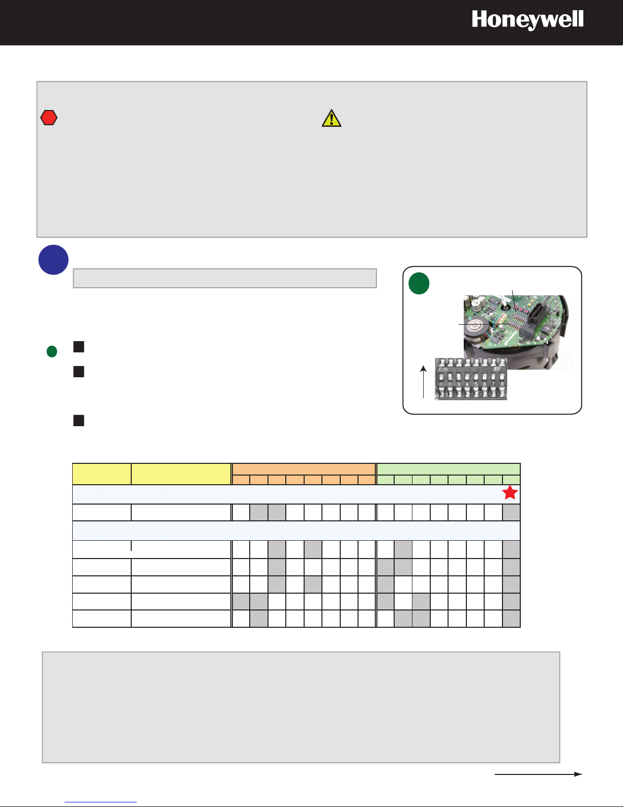
Configure the DIP Switch Settings on the Scan Assembly Circuit Board
1
IntelliBus™ is the recommended protocol for most installations.
To ensure the PTZ dome operates correctly, it is important to
ensure that the pan axis is vertical. In other words, in relation to
the pendant housing, the threaded coupling on the housing
should be vertical, whereas for in-ceiling installations, the flange
of the in-ceiling housing should be horizontal.
Scan Assembly Circuit Board
A
SW5 protocol
Other PTZ protocols are also supported: MAXPRO-mode, VCL-RS485,
Diamond, Pelco P and Pelco D. Depending on your specific system
See
A
installation, protocols other than IntelliBus may need to be configured.
Locate switches SW5 and SW6 on the top of the scan assembly.
1
Set the protocol on switch SW5 in the required positions using
2
the table below. MAXPRO-mode is the default protocol from the
factory.
SW6 baud
rate/parity
ON
DIP Switch
OFF
Set the baud rate and parity on switch SW6 in the required
3
positions using the table below. 9600 baud and even parity are
the defaults from the factory.
Protocol Baud and Parity Description
IntelliBus is the recommended protocol for most installations
IntelliBus 38400 baud, no parity OFF ON ON OFF OFF OFF OFF OFF OFF OFF OFF OFF OFF OFF OFF ON
Optional protocols
MAXPRO-mode* 9600 baud, even parity* OFF OFF ON OFF ON OFF OFF OFF OFF ON OFF OFF OFF OFF OFF ON
VCL - RS485 9600 baud, no parity OFF OFF ON OFF OFF OFF OFF OFF ON ON OFF OFF OFF OFF OFF ON
Diamond 9600 baud, even parity OFF OFF ON OFF ON OFF OFF OFF ON OFF OFF OFF OFF OFF OFF ON
Pelco P 4800 baud, no parity
Pelco D 2400 baud, no parity
* FACTORY DEFAULTS
default for P-type control
default for D-type control
SW6 - Baud and Parity Settings SW5 – Protocol Setting
1234567812345678
ON ON OFF OFF OFF OFF OFF OFF ON OFF ON OFF OFF OFF OFF ON
OFF ON OFF OFF OFF OFF OFF OFF OFF ON ON OFF OFF OFF OFF ON
To learn more about the IP Utility and how to use the ACUIX IP Web-Client to configure
your dome and view live video, open the full ACUIX IP Installation and Configuration
Where Do I Find
More Information?
guide installed on your computer:
Click Start > All Programs > Honeywell Video Systems > EQUIP Series > Manuals
Or you can go to the Honeywell Video website to check for updates:
https://www.honeywellvideo.com/products/cameras/pt/212587.html
Leave
SW5-8 ON
800-01115 Rev B (07-2009)
Indoor pendant and in-ceiling: Ensure a 24 VAC @ 2.0 A power source is available.
Outdoor pendant and rugged: Ensure a 24 VAC @ 2.6 A power source is available.
2
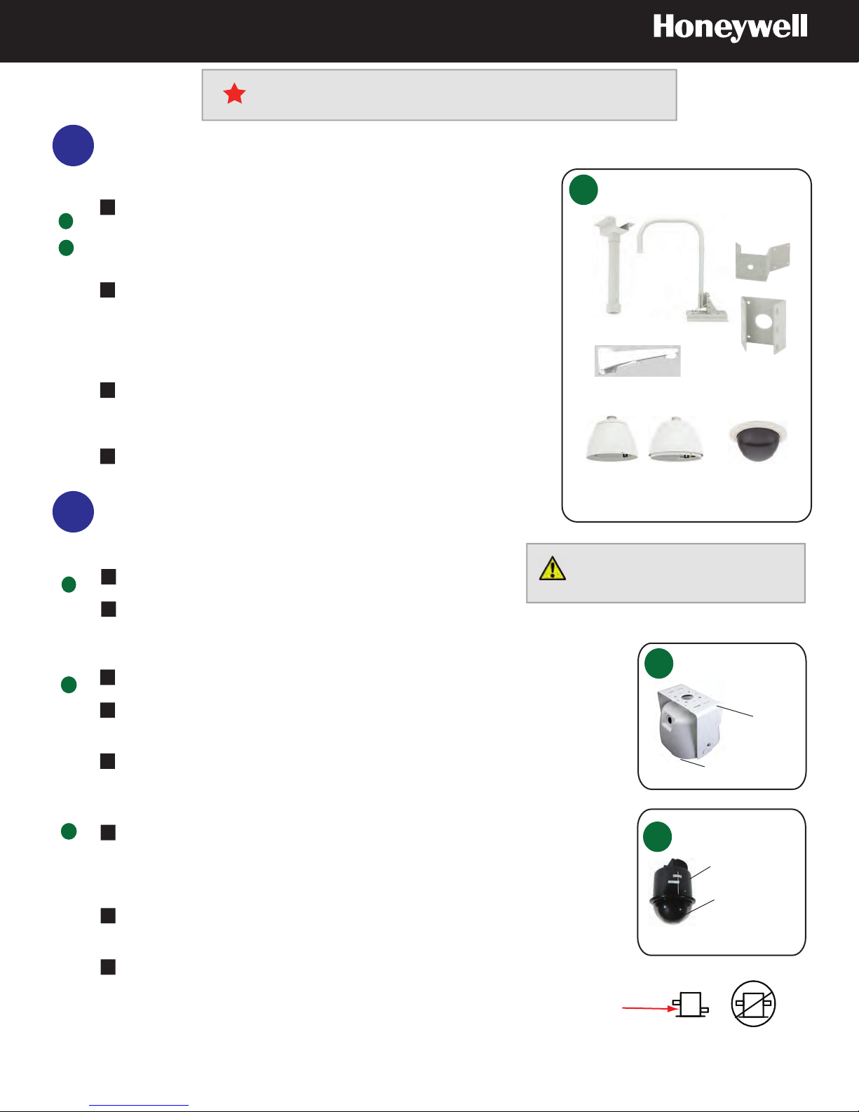
Install the Mount, Adapter or Bracket
Pendant and Rugged Installations Only
See
B
C
Use the hole pattern on the mount, adapter or bracket to drill holes
1
in the wall, ceiling or roof. Use the appropriate hardware for the
mounting surface and follow all installation warnings and cautions
on the first page.
To prevent water leakage with outdoor installations, apply sealant
2
to around all the holes between the mount, mount and the adapter,
and any mounting surface. For wall mount installations also
confirm that the pre-installed gasket on the base of the mount is in
place.
For rugged domes, the bracket can be installed at any angle from
3
0° to 90° with respect to the housing; ensure the housing itself is
positioned horizontally and parallel to the floor.
4
If required for rugged dome installations, secure an installer
supplied safety cable to a building support. A 3/32” (2.5 mm)
plastic coated aircraft cable is recommended.
3
Install the Housing
Indoor and Outdoor Pendant
See
B
Route field wiring from mount through top of housing.
1
2
To prevent threads from binding, wrap the threaded nipple with
Teflon® tape. Thread housing onto mount.
Indoor and Outdoor Pendant
B
Mounts and Adapters
Pole adapter *
Parapet or
roof mount
Ceiling mount
(indoor only)
Wall mount
Corner adapter *
Housing and Lower Dome
Indoor
Outdoor
Lower dome
* The corner and pole adapters can be used with
the pendant wall mount or the rugged bracket
The new V2 pendant housings and
lower dome models MUST be
installed with each other.
Rugged
Install a 0.75” (19 mm) conduit fitting on the housing.
1
C
2
Place the gasket between the hole and the conduit fitting. Tighten the conduit
nut and ensure water tight.
Route the field wiring through the hole in the side of the housing. Secure the
3
housing to the mounting bracket.
In-ceiling (Dropped or Hard Ceiling)
D
Cut a 7 5/8” (194 mm) hole in ceiling using the template provided. Seal
1
perimeter to stop dust or debris from falling from ceiling. For dropped ceilings,
remove ceiling plate and place on dropped ceiling tile. Trim the tile and press
into the plate.
If required, secure an installer supplied safety cable to a building support. A
2
3/32” (2.5 mm) plastic coated aircraft cable is recommended.
Place tile (including the plate for dropped ceilings, part number 517082-7130)
3
and housing on the ceiling grid supports.
Rotate tabs clockwise to tighten against ceiling. Ensure the space between wing
tab and housing is greater than ceiling thickness, and the wing tabs are staggered
to different heights.
Insert through hole with wing tabs flat.
Rugged Dome Housing
C
with Mounting Bracket
Mounting bracket
(included with
housing)
Housing
In-Ceiling Housing*
D
Indoor in-ceiling
housing
Lower dome
*For a dropped ceiling
use a ceiling plate
2
800-01115 Rev B (07-2009)
 Loading...