

Honeywell Equip 720p, HCD5MIH, HCD5MIHX Reference Manual

®
EQUIP
Series 720p
True Day/Night Network
Box Camera
NTSC / PAL
HCD5MIH HCD5MIHX
Reference Guide
Document 800-07067 – Rev C – 11/10


Reference Guide

Revisions
Issue Date Revisions
A 07/10 New document for HCD5MIH/X release. Generally describes the functionality of the
firmware of the Honeywell Color Day/Night Network Camera.
B 10/10 Added correct screen shots and the correct content for SnapShot and Rebooting
cameras.
C 11/10 Corrected the description of the Compression Settings; added an explanation of PSIA
compliance; updated the Web-Client screenshots; added explanations of ELC and
PoE to the glossary.
4

Contents
Figures. . . . . . . . . . . . . . . . . . . . . . . . . . . . . . . . . . . . . . . . . . . . . . . . . . 7
Tables . . . . . . . . . . . . . . . . . . . . . . . . . . . . . . . . . . . . . . . . . . . . . . . . . . 9
About This Document . . . . . . . . . . . . . . . . . . . . . . . . . . . . . . . . . . . . . . . . . 11
Overview of Contents. . . . . . . . . . . . . . . . . . . . . . . . . . . . . . . . . . . . . . . . . . . 11
Cautions and Warnings . . . . . . . . . . . . . . . . . . . . . . . . . . . . . . . . . . . . . . . . . 12
FCC Compliance Statement . . . . . . . . . . . . . . . . . . . . . . . . . . . . . . . . . . . . . . . 12
Manufacturer’s Declaration of Conformance. . . . . . . . . . . . . . . . . . . . . . . . . . . . . . . 13
North America. . . . . . . . . . . . . . . . . . . . . . . . . . . . . . . . . . . . . . . . . . . 13
Europe . . . . . . . . . . . . . . . . . . . . . . . . . . . . . . . . . . . . . . . . . . . . . . 13
Warranty and Service. . . . . . . . . . . . . . . . . . . . . . . . . . . . . . . . . . . . . . . . . . . 13
HCD5MIH/X 720p True Day/Night Network Box Camera Reference Guide
1 Introduction . . . . . . . . . . . . . . . . . . . . . . . . . . . . . . . . . . . . . . . . . . . . . . 15
Features . . . . . . . . . . . . . . . . . . . . . . . . . . . . . . . . . . . . . . . . . . . . . . . . . 16
2 Installation and Setup. . . . . . . . . . . . . . . . . . . . . . . . . . . . . . . . . . . . . . . . . 17
Before you Begin . . . . . . . . . . . . . . . . . . . . . . . . . . . . . . . . . . . . . . . . . . . . . . 17
Unpack Everything . . . . . . . . . . . . . . . . . . . . . . . . . . . . . . . . . . . . . . . . 17
Overview of the Installation Procedure . . . . . . . . . . . . . . . . . . . . . . . . . . . . . . . . . . . 18
Installation . . . . . . . . . . . . . . . . . . . . . . . . . . . . . . . . . . . . . . . . . . . . . . . . . 18
Selecting the Lens . . . . . . . . . . . . . . . . . . . . . . . . . . . . . . . . . . . . . . . . 18
Adjusting the Back Focus . . . . . . . . . . . . . . . . . . . . . . . . . . . . . . . . . . . . 19
Mounting the Camera. . . . . . . . . . . . . . . . . . . . . . . . . . . . . . . . . . . . . . .19
Wiring . . . . . . . . . . . . . . . . . . . . . . . . . . . . . . . . . . . . . . . . . . . . . . . . . . . . 20
Connecting Video. . . . . . . . . . . . . . . . . . . . . . . . . . . . . . . . . . . . . . . . . 20
Connecting Power . . . . . . . . . . . . . . . . . . . . . . . . . . . . . . . . . . . . . . . . 21
Connecting Alarms . . . . . . . . . . . . . . . . . . . . . . . . . . . . . . . . . . . . . . . . 22
Connecting Audio. . . . . . . . . . . . . . . . . . . . . . . . . . . . . . . . . . . . . . . . . 24
Restoring Factory Defaults . . . . . . . . . . . . . . . . . . . . . . . . . . . . . . . . . . . . 24
3 Installing the Honeywell IP Utility and Web-Client Software . . . . . . . . . . . . . . . . . . . . 25
About the Honeywell IP Utility and Web-Client. . . . . . . . . . . . . . . . . . . . . . . . . . . . . . . 25
About the Honeywell IP Utility . . . . . . . . . . . . . . . . . . . . . . . . . . . . . . . . . . 25
About the Web-Client . . . . . . . . . . . . . . . . . . . . . . . . . . . . . . . . . . . . . . . 26
User Profiles: Honeywell IP Utility and Web-Client . . . . . . . . . . . . . . . . . . . . . . . . 26
Step 1: Confirm Your System Requirements. . . . . . . . . . . . . . . . . . . . . . . . . . . . . . . . 27
Step 2: Install the Honeywell IP Utility Software . . . . . . . . . . . . . . . . . . . . . . . . . . . . . . 28
Downloading the EQUIP Series Installation Guides . . . . . . . . . . . . . . . . . . . . . . . 28
Step 3: Log Onto the IP Utility and Discover Network Devices . . . . . . . . . . . . . . . . . . . . . . 29
Step 4: Connect to a Device and Configure Network Settings . . . . . . . . . . . . . . . . . . . . . . 31
Connecting to or Disconnecting from Devices . . . . . . . . . . . . . . . . . . . . . . . . . . 31
Configuring the IP Network Settings Automatically or Manually . . . . . . . . . . . . . . . . . 31
Interfacing with the EQUIP PSIA Device Via a Network Video Recorder . . . . . . . . . . . . 34
Document 800-07067 Rev C 5
11/10

Contents
Step 5: Launch the Web-Client to View Live Video . . . . . . . . . . . . . . . . . . . . . . . . . . . .34
Uninstalling IP Utility, Bonjour or the ActiveX Plug-in Software . . . . . . . . . . . . . . . . . . . . . .36
Uninstalling IP Utility Using the Start Menu . . . . . . . . . . . . . . . . . . . . . . . . . . . 36
Uninstalling IP Utility or IP ActiveX Using the Control Panel . . . . . . . . . . . . . . . . . . . 37
4 IP Camera Web-Client . . . . . . . . . . . . . . . . . . . . . . . . . . . . . . . . . . . . . . . . 39
Overview . . . . . . . . . . . . . . . . . . . . . . . . . . . . . . . . . . . . . . . . . . . . . . . . . . 39
User Profiles . . . . . . . . . . . . . . . . . . . . . . . . . . . . . . . . . . . . . . . . . . . 40
Logging On and Off the IP Web-Client . . . . . . . . . . . . . . . . . . . . . . . . . . . . . . . . . . . 40
Launching the Web-Client from IP Utility . . . . . . . . . . . . . . . . . . . . . . . . . . . . . 41
Logging Onto the Web-Client from Internet Explorer . . . . . . . . . . . . . . . . . . . . . . 42
Logging Out of the Web-Client . . . . . . . . . . . . . . . . . . . . . . . . . . . . . . . . . . 42
Navigating the Web-Client User Interface . . . . . . . . . . . . . . . . . . . . . . . . . . . . . . . . . 43
Live View . . . . . . . . . . . . . . . . . . . . . . . . . . . . . . . . . . . . . . . . . . . . . . . . . . 44
Taking a SnapShot . . . . . . . . . . . . . . . . . . . . . . . . . . . . . . . . . . . . . . . . 45
Device Settings . . . . . . . . . . . . . . . . . . . . . . . . . . . . . . . . . . . . . . . . . . . . . . . 45
Configuring IP and Firmware Settings . . . . . . . . . . . . . . . . . . . . . . . . . . . . . . 45
Resetting the Device . . . . . . . . . . . . . . . . . . . . . . . . . . . . . . . . . . . . . . . 46
Compression Settings . . . . . . . . . . . . . . . . . . . . . . . . . . . . . . . . . . . . . . . . . . . 47
Video Codec Settings Tab . . . . . . . . . . . . . . . . . . . . . . . . . . . . . . . . . . . . 48
Statistics: Received Bit Rate and Frame Rate . . . . . . . . . . . . . . . . . . . . . . . . . . 50
Camera Setup . . . . . . . . . . . . . . . . . . . . . . . . . . . . . . . . . . . . . . . . . . . . . . . 50
Auto Exposure . . . . . . . . . . . . . . . . . . . . . . . . . . . . . . . . . . . . . . . . . . 51
White Balance. . . . . . . . . . . . . . . . . . . . . . . . . . . . . . . . . . . . . . . . . . . 52
Video Analytics . . . . . . . . . . . . . . . . . . . . . . . . . . . . . . . . . . . . . . . . . . . . . . . 53
Sabotage Detection. . . . . . . . . . . . . . . . . . . . . . . . . . . . . . . . . . . . . . . . 54
Configuring Video Motion Detection . . . . . . . . . . . . . . . . . . . . . . . . . . . . . . . 57
Alarm and Audio . . . . . . . . . . . . . . . . . . . . . . . . . . . . . . . . . . . . . . . . . . . . . . 58
Alarm Settings . . . . . . . . . . . . . . . . . . . . . . . . . . . . . . . . . . . . . . . . . . 58
Audio Settings . . . . . . . . . . . . . . . . . . . . . . . . . . . . . . . . . . . . . . . . . .59
Appendix A Troubleshooting . . . . . . . . . . . . . . . . . . . . . . . . . . . . . . . . . . . . . 61
Technical Support . . . . . . . . . . . . . . . . . . . . . . . . . . . . . . . . . . . . . . . . . . . . . 61
Problem: Web-Client Does Not Display the Expected Video . . . . . . . . . . . . . . . . . . . . . . . 61
Problem: Cannot Connect to a Device. . . . . . . . . . . . . . . . . . . . . . . . . . . . . . . . . . . 62
Appendix B Specifications . . . . . . . . . . . . . . . . . . . . . . . . . . . . . . . . . . . . . . 63
Appendix C Glossary . . . . . . . . . . . . . . . . . . . . . . . . . . . . . . . . . . . . . . . . . 67
Index . . . . . . . . . . . . . . . . . . . . . . . . . . . . . . . . . . . . . . . . . . . . . . . . . . . . . 69
6

HCD5MIH/X 720p True Day/Night Network Box Camera Reference Guide
Figures
Figure 1-1 Camera Overview . . . . . . . . . . . . . . . . . . . . . . . . . . . . . . . . . . . . . . . 15
Figure 2-1 Back Focus Adjustment . . . . . . . . . . . . . . . . . . . . . . . . . . . . . . . . . . . . 19
Figure 2-2 Camera Mount . . . . . . . . . . . . . . . . . . . . . . . . . . . . . . . . . . . . . . . . . 20
Figure 2-3 Camera Connections . . . . . . . . . . . . . . . . . . . . . . . . . . . . . . . . . . . . . 20
Figure 2-4 Alarm Connections . . . . . . . . . . . . . . . . . . . . . . . . . . . . . . . . . . . . . . 23
Figure 2-5 Normal Alarm States . . . . . . . . . . . . . . . . . . . . . . . . . . . . . . . . . . . . . . 23
Figure 2-6 Alarm Output Connection . . . . . . . . . . . . . . . . . . . . . . . . . . . . . . . . . . . 24
Figure 3-1 Accessing Your Installation Documents. . . . . . . . . . . . . . . . . . . . . . . . . . . . 28
Figure 3-2 Honeywell IP Utility Log On Window . . . . . . . . . . . . . . . . . . . . . . . . . . . . . 29
Figure 3-3 Honeywell IP Utility User Interface. . . . . . . . . . . . . . . . . . . . . . . . . . . . . . . 30
Figure 3-4 Setting the IP Network Settings Automatically or Manually . . . . . . . . . . . . . . . . . . 32
Figure 3-5 ActiveX Prompt. . . . . . . . . . . . . . . . . . . . . . . . . . . . . . . . . . . . . . . . . 35
Figure 3-6 Web-Client Interface After Logging On . . . . . . . . . . . . . . . . . . . . . . . . . . . . 36
Figure 4-1 Launching the Web-Client from the IP Utility . . . . . . . . . . . . . . . . . . . . . . . . . 41
Figure 4-2 Web-Client Window Layout: Administrator Log On . . . . . . . . . . . . . . . . . . . . . . 43
Figure 4-3 Web-Client: Administrator User . . . . . . . . . . . . . . . . . . . . . . . . . . . . . . . . 44
Figure 4-4 Web-Client: Guest User . . . . . . . . . . . . . . . . . . . . . . . . . . . . . . . . . . . . 44
Figure 4-5 Device Settings . . . . . . . . . . . . . . . . . . . . . . . . . . . . . . . . . . . . . . . . 45
Figure 4-6 IP and Firmware Settings: Device Information Tab . . . . . . . . . . . . . . . . . . . . . . 46
Figure 4-7 Compressions Settings Tab: Primary Stream . . . . . . . . . . . . . . . . . . . . . . . . . 47
Figure 4-8 Video Codec Settings Tab Available Functions . . . . . . . . . . . . . . . . . . . . . . . 48
Figure 4-9 Video Codec Settings . . . . . . . . . . . . . . . . . . . . . . . . . . . . . . . . . . . . . 49
Figure 4-10 Camera Setup . . . . . . . . . . . . . . . . . . . . . . . . . . . . . . . . . . . . . . . . . 51
Figure 4-11 Video Analytics Tab . . . . . . . . . . . . . . . . . . . . . . . . . . . . . . . . . . . . . . 54
Figure 4-12 Tamper Detection Settings on the Video Analytics Tab. . . . . . . . . . . . . . . . . . . . 54
Figure 4-13 Video Analytics Alarm Message . . . . . . . . . . . . . . . . . . . . . . . . . . . . . . . . 55
Figure 4-14 Video Analytics: Defining a Region . . . . . . . . . . . . . . . . . . . . . . . . . . . . . . 57
Figure 4-15 Audio and IO Settings Tab. . . . . . . . . . . . . . . . . . . . . . . . . . . . . . . . . . . 58
Figure 4-16 Audio Settings . . . . . . . . . . . . . . . . . . . . . . . . . . . . . . . . . . . . . . . . . 59
Figure A-1 Limited or No Connection Message . . . . . . . . . . . . . . . . . . . . . . . . . . . . . . 62
Figure B-1 Camera Dimensions . . . . . . . . . . . . . . . . . . . . . . . . . . . . . . . . . . . . . . 65
Document 800-07067 Rev C 7
11/10

Figures
8

HCD5MIH/X 720p True Day/Night Network Box Camera Reference Guide
Tables
Table 1-1 Network Camera Model Numbers . . . . . . . . . . . . . . . . . . . . . . . . . . . . . . . 15
Table 3-1 User Profiles for Honeywell IP Utility and the Web-Client . . . . . . . . . . . . . . . . . . . 26
Table 3-2 PC Minimum System Requirements . . . . . . . . . . . . . . . . . . . . . . . . . . . . . . 27
Table 3-3 Items Installed On Your System . . . . . . . . . . . . . . . . . . . . . . . . . . . . . . . . 27
Table 3-4 IP Network Device Setting Options . . . . . . . . . . . . . . . . . . . . . . . . . . . . . . . 32
Table 4-1 User Roles and Privileges . . . . . . . . . . . . . . . . . . . . . . . . . . . . . . . . . . . 40
Table 4-2 Tabs/Views in the Web-Client Application . . . . . . . . . . . . . . . . . . . . . . . . . . . 43
Table 4-3 Video Streaming Resolutions . . . . . . . . . . . . . . . . . . . . . . . . . . . . . . . . . . 48
Table 4-4 Compression Settings . . . . . . . . . . . . . . . . . . . . . . . . . . . . . . . . . . . . . 48
Table 4-5 Auto Exposure Settings. . . . . . . . . . . . . . . . . . . . . . . . . . . . . . . . . . . . . 51
Table 4-6 White Balance Settings . . . . . . . . . . . . . . . . . . . . . . . . . . . . . . . . . . . . . 53
Table 4-7 Blur Threshold Values . . . . . . . . . . . . . . . . . . . . . . . . . . . . . . . . . . . . . 55
Table 4-8 Blinding Threshold Values . . . . . . . . . . . . . . . . . . . . . . . . . . . . . . . . . . . 56
Table 4-9 Scene Change Threshold Values . . . . . . . . . . . . . . . . . . . . . . . . . . . . . . . 56
Document 800-07067 Rev C 9
11/10

Tables
10

HCD5MIH/X 720p True Day/Night Network Box Camera Reference Guide
About This Document
This document introduces the Honeywell HCD5MIH/X High Resolution True Day/Night
Network Box Camera. It covers how to install, configure and operate the camera in a
network environment. This document is intended for system installers, administrators,
and operators.
Overview of Contents
This document contains the following chapters and appendixes:
• Chapter 1, Introduction, introduces the Honeywell network box camera and gives a
functional overview of its components.
• Chapter 2, Installation and Setup, provides procedures for installing cameras, lens
adjustment, and setting up a network camera environment.
• Chapter 3, Installing the Honeywell IP Utility and Web-Client Software, describes how
to install and use the Honeywell IP Utility and Web-Client software.
• Chapter 4, IP Camera Web-Client, describes how to use the Web-Client application
to view video and configure the available settings for the network camera.
• Appendix A, Troubleshooting, lists common problems encountered when setting up
the network camera.
• Appendix B, Specifications, provides specifications for the network camera.
• Chapter C, Glossary, explains terms and initializations used in this guide.
•The Index provides quick access to commonly searched terms.
Document 800-07067 Rev C 11
11/10
About This Document
CAUTION: TO REDUCE THE RISK OF
ELECTRIC SHOCK, DO NOT REMOVE
THE COVER. NO USER-SERVICEABLE
PARTS INSIDE. REFER SERVICING TO
QUALIFIED SERVICE PERSONNEL.
THIS SYMBOL INDICATES
THAT IMPORTANT OPERATING
AND MAINTENANCE
INSTRUCTIONS ACCOMPANY
THIS UNIT.
THIS SYMBOL INDICATES
THAT DANGEROUS VOLTAGE
CONSTITUTING A RISK OF
ELECTRIC SHOCK IS
PRESENT WITHIN THE UNIT.
RISK OF
ELECTRIC SHOCK
DO NOT OPEN
CAUTION
Cautions and Warnings
Installation and servicing should be performed only by qualified and experienced
technicians to conform to all local codes and to maintain your warranty.
WARNING! 24 VAC models require the use of CSA Certified/UL Listed
Class 2 power adapters to ensure compliance with
electrical safety standards. Power over Ethernet (PoE)
should meet the IEEE 802.3 af PoE standard.
WEEE (Waste Electrical and Electronic Equipment). Correct disposal of this
product (applicable in the European Union and other European countries with
separate collection systems). This product should be disposed of, at the end of
its useful life, as per applicable local laws, regulations, and procedures.
Caution When powering the camera from 24 VAC, a UPS source should
be considered to ensure satisfactory performance.
FCC Compliance Statement
12
Information to the User: This equipment has been tested and found to comply with the
limits for a Class B digital device. Pursuant to Part 15 of the FCC Rules, these limits are
designed to provide reasonable protection against harmful interference in a residential
installation. This equipment generates, uses, and can radiate radio frequency energy and,

HCD5MIH/X 720p True Day/Night Network Box Camera Reference Guide
if not installed and used in accordance with the instruction manual, may cause harmful
interference to radio communications. However, there is no guarantee that interference
will not occur in a particular installation.
If this equipment does cause harmful interference to radio or television reception, which
can be determined by turning the equipment off and on, the user is encouraged to try to
correct the interference. For example, try reorienting or relocating the receiving antenna,
increasing the separation between the equipment and receiver, or connecting the
equipment to an outlet on a different circuit.
Caution Changes or modifications not expressly approved by the party
responsible for compliance could void the user’s authority to
operate the equipment.
This Class B digital apparatus complies with Canadian ICES-003.
Manufacturer’s Declaration of Conformance
North America
The equipment supplied with this guide conforms to UL 60905-1 and CSA C22.2 No.
60950.
Europe
The manufacturer declares that the equipment supplied with this guide is compliant with
the essential protection requirements of the EMC directive 2004/108/EC and the General
Product Safety Directive 2001/95/EC, conforming to the requirements of standards EN
55022 for emissions, EN 50130-4 for immunity, and EN 60950 for Electrical Equipment
safety.
Warranty and Service
Subject to the terms and conditions listed on the Product warranty, during the warranty
period Honeywell will repair or replace, at its sole option, free of charge, any defective
products returned prepaid.
In the event you have a problem with any Honeywell product, please call Customer
Service at 1.800.796.CCTV for assistance or to request a Return Merchandise
Authorization (RMA) number.
Document 800-07067 Rev C 13
11/10

About This Document
Be sure to ha ve th e mod el n umbe r, se rial number, and the nature of the problem available
for the technical service representative.
Prior authorization must be obtained for all returns, exchanges, or credits. Items shipped
to Honeywell without a clearly identified Return Merchandise Authorization (RMA)
number may be refused.
14
1
Introduction
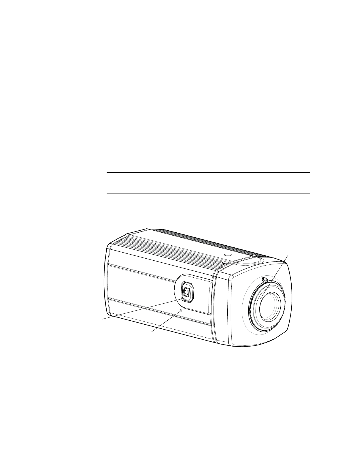
Reset button restores
factory default settings
CS lens mount
Lens connector for
DC Auto Iris lens plug
The Honeywell High Resolution True Day/Night Network Box Camera provides high
picture quality remote video surveillance over a network connection. See Table 1-1 for a
list of camera models.
Model Number Description
HCD5MIH True Day/Night 720p Network Camera, NTSC
HCD5MIHX True Day/Night 720p Network Camera, PAL
Figure 1-1 Camera Overview
Table 1-1 Network Camera Model Numbers
Document 800-07067 Rev C 15
11/10

Introduction
Features
The Honeywell Megapixel IP Box Camera has the following features:
• 720p (1280 x 720) resolution for the HCD5MIH/X models
• 1/4" color CMOS progressive scan sensor
• Moveable Infrared (IR) cut filter ensures excellent low light performance
• Camera Sabotage Detection
• Video Motion Detection
• H.264 and MJPEG compression
• Dual digital video streams simultaneously, independently configurable
• Remote firmware updates
• Support of both Dynamic and Static IP address assignment
• Multiple levels of password-protected remote access prevents unauthorized users
from altering system settings
• Advanced IP locator software to make system setup easy
• Web server for remote setup of camera video and network parameters
• 24 VAC or PoE IEEE 802.3 af choice of power inputs
• Input and output alarm contacts support
• Bi-directional audio support
• Local video out – aim and focus
•PSIA compliant
16

2
Installation and Setup
This chapter describes how to:
•Mount the camera(s)
• Adjust the camera(s) for the clearest image
• Set up cameras in a network system
Before you Begin
Before you install your IP box camera:
• Please read this guide carefully. Keep this guide for future reference.
• Honeywell recommends that you check
www.honeywellvideo.com/products/cameras/ to find your camera and download
the latest manuals and software updates.
Unpack Everything
Check that the items received match those listed on the order form and packing slip. The
packing box should include, in addition to this User Guide:
•One network camera
• 3-pin terminal block for Power input
• 4-pin terminal block for Alarm input/output
• One product warranty
• One CD containing the product software and the User Guide
If any parts are missing or damaged, contact the dealer you purchased the camera from
or call Honeywell Customer Service (see Warranty and Service on page 13).
Document 800-07067 Rev C 17
11/10

Installation and Setup
Overview of the Installation Procedure
This network camera is intended for indoor use only. If you choose to mount the camera
outdoors, you must employ a suitable weatherproof enclosure (such as Honeywell’s
HHC12 camera housing). See www.honeywellvideo.com for information on Honeywell
weatherproof enclosures and mounting brackets.
Note Please familiarize yourself with the installation procedure and complete each
step in the sequence given.
The initial installation of a network camera consists of the following steps:
Step See …
1 Select the lens. page 18
Installation
Selecting the Lens
The network camera supports the use of a manual iris lens or DC (Direct Drive) auto iris
lens. When using a DC auto iris lens, it should be connected to the camera through the
4-pin square socket located at the side of the camera (see Figure 2-1).
If you are disatisfied with the sharpness of the image, then you should ensure that you are
using a megapixel lens. For a list of recommended lenses, go to
www.honeywellvideo.com/products/cameras/.
2 Adjust the back focus. page 19
3 Mount the camera. page 19
4 Connect the camera. page 20
5 Program the camera. page 50
18

HCD5MIH/X 720p True Day/Night Network Box Camera Reference Guide
Setscrews
Reset button restores
factory default settings
Lens connector for
DC auto lris lens
Focus
ring
Adjusting the Back Focus
The back focus adjustment is accessible at the front end of the camera housing to adjust
the back focal length or picture focus.
The range of adjustment allows the CS-mount lenses to be used without the need for a
spacer ring.
Figure 2-1 Back Focus Adjustment
1. Loosen the setscrews with a Phillips screwdriver.
2. Adjust the focus ring at the front end of the camera housing to focus the picture.
3. Re-tighten the setscrews.
Mounting the Camera
Mounting points are provided on the top and bottom of the camera and are used to mount
the camera on a bracket or tripod for indoor applications. They are designed to accept
standard sized mounting bolts (1/4 x 20). The mounting bracket must be capable of
supporting the weight of the camera and its lens.
Caution Some installation codes state that the mounting bracket must be
For outdoor applications, mount the camera inside a weatherproof enclosure. See
www.honeywellvideo.com for information on Honeywell weatherproof enclosures.
capable of supporting up to four times the combined weight of the
camera and lens.
Document 800-07067 Rev C 19
11/10

Installation and Setup
Use standard size
mounting bolts (1/4 x 20)
to mount the camera on
a bracket or tripod.
Analog video connection
for a spot monitor
24 VAC power
Audio line level input and
output connections (600
Ohm impedance).
RJ45 Ethernet network
connection (using
10Base T or 100Base
TX cable). Also for
Power over Ethernet
(PoE 802.3 af).
Alarm input (maximum rated
voltage level 24 VDC) and output.
Contacts rated 12 VDC @ 0.5 A.
Wiring
Figure 2-2 Camera Mount
Caution Installation must be performed by a qualified service technician and
Connecting Video
Figure 2-3 Camera Connections
must be in accordance with all national and local mechanical and
electrical codes.
20
Spot Monitor
The analog video connection is available as a test output and should be used during
installation to aim and focus the camera as needed.
Connect the VIDEO connector on the rear of the camera to the video input connector on
your spot monitor.

Network RJ-45 Ethernet Connection
The main video connection for your network camera will be made through your Ethernet
network connection. Connect the Ethernet connector on the rear of the camera to your
network using an Ethernet (10Base-T, 100Base-TX) cable.
Connecting Power
Caution When connecting a power supply, use a 24 VAC power plug or a PoE
HCD5MIH/X 720p True Day/Night Network Box Camera Reference Guide
Note You can connect your camera to a network or connect it directly to a PC or
laptop using a crossover cable.
IEEE 802.3 (Power over Ethernet) compatible hub. To avoid damage
to the camera, never connect more than one type of power supply at
the same time.
WARNING! The use of a CSA Certified/UL Listed Class 2 power supply is
required to ensure compliance with electrical safety
standards.
Note Check the power source from the external power supply before applying
power to the camera.
1. Connect the camera to a power supply appropriate for your installation:
• 24 VAC power supply (proceed to step 2)
• Power over Ethernet (PoE IEEE 802.3 af) 48 VDC power supply
Note If you are using PoE (802.3 af), power will automatically be supplied to the
camera through the network cable.
2. Plug in the power supply. Use a screwdriver to first loosen the ~AC24V terminal
screws on the terminal block.
Document 800-07067 Rev C 21
11/10

Installation and Setup
Note To ease installation, the terminal block can be removed. The power
connections of the removable terminal block are not polarity-sensitive.
Connect either power lead to either connector terminal.
3. Secure the power leads by tightening the terminal screws until snug.
4. Plug the power supply into an appropriate power source.
Note For secure installations, surface-mounted cables should be protected by
plastic or metal cable covers.
Note If your installation involves a 24V AC power source, then please wait
approximately 60 seconds after connecting to a power source for video to
appear on the local video out.
Caution Installation must be performed by a qualified service technician. The
Caution When powering the camera from 24 VAC, a UPS source should be
Caution Connect power either from a 24 VAC source or CAT5 Ethernet
Connecting Alarms
WARNING! Do not exceed the maximum rating of 12 VDC, 0.5 A on alarm
proper wire gauge for the distance and number of cameras must be
determined to maintain 24 VAC at each camera.
considered to ensure satisfactory performance.
connector (PoE); never both at the same time.
output connections.
22

HCD5MIH/X 720p True Day/Night Network Box Camera Reference Guide
IN
OUT
IN
OUT
ALARM
Normally closed
Normally opened
The network camera has one alarm input and one alarm output available to connect to
peripheral devices (Figure 2-4).
Figure 2-4 Alarm Connections
Connect mechanical or electrical switches to the alarm input connection to allow
event-triggered recording. When alarm inputs are configured, the camera triggers an alarm
only when the normal state (open or closed) changes (see Figure 2-5). See Alarm Settings
on page 58 to configure the alarm inputs.
The network camera has a LAMP setting which allows control of the moving IR cut filter
when there is a change in state from Normally Open to Normally Closed (see Alarm Settings
on page 58 for more information). In this way, the moving IR cut filter and the day/night
operation of the camera can be synchronized with external lighting changes using a
common controller such as a photocell or timer.
Figure 2-5 Normal Alarm States
Connect external devices such as sirens or flashing lights to the alarm output connector to
signal users of the camera that an alarm is activated. See Figure 2-6 for alarm connection.
Document 800-07067 Rev C 23
11/10
 Loading...