

Page 1

Experion PKS
Release 516
Honeywell FSC Integration Reference
EPDOC-XX56-en-516A
August 2020
Page 2

DISCLAIMER
This document contains Honeywell proprietary information.
Information contained herein is to be used solely for the purpose
submitted, and no part of this document or its contents shall be
reproduced, published, or disclosed to a third party without the
express permission of Honeywell International Sàrl.
While this information is presented in good faith and believed to be
accurate, Honeywell disclaims the implied warranties of
merchantability and fitness for a purpose and makes no express
warranties except as may be stated in its written agreement with and
for its customer.
In no event is Honeywell liable to anyone for any direct, special, or
consequential damages. The information and specifications in this
document are subject to change without notice.
Copyright 2020 - Honeywell International Sàrl
2
Page 3

CONTENTS
Contents 3
Chapter 1 - Planning considerations for Honeywell FSC controllers 5
Devices supported by the Honeywell FSC interface 6
Other documentation for Honeywell FSC 7
FSC-specific terms 7
Differences between serial and Ethernet controllers 8
Architectures for Honeywell FSC 8
Serial connections for Honeywell FSC 8
Ethernet connections for Honeywell FSC 11
Contents
Communication settings for Honeywell FSC 13
Serial connection settings for Honeywell FSC 13
Ethernet connection settings for Honeywell FSC 14
Assigning SER numbers for sequence of events 15
Reserved SER numbers 16
Interpreting SOE lines 17
Chapter 2 - Honeywell FSC channel and controller reference 19
Main properties for a Honeywell FSC channel 20
Port properties for a Honeywell FSC channel 22
Main properties for a Honeywell FSC controller 25
About time synchronization on Honeywell FSC controllers 28
Optimizing Honeywell FSC scanning performance 29
Chapter 3 - Honeywell FSC points reference 31
Defining a Honeywell FSC address for a point parameter 32
Chapter 4 - Troubleshooting Honeywell FSC issues 37
Accessing diagnostics for an Ethernet controller 38
3
Page 4

Contents
Testing Honeywell FSC communications with the server 38
Troubleshooting Honeywell FSC communication errors for a serial
controller 41
Troubleshooting Honeywell FSC communication errors for an
Ethernet controller 41
Notices 43
4
Page 5

CHAPTER
PLANNING CONSIDERATIONS FOR
1
HONEYWELL FSC CONTROLLERS
This reference provides the information you need to set up, configure,
and test FSC controller communications with the server.
Revision history
Revision Date Description
A August 2020 Initial release of document.
How to use this guide
These are the steps for connecting and configuring a Honeywell FSC
controller. Complete each step before commencing the next.
Steps Go to
Determine FSC configuration Architectures for Honeywell FSC
Setting up the communications
parameters using the FSC configuration
software
Use FSC configuration software to set SER
numbers
Use Quick Builder to define channels
Use Quick Builder to define controllers
Download channel and controller
definitions to the server
Communication settings for Honeywell
FSC
Assigning SER numbers for sequence of
events
l Honeywell FSC channel and
controller reference
l "Build channels" topic in the Quick
Builder User’s Guide
l Honeywell FSC channel and
controller reference
l "Build controllers" topic in the
Quick Builder User’s Guide
"Downloading items" topic in the Quick
Builder User’s Guide
5
Page 6
Chapter 1 - Planning considerations for Honeywell FSC controllers
Steps Go to
Test communications Testing Honeywell FSC
communications with the server
Troubleshooting communication errors Troubleshooting Honeywell FSC
communication errors for a serial
controller
Use Quick Builder to define points Defining a Honeywell FSC address for a
point parameter
Devices supported by the Honeywell FSC interface
The server supports serial and Ethernet FSC controllers.
The server communicates with:
n Serial controllers using a point-to-point or multi-drop RS-232 link
and FSC Modbus protocol
n Ethernet controllers using a proprietary protocol based on the
Modbus protocol
Serial devices supported by the Honeywell FSC
interface
The server supports the following serial FSC controller configurations:
FSC-100 A single rack.
FSC-100R Two identical racks. Basically parallel FSC-100 configuration.
FSC-101 May consist of several racks.
FSC-102 Two Central parts and single I/O.
FSC-101R Two Central parts and redundant I/O.
FSC-202 Two Central racks and redundant I/O.
6
Page 7

Chapter 1 - Planning considerations for Honeywell FSC controllers
Ethernet devices supported by the Honeywell FSC
interface
The server supports the following Ethernet FSC controller
configurations.
FSC1oo1D
FSC1oo1D
FSC1oo2D
Single Central Part with single Ethernet connection
Single Central Part with redundant Ethernet connection
Redundant Central Parts with single Ethernet connection to each
Central Part
Other documentation for Honeywell FSC
This reference provides only supplemental information to interface
FSC controllers with the server. For detailed information about
installing and configuring FSC controllers, see the manufacturer's
documentation.
FSC-specific terms
FSC
Fail-safe controller.
SER
SER channel
SOE
BaseSER Number
Sequence of events recorder.
An FSC setting required so that the server can extract SOE data from
the controller. The server uses the SER channel to poll for SOE data.
Sequence of events.
The unique ID assigned to a serial (non-Ethernet) controller so that
the server can extract SOE data from that controller.
7
Page 8

Chapter 1 - Planning considerations for Honeywell FSC controllers
Differences between serial and Ethernet controllers
The server supports serial and Ethernet FSC controllers. However,
these two controller types are different, and following differences
apply:
n Serial controllers use Modbus; whereas Ethernet controllers use a
proprietary protocol based on Modbus.
n The diagnostic scan rate is not configurable in Ethernet
controllers.
n The Base SER is not required for Ethernet controllers.
n There is a separate test utility for each type of controller.
n System Information and Extended Diagnostics are available for
Ethernet controllers.
Architectures for Honeywell FSC
Honeywell FSC interface supports connection to the server via serial
or Ethernet connection.
Serial connections for Honeywell FSC
The server communicates with serial controllers using a point-topoint or multi-drop RS-232 link and FSC Modbus protocol.
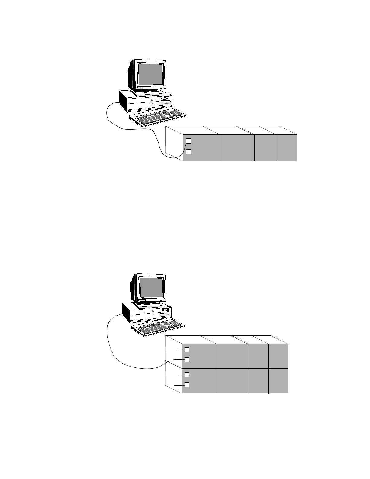
Point-to-point configuration
A point-to-point configuration consists of a controller with a single
COM module connected to a port on the server through a serial link.
Figure 1-1: Point-to-point configuration
8
Page 9
FSC Controller
Server
Central part 1
Server
FSC Controller
Central part 1
Central part 2
Chapter 1 - Planning considerations for Honeywell FSC controllers
Multi-drop configuration
A multi-drop configuration consists of a redundant FSC controller
with two COM modules connected on the same serial link which
connects to a single port on the server.
Note that this type of configuration does not constitute server
communications redundancy, but it does provide a means of talking
to a redundant FSC system across a single channel.
Figure 1-2: Multi-drop configuration
9
Page 10
FSC “Master” Controller
Server
Central part 1
FSC Network - Slave and/or Master Controllers
Chapter 1 - Planning considerations for Honeywell FSC controllers
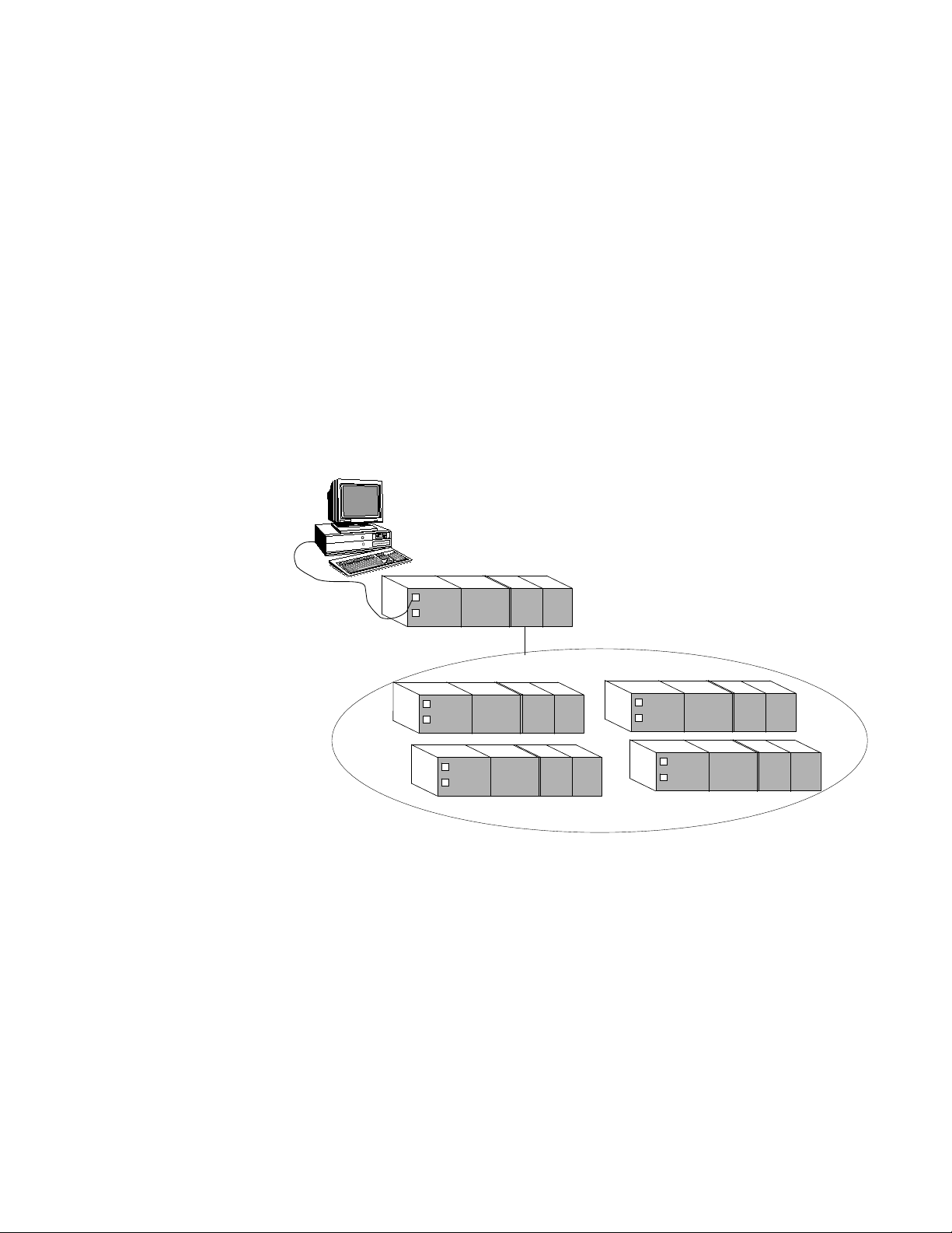
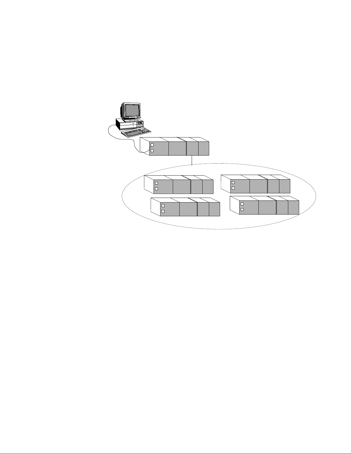
FSC network configuration
Using an FSC network configuration, a single FSC controller manages
the data that the server requests or controls. One controller,
designated as a 'master' controller, is responsible for gathering SOE
data from the FSC network. This enables SOE data from any
networked controller to be obtained from the master controller.
A master controller is also useful for time synchronization. The master
controller is responsible for time synchronization on the FSC
network—synchronizing the time on the master controller also
synchronizes the time on 'slave' controllers. See the topic titled "About
time synchronization on Honeywell FSC controllers" for more
information.
Figure 1-3: FSC network
10
Redundancy for serial controllers
Serial FSC controllers support communication redundancy. This is
not the same as the multi-drop configuration. Communication
redundancy involves a separate physical connection to communicate
with the FSC controller.
Page 11
FSC Controller
Server
Central part 1
Chapter 1 - Planning considerations for Honeywell FSC controllers
Ethernet connections for Honeywell FSC
The server communicates with Ethernet controllers using a
proprietary protocol based on the Modbus protocol. Process data
connections to the FSC are made on TCP port 51000. Information
scan connections to the FSC are made on TCP port 51001.
ATTENTION: Connecting or configuring a single FSC Ethernet
controller to multiple servers is not a supported configuration.
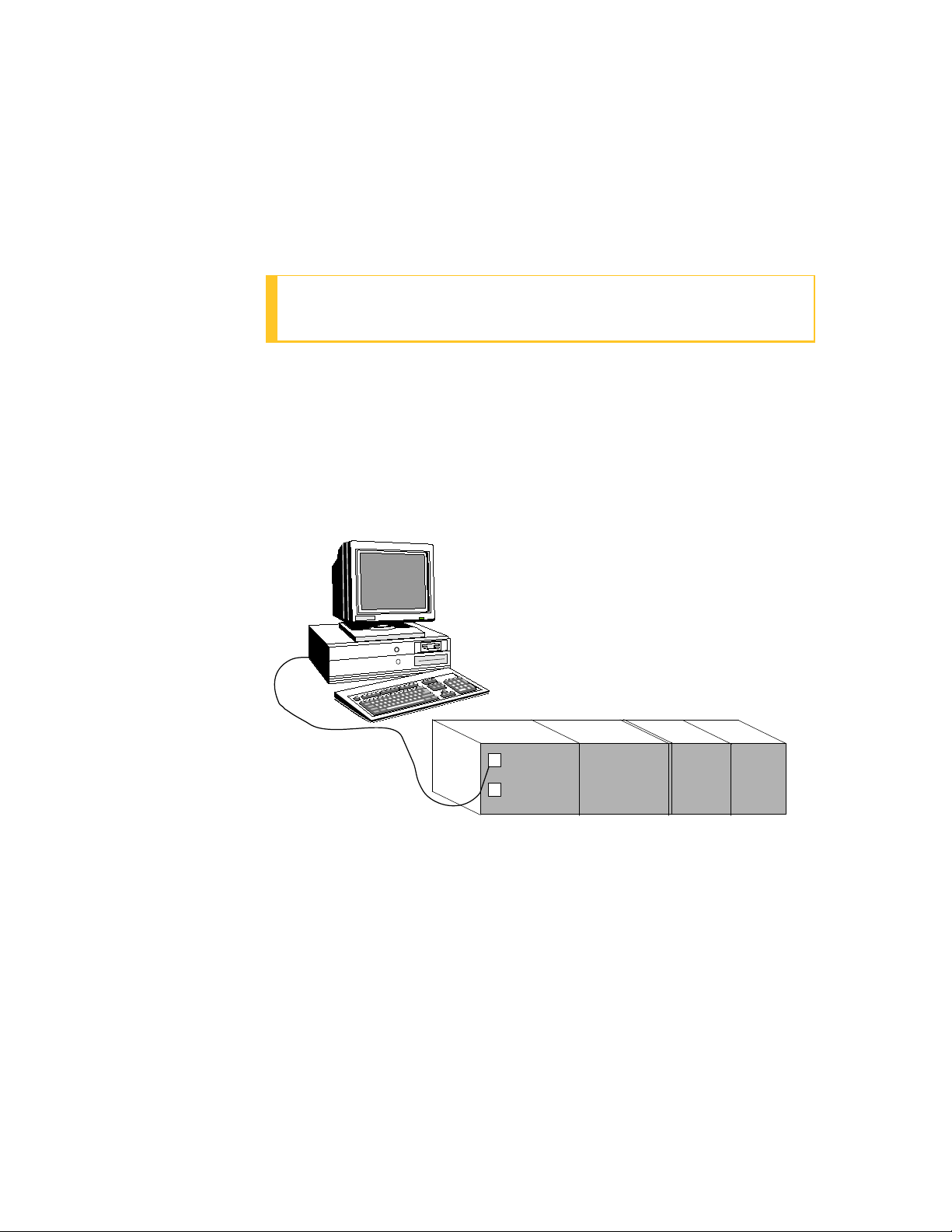
Point-to-point configuration
A point-to-point configuration consists of a controller with a single
COM module connected to a port on the server through an Ethernet
link.
Figure 1-4: Point-to-point configuration
FSC network configuration
Using an FSC network configuration, a single FSC controller manages
the data that the server requests or controls. One controller,
designated as a 'master' controller, is responsible for gathering SOE
data from the FSC network. This enables SOE data from any
networked controller to be obtained from the master controller.
A master controller is also useful for time synchronization. The master
controller is responsible for time synchronization on the FSC
11
Page 12
FSC “Master” Controller
Server
Central part 1
FSC Network - Slave and/or Master Controllers
Chapter 1 - Planning considerations for Honeywell FSC controllers
network—synchronizing the time on the master controller also
synchronizes the time on slave controllers. See the topic titled "About
time synchronization on Honeywell FSC controllers" for more
information.
Figure 1-5: FSC network
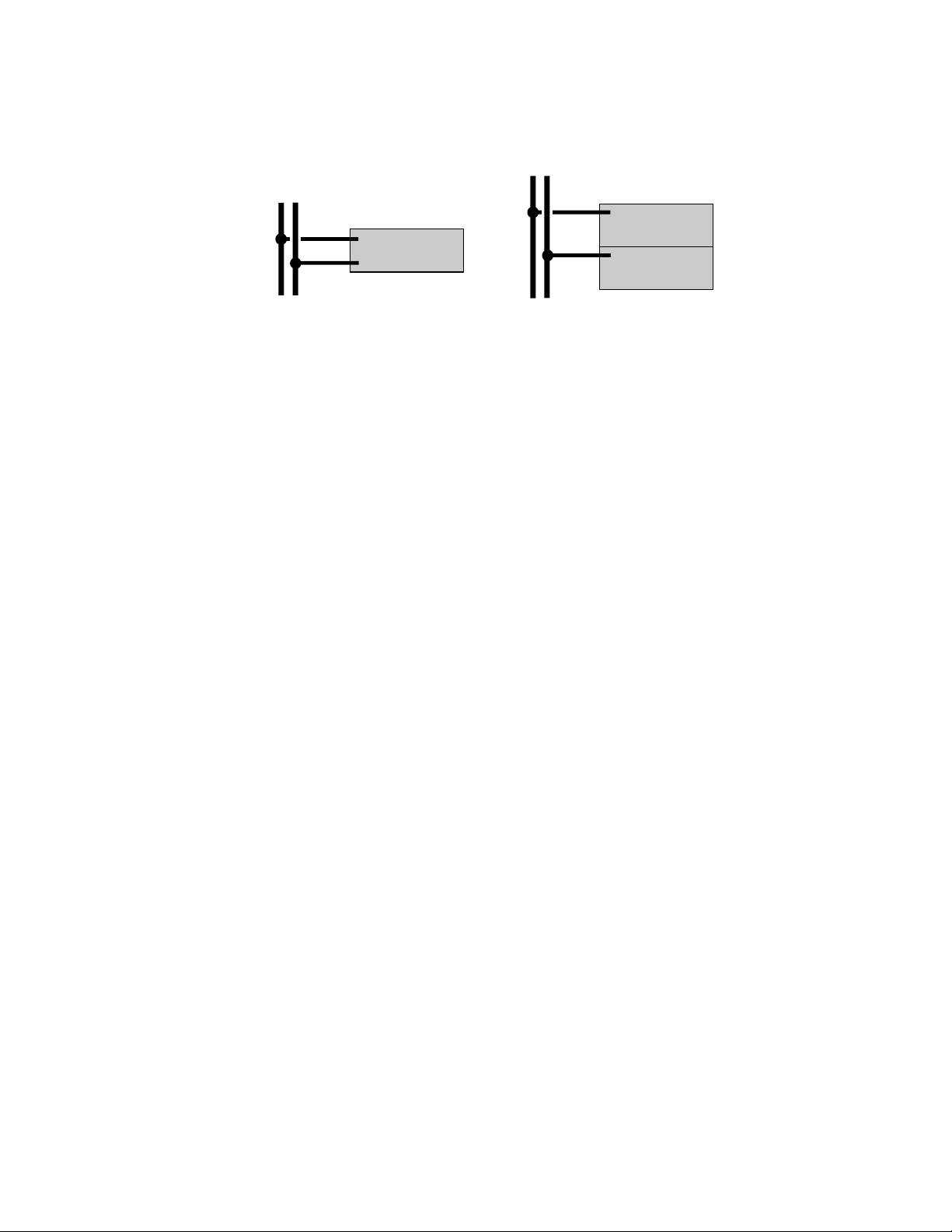
Redundancy for Ethernet controllers
Ethernet FSC controllers support communication redundancy.
Communication redundancy involves a separate physical connection
to communicate with the FSC controller.
The server supports the following redundancy options:
n Redundant connection to a single Central Part via a single,
redundant 10018/E/E COM module
n Redundant connection to redundant Central Parts via a single,
non-redundant 10018/E/1. COM module on each Central Part
Figure 1-6: Redundancy options
12
Page 13
CP
A
A B
B
CP1
CP2
A
A B
B
Chapter 1 - Planning considerations for Honeywell FSC controllers
Communication settings for Honeywell FSC
The communication settings are specific to the controller type (serial
or Ethernet).
Serial connection settings for Honeywell FSC
The RS-232 connection is made to the controller's COM module,
which can be of the following types:
n 10004/./.
n 10014/./.
Communication address
To communicate with a serial FSC controller, the server uses a
communicationaddress, which can be calculated using the
FSCSystem number specified when configuring the controller.
You use the FSC configuration utility, FSC Navigator, to specify the
FSCSystem number, which must be unique within a system of FSC
controllers.
The communicationaddress is equal to four times the FSCSystem
number.
Modbus data tables and function codes
Serial FSC controllers use the following Modbus data tables and
function codes.
In Quick Builder, you need to define a separate 'logical' controller for
each data table to which the server needs access. For example, if the
server needs access to the Discrete Output table and the and Input
Register table, you need to define two logical controllers.
13
Page 14

Chapter 1 - Planning considerations for Honeywell FSC controllers
Table 1-1: Modbus data tables
Data table Server addressable range
Discrete (digital) Output (coils) 00001–08192 (read/write)
Discrete (digital) Input (contacts) 10001–18192 (read only)
Input Register 30001–38192 (read only)
Holding Register 40001–48192 (read/write)
Serial FSC controllers support the following Modbus protocol
function codes:
Table 1-2: Modbus function codes
Function code Description
01 Read output status
02 Read input status
03 Read output registers
04 Read input registers
05 Force Single Coil
06 Preset Single Register
Ethernet connection settings for Honeywell FSC
The Ethernet connection is made to the controller's 10018/E/1 or
10018/E/E COM modules.
Communication address
To communicate with an Ethernet FSC controller, the server uses a
communicationaddress, which can be calculated using the
FSCSystem number specified when configuring the controller.
You use the FSC configuration utility, FSC Navigator, to specify the
FSCSystem number, which must be unique within a system of FSC
controllers.
14
The communicationaddress is equal to four times the FSCSystem
number.
Page 15

Chapter 1 - Planning considerations for Honeywell FSC controllers
Ethernet data tables
Ethernet FSC controllers use the following Modbus data tables.
In Quick Builder, you need to define a separate 'logical' controller for
each data table to which the server needs access. For example, if the
server needs access to the Coils table and the Registers table, you
need to define two logical controllers.
ATTENTION: The following points can only be built on an SOE
only controller:
l FSC variables with a SER sequence number, but without a DCS
address. This includes FSC variables with a SER sequence
number which are located in a FSC network. See the section
"FSC network configuration" in the topic titled "Ethernet
connections for Honeywell FSC" for more information.
l FSC system events. See the topic titled "Reserved SER
numbers" for more information.
Table 1-3: Ethernet data tables
Data Table Server Addressable Range (DCS address)
Coils (FSC types: I, O) 1–8192
SOE Only N/A
Registers (FSC types: BI, AI, BO, AO) 10001–18192
Assigning SER numbers for sequence of events
FSC controllers have SOE (Sequence of Events) capabilities. If you
want the server to record a controller's SOEs in its SOE log, you need
to assign an SER (Sequence of Events Recorder) number to each
internal address.
ATTENTION: In the case of a serial FSC controller, you need to
define a BaseSER for the controller.
15
Page 16

Chapter 1 - Planning considerations for Honeywell FSC controllers
To record a controller's SOEs in its SOE log
1. Assign an SER number to each internal address you want the
server to record. (It is recommended that you assign SER numbers
in a tight block for each controller.)
You use the FSC configuration utility, FSC Navigator, to assign SER
numbers.
2. When defining the controller in Quick Builder, select the SOE
Enable check box. (If you define several logical controllers, only
select this for one controller.) See the topic titled "Main properties
for a Honeywell FSC controller" for more information.
3. Assign a separate point, in Quick Builder, to each SER number. A
point can only have one SER number associated with it.
Reserved SER numbers
FSC controllers reserve the following SER numbers for system events.
If you want the server to log these system events, you need to assign
points to them that are reserved for system events.
SER Number (serial) SER Number (Ethernet) System Event
BaseSER 0 All forces cleared
BaseSER + 1 1 FSC System Fault
BaseSER + 2 2 SER Buffer Full
BaseSER + 3 3 SER Buffer Empty
BaseSER + 5 5 Force Event
ATTENTION:
l BaseSER + 4 (4 in the case of Ethernet) is not a valid event.
l The 'SER Buffer Empty' event cannot be stored in server SOE.
If a point is defined with this SER number, it is ignored.
l To be logged on to the SOE display when using an Ethernet
FSC controller, the System Events must be built on a SOE only
controller. This is because System Events have no DCS address
associated with them.
16
Page 17

Interpreting SOE lines
The following fields of the server's SOE file are populated for each
SOE with a matching SER number:
Field Description
Chapter 1 - Planning considerations for Honeywell FSC controllers
Date &
Time
Source The server's point ID that corresponds with this SOE.
Condition The SER number associated with this SOE.
Action Only applicable to Ethernet controllers. Information indicator
Description The server's point description.
Value The value returned in the SOE (if applicable).
The date and time given to the SOE by the controller.
dependent on the types of SER. See the section below titled "Action
descriptions."
For a status point built against a coil, this displays the appropriate state
descriptor for that point. Indeterminate values display either blank or
zero.
Action descriptions
Event Type FSC Data Type
FSC
Description
Server-action
Field
Event Report
Process Variable Event Boolean True to False F
1
System events. See the topic titled "Reserved SER numbers.“
2
Actions that are not applicable or indeterminate appear as --.
1
Any N/A
False to True T
Analog Low LO
Healthy HLT
High HI
2
17
Page 18

Chapter 1 - Planning considerations for Honeywell FSC controllers
Event Type FSC Data Type
Process Variable Force
Boolean Force Set SET
Event
Analog Force Set SET
Diagnostic Event Diagnostic
Event
FSC
Description
Server-action
Field
Force Cleared CLR
Force Cleared CLR
N/A
18
Page 19

CHAPTER
HONEYWELL FSC CHANNEL AND
2
CONTROLLER REFERENCE
This section describes the configuration and addressing information
specific to Honeywell FSC channels and controllers.
In this section:
Main properties for a Honeywell FSC channel 20
Port properties for a Honeywell FSC channel 22
Main properties for a Honeywell FSC controller 25
Optimizing Honeywell FSC scanning performance 29
19
Page 20

Chapter 2 - Honeywell FSC channel and controller reference
Main properties for a Honeywell FSC channel
The Main tab defines the basic properties for a Honeywell FSC
channel.
For information about how to create a channel, see "Building
controllers and channels" in the Quick Builder User’s Guide.
ATTENTION: If you use both serial and Ethernet Honeywell FSC
controllers, you need to create a separate channel for each type
of controller.
Property Description
Name The unique name of the channel. A maximum of 10 alphanumeric
characters (no spaces or double quotes). Note: In Station displays,
underscore characters ( _ ) appear as spaces.
Description (Optional) A description of the channel. A maximum of 132
alphanumeric characters, including spaces.
Associated
Asset
Marginal
Alarm Limit
The Tag Name of the Asset to be associated with the controller.
The communications alarm marginal limit at which the channel is
declared to be marginal. When this limit is reached, a high priority
alarm is generated. To change the priority of the alarm system wide,
see the topic titled "Configuring system alarm priorities" in the Server
and Client Configuration Guide. To change the priority of the alarm for
one channel, see the topic titled "About configuring custom system
alarm priorities for an individual channel or controller" in the Server
and Client Configuration Guide.
A channel barometer monitors the total number of requests and the
number of times the controller did not respond or response was
incorrect. The barometer increments by two or more, depending on
the error, and decrements for each good call.
To calculate an acceptable marginal alarm limit, use the formula:
Square root of the number of controllers on the channel × Marginal
Alarm Limit defined on those controllers (Normally, you specify the
same value for all controllers on a channel).
20
For example, if there are 9 controllers on the channel and their
Page 21

Property Description
Marginal Alarm Limit is set to 25, the value would be 3 (which is the
square root of 9) × 25 = 75.
Chapter 2 - Honeywell FSC channel and controller reference
Fail Alarm
Limit
Connect
Timeout
Read
Timeout
The communications alarm fail limit at which the channel is declared
to have failed. When this barometer limit is reached, an urgent alarm
is generated. To change the priority of the alarm system wide, see the
topic titled "Configuring system alarm priorities" in the Server and
Client Configuration Guide. To change the priority of the alarm for one
channel, see the topic titled "About configuring custom system alarm
priorities for an individual channel or controller" in the Server and
Client Configuration Guide.
Set this to double the value specified for the channel Marginal Alarm
Limit.
The time (in seconds) the server waits to connect to the Port and the
Redundant Port of the controller before abandoning the connection.
The default is 10 seconds for both the Port and the Redundant Port.
You can set different values for these two ports.
Use the default values unless the communications lines have a high
error rate or you are using modems.
The time (in seconds) that the server waits for a reply from the Port
and the Redundant Port of the controller. The default is 2 seconds for
both the Port and the Redundant Port. You can set different values for
these two ports.
Use the default values unless the communications lines have a high
error rate or you are using modems.
Item Type The type of channel specified when this item was created.
Last
The date and time the channel properties were modified.
Modified
Last
The date and time the channel was last downloaded to the server.
Downloaded
Item
Number
The unique item number currently assigned to this channel, in the
format CHNcccc, where cccc is the channel number.
You can change the Item Number if you need to match your current
server database configuration. The number must be between 0001 and
21
Page 22

Chapter 2 - Honeywell FSC channel and controller reference
Property Description
the maximum number of channels allowed for your system. For more
information about setting the maximum value, see the topic titled
"Adjusting sizing of non-licensed items" in the Supplementary
Installation Tasks Guide. Note that the maximum number of channels
that may be used in a system is defined in the Experion specification
for that Experion release, This number is likely to be less than the
maximum number that can be configured in the database as shown in
"Adjusting sizing of non-licensed items."
Port properties for a Honeywell FSC channel
The Port tab defines the communication-related properties for a
channel. The Port Type for FSC controllers can be:
n Serial. Only applicable to a directly-connected serial FSC
controller. A serial communications interface, such as RS-232. See
the section below titled "Serial port properties" for more
information.
n TerminalServer. Only applicable to a serial FSC controller that
communicates with the server via a terminal server. See the
section below titled "Terminal Server port properties" for more
information.
n LANVendor. Only applicable to an Ethernet FSC controller. See the
section below titled "LANVendor port properties" for more
information.
Serial port properties
ATTENTION: Only applicable to serial FSC controllers.
Property Description
Serial Port
Name
Baud rate The number of data bits per second.
The device name of the serial port.
The default is 9600.
22
Number of The number of data bits used for transmission.
Page 23

Chapter 2 - Honeywell FSC channel and controller reference
Property Description
Data Bits The default is 8.
Stop Bits The number of stop bits used for transmission
The default is 1.
Parity Defines parity verification of each character and must match
configuration on the end device.
The default is NONE.
Checksum The type of checksum error detection used for the port. Select the
value that matches the setting on the communication device:
l CRC16_0 or CRC16_1 (if Cyclic Redundancy Check (CRC) is set)
l ONESCOMP or TWOSCOMP (if Longitudinal Redundancy Check
(LRC) is set)
l XOR (If exclusive or is set)
XON/XOFF The type of XON/XOFF software flow control used to stop a receiver
from being overrun with messages from a sender. The types are:
l Input (use XON/XOFF to control the flow of data on the receive
line)
l None (default)
l Output (use XON/XOFF to control the flow of data on the
transmit line)
Handshaking
For RS-232
Options
l Enable RTS/CTS flow control. Stops a receiver from being overrun
with messages from a sender by using RTS/CTS flow control.
l Detect DCD. Select if the Data Carrier Detect communication
status line of the COM port requires monitoring (usually when
using modem or microwave linking). When selected, the
communications fails if the desired COM status line is not
high—for example, on a dial-up link connection for a modem.
l Detect DSR. Select if the Data Set Ready communication status
line of the COM port requires monitoring (usually when using
modem or microwave linking). When selected, the
23
Page 24

Chapter 2 - Honeywell FSC channel and controller reference
Property Description
communications fails if the desired COM status is not achieved.
Note: No options are available for RS-422.
For RS-485. The server does not support RS-485 for FSC controllers.
Terminal Server port properties
ATTENTION: Only applicable to serial FSC controllers.
Property Description
Terminal
Server TCP
The name and port number of terminal server to which the channel is
connected.
Host Name
You can specify either a TCP host name or an IP address, but it must
Terminal
Server TCP
match the TCP host name used when you installed and internally
configured the terminal server.
Port No
Idle Timeout The time, in seconds, the channel waits for a successful connection to
the server before closing the connection.
A value of 0 indicates that the connection is never closed.
Checksum The type of checksum error detection used for the port. Select the
value that matches the setting on the communication device:
l CRC16_0 or CRC16_1 (if Cyclic Redundancy Check (CRC) is set)
l ONESCOMP or TWOSCOMP (if Longitudinal Redundancy Check
(LRC) is set)
l XOR (If exclusive or is set)
24
LANVendor port properties
ATTENTION: Only applicable to serial FSC controllers.
Page 25

Chapter 2 - Honeywell FSC channel and controller reference
Property Description
Port Name Leave blank.
Redundant port properties
A communications link being used as a redundant link requires an
additional port definition for the redundant port. After you complete
the port definition, enter the same kind of port definition for the
redundant port.
Main properties for a Honeywell FSC controller
The Main tab defines the basic properties for a Honeywell FSC
controller.
For information about how to create a controller, see "Building
controllers and channels" in the Quick Builder User’s Guide.
Property Description
Name The unique name of the controller. A maximum of 10
alphanumeric characters (no spaces or double quotes). Note: In
Station displays, underscore characters ( _ ) appear as spaces.
Description (Optional) A description of the controller. A maximum of 132
alphanumeric characters, including spaces.
Associated
Asset
Channel Name The channel on which the controller communicates with the
Marginal Alarm
Limit
The Tag Name of the Asset to be associated with the alarm group.
server.
If you use both serial and Ethernet controllers, you must select a
serial/terminal server channel for a serial controller, and a
LANHoneywell channel for an Ethernet controller.
The communications alarm marginal limit at which the controller
is declared to be marginal. When this limit is reached, a high
priority alarm is generated. To change the priority of the alarm
system wide, see the topic titled "Configuring system alarm
priorities" in the Server and Client Configuration Guide. To change
the priority of the alarm for one controller, see the topic titled
25
Page 26

Chapter 2 - Honeywell FSC channel and controller reference
Property Description
"About configuring custom system alarm priorities for an
individual channel or controller" in the Server and Client
Configuration Guide.
A controller barometer monitors the total number of requests and
the number of times the controller did not respond or response
was incorrect. The barometer increments by two or more,
depending on the error, and decrements for each good call.
The default value is 25.
Fail Alarm Limit The communications alarm fail limit at which the controller is
declared to have failed. When this barometer limit is reached, an
urgent alarm is generated. To change the priority of the alarm
system wide, see the topic titled "Configuring system alarm
priorities" in the Server and Client Configuration Guide. To change
the priority of the alarm for one controller, see the topic titled
"About configuring custom system alarm priorities for an
individual channel or controller" in the Server and Client
Configuration Guide.
Dynamic
Scanning
Fastest Scan
Period
Communication
Address
Set this to double the value specified for the controller Marginal
Alarm Limit.
The default is 50.
Select the Dynamic Scanning check box to enable dynamic
scanning of all point parameters on this controller. The default
setting for this check box is selected.
Define the fastest possible scan period (in seconds) that dynamic
scanning will scan point parameters on this controller. The default
is 15 seconds.
The dynamic scanning period does not affect the static scanning
rate for a parameter. For example, if the scanning rate for a
parameter is 10 seconds, and the dynamic scanning rate for the
controller is 15 seconds, the parameter will still be scanned at a
period of 10 seconds.
Set this to four times the FSC System number. The FSCSystem
number is set using the FSC configuration utility, FSC Navigator.
See the section "Communication address" in the topic titled "Serial
connection settings for Honeywell FSC."
26
Page 27

Chapter 2 - Honeywell FSC channel and controller reference
Property Description
FSC Type Shows the controller type, which corresponds to the type of
channel (serial or Ethernet) selected in Channel Name.
Data Table The data table that this controller addresses.
l Serial controller, see the section "Modbus data tables and
function codes" in the topic titled "Serial connection settings
for Honeywell FSC"
l Ethernet controller, see the section "Ethernet data tables" in
the topic titled "Ethernet connection settings for Honeywell
FSC"
Diagnostic Applicable only to a serial controller. The value, in seconds,
between diagnostic polls. The default is 60 seconds.
To disable diagnostic polls, set the value to 0.
BaseSER Applicable only to a serial controller. The base address for this
controller. See the topic titled "Assigning SER numbers for
sequence of events" for more information.
IP Address 1
The controller's Ethernet addresses.
IP Address 2
SOE Enable
Select SOE Enable if you want SOE data. Specify the time, in
seconds, between polls for SOE data in SOERate.
SOE Rate
Only one logical controller per physical FSC controller can have
SOE Enabled. If an SOE only controller is built, this should be the
only logical controller with SOE enabled for that particular
physical FSC controller.
The SOE Rate must be a minimum of 5 seconds and defaults to 30
seconds.
See the topic titled "Assigning SER numbers for sequence of
events" for more information.
Sync Enable
Select Sync Enable if you want to synchronize the controller time
with the server time. Specify the time, in minutes, since midnight
Sync Time
before synchronizing in SyncTime.
The default is –1 (no synchronization).
27
Page 28

Chapter 2 - Honeywell FSC channel and controller reference
Property Description
See the topic titled "About time synchronization on Honeywell FSC
controllers" for more information.
Item Type The type of controller specified when this item was created.
Last Modified The date and time the controller properties were modified.
Last
Downloaded
Item Number The unique item number currently assigned to this controller, in
The date and time the controller was last downloaded to the
server.
the format RTUnnnnn.
You can change the Item Number if you need to match your
current server database configuration. The number must be
between 00001 and the maximum number of controllers allowed
for your system.
For more information about setting the maximum value, see the
topic titled "Adjusting sizing of non-licensed items" in the
Supplementary Installation Tasks Guide.
Note that the maximum number of controllers that may be used in
a system is defined in the Experion specification for that Experion
release, This number is likely to be less than the maximum number
that can be configured in the database as shown in "Adjusting
sizing of non-licensed items."
About time synchronization on Honeywell FSC controllers
28
You can synchronize the time of FSC controllers with the server.
The Sync Time parameter is specified in minutes since midnight.
When the assigned time is reached, the server sends a
synchronization command with the current time to the controller.
If you define several 'logical' controllers for a particular controller, you
can specify a different synchronization time for each logical
controller, in order to synchronize the physical controller at different
intervals in the day.
Page 29

Chapter 2 - Honeywell FSC channel and controller reference
Optimizing Honeywell FSC scanning performance
The maximum amount of data that can be acquired from an FSC
controller is influenced by the rate of sending scan packets to the
controller. An understanding of FSC scan packets will help you
configure points so that optimal data acquisition performance is
achieved, by maximizing the amount of data acquired with each scan
packet.
The scan packets that have been built can be listed by using the list
scan utility, lisscn. Listing scan packets helps verify the scanning
strategy. See the Server and Client Configuration Guide for usage of
lisscn.
29
Page 30

Chapter 2 - Honeywell FSC channel and controller reference
30
Page 31

CHAPTER
3
HONEYWELL FSC POINTS REFERENCE
This section describes how to configure points for a Honeywell FSC
controller using Quick Builder.
In this section:
Defining a Honeywell FSC address for a point parameter 32
31
Page 32

Chapter 3 - Honeywell FSC points reference
Defining a Honeywell FSC address for a point parameter
The format for an FSC data table address is:
ControllerName Address
Part Description
ControllerName The name of the FSC controller.
Address The address in the controller where the value is recorded.
The address syntax can be either:
l Address syntax for coils and registers
l Address syntax for SOE only points
See the relevant sections below for more information.
If you would like help with the address, you can use the Address
Builder. To display the Address Builder, click next to Address.
Address syntax for coils and registers
Address [Format|BitNumber] [SER SerNumber]
Part Description
Address
The server addressable memory address within the controller's data
table.
l Serial controller, see the section "Modbus data tables and function
codes" in the topic titled "Serial connection settings for Honeywell
FSC"
l Ethernet controller, see the section "Ethernet data tables" in the
topic titled "Ethernet connection settings for Honeywell FSC"
32
Format
(Optional) Select an appropriate format to read raw values.
To scale See the section below titled "Scaling with data formats."
Page 33

Part Description
To read without scaling Select a format of C16, or enter a 0, to read all 16
bits in the register without scaling. To read less than 16 bits without
scaling, enter the starting bit number (1 to 15). If you are not using
scaling, the point range is still used for PV indicator bar height only (the
PV indicator bar is on the Point Detail display on Station).
To read floating point values The supported floating point formats are
specific to the controller type:
l Serial, see the section below titled "IEEEFP formats for serial
controllers"
l Ethernet, see the section below titled "Data formats supported for
Ethernet controllers"
Select format IEEEFP to read two consecutive registers as a single
precision floating point number.
Chapter 3 - Honeywell FSC points reference
BitNumber
SerNumber
(Optional) For Input register and Holding register data tables, a starting
bit number can be specified. The valid range is 0 (default) to 15 where 0
is the right most bit in the 16-bit register.
Analog and accumulator point parameters can read up to 16 bits.
Status point parameters read 1, 2, or 3 consecutive bits.
The SER number. See the topic titled "Assigning SER numbers for
sequence of events" for more information.
ATTENTION: For a status point with an OP configured with four
output states (that is, across two consecutive coils), control of the
OP is carried out by executing separate writes to each of the two
coils. Therefore, a value is written to the first coil then another
immediately to the second coil. FSC controller logic should be
programmed to make allowance for these two separate writes
operations.
Note that enabling Reverse for a status point will not reverse the
value recorded for any SOEs generated for that point.
33
Page 34

Chapter 3 - Honeywell FSC points reference
Example
Analog point
PV source 161 U4095 SER 1000
SP destination 162 U4095
Mode destination 25 1
Status point
PV source 26
Accumulator point
PV source 171 C16
IEEEFP formats for serial controllers
Format Description
IEEEFPB Bytes are big endian format (this is the same as IEEEFP)
IEEEFPBB Bytes are byte-swapped big endian format
IEEEFPL Bytes are little endian format
IEEEFPLB Bytes are byte-swapped little endian format
ATTENTION:
l IEEEFP numbers use two data addresses to hold the number,
address and address -1. Do not specify address -1 (the lower
address) as the point parameter address.
l When configuring PLC data tables, do not assign overlapping
data addresses if floating point values are used and do not set
an IEEEFP address to 1.
34
Data formats supported for Ethernet controllers
FSC types: BI, BO
Page 35

Chapter 3 - Honeywell FSC points reference
Format Description
S8B Short signed integer
S16B Signed word
S32B Signed long integer
IEEEFP IEEE Floating point
FSC types: AI, AO
Format Description
FSC020MA 0 - 20 mA
FSC420MA 4 - 20 mA
FSC05V 0 - 5 V
FSC15V 1 - 5 V
FSC010V 0 - 10 V
FSC210V 2 - 10 V
Scaling with data formats
Parameter values with addresses in the Input register and Holding
register data tables can be scaled with a data format. Select the
format that corresponds to the counts that have been set in the PLC
register.
ATTENTION: If auxiliary parameters have a data format type that
requires scaling (U4095, U999, and so on), they will take the
same range as the PV.
The data format tells the server how to interpret the register value.
Raw values in the PLC register tables can be scaled by the 0% and
100% point range values in order to convert them into engineering
units (EU).
To select a format for scaling, you select the format that corresponds
to the counts that have been set in the register where the point
parameter value is sourced.
35
Page 36

Chapter 3 - Honeywell FSC points reference
Figure 3-1: Scaling raw data
Address syntax for SOE only points
POS: Index SER SerNumber
Part Description
Index
SerNumber
The server's internal position allocated to this point. It must be unique.
Range = 1–8192
The SER number. See the topic titled "Assigning SER numbers for
sequence of events."
36
Page 37

CHAPTER
TROUBLESHOOTING HONEYWELL FSC
4
ISSUES
This section describes troubleshooting tasks for Honeywell FSC that
you can perform either on the server or from any Station.
In this section:
Accessing diagnostics for an Ethernet controller 38
Testing Honeywell FSC communications with the server 38
Troubleshooting Honeywell FSC communication errors for a serial
controller 41
Troubleshooting Honeywell FSC communication errors for an
Ethernet controller 41
37
Page 38

Chapter 4 - Troubleshooting Honeywell FSC issues
Accessing diagnostics for an Ethernet controller
System information and extended diagnostic data are accessible from
Station for FSC Ethernet controllers.
System information
To access FSC System Information, double-click the PV of an FSC
Ethernet controller point. Alternatively, click Details in the Controller
Status, which shows the Ext Diagnostics tab, then click the System Info
tab for the required link.
The system information and extended diagnostic information is
updated automatically every 50 seconds. You can manually refresh
the information by clicking the Refresh button.
If the diagnostic data cannot be retrieved from the FSC Ethernet
controller, the most recent diagnostic data from the controller will
continue to be displayed until the new data is obtained. If successive
attempts to obtain diagnostic data from the controller fail, then an
alarm message will be generated in the Alarm Summary.
Extended diagnostics
To access FSC Extended Diagnostics, click the Details button in the
Controller Status. This shows up to 18 extended diagnostics messages
for each FSC Ethernet controller link. Each message represents a
hardware or software fault associated with that particular controller.
If an extended diagnostic message is present for a controller, an
alarm with a value of Message(s) Available will be present in the Alarm
Summary. To see the Extended Diagnostic information for an alarm
from the Alarm Summary, double-click the alarm to call up the
Controller Status, then click the Details button.
Testing Honeywell FSC communications with the server
Two diagnostic utilities, fsctst (for serial controllers) and fscetst (for
Ethernet controllers), are included as part of the server software.
These utilities test communications between the server and an FSC
controller. Channels and controllers must be downloaded from Quick
Builder before testing.
38
Page 39

Chapter 4 - Troubleshooting Honeywell FSC issues
n The server need not be running while using the utility as long as
the database service is running. If making a connection through a
terminal server, the server daemon service should also be running.
n The server is not communicating with your controllers. The test
utilities might interfere with communications.
To stop the server, enter the command at a Command Prompt:
hscserver /load
Answer 'y' to every prompt. This unloads the server, but leaves the
database in memory.
39
Page 40

Chapter 4 - Troubleshooting Honeywell FSC issues
To run the fsctst utility
1. Open a Command Prompt window.
2. Type fsctst and then press Enter.
3. Follow the directions as prompted.
You can read and write data to all registers that can be addressed
by the server.
For help using the utility, type ?.
4.
To check if your controllers are present, use the find a,b
command. This command locates all FSC controllers on the
channel with IDs between a and b.
For example:
C:\>fsctst
Enter LRN or device name of channel
chn0001
Enter command:
find 1,4
FIND device with id 1 to 4, at 28-May-98
14:06:52
Device 1 ?
Device 2 ?
Device 3 ? ...responding
Device 4 ?
Enter command:
q
To the left of the channel name is the channel number. The name
of the channel will be the letters 'chn' followed by the channel
number. For example, your Honeywell FSC channel 'COM3' might
be channel number 1. Its device name will be 'chn0001.'
40
Page 41

Chapter 4 - Troubleshooting Honeywell FSC issues
To run the fscetst utility
1. Open a Command Prompt window.
2. Type fscetst and then press Enter.
3. Follow the directions as prompted.
You can read and write data to all registers that can be addressed
by the server.
For help using the utility, type ?.
Troubleshooting Honeywell FSC communication errors for a serial controller
If any errors are encountered, review the previous sections.
Error Description
0106 (Device Timeout) No response was received from the controller.
8102 (MODBUS error 2 - illegal
data address)
After you have verified that the server is communicating with the
controller, you can build points to reference controller addresses.
ATTENTION: Remember to enable the channel from the SCADA
Controllers display.
You either specified an illegal address or an illegal
number of addresses.
Troubleshooting Honeywell FSC communication errors for an Ethernet controller
Ensure scan packets are optimized. See the topic titled "Optimizing
Honeywell FSC scanning performance" for more information.
If there are several logical controllers on a channel, make sure that
there is no more than one that has SOE enabled.
41
Page 42

Chapter 4 - Troubleshooting Honeywell FSC issues
42
Page 43

NOTICES
Notices
Trademarks
Experion®, PlantScape®, SafeBrowse®, TotalPlant®, and TDC 3000® are
registered trademarks of Honeywell International, Inc.
ControlEdge™ is a trademark of Honeywell International, Inc.
OneWireless™ is a trademark of Honeywell International, Inc.
Matrikon® and MatrikonOPC™ are trademarks of Matrikon
International. Matrikon International is a business unit of Honeywell
International, Inc.
Movilizer® is a registered trademark of Movilizer GmbH. Movilizer
GmbH is a business unit of Honeywell International, Inc.
Other trademarks
Microsoft and SQL Server are either registered trademarks or
trademarks of Microsoft Corporation in the United States and/or
other countries.
Trademarks that appear in this document are used only to the benefit
of the trademark owner, with no intention of trademark infringement.
Third-party licenses
This product may contain or be derived from materials, including
software, of third parties. The third party materials may be subject to
licenses, notices, restrictions and obligations imposed by the licensor.
The licenses, notices, restrictions and obligations, if any, may be found
in the materials accompanying the product, in the documents or files
accompanying such third party materials, in a file named third_party_
licenses on the media containing the product, or at
https://www.honeywell.com/en-us/privacy-statement..
Documentation feedback
You can find the most up-to-date documents on the Honeywell
Process Solutions Support website at:
http://www.honeywellprocess.com/support
43
Page 44

Notices
If you have comments about Honeywell Process Solutions
documentation, send your feedback to: hpsdocs@honeywell.com
Use this email address to provide feedback, or to report errors and
omissions in the documentation. For immediate help with a technical
problem, contact HPS Technical Support through your local
Customer Contact Center, or by raising a support request on the
Honeywell Process Solutions Support website.
How to report a security vulnerability
For the purpose of submission, a security vulnerability is defined as a
software defect or weakness that can be exploited to reduce the
operational or security capabilities of the software.
Honeywell investigates all reports of security vulnerabilities affecting
Honeywell products and services.
To report a potential security vulnerability against any Honeywell
product, please follow the instructions at:
https://www.honeywell.com/en-us/product-security.
Support
For support, contact your local Honeywell Process Solutions
Customer Contact Center (CCC). To find your local CCC visit the
website, https://www.honeywellprocess.com/en-US/contact-
us/customer-support-contacts/Pages/default.aspx.
Training classes
Honeywell holds technical training classes that are taught by process
control systems experts. For more information about these classes,
contact your Honeywell representative, or see
http://www.automationcollege.com.
44
 Loading...