


EXPERION PKS
RELEASE 516
UOC User Guide
EPDOC-X512-en-516A
August 2020

Disclaimer
This document contains Honeywell proprietary information. Information contained herein is to be
used solely for the purpose submitted, and no part of this document or its contents shall be
reproduced, published, or disclosed to a third party without the express permission of Honeywell
International Sàrl.
While this information is presented in good faith and believed to be accurate, Honeywell disclaims
the implied warranties of merchantability and fitness for a purpose and makes no express
warranties except as may be stated in its written agreement with and for its customer.
In no event is Honeywell liable to anyone for any direct, special, or consequential damages. The
information and specifications in this document are subject to change without notice.
Copyright 2020 - Honeywell International Sàrl
- 2 -

Contents 3
Chapter 1 - About this guide 12
1.1 Revision history 12
1.2 Related documents 12
1.3 Terms and definitions 15
Chapter 2 - Overview of UOC features 19
2.1 Native Experion Integration 19
2.2 ControlEdge 900 Form Factor 19
2.3 FTE Uplink Connectivity 20
2.4 Ethernet I/O Connectivity 20
2.5 ControlEdge 900 21
2.6 Field Device Manager 22
2.7 EtherNet/IP Connectivity to I/O, Devices, and Controllers 22
2.8 CEE Control Processing 22
2.9 Control Builder Strategy Configuration 22
2.10 I/O Points and I/O Reference Blocks 23
2.11 Simulation 23
2.12 Control Redundancy 23
2.13 Peer-To-Peer Communication 24
2.14 Alarms and Events 25
2.15 Time Synchronization 25
2.16 Security 25
2.17 Licensing 25
2.18 vUOC 26
Chapter 3 - Networking 29
3.1 Uplink FTE Network 29
3.2 Downlink I/O Network Topology 30
3.2.1 HSR Ring Topology with 900 I/O 31
3.2.2 Redundant Star (PRP) Topology with 900 I/O 34
3.2.3 DLR Ring Topology with EtherNet/IP and 900 I/O devices 35
3.2.4 Non-Redundant Star to 900 I/O and EIP Devices 38
3.2.5 EtherNet/IP in Experion 40
- 3 -

Chapter 4 - Installation 43
4.1 Hardware Considerations 43
4.2 Firmware Considerations 43
4.2.1 Converting PLC CPM to UOC CPM 44
4.2.2 Upgrading UOC CPM to New Firmware Version 48
4.2.3 Upgrading UOC EPM to new Firmware Version 48
4.2.4 Upgrading UOC UIOM to new Firmware Version 50
4.2.5 Firmware and Software Upgrade Considerations for vUOC 51
4.2.6 Additional Maintenance Activities in Firmware Manager 51
Chapter 5 - Configuration 52
5.1 Configuration Studio 52
5.2 Define and add assets in your enterprise model 52
5.3 Control Building 52
5.4 Specifying a Time Server 52
5.5 FTE Device Index 52
5.6 Creating UOC Platform block 53
5.6.1 Method 1: Using the File Menu 53
5.6.2 Method 2: Using the Project Assignment Panel 53
5.7 UOC Platform Block 54
5.8 Secondary UOC Platform Block 69
5.9 CEE Function Block 70
5.10 Configure UOC for Retention Startup 80
5.10.1 Introduction 80
5.10.2 Configure RETENTIONTRIG block 80
5.10.3 Loading Retention Trigger Block 97
5.11 Configure ControlNet for UOC 103
5.12 Configure ProfiNet for UOC 104
5.13 Configuring DLR for UOC 104
5.14 Convert a non-redundant UOC to a redundant controller 106
5.14.1 Prerequisites: 106
5.14.2 To convert a non-redundant UOC to a redundant controller 106
5.15 Convert a redundant UOC to a non-redundant controller 107
5.15.1 Prerequisites 107
5.15.2 To convert a redundant UOC to a non-redundant controller 107
- 4 -

5.16 Licensing Model 107
5.16.1 I/O Analog/Digital point(s) license 107
5.16.2 Composite Device Point(s) License 108
5.16.3 License Matrix 108
Chapter 6 - Load Configuration 110
6.1 About load operations 110
6.1.1 Loaded versus project database versions 110
6.1.2 Load initiation and load dialog box 110
6.1.3 Load action with Compare Parameters function 111
6.1.4 Load options for server history and server displays configuration 111
6.2 Initial load order guidelines 112
6.2.1 Component deletion considerations 112
6.3 Load components from Project 113
6.3.1 Loading UOC 113
6.3.2 Loading CEE 115
6.3.3 Loading I/OMs and CMs 117
6.4 Load With Contents command 117
6.5 Reloading components from project 117
6.6 Upload to the Monitoring database 118
Chapter 7 - ControlEdge 900 I/O Device Connectivity 119
7.1 CE900 IO in UOC 119
7.1.1 Model numbers 120
7.1.2 ControlEdge 900 IO Version Compatibility Matrix 120
7.2 UOC Configuration 121
7.3 Controller Rack 123
7.3.1 Rules 123
7.3.2 Creating Controller Rack 123
7.3.3 Method 1: Using the CE900_I/O library 123
7.3.4 Controller Rack Configuration 125
7.3.5 I/OM Status Summary 125
7.4 I/O Rack (EPM) 126
7.4.1 Rules 126
7.4.2 Creating I/O Rack 127
7.4.3 Hardware Information 127
7.4.4 Soft Failures and Alarms 127
7.5 I/O Module 128
- 5 -

7.5.1 Rules 128
7.5.2 I/O Module Creation 128
7.6 Channel 130
7.6.1 Rules and Behaviors 130
7.6.2 Channel Type Configuration 130
7.6.3 Channel Configuration and Status 133
7.6.4 Soft Failures and Alarms 135
7.7 I/O Module Configuration 139
7.7.1 Maintenance 139
7.7.2 Module Configuration/Monitoring Tabs 140
7.7.3 Common CE900 Module Configuration/Monitoring Tabs 141
7.7.4 CE900 UIO DI Channel NAMUR Configuration/Monitoring Tabs 145
7.7.5 CE900 UAI Module Configuration/Monitoring Tabs 146
7.7.6 CE900 DI32-24VDC Module Configuration/Monitoring Tabs 149
7.7.7 CE900 DO32-24VDC Module Configuration/Monitoring Tabs 151
7.7.8 CE900 DI16-VAC Module Configuration/Monitoring Tabs 153
7.7.9 CE900 DO08-VAC Module Configuration/Monitoring Tabs 155
7.7.10 CE900 DI16-DRYCT Module Configuration/Monitoring Tabs 156
7.7.11 CE900 DO08-RELAY Module Configuration/Monitoring Tabs 158
7.7.12 CE900 AO04 Module Configuration/Monitoring Tabs 160
7.7.13 CE900 AI16-100MS Module Configuration/Monitoring Tabs 162
7.7.14 CE900 AO08 Module Configuration/Monitoring Tabs 164
7.7.15 CE900 DI16-VACDC Module Configuration/Monitoring Tabs 166
7.7.16 UIO Namur Support 168
Chapter 8 - EtherNet/IP Device Connectivity 170
8.1 EtherNet/IP Device Configuration in UOC 170
8.1.1 Slot 0 Diagnostic Information 171
8.1.2 Slot 0 Configuration 172
8.1.3 Configuring the EtherNet/IP GenAdapter Block 173
8.1.4 Configuring the IP address of an EtherNet/IP device 179
8.1.5 Configuring I/O module blocks 179
8.1.6 Assigning EtherNet/IP devices to the CEE 181
8.1.7 Configuring I/O Ref blocks in CMs to access data from EtherNet/IP devices 181
8.2 Configuration Parameters for arrayed custom parameters 182
8.3 Configuration Parameters for scalar (non-arrayed) custom
parameters 186
8.4 Scaling support for Generic Device 187
- 6 -

8.4.1 Scaling Configuration Tab 187
8.4.2 Configuration 188
8.4.3 To view and modify the scaling parameters in EtherNet/IP generic device
instances 188
8.5 UOC and ControlLogix integration 189
Chapter 9 - UOC Node Redundancy Operation 191
9.1 Redundancy configuration restrictions 191
9.1.1 FTE Device Index 191
9.2 Partner controller compatibility 191
9.2.1 Redundancy compatibility result - RDNCMPT 192
9.3 UOC 1-slot I/O rack 194
9.4 Redundancy synchronization 194
9.4.1 Synchronization states - RDNSYNCSTATE 194
9.4.2 Enable Synchronization - ENBLSYNCCMD 195
9.4.3 Disable Synchronization - DSBLSYNCCMD 195
9.4.4 Auto-Synchronization State - RDNAUTOSYNC 195
9.4.5 Inhibit Sync Reason - RDNINHIBITSYNC 196
9.4.6 Initial Sync Progress - RDNSYNCPROG 198
9.4.7 Maximum Initial Synchronization Time - RDNISTIMEMAX 198
9.4.8 Last Synchronization Time - SYNCTIMEBEG 198
9.4.9 Last Lost of Sync Time - SYNCTIMEEND 198
9.4.10 Redundancy Traffic Rate 198
9.4.11 Conditions that result in loss of sync 199
9.4.12 Conditions that do not result in loss of sync 199
9.5 Switchover and secondary readiness 199
9.5.1 Become Primary command - BECMPRICMD 200
9.5.2 Initiate Switchover - SWITCHCMD 200
9.5.3 Max Switchover Time - RDNSOTIMEMAX 200
9.5.4 Conditions that result in switchover 200
9.5.5 Conditions that do not result in a switchover 201
9.5.6 Network switchover considerations 202
9.6 Redundancy history 202
Chapter 10 - Operation 203
10.1 UOC States And Transitions 203
10.2 UOC Front Panel Indications 206
10.2.1 Ethernet Port LEDs 206
10.2.2 Behaviors of Status and Redundancy Role LEDs 206
- 7 -

10.2.3 Status LED 207
10.2.4 Redundancy Role LED 211
10.3 UOC Startup 212
10.3.1 Actions During Boot 212
10.3.2 Restart After Power Loss 214
10.3.3 vUOC States and Startup Behaviors 214
10.4 Using Station displays 214
10.4.1 Identifying UOC 215
10.4.2 UOC Controller Point Detail Display (Redundant) 215
10.4.3 UOC Controller Point Detail displays (Non- Redundant) 219
10.4.4 vUOC Controller Point Detail displays 223
10.4.5 UOC-CPM (Local I/O) Racks 226
10.4.6 UOC-EPM Racks 227
10.4.7 UIO Racks 228
Chapter 11 - Troubleshooting 230
11.1 What to do when faults occur 230
11.2 Initial checks 230
11.3 Checking Control Builder error code reference 230
11.3.1 Checking faceplate LEDs 230
11.3.2 Using Firmware Manager to capture diagnostic data 231
11.3.3 Viewing release information log 231
11.3.4 Checking server point build log 231
11.3.5 Checking server point build error log 232
11.3.6 Checking error log 232
11.4 Fixing common problems 232
11.4.1 Loss of power 232
11.4.2 Power-On Self Test (POST) does not complete 232
11.4.3 Module does not complete startup 233
11.4.4 One or both FTE LEDs are OFF 234
11.4.5 FTE receive fault diagnostic 234
11.4.6 Controller does not synchronize with backup 236
11.4.7 Fatal ECC error 236
11.4.8 Isolated (lonely) Node 237
11.4.9 Duplicate Device Index detection 238
11.5 UOC Controller soft failures 239
11.6 Additional status and fault messages 245
11.6.1 Redundancy-related notifications 245
- 8 -

11.6.2 OPM-related notifications - RDNOPMSTATUS parameter 245
11.7 Online diagnostics 245
11.8 Fault classifications 246
11.8.1 Hard/Severe Failures 248
11.8.2 UOC Redundancy Communication Issues if CPM is not securely connected
to the rack 249
11.8.3 Soft Failures 249
11.8.4 Installation-Startup Failures 250
11.8.5 Hardware Watchdog Timer Expired 250
11.8.6 Communications Failure 250
11.9 Communications and system time faults during startup 250
11.9.1 Non-redundant UOC Controller 251
11.9.2 Redundant Primary UOC Controller 252
11.9.3 Secondary UOC Controller 254
11.10 Gathering information for reporting problems to
Honeywell 257
11.11 Guidelines for requesting support 257
Chapter 12 - Control Execution Environment 258
12.1 Functional Highlights 259
Chapter 13 - vUOC 260
13.1 Introduction 260
13.1.1 vUOC controllers with Private Path and Downlink I/O adapters 260
13.1.2 Flat Network Downlink I/O Topology 261
13.1.3 VLAN Tagged Network Downlink I/O Topology 262
13.1.4 Network Downlink I/O Topology 263
13.2 Guidelines for integration of virtual controllers 264
13.3 Creating Network Connections 265
13.3.1 Creating a Standard vSwitch 266
13.4 Defining Port Groups 272
13.4.1 Adding a Port Group to a Standard vSwitch 272
13.5 Physical network support for VLAN topologies 276
13.5.1 First level Switch configurations 276
13.5.2 Downstream Switch configurations 278
13.5.3 I/O Device Port configurations 280
13.5.4 Control Edge 900 IO and Switch Configurations 281
13.6 Download 282
- 9 -

13.7 vUOC Deployment 282
13.7.1 Reconfigure Network Assignments 289
13.8 vUOC Provisioning (first-time start up only) 290
13.9 vUOC Configuration and Usage 293
13.10 vUOC and Virtualization Host Maintenance 293
13.11 vUOC and Virtualization Host Availability 296
13.11.1 Turning on Fault Tolerance protection for vUOC 296
13.11.2 Disabling Fault Tolerance protection for vUOC 298
Chapter 14 - Performance and Capacity Considerations 300
14.1 Key Specifications 300
14.2 Managing Processing Load 302
14.2.1 Relevant Parameters 302
14.2.2 Overall Load Limits 303
14.2.3 Cycle Overruns 304
14.2.4 CPU Free 304
14.2.5 Redundancy Throughput 305
Chapter 15 - Security Guidelines for UOC 306
15.1 General 306
15.2 Organizational Security 306
15.3 Physical Security 306
15.4 Communication Hardening 307
15.5 Securing Connection to Uplink Network 307
15.6 Securing Connection to Downlink Network 307
15.7 Maintenance, Configuration and Operation 308
15.8 Third Party Configuration Files 308
15.9 Third Party Firmware Files 308
15.10 Private Redundancy Network Path 308
15.11 Patch Management 309
15.12 Backup/Recovery Capability 309
Chapter 16 - Configuring a Secure Connection for Experion Integration 310
16.1 Secure Communications 310
16.1.1 Secure Communication System Planning 312
16.1.2 Configure and Setup Steps 312
16.1.3 Advanced Technical Information 313
- 10 -

16.1.4 Certificate Management 313
16.1.5 Secure Communications using IPSec 313
16.1.6 Secure Commuincations Using TLS 314
16.1.7 Secure Boot 314
16.2 Obtaining and Installing the software 314
16.3 Overview of an IPSec deployment 315
16.4 Set Enrollment Information 316
16.5 Creating the Certificate Authority 316
16.6 Creating a certificate for Engineering Station and Console 320
16.6.1 Creating a certificate 321
16.6.2 Importing certificate and private key on target machine 322
16.7 Configure ControlEdge UOC for use with IPSec 329
16.7.1 Installing Certificate Manager Configuration Console 329
16.7.2 Setup certificates and IPSec policy in UOC 338
16.8 Configuring IPSec to secure traffic to the UOC 347
16.8.1 Configure and Activate Security Policies 347
16.8.2 Enable IPSec policy on PCs 347
16.8.3 Disable IPSec policy on Engineering Station/Console 351
16.8.4 Enable IPSec policy rules in the UOC 351
16.8.5 Disable IPSec policy rules in the UOC 353
16.9 Backup and Restore of CA 355
16.9.1 Backup 355
16.9.2 Restore 361
16.10 Renewal and revocation of certificates 365
16.10.1 CA Root certificate 365
16.10.2 Renewing the CA Root certificate 366
16.10.3 PC certificates 367
16.10.4 Revocation 367
16.10.5 UOC certificates 370
16.10.6 Revocation 370
16.11 Troubleshooting 370
16.11.1 How to reset UOC for IPSec configuration? 370
16.11.2 How to reset IPSec configuration on Windows? 371
16.11.3 Diagnosing IPSec with Network Analysis Software 371
16.11.4 If CMCC upload a large number of policies, the read data from the
transport connection can not be received 371
- 11 -

CHAPTER
1
ABOUT THIS GUIDE
1.1 Revision history
Revision Date Description
A August 2020 Initial release of the document.
1.2 Related documents
The following list identifies publications that may contain information relevant to the information
in this document. You can find these documents on https://www.honeywellprocess.com/en-
US/support/pages/all-documentation.aspx.
- 12 -

Document Description
Firmware
Manager User
Guide_EPDOCX470.pdf
This document describes the tool used for loading
firmware to hardware modules of the UOC system and for
uploading diagnostics information from them.
Hardware
Planning and
Installation
Guide_HWDOCX430-en-H.pdf
This document describes hardware components and
related installation practices for the ControlEdge 900
family of controller hardware.
Virtualization
Planning and
Implementation
Guide_EPDOCX147-en-A.pdf
This guide provides high-level guidance on how to
implement a virtualized Experion environment.
EtherNet_IP_
Users_Guide_
EPDOC-X399en-511A.pdf
This document provides an overview of the use of
EtherNet/IP™ communications with level 1 Experion
control systems and offers practical guidance to perform a
successful integration of EtherNet/IP with Experion.
Fault_Tolerant_
Ethernet_
Overview_and_
Implementation_
Guide_EPDOCXX37-en-511.pdf
This guide contains basic installation instructions and
configuration requirements for an FTE network and its
components. Detailed network planning and requirements
information is not included as this type of information is
site-specific.
Fault_Tolerant_
Ethernet_
Installation_and_
Service_Guide_
EPDOC-XX36en-511A.pdf
This document provides instructions for installing and
servicing the Fault Tolerant Ethernet Mux driver.
Network_and_
Security_
Planning_Guide_
EPDOC-XX75en-511B.pdf
This document contains networking and security-related
information applicable to Experion. It provides information
about the recommendations to assist you in planning,
setting up, and maintaining a secure environment for your
system.
Switch_
Configuration_
Tool_Users_
Guide_EPDOCX246-en-
This guide describes the user interface of the Switch
Configuration Tool and provides an overview for
configuring switches using the tool. It describes the tasks
to create new switch configuration, open an existing switch
configuration, generate text files from the switch
Chapter 1 - About this guide
- 13 -

Document Description
511A.pdf configuration, and load the new switch configurations to
the switches. It also briefly describes creating and saving
projects using the tool.
Control Builder
Components
Theory_EPDOCXX16-en511A.pdf
This guide provides detailed information on the
functionality of Control Builder and the function block
libraries it is used to configure. It does not cover
ControlEdge hardware modules such as the Control
Processor Module (CPM) or Input / Output Modules
(I/OMs).
Control Building
User’s Guide_
EPDOC_XX19_
en-511A.pdf
The procedures in this guide are intended to give you the
ability to perform basic tasks within the Control Builder
application such as configuring hardware devices,
continuous control strategies, and sequential control
strategies. Only representative forms are shown to
illustrate a procedure/concept.
Control Builder
Parameter
Reference
Guides_EPDOCXX18-en511A.pdf
This guide provides information about parameters
associated with configuration forms of function blocks in
Control Builder.
Control_Builder_
Components_
Reference_
EPDOC-XX15en-511.pdf
This document provides a brief technical reference of
function blocks configured through Control Builder.
Engineering Data
Builder (EDB)
User’s GuideEPDOC-X417en-511A.pdf
The Engineering Data Builder (EDB) add-in is a
productivity enhancement tool integrated with the Control
Builder.
EDB add-in deploys customized, reusable, and extensible
spreadsheets, allowing project engineers to save time in
updating configuration.
Virtualization
with the
Premium
Platform
EPDOC-X455en-B.pdf
This guide gets you started with the Honeywell Premium
Platform for Experion Virtualization Solutions.
Chapter 1 - About this guide
- 14 -

Term Definition
AI Analog Input
AO Analog Output
CA Certificate Authority
CBR Class Based Recipe
CDA Control Data Access
It is the Experion system communication infrastructure and data
access interface schema that provides application integration
with Experion system objects.
CEE Control Execution Environment
CIP Common Industrial Protocol
An industrial communication protocol now maintained as a
standard by the Open Device Venders Association (ODVA).
Cleartext Data that is stored or transmitted unencrypted
CM Control Module
CMCC Certificate Manager Configuration Console
Consolidate
Connections
A single connection used to group multiple I/O modules, instead
of one connection per I/O module.
Also referred to as Assembly connections, Rack connections,
Gateway connections.
ControlEdge
900
A family of controller hardware which can be assembled to create PLC or UOC
systems.
CPM Control Processor Module (also commonly referred to as
controller)
DI Digital Input
DLR DLR is a link layer protocol for establishing a form of ring
redundancy on an Ethernet network.
DO Digital Output
Downlink Shorthand term use to refer to one of two possible types of I/O
and device network that a UOC controller connects to.
EDB Engineering Data Builder
EDS Electronic Data Sheets
Chapter 1 - About this guide
1.3 Terms and definitions
- 15 -

Term Definition
Files which define the communication properties of devices
capable of connecting to EtherNet/IP networks.
EtherNet/IP EtherNet/IP™
EPM Expansion Processor Module
Ethernet communications module connecting distributed racks
of ControlEdge 900 I/O modules to the CPM.
ETAP EtherNet/IP™ Tap
A type of switch that allows a device incapable of supporting the
DLR redundancy protocol to form a non-redundant connection
into a DLR ring.
Expansion
I/O rack
I/O rack with EPM installed
FDM Field Device Manager
FTE Fault Tolerant Ethernet
GTAC Global Technical Assistance Center
HART Highway Addressable Remote Transducer
HMI Human Machine Interface
HPS Honeywell Process Solutions
HSR HSR (High Availability Seamless Redundancy) is a link layer
protocol for establishing a form of ring redundancy on an
Ethernet network. HSR is referred to as “Ring-HSR” in the UOC
platform block configuration form.
HW Hardware
IIS Internet Information Services
IKE Internet Key Exchange
I/O Input/Output
IP Internet Protocol
IPSec Internet Protocol Security
LEAP Lean Engineering of Automation Projects
Local I/O
rack
I/O rack with Control Processor Module installed (nonredundant)
NIC Network Interface Controller
NTP Network Time Protocol
Chapter 1 - About this guide
- 16 -

Term Definition
NVS Non-Volatile Storage
ODVA Open Device Venders Association
OTP One Time Password
OWD Open Wire Detected
PC Personal computer
PCCC Programmable Controller Communications and Commands
PCDI Peer Control Data Interface
PLC Programmable Logic Controller
Peer Server
Responder
Data sourcing service provided by the Experion Process Server
node which allows controllers like the UOC to access any data
presented by the Server’s data points via peer communication
over the supervisory network.
PRP Parallel Redundancy Protocol is a link layer protocol for
establishing a form of dual-path redundancy on an Ethernet
network.PRP is also referred to as “Star-PRP”.
PSM Power Status Module
PSU Power Supply Unit
PTP Precision Time Protocol PTP
IEEE-1588
It is a standardized internet networking protocol used for
synchronizing computer clock times in a distributed network of
computers. PTP provides higher precision than NTP. The UOC
supports time synchronization by either NTP or PTP on its uplink,
FTE network.
P&ID
Diagram
A diagram representing the Process and Instrumentation Design
of a plant or plant unit.
PWA Printed Wiring Assembly
RCM Recipe Control Module
Redundancy
Box
A network switch that allows another device to connect into a
ring topology even if the device itself cannot natively handle the
ring redundancy protocol.
Redundant
Controller
Rack
ControlEdge 900 rack capable of hosting a redundant pair of
CPMs.
Redundancy Module used with a CPM within a 1 I/O Slot Rack to implement
Chapter 1 - About this guide
- 17 -

Chapter 1 - About this guide
Term Definition
Module
(RM)
Dual Rack Redundancy.
SCM Sequence Control Module
SD Card Secure Digital Card
SW Software
TCP Transport Control Protocol
TLS Transport Layer Security
UI/O Universal Input/Output Module
UCM Unit Control Module
It is a container that represents a piece of or logical grouping of
physical equipment. A Recipe may be configured to acquire a
UCM before its procedure can be executed. A UCM can also be
used as an auxiliary resource.
UOC Unit Operations Controller
This is a term used to refer to the CPM when used as a controller
in the Experion PKS Distributed Control System.
Uplink Shorthand term used to refer to the supervisory Ethernet
network that the UOC controller connects to within an Experion
system.
UPS Uninterruptable Power Supply
Users Human Actors
User Goals What users are hoping to achieve at a high level and why. Independent of
system implementation. Should be able to be linked to stakeholder business
goals and SRS use cases.
User Scenarios Specific examples that elaborate on user goals in a context. Told in the form of
stories. Independent of system implementation.
vUOC Virtual Unit Operations Controller
- 18 -

CHAPTER
2
The Unit Operations Controller (UOC) is a high value, low cost, rack-based process controller that
can be applied to any process control application in any industry. Its form factor, cost profile and
licensing model make it especially well-suited to industries that prefer to limit the scope of a single
controller to a single process unit, and to industries that require powerful batch enablers.
The UOC is paired with a virtualized controller called the virtual Unit Operations Controller
(vUOC).The vUOC provides a set of functions parallel to those of the UOC except that they are
deployed within a server hosted virtual machine.
Summary descriptions of UOC and vUOC features are presented within this section. Additional
details may be found elsewhere within this document and within the overall Experion document
set.
OVERVIEW OF UOC FEATURES
2.1 Native Experion Integration
UOC integrates natively into the Experion DCS in a fashion parallel to that of existing controllers
such as the C300 and C200E. It uses the same CEE (Control Execution Environment) control
solver as those controllers. Experion Fault Tolerant Ethernet provides redundant, level 2
communications to the UOC. Engineering Station, Direct Station and Flex Station nodes all
provide view of UOC parameter and alarm data via Experion native Control Data Access (CDA)
protocol. Communication, monitoring, displays, trending, historizing, advanced applications, batch
applications, configuration and field device management all work with the UOC controller in a
fashion equivalent to that of existing CEE controllers.
2.2 ControlEdge 900 Form Factor
UOC control algorithms and I/O communications processing run in a family of rack-resident
modules called ControlEdge 900. ControlEdge can be used to deploy high density control and I/O
installations meeting all environment and agency certification requirements with no restriction as
to cabinet type.
In addition to the UOC, components of the ControlEdge HW family can be used to deploy the
ControlEdge PLC, without the need to deal with a completely different component family.
The main components of UOC HW are listed here.
- 19 -

Component Description
CPM Control Processor Module
Referred to as UOC-CPM.
Host processor of control and communications supporting
redundant and non-redundant configurations. Provides two
uplink Ethernet ports for connectivity to FTE. Provides two
downlink Ethernet ports for connectivity to an I/O and device
network.
EPM Expansion Processor Module
Ethernet communications module connecting distributed racks
of ControlEdge 900 I/O modules to the CPM.
UI/OM Universal Input / Output Module
16 channel I/O module with universal channels which can be
configured as AO, DI or DO. Channels configured as AO support
HART protocol.
I/O Racks Five possible non-redundant racks which hold an EPM or a non-
redundant CPM together with 1, 4, 8 or 12 I/O Modules. Three of
the racks accommodate non-redundant power supplies. The 8
and 12 slot racks are available with redundant power supplies
and a power status module.
Redundant
CPM Rack
Redundant controller racking supporting two power supplies and
two CPM slots.
Power
System
AC or DC power supply modules and power status module.
Chapter 2 - Overview of UOC features
2.3 FTE Uplink Connectivity
Detailed information on the installation, planning and general characteristics of ControlEdge 900
HW components can be found in ControlEdge 900 Platform Hardware Planning and Installation
Guide_HWDOC-X430.pdf.
UOC connects to a redundant FTE supervisory network via its uplink Ethernet ports (port #1& port
#2). UOC hosts a full featured firewall allowing it to securely connect directly to level 2, FTEqualified, third party switches. UOC deployments do not require connectivity to FTE through a
separate firewall.
Beginning with Experion R510.2, the vUOC connects to a redundant FTE supervisory network via
its uplink Ethernet ports (virtual switches). A software-based firewall is included allowing a secured
connection directly to Level 2, FTE- qualified, third party switches.
2.4 Ethernet I/O Connectivity
UOC connects to an I/O and device network via its two downlink Ethernet ports (port #3 & 4).
- 20 -

Multiple application-dependent typologies are supported with two configurable options:
Module Type Model Number
UI/O module 900U01-0100
UAI module 900A01-0102
DI 24VDC module 900G32-0001
DO 24VDC module 900H32-0102
DI High Voltage AC 900G03-0102
DO High Voltage AC 900H03-0102
AI16-100MS (High Level Analog Input, 16 Channels) 900A16-0103
AO04-500MS (Analog Output, 4 Channels) 900B01-0101
AO08-500MS (Analog Output, 8 Channels) 900B08-0202
DI16-DRYCT (DI - 16ch Dry Contact Type) 900G01-0102
DI16-VACDC (DI - 120/240 VAC, 125 VDC (16ch-Iso)) 900G04-0001
DO08-RELAY (Digital Output Relays, 8 Channels) 900H01-0102
l When only ControlEdge 900 I/O racks are connected, a native ring redundancy based on the
High Availability Seamless Redundancy (HSR) protocol may be used, a star redundancy based
the Parallel Redundancy Protocol (PRP) may be used or a non-redundant star may be used.
l When ControlEdge 900 I/O racks are used together with 3rd party EtherNet/IP devices, a ring
redundancy based on Device Level Ring (DLR) may be used or a non-redundant star may be
used.
2.5 ControlEdge 900
ControlEdge PLC supports various input/output modules. The following I/O modules are included:
Chapter 2 - Overview of UOC features
Additional I/O modules will be made available in future releases of the Experion PKS.
NOTE : For Module AI16-100MS, the Model Number should be 900A16-0103 and the
firmware version should be 1.39 for the 100 ms scan rate support.
For below IO modules, there can be Model number mismatch between the IO module hardware
and the IO module reports.
- 21 -

Module Description
Model
Number
Module Number report by the IO
Module
Analog Output, 0 to 20mA, (4
channel)
900B010301
900B01-0101
Digital Input, Contact type, (16
channel)
900G010202
900G01-0102
Digital Output, Relays (8
channel)
900H010202
900H01-0102
Chapter 2 - Overview of UOC features
2.6 Field Device Manager
UOC supports integration with Experion Field Device Manager (FDM) for management of smart
field instruments. The FDM can view and manipulate the digital HART variables of field
instruments through the analog channels of UOC’s UI/OM.
The ability of UOC itself to access digital HART variables via a Field Device Server hosted on the
Engineering Station will be introduced in a future release.
2.7 EtherNet/IP Connectivity to I/O, Devices, and Controllers
UOC supports control through third party I/O and devices connected by the EtherNet/IP protocol
on its Ethernet downlink.
A set of EtherNet/IP devices come preinstalled and ready for instantiation within Experion Control
Builder. This includes Rockwell Allen Bradley’s ArmorPoint I/O, ArmorBlock I/O, PowerFlex Drive
and E3 Relay.
Support for other EtherNet/IP I/O and EtherNet/IP device types can be integrated by projects
personnel without dependence on a new Experion release through the use of Experion Control
Builder’s Parameter Definition Editor (PDE).
Also supported are User Defined Type (UDT) blocks which enable UOC to communicate over its
downlink via EtherNet/IP with Rockwell Allen Bradley’s ControlLogix.
2.8 CEE Control Processing
UOC hosts the well-proven Control Execution Engine (CEE) strategy solver used in existing
Experion controllers. CMs (Control Modules) are fully supported for continuous control strategies.
SCMs (Sequential Control Modules), UCMs (Unit Control Modules), RCMs (Recipe Control Modules)
and CBRs (Class Based Recipes) are fully supported for batch control strategies.
2.9 Control Builder Strategy Configuration
Like all CEE controllers, UOC’s control strategies are configured using Experion Control Builder.
Control Builder offers a rich set of tools for the creation of strategies to control continuous,
discrete and batch processes. Strategies may be created as individual instances or as replicable
templates. Bulk creation of UOC control strategies is supported through Experion’s Engineering
Data Builder (EDB) add-on to Control Builder. EDB allows application engineers to create large
configurations using an efficient, spreadsheet-driven workflow.
- 22 -

2.10 I/O Points and I/O Reference Blocks
UOC supports binding of I/O to control through a mechanism that allows the configuration of one
to be independent of the other. UOC I/O points may be introduced into the system independent of
UOC control strategies. UOC control strategies may be configured and tested independent of their
corresponding I/O.
This independence is achieved through two kinds of function blocks supported by Control Builder
and by CEE.
l I/O Points
o
I/O Points are Experion tagged blocks representing the device connected to the UOC
through an input or output channel of an I/O module.
o
They are typically tagged with the same name (up to 40 characters) that labels the
device in a P&ID diagram.
o
They serve as a connection target that binds a control strategy to an I/O channel.
o
They allow the binding to be made by name, without constraining the strategy to work
with the particular channel of a particular I/O Module.
o
They allow the configuration of the I/O Module to be separated from the configuration
of the control strategy.
o
They can be created before or after the corresponding control strategy.
o
In addition to I/O channels, they can be used to represent key parameter data which
do not correspond to actual I/O channels.
Chapter 2 - Overview of UOC features
l I/O Reference Blocks
o
I/O Reference Blocks are basic blocks instantiated in Control Modules to make an I/O
signal available for connection to algorithm blocks.
o
They are bound to I/O Points though named references independent of particular
channels in particular I/O Modules.
o
They support a simulation mode that allows for strategy checkout to be done in the
absence of I/O Modules.
o
They complement I/O Points by serving as the reference end of the connection to the
I/O Point.
o
In addition to referencing I/O channels, they can be used to reference key parameter
data which do not correspond to actual I/O channels.
UOC’s I/O Points and I/O Reference Blocks provide key enablers of the Lean Execution of
Automation Projects (LEAP) methodology supported by Experion.
2.11 Simulation
UOC may be used for both control and strategy-check-out simulation without the need to deploy a
special purpose simulation application. Simulation behaviors of strategies are controlled through
the SIMMODE parameter of I/O Reference blocks within the Control Module under test.
2.12 Control Redundancy
UOC optionally supports redundant control operation. Single Rack Redundancy is provided
through a single rack scheme where the partner CPMs are placed in the same rack along with
power supplies. The power supplies in a single rack scheme do not provide REDUNDANT power:
The left power supply provides power to the CPM mounted in the left slot. Likewise, the right power
- 23 -

Responding Node
Initiating Node
UOC vUOC
C300
C200E C200
UOC
ü ü ü ü ü
vUOC
ü ü ü ü ü
C300
ü ü ü ü ü
ACE
ü ü ü ü ü
C200E
ü ü ü ü ü
C200 Note
1
Note
1
ü ü ü
Chapter 2 - Overview of UOC features
supply provides power to the CPM mounted in the right slot.
Switchover from the active primary to the backup controller may be commanded manually. If a
fault occurs, the failed primary is detected automatically by virtue of comprehensive diagnostics,
leading toautomatic switchover. Switchover occurs within 500 milliseconds in order to ensure a
seamless transition, preserving all configuration data and live data, and with no disturbance to
outputs.
Dual Rack Redundancy is provided through 2 separate 1 I/O slot racks each with a power supply
and a Redundancy Module . Refer to the ControlEdge 900 Platform Hardware Planning and
Installation Guide_HWDOC-X430.pdf for additional information.
2.13 Peer-To-Peer Communication
UOC supports multiple forms of peer-to-peer communication across its uplink FTE connection.
l Control Data Access (CDA)
UOC uses Experion native CDA protocol for communication with peer partners as well as level 2
server and station nodes. Parameter reads are supported under a cyclic publication paradigm.
Parameter writes are supported under an acyclic store paradigm.
Within CMs and SCMs, the configuration of peer references is transparent to the application
engineer. They are specified by configuring fully qualified parameter names such as
“TT101.DATAACQ.PV” in expressions, inputs pins or selected output pins, without concern as to
whether the parameter is in the same UOC or in a different controller.
UOC’s CDA peer connections may also be used to reference data from SCADA points by virtue of
Experion Peer Server Responder capability.
The Experion node types with which UOC supports CDA peer-to-peer communication are listed in
the following table. This set will be expanded in future releases.
NOTE1: The C200 controller can respond to CDA peer communications from a UOC or vUOC
but cannot initiate them.
l Exchange Blocks
- 24 -

UOC supports a library of blocks which enable communication with third party PLCs and devices
via protocols which were originated by Rockwell Allen Bradley and now support transport over
Ethernet. Blocks within the EXCHANGE library allow initiation of and response to read and write
requests for flags, numeric and string arrays. EXCHANGE blocks support two protocols: the
Common Industrial ProtocolTM(CIP) and Programmable Controller Communication Commands
(PCCC).
l PCDI Blocks
UOC supports a library of blocks called Peer Control Data Interface (PCDI) which enable
communication with third party PLCs and devices via the Modbus TCP/IP protocol. Blocks within
the PCDI library allow initiation of read and write requests through a device proxy block to flag,
numeric and string arrays in a Modbus-capable peer controller.
2.14 Alarms and Events
UOC supports a comprehensive set of alarm and event reporting capabilities that integrate
seamlessly with Experion enablers for the display and historization of alarms and events.
Supported notification types include high, low and rate of change process alarms, state change
process alarms, state change system events, diagnostic events and batch events.
Chapter 2 - Overview of UOC features
2.15 Time Synchronization
UOC maintains an internal clock which is synchronized with external wall clock time.
Synchronization can be maintained over the uplink network using either the Network Time
Protocol (NTP) or the Precision Time Protocol (PTP). All alarms and events reported by UOC are
issued with synchronized time stamps.
2.16 Security
UOC has built in enablers to provide for the secure and robust operation of its control and I/O
configurations. This includes an uplink firewall that limits message types to those appropriate to
the mission of the FTE network. It includes a downlink firewall that limits message types to those
appropriate to the missions of 900 I/O and EtherNet/IP communication. UOC also supports
mechanisms of signed firmware and secure boot which insure only Honeywell authorized
firmware to be executed within the device.
2.17 Licensing
UOC systems are delivered under a licensing model which allows HW and SW components to be
deployed in the manner that most naturally fits the process control problem to be solved. Indirect
cost penalties for good design practices are avoided. The bulk of the cost associated with deploying
a UOC system is proportional to the count of Analog and Digital I/O points put into service. There is
little additional cost if a good design dictates the deployment of small, per unit controllers. Similarly,
there is little additional cost if the design dictates the deployment of small, modularized control
strategies.
For more information on Licensing refer to Licensing Model section.
- 25 -

Chapter 2 - Overview of UOC features
2.18 vUOC
As noted above, the virtual UOC provides a set of functions nearly equivalent to those provided by
the ControlEdge 900 based UOC. It is well suited to supervisory batch applications, lab applications
and control strategy checkout before strategies are deployed to a ControlEdge UOC
Differences between the two are driven by the nature of their hosting platforms and, to a certain
extent, by particular strengths that their respective deployments provide. Key differences are
highlighted by the following table.
- 26 -

Attribute UOC vUOC Comment
Host
Platform
l Runs on the
purposebuilt,
industry
hardened,
ControlEdge
CPM
l Runs as a
virtual
machine on
general
purpose PC
servers
Base Period l 50 ms l 50 ms or
500 ms
A second vUOC variant
supports a slower base
cycle in addition to the
50 ms base cycle
parallel to the UOC.
The slower variant
allows the vUOC to be
applied as a very large
batch supervisor
managing UOCs or
C200Es serving as
equipment controllers.
User
Memory
Capacity
l 32 MB l 32 MB in
the 50 ms
variant
l 128 MB in
the 500 ms
variant
The 500 ms variant of
the vUOC supports a
user memory database
4 X that of the UOC as
an additional enabler
of large supervisory
batch configurations.
Control
Redundancy
l Transparent
redundancy
support
based on
proprietary
enablers
l Not
currently
supported
The vUOC has no
native redundancy
enablers, but as an
alternative, it can
optionally be deployed
in virtual platforms
that provide high
availability solutions.
Support In
VEP
l Runs on
purposebuilt HW and
cannot run
within HPS’
Virtual
Engineering
Platform
l Can run
within HPS’
Virtual
Engineering
Platform
One of the key
deployments of the
vUOC is as a simulator
within VEP to support
early application
development.
Chapter 2 - Overview of UOC features
- 27 -

Attribute UOC vUOC C300
SIMC300
ACE
SIMACE
Hosting on Server No Yes No Yes Yes Yes
Direct I/O Connectivity Yes Yes Yes No No No
Deployment as Controller Yes Yes Yes No Yes No
Deployment as Simulator Yes Yes No Yes No Yes
Simultaneous Control and
Simulation
Yes Yes No No No No
Chapter 2 - Overview of UOC features
Users familiar with the Experion portfolio of controllers and simulators may be tempted to interpret
the vUOC in terms of things they are already familiar with. There are indeed similarities that can be
noted.But there are also significant differences which prevent vUOC from being equated with
previous offerings. This point is highlighted by the following table.
- 28 -
CHAPTER
3
NETWORKING
3.1 Uplink FTE Network
UOC and vUOC are deployed within Experion systems by connecting their uplink Ethernet ports to
a Level 2 FTE network. Of the two parallel tree networks that comprise an Level 2 FTE installation,
the ETH1 port connects to the A or Yellow tree while ETH2 connects to the B or Green tree.
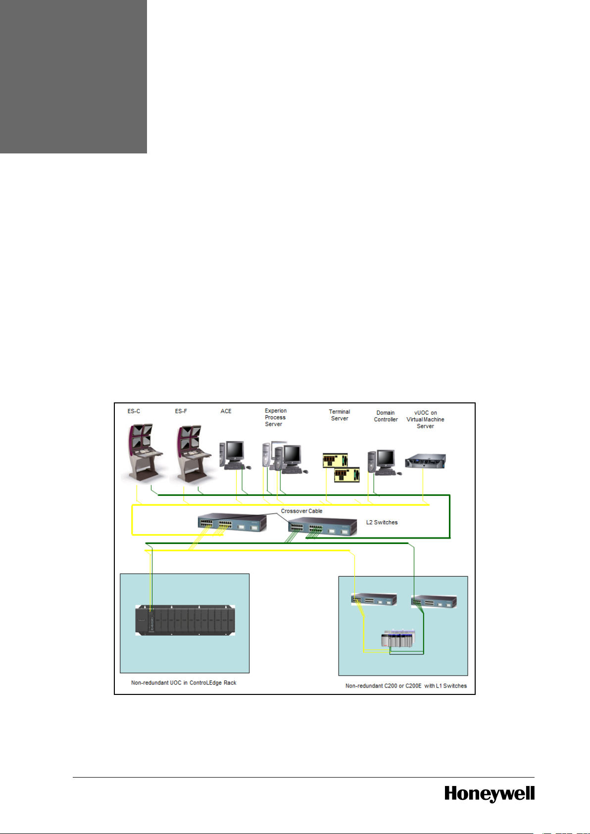
FTE connectivity is summarized in the following diagram which shows a non-redundant UOC rack
and a virtual machine server for a vUOC in the context of the following Experion nodes.
l Experion Process Server
l Experion Direct Station (ES-C)
l Experion Flex Station (ES-F)
l ACE
l Terminal Server
l Domain Controller
Figure 3.1 UOC Network Connectivity (Uplink FTE Network)
- 29 -

Chapter 3 - Networking
UOC utilizes an existing FTE network, native to Experion PKS. It has a dual connection to Level 2
Yellow and Green FTE switches. No third party firewalls are required.
The number of levels of FTE switches above the UOC may be one, as shown in the diagram above,
two or three.
vUOC’s deployment within an FTE network follows Experion guidance for virtual machines. For
further information, see the vUOC section in this document.
Like existing CEE controllers, UOC requires the presence of a Process Server to function within an
Experion system.
When connecting to FTE, the UOC CPM gets its IP address from the Experion BOOTP service
running on the Engineering Station node. Its IP address is constructed by combining the CPM’s
FTE Device Index with the subnet base address configured through Control Builder and known to
the BOOTP server. Rotary switches of the UOC CPM are located on the module and are used to set
the FTE Device Index. They must be set before the module is inserted into its slot.
ATTENTION
Ensure that the Device Index is set before you place a module in a rack.
Note that, in the special circumstance that a PLC CPM received from the factory is being converted
to a UOC CPM, considerations on IP addressing are different initially. For further information on
converting a PLC CPM to a UOC, see the Converting PLC CPM to UOC CPM section.
Care must be taken in the assignment of FTE device indices to a UOC’s rotary switches. In a
redundant controller rack, the left hand UOC must be assigned an odd numbered device index
while the right hand UOC must be assigned an odd + 1 device index. The odd + 1 position is
reserved and must not be used for other than redundant partner. Non-redundant UOCs must
always be assigned odd numbered device indices. For more information on how to set the FTE
device index see the FTE Device Index section.
The L2 FTE switches to which UOC connects are managed switches which must be configured
using the FTE Switch Configuration Tool. Any ports to which UOCs connect must be configured as
“Other Auto” using this tool. For further information on the FTE Switch Configuration Tool, see the
Switch Configuration Tool Users Guide_EPDOC-X246-EN-511A.pdf.
Except for specific considerations noted within this document, all FTE installation and
maintenance practices for the UOC and vUOC must be done in a fashion consistent with Experion
and FTE guidelines. For further information, see Fault Tolerant Ethernet Overview and
Implementation Guide EPDOC-XX37-en-511A.pdf, Fault Tolerant Ethernet Installation and Service
Guide EPDOC-XX36-en-511A.pdf, and Network and Security Planning Guide EPDOC-XX75-en511A.pdf.
3.2 Downlink I/O Network Topology
UOC supports direct connectivity to an I/O network through its downlink Ethernet ports, ETH3 and
ETH4.
The table below provides a description of various downlink topologies supported.
- 30 -

Chapter 3 - Networking
Topology Type Description Switch Types
Topology 1 HSR ring to 900 I/O. None
Topology 2 Non-redundant star to 900 I/O Generic
Topology 3 Redundant star (via PRP) to 900 I/O Generic
Topology 4 DLR direct connection to 900 I/O and
EIP devices
None
Topology 5 Non-redundant star to 900 I/O and EIP
devices
Generic and
Stratix
TM
ATTENTION
Uplink and downlink subnets must be unique. The Downlink subnet mask must be limited to
the number of addresses expected in that subnet.
For example, if a max of 64 addresses is expected, you could use a mask of 255.255.255.192.
Below sections provides detailed description of downlink topologies .
3.2.1 HSR Ring Topology with 900 I/O
High Availability Seamless Redundancy Protocol (HSR) is an industrial redundancy communication
protocol standardized by the International Electrotechnical Commission as IEC 62439-3 edition 2.
It allows system to overcome single network failure without affecting data transmission. It can be
applied to industrial Ethernet applications since it is independent of the protocols and provides
seamless failover.
HSR realizes active network redundancy by packet duplication over two independent networks that
operate in parallel.
When connecting to ControlEdge 900 I/O only, a redundant ring topology may be used. The ring
type is HSR (High Availability Seamless Redundancy). In this topology no third party redundancy
boxes are required. The UOC CPM connects directly, using its two downlink Ethernet ports.
Similarly, EPM modules connect directly using their two Ethernet ports. When a UOC downlink is
constructed in this fashion, it is not possible to connect third party I/O, Devices or PLCs. Only 900
I/O racks may be connected.
When connecting CPMs and EPMs into an I/O network ring, the numbered ports must be
connected so that odd numbered ports always connect to even numbered ports. This is shown in
the following diagram for the case of a redundant UOC rack with two UOC CPMs connecting to two,
4-I/O slot, non-redundant racks, each with its own EPM. Also shown are the CPM’s connection of
ETH1 to the A, Yellow FTE network tree and ETH2 to the B, Green FTE network tree. Note that
incorrect cabling will result in LAN ID Errors and reduced robustness. To clear the LAN ID errors
and the associated software, reset statistics.
- 31 -

Chapter 3 - Networking
Figure 3.2 Downlink I/O Network
Considerations for components that connect to a UOC’s downlink HSR ring network are
summarized in the following table.
- 32 -

Chapter 3 - Networking
Component
Type
Comments
ControlEdge
UOC CPM
The UOC CPM must be connected to the downlink I/O ring
such that even numbered ports always connect to odd
numbered ports. Important properties of UOC CPM
communications on the downlink network are configured on
the UOC Platform Block in Control Builder. This includes
configuration of the UOC DHCP server for assigning EPM IP
addresses. It also includes setting the Downlink Network
Configuration to Ring-HSR. For complete information on
configuring the downlink network properties on the UOC
Platform Block, see the UOC Platform Block section.
ControlEdge
900 I/O
Racks with
EPMs
An EPM must be connected to the downlink I/O ring such that
even numbered ports always connect to odd numbered ports.
Before it is inserted into its slot, the 100X rotary switch on the
EPM board must be set to indicate I/O network connectivity.
This is done by setting it to position 3. The IP address of the
EPM is assigned by the UOC CPM based on the module
number set on the 10X and 1X rotary switches. Ensure that the
values within the range of 1-12 are used, as these are the valid
values. This too must be set before the EPM is inserted into its
slot. For complete information see the ControlEdge 900 I/O
Device Connectivity section.
- 33 -

Chapter 3 - Networking
3.2.2 Redundant Star (PRP) Topology with 900 I/O
ATTENTION
The UOC does not support downlink network topologies containing both PRP and nonredundant connected devices. If your UOC downlink network connection type is configured
for redundant star, you should only connect PRP-capable devices to the downlink network.
Parallel Redundancy Protocol (PRP) is a data communication network standardized by the
International Electrotechnical Commission as IEC 61850 edition 2. It allows systems to overcome
single network failure without affecting data transmission. It can be applied to industrial Ethernet
applications since it is independent of the protocols and provides seamless failover.
PRP provides redundancy by sending two copies of the same frame over two independent
networks. A Redundancy Control Trailer (RCT) is added to each frame (which includes a sequence
number to support detection of duplicate messages so that one may be discarded.) It supports zero
failover time.
When connecting to ControlEdge 900 I/O only, either a non-redundant or redundant star topology
may be used. The network redundancy type is PRP (Parallel Redundancy Protocol). In this topology
no third party redundancy boxes are required. The UOC CPM connects directly, using its two
downlink Ethernet ports. Similarly, EPM modules connect directly using their two Ethernet ports.
When a UOC downlink is constructed in this fashion, it is not possible to connect third party I/O,
Devices or PLCs. Only 900 I/O racks may be connected.
An example of a UOC and two 900 I/O racks on a downlink, redundant, star network is shown in
the following diagram. Also shown are the CPM’s connection of ETH1 to the A, Yellow FTE network
tree and ETH2 to the B, Green FTE network tree.
Figure 3.3 Redundant Star Network
The UOC does not support star topologies which mix redundant and non-redundant connectivity.
Downlink star networks must be set up as exclusively redundant or exclusively non-redundant.
- 34 -

Chapter 3 - Networking
Component
Type
Comments
ControlEdge
UOC CPM
Important properties of UOC CPM communications on the
downlink network are configured on the UOC Platform Block in
Control Builder. This includes configuration of the UOC DHCP
server for assigning EPM IP addresses. It also includes setting
the Downlink Network Configuration to “Non-redundant” in the
case of a non-redundant star network or “Star-PRP” in the case
of a redundant star network. For complete information on
configuring the downlink network properties on the UOC
Platform Block, see the UOC Platform Block section.
ControlEdge
900 I/O
Racks with
EPMs
Before it is inserted into its slot, the 100X rotary switch on an
EPM board must be set to indicate I/O network connectivity.
For a non-redundant or redundant star network, this is done by
setting it to position 4. The IP address of the EPM is assigned
by the UOC CPM based on the module number set on the 10X
and 1X rotary switches. Ensure that the values within the range
of 1-12 are used, as these are the valid values. This too must be
set before the EPM is inserted into its slot. For complete
information see the ControlEdge 900 I/O Device Connectivity
section.
Unmanaged
Switches
900 I/O racks with EPM gateways have been qualified to
communicate with UOC through unmanaged switches.
Managed switches may not be used. For information on
qualified switches see the ControlEdge 900 Hardware and
Installation Guide.
Considerations for components that connect to a UOC’s downlink non-redundant or redundant
star network are summarized in the following table.
3.2.3 DLR Ring Topology with EtherNet/IP and 900 I/O devices
Device Level Ring (DLR) is layer 2 data link layer protocol that provides media redundancy, faster
network fault detection, and network fault resolution in a ring topology.
Advantages:
l DLR reduces the number of external components and associated cabling, which eases design
and installation. It also reduces the cost.
l When a ring breaks, DLR detects it and provides alternate routing of the data to help recover
the network at extremely fast rates.
l Line faults of bidirectional rings can be reconfigured quickly, as switching happens at a high
level, and thus the traffic does not require individual rerouting.
On network with only DLR devices, one device act as an active ring supervisor and other devices
form ring nodes. DLR network contain a maximum 50 IP address nodes(This is Honeywell
specification).
DLR network should have at least one node configured as ring supervisor. If there are multiple
nodes configured as supervisor, then the node with highest supervisor precedence value becomes
active supervisor, others will be backup Supervisors.
- 35 -

Chapter 3 - Networking
The active ring supervisor cyclically sends out Beacon Frames and Announce Frames on both
ports. They are received on one port of a ring node, processed and passed on to the next ring node
via the other port.
DLR ring topology which provides redundancy protection against a single network ring fault.
Installation and maintenance of a downlink EtherNet/IP network must be done in accordance with
the best practices of Ethernet networking in general and EtherNet/IP in particular.
In this topology, UOC connects directly to the ring through downlink ports ETH3 and ETH4. EPM
connects through their ETH1 port and ETH2 port directly to ring networks.
An example of a DLR Ring network is shown in the following diagram.
Figure 3.4 Downlink DLR Network
Installation and maintenance practices for the UOC’s downlink EtherNet/IP network generally
follow those described in the EtherNet IP User's Guide. Additional considerations for components
that connect to the EtherNet/IP network are summarized in the following table.
- 36 -

Chapter 3 - Networking
Component
Type
Comments
ControlEdge
UOC CPM
The UOC CPM connects to a downlink EtherNet/IP network
through its ETH3 and ETH4 ports. Important properties of
UOC CPM communications on the downlink network are
configured on the UOC Platform Block in Control Builder. This
includes configuration of the UOC DHCP server for assigning
EPM IP addresses. It also includes Downlink Network
Configuration to Non-redundant.
ControlEdge
900 I/O
Racks with
EPMs
When 900 I/O is used, the EPM in the I/O rack serves the role
of communication gateway into the I/O rack. When an EPM is
connected, ETH1 port and ETH2 port are directly connected to
an EtherNet/IP network. Before it is inserted into its slot, the
100x rotary switch on the EPM board must be set to indicate
the type of network connectivity in use. This is done by setting
it to position 4.
The IP address of the EPM is assigned by the UOC CPM based
on the module number set on the 10X and 1x rotary switches.
These switches must also be set before the EPM is inserted
into its slot.
For complete information on the use of ControlEdge EPM and
900 I/O, see ControlEdge 900 I/O section.
ControlLogix
PLC
UOC can communicate with Rockwell Allen Bradley
ControlLogix PLCs by passing instances of User Defined Types
(UDTs). References to ControLogix data are created in
Experion Control Builder with the aid of tag names provided by
the Matrikon Allen Bradley OPC server or by export of
ControlLogix tag names from the Rockwell Allen Bradley
Studio 5000 designer tool. ControlLogix PLCs on a UOC’s
downlink EtherNet/IP network must always use static IP
address assignments. For information on the configuration of
ControlLogix communications, see EtherNet IP User's Guide_
EPDOC-X399-en-511A.pdf.
EtherNet/IP
I/O and
Devices
UOC supports a set of EtherNet/IP devices with pre-populated
CEE block types in Experion Control Builder (CB). In addition,
CB provides the Parameter Definition Editor (PDE) tool which
allows for the integration of new EtherNet/IP I/O and devices
independent of Experion release. Although some third party
EtherNet/IP devices support IP address assignment from a
network resident DHCP server, this feature cannot be used
when the EtherNet/IP network connects to UOC. All device IP
addresses must be statically assigned. For further information,
see EtherNet IP User's Guide_EPDOC-X399-en-511A.pdf.
- 37 -

Component
Type
Comments
Allen Bradley
OPC Server
from
MatrikonOPC
The Rockwell Allen Bradley OPC Server from MatrikonOPC can
be installed on the Engineering Station in systems which
incorporate UOC. The Matrikon OPC Server enables one of two
methods whereby ControlLogix tag names can be used to
make UDT references in a UOC strategy. For further
information, see EtherNet IP User's Guide_EPDOC-X399-en-
511A.pdf.
Studio 5000
Logix
Designer
Software
Studio 5000 Logix Designer Software from Rockwell Allen
Bradley is used in conjunction with UOC configurations to
configure IP addresses of Rockwell Allen Bradley EtherNet/IP
devices. It can also be used to export a file which defines
ControlLogix tag names so that they can be used in Control
Builder to construct UDT data references from UOC. For
further information, see EtherNet IP User's Guide_EPDOC-
X399-en-511A.pdf.
Chapter 3 - Networking
3.2.4 Non-Redundant Star to 900 I/O and EIP Devices
ATTENTION
While using DLR (Device Level Ring) on Stratix 5700 Switch, DO NOT CONNECT a DLR
network to a Non-DLR port on the Switch. DLR should be connected only to the DLR ports
on the switch. Doing this will result in the entire downlink network going down. The recovery
is to only remove the DLR connection from the switch.
In addition to the DLR ring topology, the UOC can also connect to a non-redundant star
EtherNet/IP network through its ETH3 downlink port. This allows it to communicate
simultaneously with ControlEdge 900 I/O as well as EtherNet/IP-capable I/O, devices and PLCs.
Installation and maintenance of a downlink EtherNet/IP network must be done in accordance with
the best practices of Ethernet networking in general and EtherNet/IP in particular.
In this topology, CPMs connect through their ETH3 downlink port with ETH4 port disconnected.
EPMs connect through their ETH1 port with ETH2 port disconnected. An example is shown in the
diagram below.
- 38 -

Chapter 3 - Networking
Figure 3.5 UOC CPM to 900 I/O and EIP Devices
Installation and maintenance practices for the UOC’s downlink EtherNet/IP network generally
follow those described in EtherNet IP User's Guide_EPDOC-X399-en-510A.pdf for topology 2, “C300
Through EtherNet/IP”. Additional considerations for components that connect to the EtherNet/IP
network are summarized in the following table. ControlLogix PLCs and EtherNet/IP I/O and Devices
are equivalent to those for DLR ring networks.
- 39 -

Component
Type
Comments
ControlEdge
UOC CPM
The UOC CPM connects to a downlink EtherNet/IP network
through its ETH3 and ETH4port. Important properties of UOC
CPM communications on the downlink network are configured
on the UOC Platform Block in Control Builder. This includes
configuration of the UOC DHCP server for assigning EPM IP
addresses. It also includes Downlink Network Configuration to
Non-redundant.
ControlEdge
900 I/O
Racks with
EPMs
When 900 I/O is used, the EPM in the I/O rack serves the role
of communication gateway into the I/O rack. When an EPM is
connected to an EtherNet/IP network, its ETH1 port is
connected to the switch while its ETH2 port is left
disconnected. Before it is inserted into its slot, the 100x rotary
switch on the EPM board must be set to indicate the type of
network connectivity in use. This is done by setting it to position
4. The IP address of the EPM is assigned by the UOC CPM
based on the module number set on the 10X and 1x rotary
switches. These switches must also be set before the EPM is
inserted into its slot. For complete information on the use of
ControlEdge EPM and 900 I/O, see ControlEdge 900 I/O
Device Connectivity section.
Unmanaged
Switches
900 I/O racks with EPM gateways have been qualified to
communicate with UOC through unmanaged switches. EPMs
may not be connected through managed switches. For
information on qualified switches see ControlEdge 900 Platform
Hardware Planning and Installation Guide_ HWDOC-X430.pdf.
Stratix
Switches
EIP I/O, devices and PLCs may be connected to UOC through
qualified, Stratix managed switches. For further information on
how to deploy and configure Stratix switches, see EtherNet IP
User's Guide_EPDOC-X399-en-511A.pdf.
Chapter 3 - Networking
3.2.5 EtherNet/IP in Experion
Experion as a whole supports a variety of topologies for connecting to EtherNet/IP networks. For
additional information see EtherNet IP User's Guide_EPDOC-X399-en-511A.pdf.
To put UOC topologies into context, supported variations, including that of UOC, are summarized in
the following table.
- 40 -

#
Summary
Name
Connectivity Description
1 SCADA
Server To
EtherNet/IP
SCADA
Server
|
FTE Network
|
L2.5 or L3
Router
|
Ethernet
Link
|
EtherNet/IP-
capable
Switch
|
EtherNet/IP
Network
|
PLCs
The Experion SCADA Server supports
connectivity to Rockwell Allen Bradley
ControlLogix PLCs which are attached to
an EtherNet/IP network. The SCADA
Server connects to the L2 FTE network
which provides a path through an L2.5
or L3 Router and through nonredundant Ethernet links, to an
EtherNet/IP-capable, Stratix switch.
Access Lists of the router must be
configured as a security boundary
between the FTE and EtherNet/IP
networks.
2 UOC Direct
To
EtherNet/IP
UOC
|
EtherNet/IP-
capable
Switch
|
EtherNet/IP
Network
|
I/O, Devices
and PLCs
The UOC controller supports
connectivity to I/O, devices and Rockwell
Allen Bradley ControlLogix PLCs which
are attached to an EtherNet/IP network.
The UOC connects to a DLR ring
through its ETH3 (with ETH4 left
disconnected) downlink port.
Alternatively, it connects to a nonredundant star network. The IP subnet of
the UOC on its uplink FTE ports is
isolated from the IP subnet of the UOC
on its downlink EtherNet/IP port.
Honeywell ControlEdge 900 I/O can be
connected to the downlink EtherNet/IP
network along with third party I/O and
devices.
Chapter 3 - Networking
- 41 -

Chapter 3 - Networking
NOTE
Users who wish to use UOC with secure communications should be aware that considerable
planning and configuration is required in its setup. For further information, see section
Configuring a Secure Connection for Experion Integration.
- 42 -

CHAPTER
4
INSTALLATION
4.1 Hardware Considerations
The ControlEdge CPM (model # 900CP1-0200) can be used as a ControlEdge PLC or ControlEdge
UOC by programming in the corresponding firmware image.
To convert ControlEdge CPM (model # 900CP1-0200) to ControlEdge UOC, install the UOC
firmware image into the module.
The CPM Mode switch is not used by the ControlEdge UOC after initial firmware programming.
Therefore, once the module is programmed as ControlEdge UOC, the UOC label (see below) is
affixed over the CPM Mode Switch.
The odd device index UOC (default primary) must be inserted in the left-hand slot (slot 0). If there
is a backup module, it must be set to odd+1 and placed in the right-hand slot (slot 1). A nonredundant controller must not be placed in slot 1. For more information on how to set the FTE
device index, see the FTE Device Index section on page 52.
For more information, see ControlEdge 900 Platform Hardware Planning and Installation Guide_
HWDOC-X430.pdf.
4.2 Firmware Considerations
Installation and maintenance of UOC firmware entails several types of activities as follows:
l Converting a PLC CPM into a UOC CPM
l Upgrading a UOC CPM to a new firmware version
l Upgrading a UOC EPM to a new firmware version
l Upgrading a UOC UI/OM to a new firmware version
- 43 -

Chapter 4 - Installation
Firmware update and CPM conversion are done using an application called Firmware Manager.
For detailed information on using Firmware manager, see Firmware Manager User Guide_EPDOC-
X470.pdf.
4.2.1 Converting PLC CPM to UOC CPM
ControlEdge UOC and PLC are distinct controllers that can be deployed using a common family of
HW. For information on ControlEdge HW components see ControlEdge 900 Platform Hardware
Planning and Installation Guide_HWDOC-X430.pdf.
The ControlEdge Control Processor Module (CPM) is the central component which communicates
on its uplink ports with the Experion PKS system and on its downlink ports with I/O and devices.
The UOC'shardware and model number are identical to that of the ControlEdge PLC but its
firmware is different. The CPM is always shipped from the factory preloaded with PLC firmware. To
use a CPM in an Experion PKS system, it must first be converted into a UOC CPM by loading
firmware over a network connection.
Network connectivity is established by using an Ethernet port and IP address that conform to the
PLC’s communication methodology. The handling of Ethernet ports and IP addresses in a
ControlEdge PLC is different from that of Experion PKS. As a result, the PLC to be converted must
be placed in a system where it can communicate without needing to be a member of an FTE
community.
There are two possible ways of doing this as follows:
l Use a Bench system with a ControlEdge power supply and rack that can host a CPM.
l Use an Experion system with a ControlEdge power supply and rack or rack slot that can host a
CPM and is not being used for on-process control.
ATTENTION
l Once the PLC is converted into a UOC, it should not be reconnected to a PLC system
as it requires Experion PKS infrastructure to operate.
l The PLC’s ControlEdge Builder is not used to perform PLC-to-UOC conversion.
Manually attempting to load UOC firmware to a PLC-CPM with the PLC’s Control
Edge Builder may result in controller firmware corruption.
l UOC-to-PLC conversion is currently not supported. Manually attempting to load PLC
firmware to a UOC-CPM may result in controller firmware corruption.
l Do not install the PLC’s ControlEdge Builder software on either an Experion node
type or a Bench laptop or PC that has Firmware Manager installed. These
applications have similar controller communication infrastructure that are not
designed to co-exist resulting in Firmware Manager to module communication
breakage.
Converting Using Bench System
The main distinction of a Bench System it that it uses a laptop or PC that is not an Experion PKS
node type. The Bench laptop or PC requires a one-time install of Bench System Firmware Manager
from Experion PKS installation media. The special nature of this install is that it also installs the
UOC firmware in addition to the Firmware Manager application used to load the UOC firmware to
the PLC-CPM. Refer to Firmware Manager User Guide_EPDOC-X470.pdf for how to create a Bench
System laptop or PC.
To complete the Bench System, a ControlEdge controller rack with a power supply must be
procured. Either a redundant or non-redundant rack may be used. For information on rack types,
see ControlEdge 900 Platform Hardware Planning and Installation Guide_HWDOC-X430.pdf.
After the Bench system has been set up, it includes the components as shown here.
- 44 -

Figure 4.1 PLC CPM to UOC CPM Conversion using Bench System
Refer to Firmware Manager User Guide_EPDOC-X470.pdf for information on:
l How to create the Bench System laptop or PC.
l How to setup the Bench System PC and the PLC-CPM for conversion.
l How to perform the PLC-to-UOC conversion.
Convert PLC to UOC Using Experion System
Chapter 4 - Installation
Using Experion Equipment
When converting PLC to UOC within an Experion PKS system that is undergoing deployment, it is
not required create a Bench system laptop or PC. It is also not required to designate a specific rack
for use in a bench system. Instead, a controller rack with power supply that is being deployed
within the new system can be identified as a temporary host of the CPM(s) under conversion.
Careful consideration must be given to the creation of spare UOC CPMs before a temporary
conversion rack is put on-line. For further comments on spares, see section Spare UOC CPMs on
page 48.
Conversion using on Experion PKS Node and Experion PKS Rack
A PLC-CPM can be converted using an Experion PKS node that has an installation of Firmware
Manager together with an off-process ControlEdge controller rack that is part of the Experion
system. The necessary system components are summarized in the following diagram.
- 45 -

Chapter 4 - Installation
Figure 4.2 PLC CPM-UOC CPM Conversion using Firmware Manager on Experion System
Refer to Firmware Manager User Guide_EPDOC-X470.pdf for information on:
l How to setup the Experion PKS node and the PLC-CPM for conversion.
l How to perform the PLC-to-UOC conversion
Conversion using Bench Laptop and Experion PKS Rack
A PLC-CPM can be converted using a laptop that has an Bench installation of Firmware Manager
together with an off-process ControlEdge controller rack that is part of an Experion system. This
hybrid method is similar to using a Bench system but it is not required to deploy a separate
controller rack and power supply. The necessary system components are summarized in the
following diagram.
- 46 -

Chapter 4 - Installation
Figure 4.3 PLC CPM-UOC CPM Conversion using Firmware Manager on Laptop
Refer to Firmware Manager User Guide_EPDOC-X470.pdf forinformation on:
l How to create the Bench System laptop or PC.
l How to setup the Bench System PC and the PLC-CPM for conversion.
l How to perform the PLC-to-UOC conversion
Spare UOC CPMs
An important consideration in converting a PLC into a UOC is whether the site requires spares.
If spares are needed, a conscious decision must be made as to whether a spare is stored as a PLC
or as UOC.
If a spare is maintained as a PLC, and if a conversion Bench System is preserved for ongoing use,
then the CPM can be converted to a UOC at any time. However, the process of conversion is not
instantaneous. If it is desired to have a UOC available for quick use in an emergency, then it must
be converted ahead of time.If no bench system is set up to support future conversions and instead
a temporarily available controller rack is used, it is recommended to create the desired number of
spare UOC CPMs before the rack is put on-line. Doing so makes them available for quick use in
case of an emergency.
If additional UOC-CPMs are needed later and no bench system has been set up for conversion,
then a means will have to be found to use existing equipment. Given that a CPM is needed, the
system may have a controller rack which is already off-line. If so, that rack may be used to do the
conversion. If not, then a CPM will have to be taken off-line in order to do the conversion.
TIP
After the CPM has been converted into an UOC, please affix the UOC label over the CPM
mode switch as described in Hardware Considerations. This facilitates a quick UOC
replacement, as the label indicates that the unit has been converted to a UOC
- 47 -

Chapter 4 - Installation
4.2.2 Upgrading UOC CPM to New Firmware Version
The UOC Control Processor Module (CPM) uses two firmware images as follows:
l Boot Image: Also known as the Boot-Recovery Image, this firmware enables the CPM to boot
up, run diagnostics, communicate and support firmware load. It does not enable the CPM to
perform its control mission. The existence of the Boot Image insures that the CPM can always
allow its firmware to be reloaded, even if the Application Image is absent or non-functional.
l Application Image: Also known as the Application-Product Image, this firmware provides all
functionalities of the Boot Image as well all enablers required for the control mission. The
Application Image allows the CPM to boot up without assistance from the Boot Image. Under
normal operation, the CPM executes out of its Application Image only. Execution enters the
Boot Image only in the event of a system failure or during the process of firmware load.
After a CPM has been converted from PLC firmware to UOC firmware, updates are done on an
Experion system using Firmware Manager. Either the Application Image, the Boot Image, or both
can be loaded.
When updating UOC firmware, only one Firmware Manager client at a time may load firmware to
the UOC. In addition, the total number of Firmware Manager clients that may connect to a UOC at
one time, for monitoring node status or for loading firmware, is limited to 4.
The UOC must be running in the application (RDY) to upgrade the recovery image and in recovery
(ALIVE) to upgrade the application. Synchronization must be disabled before attempting firmware
upgrade. The firmware manager will place the UOC in the proper state for loading each image.
Care must be taken when upgrading the firmware of a redundant UOC pair. As of R511.1, onprocess firmware upgrade of a redundant UOC is not supported. The controller must first be taken
off-line by setting the CEE state to Idle. In addition, synchronization between the primary and
secondary partners must be disabled so that the UOC does not attempt to switchover during the
firmware upgrade process. Upgrade the firmware in the backup, then the firmware in the primary.
New firmware images are frequently received with major Experion releases.They can also be
received via download from the HPS website.
For instructions on how to load firmware using Firmware Manager see Firmware Manager_EPDOC-
X404.pdf.
4.2.3 Upgrading UOC EPM to new Firmware Version
When updating to a new release, always update UOC before updating EPM.
You must always use the firmware from the Experion media. The firmware that is purchased from
ControlEdge PLC must not be used. If you have purchased the product from ControlEdge PLC, you
must perform the following procedure to upgrade the firmware.
Like the CPM, the UOC EPM uses two firmware images, a Boot Image and an Application Image.
The two images play the same role within the EPM as do the corresponding images in the CPM.
Unlike the CPM, these firmware images are of the same type as those used by the ControlEdge
PLC, though they may be at different version levels.
NOTE
To know the latest EPM Firmware version, refer to the SCN document.
NOTE
When loading firmware to an EPM, the firmware obtained with the Experion installation
- 48 -

Chapter 4 - Installation
must always be used. Firmware that might have been obtained from a ControlEdge PLC
installation must not be used.
NOTE
Update EPM only after updating UOC (if needed).
For a UOC system, updates of EPM firmware are done on an Experion system using Firmware
Manager.
The load of firmware to EPM works by sending the firmware packets to the CPM which then
forwards them to the EPM. The parent CPM of an EPM must be known to Firmware Manager in
order for the load to take place. Firmware Manager supports a means whereby the EPM children of
a CPM can be specified.
When updating EPM firmware, only one Firmware Manager client at a time may load firmware to
the EPM through its parent UOC.In addition, the total number of Firmware Manager clients that
may connect to a UOC at one time, for monitoring node status or for loading firmware, is limited to
4.
New images are sometimes received with major releases of Experion. They can also be received via
download from the HPS website.
For instructions on how to load firmware using Firmware Manager, see Firmware Manager_
EPDOC-X404.pdf.
Upgrading the UOCEPM
The procedure used to upgrade EPM firmware varies depending on the downlink network protocol
in use. In one case, the selected protocol must be temporarily changed during the course of
upgrade. In some cases, network redundancy must be temporarily disabled during the course of
upgrade.
Procedure to upgrade EPM Firmware in a UOC Nonredundant or PRP network:
NOTE
For PRP networks, redundant network connectivity should be left disconnected during the
process of EPM firmware upgrade.
1. Set the 100x switch position of the EPM as per the desired UOC downlink network protocol
(position 4 for Nonredundant or PRP).
2. Connect Ethernet Port 1 of the EPM to the UOC download link network, leaving Ethernet Port
2 disconnected.
3. Insert the EPM into the IO rack, causing it to reboot.
4. Upgrade EPM Firmware using Firmware Manager.
Procedure to upgrade EPM Firmware in a UOC HSR network:
1. Set the 100x switch position of the EPM as per the desired UOC downlink network protocol
(position 3 for HSR).
2. Connect both Ethernet Port 1 and Ethernet Port 2 of the EPM to the UOC download link
network.
3. Insert the EPM into the IO rack, causing it to reboot.
4. Upgrade EPM Firmware using Firmware Manager.
Procedure to upgrade EPM Firmware in a UOC DLR network:
- 49 -

Chapter 4 - Installation
NOTE
For PRP networks, redundant network connectivity should be left disconnected during the
process of EPM firmware upgrade.
1. Temporarily set the 100X switch position of the EPM to 4 (PRP protocol).
2. Connect Ethernet Port 1 of the EPM to the UOC downlink network, leaving Ethernet port of
EPM disconnected.
3. Insert the EPM into the IO rack, causing it to reboot.
4. Upgrade EPM Firmware using Firmware Manager.
5. Change the 100x switch to position 5 (DLR).
6. Insert the EPM into the IO rack, causing it to reboot.
7. Connect the Ethernet Port 1 and Port 2 of the EPM to the UOC downlink network, closing the
DLR ring.
For detailed instructions on the use of Firmware Manager see the Firmware manager User Guide.
For information on which version of EPM firmware is supported in the current release see the
Software Change Notice (SCN).
4.2.4 Upgrading UOC UIOM to new Firmware Version
When updating to a new release, please update UOC and EPM before updating UIOM.
Like the CPM and the EPM, the UOC UI/OM uses two firmware images, a Boot Image and an
Application Image. The two images play the same role within the UI/OM as do the corresponding
ones in the EPM and CPM.
However, in the case of the UI/OM, the Boot Image rarely changes but both images are loadable.
Like the EPM, the UI/OM has an Application Image which is of that same type as that used by the
ControlEdge PLC, though they may be at different version levels.
NOTE
When loading firmware to a UI/OM, the firmware obtained with the Experion installation
must always be used. Firmware that might have been obtained from a ControlEdge PLC
installation must not be used.
NOTE
Update I/OM only after updating UOC and EPM (if needed).
For a UOC system, updates of UI/OM firmware are done on an Experion system using Firmware
Manager.
The load of firmware to UI/OM works by sending the firmware packets to the CPM which then
forwards them to the EPM which in turn forwards them to the UI/OM. The parent EPM of a UI/OM
must be known to Firmware Manager in order for the load to take place. Firmware Manager
supports a means whereby the UI/OM children of an EPM can be specified.
When updating UI/OM firmware, only one Firmware Manager client at a time may load firmware to
the UI/OM through its parent UOC. In addition, the total number of Firmware Manager clients that
may connect to a UOC at one time, for monitoring node status or for loading firmware, is limited to
4.
- 50 -

Chapter 4 - Installation
New Application Images are sometimes received with major releases of Experion. They can also be
received via download from the HPS website.
For instructions on how to load firmware using Firmware Manager, see Firmware Manager_
EPDOC-X404.pdf.
4.2.5 Firmware and Software Upgrade Considerations for vUOC
The Unit Operations Controller and virtual Unit Operations Controller (vUOC) are equivalent with
respect to most major functionalities. However, when it comes to platform maintenance activities
such as firmware load of the controller itself, they are different.
vUOC is deployed as a virtual machine by importing a .ova file into a virtualization hypervisor. It has
no firmware or firmware load capabilities as such. Thus, updates to vUOC software are done by
deploying a new .ova file rather than loading new firmware to a CPM.
UOC-CPM and vUOC are designed to use the same communication channels to support load of
firmware to EPM and UI/OM. Each receives packets sent by Firmware Manager and forwards them
to the target module. However, in the Experion R511 release, the vUOC capabilities to support EPM
and UI/OM firmware load are not yet enabled. Firmware Manager is used to load firmware to CPM
and UI/OM.
For further information on how vUOC software is deployed see the vUOC section.
4.2.6 Additional Maintenance Activities in Firmware Manager
In addition to conversion of a PLC CPM into a UOC CPM, update of CPM firmware, update of EPM
firmware and update of UI/OM firmware, Firmware Manager supports maintenance activities
unrelated to firmware load. Key among them is the ability to upload diagnostic data from a CPM
which is not operating properly. For information on diagnostic data upload using Firmware
Manager, see Firmware Manager_EPDOC-X404.pdf.
- 51 -

CHAPTER
5
CONFIGURATION
5.1 Configuration Studio
Configuration Studio is the central location from which you can access engineering tools and
applications to configure your Experion system. When you choose Control Strategy in the
Configuration Explorer tree and then choose the task Configure a Control Strategy, Control
Builder is launched so you can configure ControlEdge 900 I/O hardware modules and build the
process control strategies for your system.
5.2 Define and add assets in your enterprise model
If you are using Enterprise Model Builder (EMB) application to create an asset model of your
system, assets that represent UOC controllers can be created and added to your model following
the same procedures for creating assets and alarm groups. See the Enterprise Model Builder User's
Guide for details.
5.3 Control Building
For information on Control Builder, see the Control Building User’s Guide.
5.4 Specifying a Time Server
UOC requires a reference source for time in order to power up and normally operate, but limited
controller operation can be achieved in cases where system time is not available. Connection to
the time source is made at controller start up.
Network Time Protocol synchronizes the controllers and other nodes to Coordinated Universal
Time (UTC). The time source is given an IP address so that controllers and other nodes can access
time. See the Setting system preferences in the Control Building User's Guide for more information
about setting IP addresses.
Precision Time Protocol (PTP) does not require any server configuration. If a PTP server is present
on the subnet and PTP is enabled in the module, it will work.
5.5 FTE Device Index
The FTE Device Index uniquely identifies the controller on the FTE Network. The FTE Device Index
is configured in two places. First, the CPM rotary switches are used to set the FTE device index of
the UOC. Second, Experion PKS Control Builder is used to configure the FTE Device Index in the
UOC Platform Function Block.
Control Builder enforces the following:
- 52 -

Chapter 5 - Configuration
l The primary controller (of a redundant controller pair) always configured with an odd
numbered Device Index.
l A non-redundant controller is only configured with an odd numbered Device Index.
l The secondary controller of a redundant controller pair is configured with the even Device
Index that is consecutive with its primary partner’s Device Index (i.e. primary controller Device
Index plus 1).
Set the Device Index (FTE DEVICE INDEX) by turning the three rotary decimal switches (range 001
to 509). The leftmost switch on top is used for setting the hundreds digit, the right switch on top is
used for setting the tens digit, and the bottom switch sets the ones digit.
Example: For a redundant pair, the primary and secondary indexes respectively could be 001, 002;
111, 112; 507, 508 and so on. In a non-redundant setup, the index could be: 001 or 111 or 507 and
so on.
Failure to replicate the UOC Device Control Index according to their Control Builder configured
Device Indexes will lead to failure in establishing Control Builder - controller communication
thereby preventing configuration load.
For in-rack redundancy, the left controller is recommended to be configured as the odd device
index and the right controller as the event device index (of the consecutive device index pair).
Redundancy communication between a pair of redundant UOC is not possible if their device
indices are not set to a consecutive odd/even pair.
In the non-redundant case, the odd+1 address is reserved for future redundancy. It must not be
assigned to any other function.
5.6 Creating UOC Platform block
5.6.1 Method 1: Using the File Menu
Using the File menu, select File > New > Controllers > UOC - Control Edge Unit Operations
Controller.
5.6.2 Method 2: Using the Project Assignment Panel
Using the Project Assignment panel context menu, right-click in the white area of the panel and
select New > Controllers > UOC - Control Edge Unit Operations Controller.
- 53 -

5.7 UOC Platform Block
The UOC Platform Block or “UOC Block” presents parameters which describe key characteristics of
the UOC CPM platform and allows a subset of those parameters to be configured. The UOC Block is
configured within Experion Control Builder along with all other elements of UOC configuration.
Configuring and loading the UOC Block is one of the first steps required to make a UOC HW set
known to the Experion system.
The following sections describe configuration forms of the UOC Block that are accessible from
within Control Builder. Like all Control Builder forms, these can be examined under two different
views. One is the Project View which allows for configurable parameters to be assigned values
before load of the UOC Block. The other is the Monitoring View which allows parameter values of
the UOC Block to be read from the controller while it is running.
For a general introduction to the use of Experion Control builder in configuring and monitoring
platform blocks, CEE blocks, Control Modules, Sequence Control Modules and other types of
loadable objects, see Control Builder User’s Guide_EPDOC_XX19_en-511A.pdf.
Chapter 5 - Configuration
- 54 -

Tab Description
Main tab
This tab is used to configure the UOC block. This tab also displays important
state information and supports generation of commands to the CEE via
parameter writes. The screenshots below show descriptions and names of
each parameter that appears on the configuration form of the Main tab. For
further information about each parameter, consult the Control Builder
Parameter Reference Guide_EPDOC-XX18-en-511A.pdf.
Take note of the following considerations when configuring the Main tab of
the UOC Platform block.
The DHCP address range used by EPMs on the downlink is configured from
the “Downlink Address Configuration” section. The UOC’s DHCP server assigns
IP addresses based on the module number set on the 10X and 1X rotary
switches of the EPM board. The address range can cover up to 12 addresses
with EPM module number 1 being mapped into the start address of the range.
If an EPM module number is set outside the DHCP address range, it will not
receive an IP address and will not be able to communicate. Care must be taken
to ensure that the address range has been configured correctly before going
on process. If the address range needs to be changed, it can only be done by
reloading the UOC platform block while the UOC is off process.
The Connection Type configured in the “Downlink Network Configuration”
section changes the way the UOC behaves with respect to downlink network
redundancy. For more information refer to to 3.2 Downlink I/O Network
Topology.
NOTE
Two screens in all the following tabs show Parameter Names”
checked/unchecked.
Chapter 5 - Configuration
- 55 -

Chapter 5 - Configuration
Tab Description
System Time tab
This tab provides information about the UOC’s time configuration. The “System
Time” and “System Time Synchronization Status” subgroups on this tab
provide current controller system time and indicate the synchronization time
source and the status of that source. The “NTP Status” and “Precision Time
Protocol” subgroups provide statistics related to time synchronization with
NTP and PTP servers, along with their status.
The screenshots below show descriptions and names of each parameter that
appears on the configuration form of the System Time tab. For further
information about each parameter, see Control Builder Parameter Reference
Guide_EPDOC-XX18-en-511A.pdf.
Tab Description
Statistics tab
This tab shows a variety of statistics parameters that can be monitored to learn
about the processing load and operating conditions of the UOC. Such
information includes CPU utilization, hardware temperature and
communications sub- system (CDA) statistics. The screenshots below show
descriptions and names of each parameter that appears on the form of the
Statistics tab. For further information about each parameter, see Control
Builder Parameter Reference Guide_EPDOC-XX18-en-511A.pdf.
- 56 -

Tab Description
Hardware Information tab
This tab contains data describing the UOC module including firmware and
hardware version information. The parameters provided here are used for
maintenance, troubleshooting and problem description purposes. All
parameters on this form are read-only. Note that the Hardware Information
Tab displays several parameters related to UOC retention restart. These are as
follows. The screenshots below show descriptions and names of each
parameter that appears on the form of the Hardware Information tab. For
further information about each parameter, see Control Builder Parameter
Reference Guide_EPDOC-XX18-en-511A.pdf.
Retention Data Attendance
The RETENDATAATTND parameter has enumeration values Absent and Present
to indicate when retention data does not exist and retention data has been
saved. When set to Present, the RETENTSAVETIME parameter indicates the
time when the retention data was saved.
Retention Data Save Time
When RETENDATAATTND is Present, RETENSAVETIME indicates the last time
retention data was saved.
Retention Restart Veto Reason
Initialized once on startup to indicate the reason why the controller has vetoed
retention startup.
l None – Retention restart was not vetoed.
l DeviceIndexChanged – Retention restart was vetoed due to a change in
the controller’s device index setting.
l BaseIpAddrChanged – Retention restart was vetoed due to a change in
Base IP Address (and/or Base IP Mask). A change in base IP Address
implies the controller was redeployed in a different Experion cluster
without changing its Device Index.
l UnsupportedHardware – The controller hardware is defective or was not
properly initialized when it was manufactured.
Chapter 5 - Configuration
- 57 -

Chapter 5 - Configuration
Tab Description
l RetentionMediaError – Retention restart was vetoed due to invalid
retention memory detected by the controller. Possible causes for invalid
retention memory are as follows:
l SD card missing.
l SD card not inserted fully or not inserted properly.
l SD card format not recognized.
l SD card locked for read-only access.
l RetentionDataAbsent – Retention data was not saved.
l RetentionDataCorrupt – Retention data exists but did not pass controller
validation.
l RetentionDataExpired – The retention data was saved more than 48 hours
ago.
l RedundancyRoleSecondary – The retention data is discarded when the
controller is in the secondary redundancy role.
l TimeSyncNotConfigured – Time-sync is not configured on the controller.
Without time-sync configured, the controller cannot determine the age of
the retention data and to be safe, the retention data is discarded.
l TimeSyncTimeout – Time-sync is configured on the controller, but the
controller timed-out waiting for the time-sync server response. Without
time-sync configured, the controller cannot determine the age of the
retention data and to be safe, the retention data is discarded.
- 58 -

Tab Description
FTE tab
This tab contains statistics related to Fault Tolerant Ethernet (FTE)
communications and performance. The FTE tab features parameters
associated with the MAC Address Resolution Table (MART) which deals with
on- line media access control (MAC) address mapping. All parameters of the
FTE tab are read-only. The screenshots below show descriptions and names of
each parameter that appears on the form of the FTE tab. For further
information about each parameter, see Control Builder Parameter Reference
Guide_EPDOC-XX18-en-511A.pdf.
Chapter 5 - Configuration
- 59 -

Tab Description
Downlink tab
This tab shows statistics and configuration parameters related to downlink
Ethernet communications.
For DLR, the Primary defaults to ring supervisor. The supervisor parameters
are exposed and default to values appropriate for, when UOC is the only
supervisor.
The supervisor precedence must be configured as highest precedence value so
that UOC takes the active supervisor role.
NOTE
l Downlink connection type can be changed from disabled to any
Downlink connection type like HSR, PRP, Non-redundant start.
This can be done on-process.
l The supervisor parameters are exposed and default to values
appropriate for when UOC is the only supervisor.
l Changing Downlink connection type from HSR/ PRP to DLR
would require an off-process and a restart is required.
l Downlink connection type can be changed from disabled to any
Downlink connection type like HSR, PRP, Non-redundant start.
This can be done onprocess.
l Changing Downlink connection from disabled to DLR would
require an off-process and a restart is required.
NOTE
If a Rapid Fault condition is detected, manual intervention is needed
to clear the state in Control Builder or Station. This fault occurs when
a series of rapid ring faults is detected, typically with a ring fault and
recovery cycle of 5 times in 30 seconds.
NOTE
To detect the fault location in a ring network, you must clear the first
fault in the ring and click Update Locate fault .This will re-initiate the
search and locate the next fault location in the ring, if any.
For further information about each parameter, see Control Builder Parameter
Reference Guide_EPDOC-XX18-en-511A.pdf.
Chapter 5 - Configuration
- 60 -

Tab Description
Tab Description
UDP/TCP tab
This tab displays statistics related to open UDP and TCP connections
associated with this UOC controller. All parameters on this form are read-only.
The screenshots below show descriptions and names of each parameter that
appears on the form of the UDP / TCP tab. For further information about each
parameter, see Control Builder Parameter Reference Guide_EPDOC-XX18-en-
511A.pdf.
Chapter 5 - Configuration
- 61 -

Chapter 5 - Configuration
Tab Description
IP/ICMP tab
This tab displays statistics related to IP and ICMP protocol messages
associated with (i.e. originating in or received by) this UOC controller. These
types of messages are generally associated with maintenance and status
operations on the network. All of the parameters shown on this form are
read-only.
The screenshots below show descriptions and names of each parameter
that appears on the form of the IP / ICMP tab. For further information
about each parameter, see Control Builder Parameter Reference Guide_
EPDOC-XX18-en-511A.pdf.
- 62 -

Tab Description
Soft Failures tab
This tab indicates which soft failure conditions, if any, are active. Users
typically navigate to this form after receiving a general indication that at
least one soft failure is present, such as a soft failure notification. All
parameters shown on this form are read-only.
The screenshots below show descriptions and names of each parameter
that appears on the form of the Soft Failures tab. For further information
about each parameter, see Control Builder Parameter Reference Guide_
EPDOC-XX18-en-511A.pdf.
NOTE
The HSR/PRP LAN ID soft failure is only cleared by resetting
statistics (See Statistics tab). This will clear the LAN ID error
counts and the soft failure.
Chapter 5 - Configuration
- 63 -

Chapter 5 - Configuration
Tab Description
Security tab
This tab allows for the disabling of optional protocols. As an additional
security measure, Honeywell recommends disabling protocols which are
not required in a particular UOC deployment. Most UOC protocols are
required for proper function in all deployments. HART / IP can be disabled
when not in use. HART/IP must be enabled when FDM is used.
- 64 -

Tab Description
Server History tab
This tab is common to all configuration forms for tagged blocks in Control
Builder. This form allows users to specify individual parameters of the
block which are to be collected for history recording.
ATTENTION
The configuration settings you make for Server Load Options on
the System Preferences dialog determine whether or not the data
entered on the Server History tab is loaded to the Experion Server.
See Control Building User Guide for information about setting
system preferences.
The screenshots below show descriptions and names of each parameter
that appears on the form of the Server History tab. For further information
about each parameter, see Control Builder Parameter Reference Guide_
EPDOC-XX18-en-511A.pdf.
Chapter 5 - Configuration
- 65 -

Chapter 5 - Configuration
Tab Description
Server Displays tab
This tab is common to all configuration forms for tagged blocks in Control
Builder. It allows users to associate Point Detail, Group Detail, Associated
and Trend displays with the block.
The screenshots below show descriptions and names of each parameter
that appears on the form of the Server Displays tab. For further information
about each parameter, see Control Builder Parameter Reference Guide_
EPDOC-XX18-en-511A.pdf.
- 66 -

Tab Description
Control Confirmation tab
This tab is common to all configuration forms for tagged blocks in Control
Builder. If you have an optional Electronic Signature license, you can
configure electronic signature information for the tagged block through
this tab on the block's configuration form in Control Builder. Please refer
to the Server and Client Configuration Guide for information about the
data on this tab.
The Electronic Signature function aligns with the identical Electronic
Signatures function that is initiated through Quick Builder and Station for
Server points. When this block is loaded to a controller, its control
confirmation configuration (electronic signatures) is also loaded to the
Server. This means you can view the control confirmation configuration for
this tagged object in Station and also make changes to it. If you make
changes through Station, you must initiate an Upload or Upload with
Contents function through the Controller menu in Control Builder for the
object in the Monitoring tab to synchronize changes in the Engineering
Repository Database (ERDB). The screenshots below show descriptions
and names of each parameter that appears on the form of the Control
Confirmation tab. For further information about each parameter, see
Control Builder Parameter Reference Guide_EPDOC-XX18-en-511A.pdf.
Chapter 5 - Configuration
- 67 -

Chapter 5 - Configuration
Tab Description
QVCS tab
This tab is common to all configuration forms for tagged blocks in Control
Builder. If you have a Qualification and Version Control System (QVCS)
license, this tab shows current QVCS information for the selected UOC
block. Please refer to the Qualification and Version Control System User's
Guide for more information about the data on this tab The screenshots
below show descriptions and names of each parameter that appears on the
form of the QVCS tab. For further information about each parameter, see
Control Builder Parameter Reference Guide_EPDOC-XX18-en-511A.pdf.
NOTE
It is mandatory to use the Revert Label feature for template based EIP I/OMs (E.g:
Generic Device Modules or Generic I/O Modules) to perform QVCS Revert operations.
Failure to apply a common label to the template and the corresponding instance will
lead to a deadlock situation if performing Revert Version operations. It is mandatory that
the template and the corresponding instance must have the same version label. This
can be achieved by applying the same label to both the template and its corresponding
instance.
- 68 -

Tab Description
Identification tab
This tab is common to all configuration forms for tagged blocks in Control
Builder. It allows users to record information about the intended purpose
and maintenance history of the block.
The screenshots below show descriptions and names of each parameter
that appears on the form of the Identification tab. For further information
about each parameter, see Control Builder Parameter Reference Guide_
EPDOC-XX18-en-511A.pdf.
Chapter 5 - Configuration
5.8 Secondary UOC Platform Block
The Secondary UOC controller block is available when the ‘Module is redundant’ (MODISREDUN)
check box is checked on the Primary UOC configuration form Main tab. The Secondary UOC
configuration form contains the same tabs and parameters as the primary with the exception of a
few parameters on the Main and Redundancy tabs. The differences are described in the following
paragraphs.
- 69 -

Chapter 5 - Configuration
Tab Description
Main tab
This tab of the Secondary UOC Block configuration form does not contain the
‘Module is redundant’ or ‘Secondary Tag Name’ fields. All other parameters
contained on the Primary's Main tab are present on the secondary's Main tab.
Parameters in the Advanced Configuration subgroup are copied from the
primary block to the secondary block and are view only on the secondary's
form.
NOTE
Two screens in all the following tabs show Parameter Names”
checked/unchecked.
Redundancy tab
This tab of the Secondary UOC block contains the parameter ‘Last Block
Migrated’ (LASTOPMNAME) which is not applicable on the Primary UOC block.
5.9 CEE Function Block
The CEE function block is created when a new UOC controller block is created and configured in
the CB Project tree. The following sections illustrate the Control Builder forms of each tab of the
CEE block. For more details about these parameters, see Control Builder Parameter Reference_
EPDOC-XX18-en-511A.pdf.
NOTE
The UOC’s CEE block is sometimes called the “CEE UOC” block to highlight the fact that it
has some differences from the CEE block of other controllers such as the C200, C200E,
C300. However, its major characteristics are consistent with those of other CEE controllers.
- 70 -

Tab Descripton
Main tab
This tab is used for the configuration of the CEE block. The configuration steps
are defined in Control Building User’s Guide (Control Building User’s Guide_
EPDOC-XX19-en-511A.pdf). This tab also displays important state information
and allows the store of some runtime parameters. The screenshots below show
descriptions and names of each parameter that appear on the configuration
form of the Main tab. For further information about each parameter, see
Control Builder Parameter Reference_EPDOC-XX18-en-511A.pdf.
For secondary platform block, refer section Secondary UOC Platform Block.
NOTE
Two screens in all the following tabs show Parameter Names”
checked/unchecked.
Show Parameter Names” checked/unchecked
Chapter 5 - Configuration
- 71 -

Chapter 5 - Configuration
Tab Description
Peer Configuration tab
This tab contains information about user-defined peer connections for the
CEE block. The Peer Configuration tab displays information about peer
connections established by this CEE. It allows a global default subscription
period for peer reads to be established and also allows different subscriptions
to be established for particular peer environments. The screenshots below
show descriptions and names of each parameter that appear on the form of
the Peer Configuration tab. For further information about each parameter, see
Control Builder Parameter Reference_EPDOC-XX18-en-511A.pdf.
Tab Description
Statistics tab
This tab displays a variety of statistical information characterizing different
types of communication mechanisms used by the CEE. The screenshots below
show descriptions and names of each parameter that appear on the form of
the Statistics tab. For further information about each parameter, see Control
Builder Parameter Reference_EPDOC-XX18-en-511A.pdf.
- 72 -

Tab Description
CPU Loading tab
This tab is organized as a set of 4 arrays, each one indexed by the number of
CEE processing cycles, 0 through 39. Statistics values which characterize a
particular cycle are shown at its corresponding cycle number.
The first column shows average CPU used for each cycle. The second shows,
for each cycle, the maximum CPU usage since the time of last UOC statistics
reset. The third and fourth columns together show the quantity of data sent
from primary to secondary, for the particular cycle, as part of redundancy
synchronization communication. Each column reflects a different redundancy
synchronization mechanism.
Each array also shows a value for index 40, indicating the value normalized
over cycles 0 through 39. In the case of CPU cycle average array, element 40
shows the average across all cycles. In the case of the 3 maximum arrays,
element 40 shows the maximum across all cycles.
The screenshots below show descriptions and names of each parameter that
appears on the form of the CPU Loading tab. For further information about
each parameter, see Control Builder Parameter Reference_EPDOC-XX18-en-
511A.pdf.
Chapter 5 - Configuration
- 73 -

Chapter 5 - Configuration
Tab Description
CPU Overruns tab
This tab is organized as a set of 2 arrays, each one indexed by the number of
CEE processing cycles, 0 through 39. Statistics values which characterize a
particular cycle are shown at its corresponding cycle number.
The first column shows the count of CEE processing cycle overruns that have
occurred so far in the current hour. The second column shows the count of
CEE processing cycle overruns that occurred in the previous hour. The current
hour counts in the first column accumulate until the end of the hour and then
get transferred into the second column. Start and end times for the hourly
intervals are not correlated with wall clock time.
Each array also shows a value for index 40, indicating the sum of all overrun
counts over cycles 0 through 39.
The screenshots below show descriptions and names of each parameter that
appear on the form of the CPU Overruns tab. For further information about
each parameter, see Control Builder Parameter Reference_EPDOC-XX18-en-
511A.pdf.
- 74 -

Tab Description
EtherNet/IP Statistics tab
This tab shows the IP address and connection status of each UOC downlink
connection to an EtherNet/IP device. For bridged connections to modular I/O
stations, it also shows the slot number corresponding to each I/O module. This
form displays only read-only parameters.
The screenshots below show descriptions and names of each parameter that
appear on the form of the EtherNet/IP Statistics tab. For further information
about each parameter, see Control Builder Parameter Reference_EPDOC-XX18-
en-511A.pdf.
Tab Description
CLX Statistics tab
This tab presents information about UOC’s downlink EtherNet/IP
communication with ControlLogix PLCs. Information displayed includes
counts of tagged data reads and writes initiated by the UOC, IP addresses of
connected PLCs, status of each PLC connection and transactions per second
to each PLC. This form shows only read-only parameters.
The screenshots below show descriptions and names of each parameter that
appear on the form of the CLX Statistics tab. For further information about
each parameter, see Control Builder Parameter Reference_EPDOC-XX18-en-
511A.pdf.
Chapter 5 - Configuration
- 75 -

Chapter 5 - Configuration
Tab Description
Batch tab
This tab shows information related to batch processing being carried out by
the UOC. This includes configurable parameters for Batch Event Settings and
Activity Configuration. It also includes 4 read-only arrays which indicate
whether any Control Recipe cycles have been skipped and for what period of
time.
The screenshots below show descriptions and names of each parameter that
appear on the form of the Batch tab. For further information about each
parameter, see Control Builder Parameter Reference_EPDOC-XX18-en-
511A.pdf.
Tab Description
Memory tab
This tab presents information on UOC memory usage within CEE’s user
memory pool. Of most interest to end users are statistics indicating used and
free memory. These are shown in units of both kilobytes and bytes. Also shown
are all descriptor counts and block counts which provide information related
to internal memory management within CEE.
The screenshots below show descriptions and names of each parameter that
appear on the form of the Memory tab. For further information about each
parameter, see Control Builder Parameter Reference_EPDOC-XX18-en-
511A.pdf.
- 76 -

Tab Description
Peer Connections tab
This tab contains data indicating the number of peer connections for both
initiator and responder types between this UOC controller and other peercapable nodes. All parameters on this tab are read-only.
The screenshots below show descriptions and names of each parameter that
appear on the form of the Peer Connections tab. For further information about
each parameter, see Control Builder Parameter Reference_EPDOC-XX18-en-
511A.pdf.
Tab Description
Peer Communications tab
This tab contains information about peer connections. It gives statistics for
connections initiated by the CEE block and connections to which the CEE
responds. The screenshots below show descriptions and names of each
parameter that appear on the form of the Peer Communications tab. For
further information about each parameter, see Control Builder Parameter
Reference_EPDOC-XX18-en-511A.pdf.
Chapter 5 - Configuration
- 77 -

Chapter 5 - Configuration
Tab Description
Exchange Communications tab
This tab contains information about exchange connections between the UOC
controller and a target controller or programmable logic controller. It gives
statistics for connections initiated by the CEE block. The screenshots below
show descriptions and names of each parameter that appear on the form of
the Exchanges Communications tab. For further information about each
parameter, see Control Builder Parameter Reference_EPDOC-XX18-en-
511A.pdf.
Tab Description
Display Communications tab
This tab contains information about display connections to the UOC from
Control Builder, Direct Stations and Engineering Station.
The screenshots below show descriptions and names of each parameter that
appear on the form of the Display Communications tab. For further
information about each parameter, see Control Builder Parameter Reference_
EPDOC-XX18-en-511A.pdf.
- 78 -

Tab Description
Block Types Info tab
This tab shows the name of block types supported by the CEE together with
the size and count of the corresponding block instances. All parameters on
this form are read-only.
Note that certain IOREF block configurations internally execute either a Type
Convert or a Push block. These blocks will be counted against the block types
when IOREF blocks are downloaded.
The screenshots below show descriptions and names of each parameter that
appear on the form of the Block Types Info tab. For further information about
each parameter, see Control Builder Parameter Reference_EPDOC-XX18-en-
511A.pdf.
Server History tab
This tab is common to all configuration forms for tagged blocks in Control
Builder.
Server Displays tab
This tab is common to all configuration forms for tagged blocks in Control
Builder.
Control Confirmation tab
This tab is a common configuration form shared by all tagged blocks in
Control Builder.
Identification tab
This tab is common to all configuration forms for tagged blocks in Control
Builder.
Chapter 5 - Configuration
- 79 -

5.10 Configure UOC for Retention Startup
5.10.1 Introduction
This section describes the functionalities and user interface of the UOC CEE RETENTIONTRIG
Block system.
5.10.2 Configure RETENTIONTRIG block
Retention Data Save
CAUTION
During retention data save, controller outputs hold, but no control or communication
processing is performed. The duration of the freeze is 40 seconds or less. An overrun count
gets added to the cycle overrun statistics. Display or peer data access with the controller
performing retention save is delayed for the duration of the retention save that may result
in.
Chapter 5 - Configuration
1. Server or Console Connection TIMEOUT alarms with the controller performing the
retention save, and
2. Loss-of-control related alarms for peer connections with the controller performing
the retention save.
The UOC Retention-restart behaviors are set up by instantiating the RETENTIONTRIG block within
a Control Module (CM) strategy. It works by sensing the status of external power fed to a backup
Power Source, typically a site wide UPS, which can provide output power for a time after it's
external input power has been lost. The concept is illustrated by the following diagram.
Figure 5.1 Retention Data Save
ATTENTION
The RETENTIONTRIG block must sense the status of external power fed to a backup power
source. In addition to the backup power source, this requires:
- 80 -

Chapter 5 - Configuration
1. A means for the controller to sense the binary input signal. For example, a digital
input IOPOINT.
2. Wiring from external power (or from the backup power source) to the controller’s
binary input signal.
Important points to understand include the following:
l The status of External Power fed to the Power Source is sensed. One way to do this is
illustrated in the diagram where External Power is fed through a Relay to generate an External
Power Good signal, which in turn is fed to a Digital Input Module connected to the controller.
Alternatively, if the Power Source were a UPS or other device supporting network connectivity,
the External Power Good signal might be obtained via a Modbus / TCP or similar Ethernet
connection configured within the controller. When On / True, signal “External Power Good”
indicates that external power is functioning, when Off / False, it indicates that external power
has been lost.
l Whatever the connection methodology, the External Power Good signal is sensed by a CM
configured within the controller. The core of the CM configuration is the RETENTIONTRIG block
which allows the application engineer to specify a Delay time. When the External Power Good
signal is negated, the RETENTIONTRIG starts to count down the Delay time. If the External
Power Good signal is asserted before the countdown reaches 0, no action is taken and the
Delay count is reset. If the Delay count does reach zero, actions to save the controller database
are initiated.
l Data save actions start when the RETENTIONTRIG makes a request to the Platform Manager
service of the controller. This service takes all actions necessary to ensure that data is saved as
a complete and secure set. This includes performing the save as a “double buffering” operation
where any existing data set is not eliminated until the save of a new data set is correct and
complete.
l The data saved includes all configuration data as well as operational data such as modes and
setpoints. In order to do the data save, the Platform Manager freezes controller execution for
the duration of the save action. During this time period, controller outputs hold, but no control
processing is performed. The duration of the freeze is 40 seconds or less. An overrun count
gets added to the cycle overrun statistics. Display or peer data access with the controller
performing retention save is delayed for the duration of the retention save the may result in.
1. Server or Console Connection TIMEOUT alarms with the controller performing the
retention save, and
2. Loss-of-control related alarms for peer connections with the controller performing the
retention save.
l An important responsibility of the application engineer configuring the RETENTIONTRIG block
is to choose a Delay. This value expresses the time from loss of External Power to the Power
Source, to start of the save operation. The Delay value must be short enough to be assured
that the Power Source will have at least 40 seconds of output power remaining for the data
save operation. In choosing the Delay value, the application engineer should take into
consideration the characteristics of the Power Source, its system deployment, and its power
delivery capacity as it ages over time. In the typical use case, the Power Source would be a
system wide UPS powering multiple devices.
Specific deployments of a CM with the RETENTIONTRIG block can differ in detail from the overview
scheme depicted above. For example, depending on the number of Power Sources and how they
are connected, there might be two External Power Good signals rather than just one, each with its
own delay configuration. But, the basic principles captured above always apply.
- 81 -

Chapter 5 - Configuration
Retention Data Non-Volatile Storage Memory
The UOC-CPM uses its Secure Digital (SD) card as the non-volatile memory for the storage of
retention save data. The virtual UOC saves its retention data to its local hard disk. Both UOC
variants are different from controller designs which use battery-backed RAM as their non-volatile
storage medium.
ATTENTION
Retention NVS is the generic term used throughout this document for UOC-CPM SD card
memory and virtual UOC local disk retention memory.
SD Card Minimum Specifications
The Honeywell minimum SD card specifications are as follows.
l Speed class C10/U1/V10 that has minimum 10 MB/s sequential writing speed to minimize the
retention data save time.
l 8 GB capacity with 64 GB recommended for future functional expansion (without having to
upgrade the SD card).
l Ensure the SD card supports the same or greater temperature range than that of the UOC:
o
Operating temperature 0 °C to 60 °C
o
Storage temperature -40 °C to 85 °C
The UOC-CPM supports the three SD card types: SD Standard Capacity (SDSC), SD High Capacity
(SDHC), and SD Extended Capacity (SDXC).
The recommended SD card format is FAT32.
CAUTION
Upon SD card detection at either startup or insertion under power, the UOC formats the SD
card if it is not the expected format. Therefore, the SD card’s prior contents may be erased.
SD Card Optional Usage
Users not planning on employing UOC retention restart support do not need to insert an SD card
into the UOC-CPM. The SD card is only required if the user enables UOC retention restart support.
To enable UOC retention restart support, configure a RETENTIONTRIG block within a Control
Module (CM) and load the CM to the UOC’s CEE. This is the only step required for the virtual UOC
because the virtual UOC saves its retention data to its local hard disk. The UOC-CPM hardware
requires the additional step of inserting an SD card into the UOC-CPM. If the controller is
configured as redundant, insert an SD card in both the primary and secondary UOC-CPM. When
the RETENTIONTRIG block is loaded, the non-redundant or primary UOC generates a
“NVS/Retention Restart Media Error” soft failure notification if the SD card is absent (from the
UOC-CPM) as described in section NVS/Retention Restart Media Error.
To disable UOC retention restart support, delete the RETENTIONTRIG block from the UOC. The SD
card(s) may optionally be removed from the UOC-CPM(s); they are not used without the
RETENTIONTRIG block loaded to the UOC.
- 82 -

Chapter 5 - Configuration
SD Card Removal and Insertion Under Power
CAUTION
Do not insert or remove the SD card when the UOC-CPM is powered unless the area is
known to be non-hazardous.
The UOC-CPM hardware supports SD Card removal and insertion under power (RIUP). However, it
is recommended that the SD card be inserted and not removed for the life of the controller
because:
l Retention Save is not possible when the SD card is removed.
l SD card removal during retention save results in an incomplete retention save; the partial
retention data set cannot be used for retention startup.
Retention Data Lifetime
The UOC and vUOC save retention data to enable the preservation of configuration and
operational data across a loss of external power. This allows them to automatically return to
normal operation after external power is recovered.
The data saved has a finite lifetime consistent with the above objective. It is not persisted
indefinitely. Instead, it is deleted after a controlled interval to prevent it from becoming
inconsistent with changes to the controller configuration. Retention data is deleted after 48 hours
from the last time it was saved. Upon deletion, the Retention Data Attendance parameter,
RETENDATAATTND, is updated to indicate retention data is absent.
Furthermore, consider the following scenario. If the controller performed retention save at time
T1, the user then added or deleted a strategy at time T2, and the controller power-cycled at time
T3, without having done a new retention save, then the retention restore following T3 would use
the data saved at time T1 which was missing the configuration changes applied at time T2. To
avoid the potential for unexpected behavior, this type of scenario is prevented by deleting
retention data when a control strategy is added, deleted, or reloaded. Upon deletion, the Retention
Data Attendance parameter, RETENDATAATTND, is updated to indicate retention data is absent.
retention data is absent.
It is not possible to reuse retention data with a different firmware version. Retention data cannot
be persisted across firmware upgrade.
Once retention data save is performed, the UOC or vUOC generates a hash value per retention
data file (to later validate file integrity on retention restart). For security reasons, each hash value
is signed using a unique private key to ensure it was not tampered while at rest. As a consequence,
the retention data saved on a SD Card is only valid for the controller that performed the retention
save because it is the only controller with the unique private key to validate the retention data was
not tampered.
Retention data on a SD card cannot be used for retention restart after UOC-CPM device
replacement.
Retention data is deleted on controller transition to the Fail State. This ensures controller recovery
from the Fail State in case the retention data is not corrupt but it was saved with an illogical
condition that results in controller failure.
UOC Platform Block Retention Data
Configuration changes to the platform block are retained independently from the retention data
saved by the retention trigger block. Platform block changes are saved when they are received by
the controller via parameter stores. Consider the following scenario with a non-redundant
controller (for simplicity).
- 83 -

Chapter 5 - Configuration
l Controller performs retention save at time T1.
l User changes the CPU Free Low Alarm threshold on the Platform Block from the Control
Builder monitor tab at time T2.
l User changes some control strategy setpoints at time T3.
l Controller is power-cycled at time T4. (i.e. fresh retention-save not performed).
On startup, the controller performs retention restore but the control strategy is restored as it was
saved at T1, discarding the setpoint changes at time T3. However, the platform block is restored
with the changes made at time T2.
Behaviors During Power Loss
States
The way a UOC behaves over the course of power loss can be different depending on
circumstances. Differences result from how long backup power might last and from the
configuration choices made by the application engineer.
The state diagram below illustrates key events that take place over the course of a power loss
event.
Figure 5.2 Behaviors During Power Loss
Important states are as follows:
1. External Power, Normal
External power is available and the UOC is functioning normally. CEE processing within the
UOC is proceeding as normal, with all modules, blocks, and IO communications in full
execution. This is the initial state in effect when a power loss event starts. It is also the state in
effect after power returns and normal control processing resumes.
2. Backup Power, Counting Down
External power has been lost. CEE processing within the UOC is proceeding as normal. But a
countdown to the start of data save is in progress. If the countdown reaches 0 the UOC will
proceed to freeze control processing and save data.
3. Backup Power, Saving Data
External power has been lost long enough that the countdown time has expired. UOC is
saving data into retention NVS. During the save operation, CEE block execution is suspended
and outputs hold last values with fail-safe values not triggered. This state is transitional,
lasting 40 seconds or less.
- 84 -

Chapter 5 - Configuration
4. Backup Power, Starting Up
External power has been lost. The UOC was configured to restart after retention save and has
entered its startup sequence. Outputs have been triggered to go to their configured fail-safe
values or to unpowered if they support no fail-safe configuration. There is no CEE control
processing in operation during the restart. This state is transitional, lasting less than 2
minutes.
This state is optional. It is used by the application engineer if he wishes to avoid a potentially
ambiguous state of the process resulting from a partial power loss where some actuators have
been left without power while other actuators are still powered. It assures that outputs go to
their configured fail-safe values or to unpowered. This condition, by common design practice,
should correspond to a safe, though nonoperational, state of the process.
Once start up completes, CEE returns to its previous state (normally Run) or goes to Idle,
subject to CEE configuration options. For information on CEE restart options see
documentation on parameter RRRCEESTATE
5. No Power
External power has been lost long enough that backup power has been exhausted. The UOC
is completely powered down.
6. External Power, Starting Up
External power has been recovered after the UOC reached a state of complete power down.
CEE control processing is not operational. All outputs are in an unpowered state. Once start
up completes, CEE returns to its previous state (normally Run) or goes to Idle, subject to CEE
configuration options. This state is transitional, lasting less than 2 minutes.
Configuration Decisions
There are several configuration decisions an application engineer makes that impact how a UOC
progresses through the states described above. These decisions are summarized below. More
detailed descriptions of configuration options are provided in subsequent sections.
l How long should the UOC wait after loss of external power before triggering a data save?
This delay time is configured in minutes via parameters SAVEDELAY1 and optionally
SAVEDELAY 2, depending on the power configuration. The value must be short enough
that that the user is confident a data save will start and complete, after loss of external
power, and before backup power has been exhausted.
l After data has been saved the first time, should the UOC go through a restart cycle?
An application engineer may use this option to force outputs to their configured fail-safe
values after the initial data save. Under default configuration, this option is disabled. When
enabled, it is not possible to enable repetitive saves while backup power lasts. This option is
configured via parameter FORCERESTART.
l After data has been saved the first time, should the UOC repeat the data save operation, at
intervals, while backup power lasts?
An application engineer may use this option to either save once after loss of external
power or to periodically save after loss of power. If data is saved only once after power loss
but backup power lasts for a significant time thereafter, the data used for restart of the
UOC could become somewhat stale. This doesn’t matter if the only data of interest is
configuration data. Configuration data generally does not change during a power loss
event. But if there could be operational data, such as setpoints or modes, which need to be
as fresh as possible at the time of restart, then the application engineer can set the save
operation to be repeated while backup power lasts.
Every time a save is done, control processing freezes for up to 40 seconds. Thus, if the
period of repetitive save were set to 10 minutes, a save and corresponding control freeze
up to 40 seconds would occur every 10 minutes. The period of repeated saves, or the
option to not repeat at all, is configured via parameter RESAVEPERIOD.
- 85 -

Chapter 5 - Configuration
When a data save is repeated, with a previous data set already present and available in
retention NVS, the new save completes as normal. But only the most recently saved data is
used when the controller restarts after power up. Also, data is always saved in such a
fashion that, were power lost in the middle of a save, the previously saved and complete
data set is the one which will be used upon next restart.
l After the UOC completes startup processing, how should the CEE resume execution?
CEE restart behavior is configured via the CEE parameter RRRCEESTATE. Several
variations in behavior are selectable via this parameter but the main decision it presents is
whether the CEE should go to Idle (not executing control algorithms) or return to the state
it had just before power down (typically Run, where control algorithms are executed). For
further information on RRRCEESTATE see CEESTATE Transitions During Count Down to
Save.
The state diagram above assumes that RRRCEESTATE has been configured to return to
Run and normal control execution. The restart behavior driven by RRRCEESTATE could
occur on two different transitions. One is the transition from 6)External Power, Starting Up
to 1)External Power, Normal. The other is the transition from 4)Backup Power, Starting Up
to 2) Backup Power, Counting Down. However, the latter transition is optional. It does not
occur if the application engineer elects not to enable a restart operation following the first
data save.
Examples of Transition Sequences
Examples of state transition sequences that might occur upon UOC loss of power are shown in the
tables below. Note that, in each example cited, it is assumed that CEE has been configured to
return to its last state before power down and that this state was Run.
- 86 -

Assumptions
l SAVEDELAY1 and SAVEDELAY2 are configured with nonzero
values.
l FORCERESTART has been left at its default value of OFF.
l RESAVEPERIOD is configured with a non-NaN value.
l External power returns before backup power has been
exhausted.
State Comment
1. External
Power,
Normal
The UOC is running as normal but then external power is
lost.
2. Backup
Power,
Counting
Down
After a configured time interval, the count-down reaches
0.
3. Backup
Power,
Saving Data
Control freezes during save.
The cycle of count down and save could repeat multiple
times.
2. Backup
Power,
Counting
Down
After a configured time interval, the count-down reaches
0.
3. Backup
Power,
Saving Data
Control freezes during save.
1. External
Power,
Normal
External power returns before backup power exhaustion.
The CEE never stops executing and does not execute any
restart initialization upon return of external power.
Outputs never go to configured fail-safe values.
Chapter 5 - Configuration
l Repeated saves, external power returns before loss of backup power
Note that the above sequence is one that could occur if configuration options are left at their
default values. The values of SAVEDELAY1 and SAVEDELAY2 default to 10 minutes but they
typically need to be customized to each UOC deployment. Application engineers should check
default values and change them as needed.
- 87 -

Assumptions
l SAVEDELAY1 and SAVEDELAY2 are configured with nonzero
values.
l FORCERESTART has been set to ON.
l RESAVEPERIOD is configured to NaN, indicating that no
repeated saves are done.
l External power returns before backup power has been
exhausted.
State Comment
1. External
Power,
Normal
The UOC is running as normal but then external power is
lost.
2. Backup
Power,
Counting
Down
After a configured time interval, the count-down reaches
0.
3. Backup
Power,
Saving Data
Control freezes during save.
4. Backup
Power,
Starting Up
UOC shuts down and initiates its startup sequence.
Outputs go to their configured fail-safe values. CEE
executes its configured restart behaviors. Control
strategies execute their configured initialization behaviors
upon start up.
2. Backup
Power,
Counting
Down
The RESAVEPERIOD never counts down because it has
been configured to indicate no repeated saves. The save
operation is done only once after expiration of the initial
delay.
1. External
Power,
Normal
External power returns before backup power exhaustion.
CEE continues the execution it started after the previous
restart.
Chapter 5 - Configuration
l One save with restart, external power returns before loss of backup power.
- 88 -

Assumptions
l SAVEDELAY1 and SAVEDELAY2 are configured with nonzero
values.
l FORCERESTART has been left at its default value of OFF.
l RESAVEPERIOD is configured with a non-NaN value.
l Backup power is exhausted before external power returns.
State Comment
1. External
Power,
Normal
The UOC is running as normal but then external power is
lost.
2. Backup
Power,
Counting
Down
After a configured time interval, the count-down reaches
0.
3. Backup
Power,
Saving Data
Control freezes during save.
The cycle of count down and save could repeat multiple
times.
5. No Power Backup power runs out. Outputs go to the unpowered
state or to their configured fail-safe states if the IO itself
remains powered.
1. External
Power,
Normal
External power returns after backup power exhaustion.
CEE executes its configured restart behaviors. Control
strategies execute their configured initialization
behaviors upon start up.
Chapter 5 - Configuration
l Repeated saves, backup power exhausted before return of external power.
Note that the above sequence is one that could occur if configuration options are left at their
default values. The values of SAVEDELAY1 and SAVEDELAY2 default to 10 minutes but they
typically need to be customized to each UOC deployment. Application engineers should check
default values and change them as needed.
- 89 -

Assumptions
l SAVEDELAY1 and SAVEDELAY2 are configured with nonzero
values.
l FORCERESTART has been set to ON.
l RESAVEPERIOD is configured to NaN, indicating that no
repeated saves are done.
l Backup power is exhausted before external power returns.
State Comment
1. External
Power,
Normal
The UOC is running as normal but then external power is
lost.
2. Backup
Power,
Counting
Down
After a configured time interval, the count-down reaches
0.
3. Backup
Power,
Saving Data
Control freezes during save.
4. Backup
Power,
Starting Up
UOC shuts down and initiates its startup sequence.
Outputs go to their configured fail-safe values. CEE
executes its configured restart behaviors. Control
strategies execute their configured initialization behaviors
upon start up.
2. Backup
Power,
Counting
Down
The RESAVEPERIOD never counts down because it has
been configured to indicate no repeated saves. The save
operation is done only once after expiration of the initial
delay.
5. No Power Backup power runs out. Outputs go to the unpowered
state or to their configured fail-safe states if the IO itself
remains powered.
1. External
Power,
Normal
External power returns after backup power exhaustion.
CEE executes its configured restart behaviors. Control
strategies execute their configured initialization behaviors
upon start up.
Chapter 5 - Configuration
l One save with restart, backup power exhausted before return of external power
- 90 -

Chapter 5 - Configuration
Power Connection Options
Summary of Options
There are several different arrangements of power flow from a Power Source to the UOC’s
Controller Power Supply or Power Supplies. The configuration of the RETENTIONTRIG block must
be consistent with the chosen deployment. Configuration is done through parameter
POWERCONNOPT. Possible values of POWERCONNOPT are listed below.
l Single (Single Power Source)
A single Power Source connects to the controller module’s power supply for either a nonredundant controller or a pair of redundant controllers, irrespective of the number of
power supplies associated with each controller module.
l Dual2PerModule (Dual Power Source, Two Per Controller Module)
This applies only to non-redundant controller modules with 2 power supplies. Two power
sources are used, each connected to one of the controller module’s two supplies. Each of
the two power sources is sensed with its own External Power Good signal.
l Dual1PerModule (Dual Power Source, One Per Controller Module)
This applies only to redundant controllers. The Device Index value of each redundant
partner plays an important role in this configuration. Two power sources are used, where
each power source is connected to an individual controller in the redundant controller
pair. Each of the two Power Sources is sensed with its own External Power Good signal.
The physical association between power source and redundant controller module is as
follows:
o
PWRGOOD1 represents the power source attached to the controller module A with
the odd device index.
o
PWRGOOD2 represents the power source attached to the controller module B with
the even device index.
The types of connection arrangements used with each value of POWERCONNOPT are illustrated in
the following sections.
For vUOC, POWERCONNOPT is always set to either Single or Dual2PerModule because the vUOC
does not support application redundancy as required for the Dual1PerModule configuration.
Single Power Source
This power connection option can be used with a non-redundant UOC or with a redundant UOC
pair. The diagram below shows the non-redundant usage, applied to either the single power
supply case or the double power supply case.
- 91 -

Chapter 5 - Configuration
Figure 5.3 POWERCONNOPT = Single, Simplex UOC
The diagram below shows how a single power source can be used with a redundant controller pair.
Rack options do not support two power supplies per controller in this case.
Figure 5.4 POWERCONNOPT = Single, Redundant UOC
The configuration of POWERCONNOPT changes the way the RETENTIONTRIG block responds to
loss of external power. Behavior for configuration Single is summarized below.
l Loss of external power when POWRECONNOPT = Single
o
The RETENTIONTRIG block in the non-redundant or primary controller reads the
External Power Good Signal from the configured connection. Parameter PWRGOOD1
indicates current status of the signal.
o
If PWRGOOD1 is negated, then the TIMETOSAVE1, previously initialized to
SAVEDELAY1 starts to count down. At any point in time, parameter TIMETOSAVE1
indicates the remaining time until data save.
o
If the countdown expires, the block triggers platform services to do the retention save.
Control processing freezes for up to 40 seconds during the data save. Depending on
the configuration of FORCERESTART, it may also trigger the UOC to disable
synchronization if redundant and do a restart following the retention data save.
o
If the PWRGOOD1 is asserted before TIMETOSAVE1 has reached zero, then no save is
done and TIMETOSAVE1 is reset to the configured delay value, SAVEDELAY1.
Dual Power Source, Two Per Controller Module
ATTENTION
RETENTIONTRIG block load with Dual2PerModule configuration results in load error when
the UOC rack does not have redundant power supplies.
With this power option, a separate power source is used for each power supply of a non-redundant
controller. Rack options do not support redundant controllers in this case. The connection
arrangement is illustrated by the diagram below.
- 92 -

Chapter 5 - Configuration
Figure 5.5 POWERCONNOPT = Dual2PerModule
Behavior for configuration Dual2PerModule is summarized below.
l Loss of external power when POWRECONNOPT = Dual2PerModule
o
The RETENTIONTRIG block in the non-redundant controller reads the External Power
Good Signals corresponding to each of the two Power Sources. Parameters
PWRGOOD1 and PWRGOOD2 indicate the status of each signal.
o
The data save occurs only if both PWRGOOD1 and PWRGOOD2 are negated and both
TIMETOSAVE1 and TIMETOSAVE2 countdowns have expired. When a data save does
occur, control processing freezes for up to 40 seconds and a reset of the UOC may
also be triggered, depending on the configuration of FORCERESTART.
o
If PWRGOOD1 is asserted before TIMETOSAVE1 has reached zero, then no save is
done and TIMETOSAVE1 is reset to the configured delay value, SAVEDELAY1. The
same applies to PWRGOOD2, TIMETOSAVE2, and SAVEDELAY2.
Dual Power Source, One Per Controller Module
ATTENTION
RETENTIONTRIG block load with Dual1PerModule configuration results in load error when
the UOC is configured as non-redundant.
With this power option, a separate power source is used for the power supply of each redundant
partner. The External Power Good signals, 1 or 2, are connected as prescribed by the Device Index
of each redundant partner.
Figure 5.6 POWERCONNOPT = Dual1PerModule
Behavior for configuration Dual1PerModule is summarized below.
- 93 -

l Loss of external power when POWRECONNOPT = Dual1PerModule
o
The RETENTIONTRIG block in the primary controller reads the External Power Good
Signals corresponding to each of the two Power Sources. The status of each signal is
reflected in parameters PWRGOOD1 and PWRGOOD2.
o
Parameter PWRGOOD1 is connected to capture the External Power Good signal of the
Power Source powering the UOC A at odd Device Index. Parameter PWRGOOD2 is
connected to capture the External Power Good signal of the Power Source powering
the UOC B at even Device Index.
o
If PWRGOOD1 is negated, then the TIMETOSAVE1 starts counting down from its
initialization value of SAVEDELAY1.
a. If controller A with the odd device index is a synchronized primary, the primary
triggers switchover without retention save when TIMETOSAVE1 reaches 0. If
PWRGOOD1 is asserted before expiration of the count down, then
TIMETOSAVE1 is reset to SAVEDELAY1 without taking any action.
b. If controller A with the odd device index is an unsynchronized primary, the
primary triggers retention save followed by a restart (depending on the
configuration of FORCERESTART) when TIMETOSAVE1 reaches 0. If
PWRGOOD1 is asserted before expiration of the count down, then
TIMETOSAVE1 is reset to SAVEDELAY1 without taking any action.
c. If controller A with the odd device index is the secondary controller, the primary
controller B with the even device index immediately disables and inhibits
synchronization without waiting for TIMETOSAVE1 to reach 0. The redundant
controller remains unsynchronized until external power is recovered for the
secondary controller.
Chapter 5 - Configuration
o
If PWRGOOD2 is negated, then the TIMETOSAVE2 starts counting down from its
initialization value of SAVEDELAY2.
a. If controller B with the even device index is a synchronized primary, the
primary triggers switchover without retention save when TIMETOSAVE2
reaches 0. If PWRGOOD2 is asserted before expiration of the count down, then
TIMETOSAVE2 is reset to SAVEDELAY2 without taking any action.
b. If controller B with the even device index is an unsynchronized primary, the
primary triggers retention save followed by a restart (depending on the
configuration of FORCERESTART) when TIMETOSAVE2 reaches 0. If
PWRGOOD2 is asserted before expiration of the count down, then
TIMETOSAVE2 is reset to SAVEDELAY2 without taking any action.
c. If controller B with the even device index is the secondary controller, the
primary controller A with the odd device index immediately disables and inhibits
synchronization without waiting for TIMETOSAVE2 to reach 0. The redundant
controller remains unsynchronized until external power is recovered for the
secondary controller.
Controller Redundancy Behaviors
The following subsections summarize the controller redundancy behavior that occurs for the
various RETENTIONTRIG power source connection options.
Single Power Source
When a single power source is used for a redundant controller, loss of external power affects both
modules in the redundant controller pair.
- 94 -

Chapter 5 - Configuration
Figure 5.7 Single, Redundant UOC
Redundancy behaviors for this configuration on loss of external power are as follows.
l When the RETENTIONTRIG is configured with FORCERESTART = OFF:
o
PWRGOOD1 is negated and TIMETOSAVE1 countdown expires.
o
The primary controller performs a retention save. Control processing freezes for up to
40 seconds during the data save.
o
The controllers remain in their previous synchronization state during the retention
save. If RESAVEPERIOD is non-NaN, additional retention saves continue to occur at
the RESAVEPERIOD until backup power has been exhausted or external power
recovers.
l When the RETENTIONTRIG is configured with FORCERESTART = ON:
o
PWRGOOD1 is negated and TIMETOSAVE1 countdown expires.
o
The primary controller disables and inhibits synchronization.
o
The primary controller performs a retention save. Control processing freezes for up to
40 seconds during the data save.
o
The primary controller restarts and performs retention restore. The controllers
attempt to synchronize (if possible).
Dual Power Source, Two Per Controller Module
There is no controller redundancy behavior for the RETENTIONTRIG block’s POWRECONNOPT =
Dual2PerModule configuration as this option applies only to non-redundant controllers.
Dual Power Source, One Per Controller Module
When a separate power source is used module associated with the power source experiencing the
loss of external power.
- 95 -

Chapter 5 - Configuration
Figure 5.8 Dual Power Source, One Per Controller Module
Redundancy behaviors for this configuration on loss of external power are as follows.
l Loss of external power to a synchronized primary.
o
Assume that Controller A with the odd device index is the primary controller as a
starting condition to this sequence.
o
PWRGOOD1 is negated and TIMETOSAVE1 countdown expires.
o
The primary controller A triggers a switchover with no retention save.
o
The original primary controller A restarts in the secondary role.
o
The new primary controller B (with even device index) inhibits synchronization until
external power is restored to the secondary controller.
l Loss of external power to an unsynchronized primary.
o
Assume that Controller A with the odd device index is the primary controller as a
starting condition to this sequence.
o
PWRGOOD1 is negated and TIMETOSAVE1 countdown expires.
o
The primary controller performs a retention save. Control processing freezes for up to
40 seconds during the data save.
o
When FORCERESTART = ON, the primary controller restarts and performs retention
restore. The controllers attempt to synchronize (if possible).
o
When FORCERESTART = OFF, the controllers remain in their previous synchronization
state during the retention save. If RESAVEPERIOD is non-NaN, additional retention
saves continue to occur at the RESAVEPERIOD until backup power has been
exhausted or external power recovers.
l Loss of external power to the secondary.
o
Assume that Controller A with the odd device index is the primary controller as a
starting condition to this sequence.
o
PWRGOOD2 is negated.
o
The primary controller A immediately disables synchronization without waiting for the
TIMETOSAVE2 countdown to expire.
o
The primary controller A inhibits synchronization until external power is restored to
the secondary controller.
- 96 -

Chapter 5 - Configuration
5.10.3 Loading Retention Trigger Block
Retention Trigger Configuration Forms
Figure 5.9 RETENTIONTRIG Form, Parameter Description View
- 97 -

Chapter 5 - Configuration
Figure 5.10 RETENTIONTRIG Form, Parameter Name View
Parameters exposed on the configuration form of the RETENTIONTRIG block are described below.
For further information, see Parameter Reference Dictionary.
l POWERCONNOPT / “Power Conn. Option”
This parameter configures the behavior of the UOC upon loss of external power so that it is
appropriate for the power connectivity that has been established by the UOC deployment.
Possible values are Single, Dual2PerModule, and Dual1PerModule. The configuration of this
parameter affects whether configuration ports in boxes “Power Source 1” and “Power Source
2” are enabled for editing. When POWERCONNOPT = Single, only the ports of box “Power
Source 1” are enabled for editing. For further information, see section Power Connection
Options.
l DEVICEIDX / “Device Index”
This read-only parameter shows the FTE device index of the UOC in a redundant pair that is
currently executing as primary. Its value affects the data save behavior of the UOC when
POWERCONNOPT = Dual1PerModule. If DEVICEIDX is odd, the configuration in box “Power
Source 1” determines UOC behavior. If DEVICEIDX is even, the configuration in box “Power
Source 2” determines UOC behavior. For further information, see section Power Connection
Options.
l SAVEDELAY1 / Retention Save Delay(m), SAVEDELAY2 / Retention Save Delay(m)
These parameters configure the delay until first data save that starts counting down after the
corresponding external power source has gone bad. Units are in minutes. The default value for
each of these parameters is 10 minutes.
- 98 -

Chapter 5 - Configuration
l TIMETOSAVE1 / “Time to Save”, TIMETOSAVE2 / “Time to Save”
These read-only parameters indicate the time remaining until the first retention save after the
corresponding power source goes bad. When the external power is good, their values are
static. When external power is bad, they count down from their initialization value, which is
SAVEDELAY1 for TIMETOSAVE1 and SAVEDELAY2 for TIMETOSAVE2. How the UOC behaves
when TIMETOSSAVE1 or TIMETOSAVE2 reaches 0 depends upon the configuration of
POWERCONNOPT. For further information, see section Power Connection Options .
l INVPWRGOOD1 / “Invert Power Good 1”, INVPWRGOOD2 / “Invert Power Good 2”
These are configuration parameters which allow the application engineer to invert the sense of
signals PWRGOOD1 and PWRGOOD2 without using logic external to the RETENTIONTRIG
block. When INVPWRGOOD1 is ON, PWRGOOD1 = ON is interpreted to mean the associated
power source is bad. Similarly, when INVPWRGOOD2 is ON, PWRGOOD2 = ON is interpreted to
mean the associated power source is bad.
l PWRGOOD1 / “Power Good 1”, PWRGOOD2 / “Power Good 2”
These read-only parameters indicate the status of the corresponding external power source.
When INVPWRGOOD1 = OFF, PWRGOOD1 = ON indicates that the power source is good.
Similarly, When INVPWRGOOD2 = OFF, PWRGOOD2 = ON indicates that the power source is
good. PWRGOOD1 and PWRGOOD2 are exposed pins on the RETENTIONTRIG block when it is
placed in a CM chart. They receive the input connection that delivers the external power good
signals.
l FORCERESTART / “Force Restart”
This configuration parameter allows an application engineer to specify that the UOC should be
forced to restart after the initial delay count down has expired and data has been saved. The
default value is OFF. For further information, see section Behaviors During Power Loss.
l RESAVEPERIOD / “Re-Save Period”
This configuration parameter allows an application engineer to specify that the UOC should
save to retention NVS repeatedly after external power has been lost and after the initial save
has occurred. Every save operation entails a freeze in control processing up to 40 seconds
long. When resaves are done, the data set used at the next restart is the one whose save
operation completed uninterrupted and which has the most recent time stamp.
A RESAVEPERIOD value of NaN indicates that no repeated saves are to be performed. A nonNaN value indicates the period of repeated saves in minutes. RESAVEPERIOD cannot be set to
a non-NaN value when FORCERESTART = ON. The default value of RESAVEPERIOD is 10
minutes. The minimum allowable value is 5 minutes. For further information, see section
Behaviors During Power Loss.
l TIMETORESAVE
This read-only parameter indicates the time remaining until the UOC re-saves data to
retention NVS. After the first save is complete and the UOC comes out of its control processing
suspension, TIMETORESAVE then counts down from its initialization value of RESAVEPERIOD.
When it reaches 0, data is saved again, with associated freeze of control processing, and then
the cycle repeats, with TIMETORESAVE initialized to its starting value of RESAVEPERIOD.
TIMETORESAVE remains static until after completion of the first save driven by TIMETOSAVE1
and TIMETOSAVE2. If RESAVEPERIOD is NaN, TIMETORESAVE is set to 0 and never changes.
l TESTDATASAVE
This read-only parameter indicate the status of the test data save input. TESTDATASAVE = ON
indicates that a test data save was requested. TESTDATASAVE can be configured as an exposed
pin on the RETENTIONTRIG block when it is placed in a CM chart. It receives the input
connection that delivers the test-data-save signal.
- 99 -

Chapter 5 - Configuration
Retention TRIG Chart Faceplates
Project Side Default View
Figure 5.11 RETENTIONTRIG Block, Project Side Default View
All the configuration parameters are exposed on the faceplate by default. Parameters PWRGOOD1
and PWRGOOD2 are exposed by default as pins for connection. They are read only parameters and
may not be stored directly.
Figure 5.12 RETENTIONTRIG Block, Inverted PWRGOOD1
Notice how the block shows an inversion bubble on the PWROGOOD1 pin when INVPWRGOOD1 is
set ON. The same applies for the PWROGOOD2 pin when INVPWRGOOD2 is set ON.
Monitoring Side default view
Figure 5.13 RETENTIONTRIG Block, Monitoring Side Default View
Critical monitoring parameters are exposed on the faceplate. The user can add additional
configuration parameters to the monitor faceplate as per his interest.
Testing Retention Save Without Delay - TESTDATASAVE
The RETENTIONTRIG block supports a feature that makes it easier to test block configuration and
corresponding UOC retention save behaviors before a power loss occurs. This feature can be used
by an application engineer as part of validating the trigger strategy. Also, if so configured by an
application engineer, it can be used by an operator as a means to preview what a power loss event
would look like through system HMI.
- 100 -
 Loading...