

Honeywell E529 Product Manual

E529 Smart Digital Thermostat Product Guide
Table of Contents
E529 Product Guide
Table of Contents .............................................. Page 1
Overview and General Concept ......................... Page 2
Application ......................................................... Page 3
Features ............................................................ Page 4
LCD Item Descriptions ....................................... Page 5
Back and Bottom Features ................................ Page 6
Wireless Communication ................................... Page 6
Installation ......................................................... Page 7
Placement.......................................................... Page 7
Mounting Instructions ........................................ Page 7
Technical Specifications .................................... Page 8
FCC Statement .................................................. Page 8
Document Revision History ............................... Page 9
Rev 2.0 3/20/2017 1
E529 Product Guide
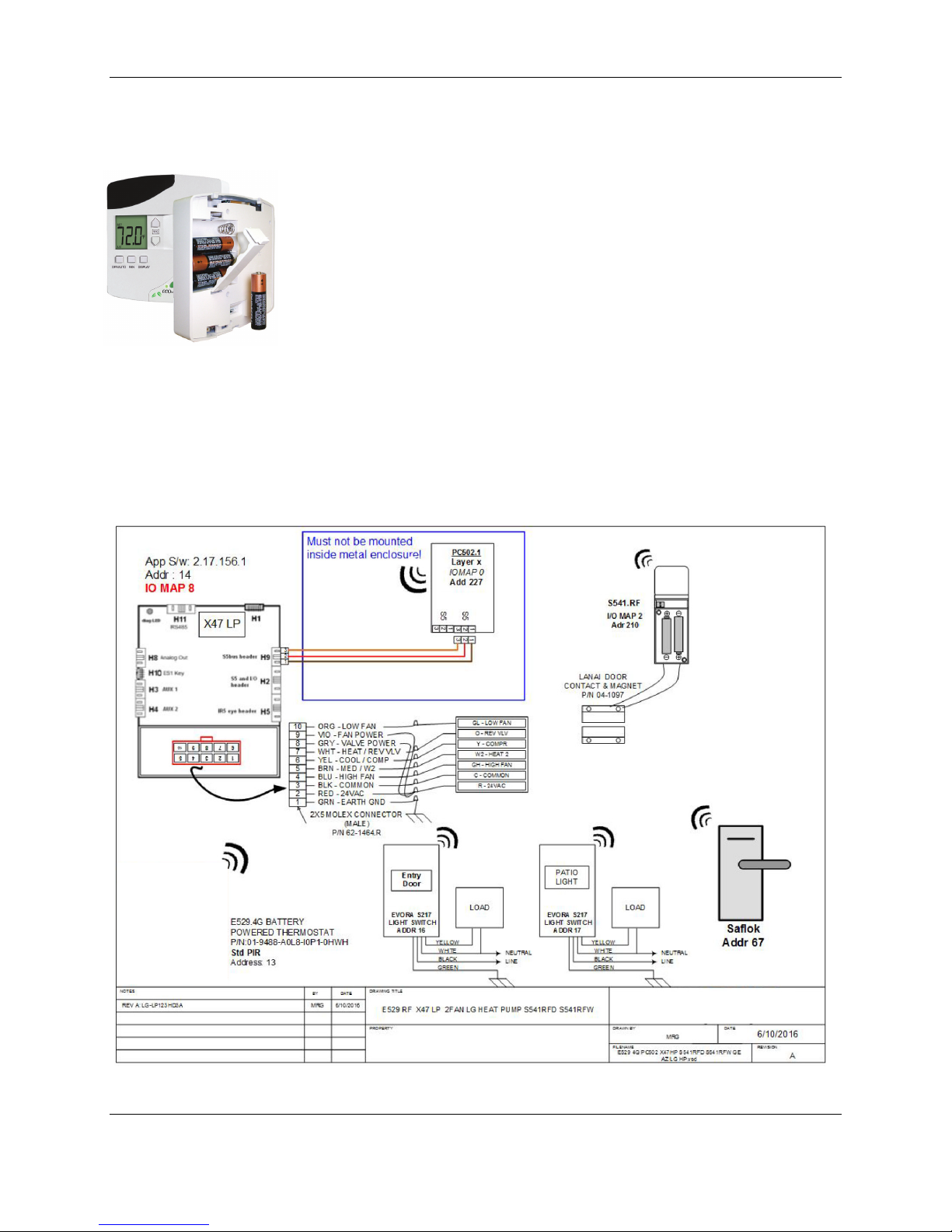
Figure 1. Typical E529.4G Installation E529.4G
Overview and
General Concepts
The E529.4G battery-operated wireless RF thermostat works in conjunction
with an HVAC controller partner such as an INNCOM X47 or X07.P to monitor
and maintain room temperature. The E529.4G has an onboard temperature
and optional humidity sensor to measure room temperature and humidity and
reports this information to the HVAC controller partner physically connected to
the room HVAC unit. The E529.4G has no onboard relays or HVAC control
logic to control the room HVAC unit. It can only measure temperature an
optionally humidity and report this to its HVAC controller partner.
The E529.4G has no IR Eye or S5-Bus installed and only communicates with
other devices via RF. The HVAC partner in the room must be equipped with a
Deep Mesh Layer-X radio, or S5 Bus connected to a radio equipped device
such as a PC502.4G. Appendix 4 shows typical installations using the
E529.4G. Figure 1 below shows a typical E529.4G installation.
Since the E529.4G has a user interface, it can also be used to configure inroom devices that do not have a user interface such as an X47, PC502.4G or
X07.P. The E529.4G is routinely used as a commissioning tool.
Rev 2.0 3/20/2017 2

E529 Product Guide
Application
In its most basic form, the battery powered e529 functions as a programmable
DDC thermostat, automatically adjusting fan speeds and valves to achieve set
temperature (Note: Guests can manually select heat or cool by pressing the
OFF/AUTO button and cycling through OFF, AUTO, HEAT and COOL). The
e528 is also an “intelligent” device capable of linking ancillary sensors and
serving as an information gateway. For example, coupled with a magnetic door
switch (wired or wireless), motion detectors, and other devices, the e528
becomes the brain of a highly effective Energy Management System (EMS)
application, communicating EMS information requirements to central servers. It
comes standard with five relays and can be equipped with a radio frequency
(RF) transceiver and Passive Infrared (PIR) motion detector.
The e529 interfaces with all common HVAC unit voltage configurations (24 volt
to 277 volt). The e529 can be installed in a wireless INNCOM guestroom
control system, which makes installation feasible and affordable in either new
construction or retrofit installations.
Through interfaces with other devices and sensors, the e529 supports the
following functions:
Remote HVAC control
• Guestroom HVAC diagnostics
• Remote room occupancy indication
• Automatic lighting control
• Remote mini-bar access reporting
• Remote smoke detector annunciation
• Central Electronic Lock control
• Humidity control
• Remote drape control
• Outside temperature display
• Peak demand load shedding
• Property/Building Management System (PMS/BMS) interface
Rev 2.0 3/20/2017 3
 Loading...