

Page 1

GasBook
Honeywell Gas Detection
Page 2

1
Introduction
The Gas Book is intended to offer
a simple guide to
anyone considering the
use of xed and portable
gas detection equipment.
The aim has been to provide a complete
and comprehensive introduction to the
subject– from detailing the principles of
detection that different devices employ to
providing information on certications
and application suitability.
A diverse variety of applications
and processes increasingly involve
the use and manufacture of highly
dangerous substances, particularly
ammable, toxic and Oxygen gases.
Inevitably, occasional escapes of
gas occur, which create a potential
hazard to the industrial plants, their
employees and people living nearby.
Worldwide incidents, involving
asphyxiation, explosions and loss of
life, are a constant reminder of this
problem.
2
www.honeywellanalytics.com / www.gasmonitors.com2 www.honeywellanalytics.com
www.honeywellanalytics.com / www.gasmonitors.com
n most industries, one of the key parts of any safety plan for reducing
risks to personnel and plant is the use of early warning devices such
as gas detectors. These can help to provide more time in which to take
I
remedial or protective action. They can also be used as part of a total,
integrated monitoring and safety system which may include various other
safety aspects including fire detection and emergency process shutdown.
Gas detection can be divided into two overriding categories; fixed gas
detection and portable gas detection. As the name might suggest, fixed gas
detection represents a static type of detection system for flammable, toxic
and Oxygen gas hazards and is designed to monitor processes, and protect
plant and assets as well as personnel on-site.
Portable gas detection is designed specifically to protect personnel from
the threat of flammable, toxic or Oxygen gas hazards and is typically a
small device worn by an operator to monitor the breathing zone. Many sites
incorporate a mix of both fixed and portable gas detection as part of their
safety philosophy, but the suitability of which type to use will depend on
several factors, including how often the area is accessed by personnel.
Page 3

Contents
Section Subject Page Section Subject Page
1 Introduction 2
2 Honeywell Gas Detection brands 4-5
3 What is gas? 6
4 Gas hazards 7
5 Flammable gas hazards 8
Flammable limit 9
Flammable gas properties 10-11
Flammable gases data 12-19
6 Toxic gas hazards 20
Workplace exposure limits 21
Toxic exposure limits 22-25
Toxic gases data 26-29
7 Asphyxiant (Oxygen deciency) hazard 30
8 Oxygen enrichment 31
9 Typical areas that require gas detection 32-35
10 Principles of detection 36
Combustible gas sensor 36
Catalytic sensor 36
Speed of response 37
Sensor output 37
Calibration 38
Infrared gas detector 39
Open path ammable infrared gas detector 40
Electrochemical cell sensors 41
Photo Ionised Detection (PID) 42
Chemcassette
Comparison of gas detection techniques 43
11 Selecting gas detection 44-45
12 Maximising time and efciency 46-47
13 Communications protocols 48-49
14 Fixed gas detection from Honeywell 50-51
15 Portable gas detectors 52
Why are portable gas detectors so important? 54
Breathing zone 55
Typical gases requiring portable detection 55
Portable gas detector types 56
Operational modes of a gas detector 56
Features and functionality 57
Accessories 58
Alarms and status indication 59
Typical applications for portable gas detectors 60
Conned spaces 60-61
Marine 62
Water treatment industry 63
Military 64-65
Hazardous Material (HAZMAT)
emergency response 66
Oil and gas (on and offshore) 67
PID Information 68
Measuring Solvent, Fuel and VOC Vapour
in the workplace environment 68-71
Maintaining portable gas detection 72
Reducing the cost of device testing 73
How to perform a manual bump test 73
Portable gas detectors from Honeywell 74-75
16 North American hazardous area standards
and approvals 76
North American Ex marking and
area classication 77
17 European hazardous area standards
and approvals 78-79
®
sensor 42
18 ATEX 80-81
19 Area classication 86-87
20 Apparatus design 88-89
21 Apparatus classication 90-91
22 Ingress protection of enclosures 92-93
23 Safety integrity levels (SIL) 94-95
24 Gas detection systems 96-97
Location of sensors 98-99
Typical sensor mounting options 100
Typical system congurations 100-101
25 Installation 102
26 Gas detection maintenance and ongoing care 106-109
27 Glossary 110-113
IEC Standards 82-83
Equipment markings 84-85
3
Page 4
2
Honeywell Gas
Detection brands
At Honeywell Analytics our key focus is our customers. We believe that the evolution
of gas detection should be driven by the people using our equipment, rather than
engineers deciding the needs of industry. With this in mind, we listen to what our
customers want, rene our solutions to meet changing demands and we grow as our
customers grow to ensure we are able to provide an added value service that meets
individual requirements.
Working with Industry…
since the birth of gas detection
ith 50 years experience in the industry, we have been
inuential in gas detection since the very beginning.
Many of our historic products set new benchmarks
W
use and innovation. Today, our product lines have evolved to meet
the requirements of diverse industries and applications, delivering
comprehensive solutions designed to drive down the cost of gas
detection, whilst providing enhanced safety.
for gas detection in terms of performance, ease of
Our Technical Support Centre and Product Application and Training
Specialists, eld engineers and in-house engineering support represent
some of the very best the industry has to offer, providing over 1,100
years cumulative expertise, allowing us to deliver local business
support on a corporate scale.
4 www.honeywellanalytics.com / www.gasmonitors.com
Page 5

GAS
FACT
The word gas was
coined in 1650–60 by
J. B. van Helmont
(1577–1644), a Flemish
chemist. It comes from
the Greek word
for chaos.
W Technologies by Honeywell is a World leader in the gas
detection industry with a strong commitment to providing
customers with high performance, dependable portable
B
service and ongoing support.
We design, manufacture and market innovative portable gas detection
solutions for a wide variety of applications and industries, with options
to suit all budgets and hazard monitoring requirements.
Our comprehensive range includes options from single gas units that
require no ongoing maintenance, to feature-rich multi-gas devices that
deliver additional value-added functionality.
As a leading expert in the eld of portable gas detection, we provide
customised on-site/eld based training to meet specic customer
needs and application support to assist customers with the selection
and integration of solutions that are entirely t for purpose.
When it comes to device care, we also offer cost-effective benchmark
support and maintenance through our comprehensive approved
partner network.
products that are backed up by exceptional customer
Delivering value added solutions at
affordable prices for 25 years
BW Technologies by Honeywell was originally established in 1987
in Calgary, Canada. Over the last 25 years, we have been bringing
innovative gas detection solutions to market that add value, enhance
safety and help to reduce the ongoing cost of portable gas detection.
With ofces all over the World, and a diverse and talented team of
industry experts on hand to provide support to customers, we offer a
large corporate infrastructure supported by locally focused teams that
have a unique understanding of industry and applications as well as
regional needs.
5
Page 6
3
What is
Gas?
The name gas comes from the word
chaos. Gas is a swarm of molecules
moving randomly and chaotically,
constantly colliding with each other
and anything else around them. Gases
ll any available volume and due to the
very high speed at which they move will
mix rapidly into any atmosphere
in which they are released.
Vehicle engines
combust fuel
and Oxygen and
produce exhaust
gases that
include Nitrogen
Oxides, Carbon
Monoxide and
Carbon Dioxide.
Different gases are all around
us in everyday life. The air we
breathe is made up of several
different gases including
Oxygen and Nitrogen.
Air Composition
The table
gives the
sea-level
composition
of air (in
percent by
volume at the
temperature of
15°C and the
pressure of
101325 Pa).
Name Symbol Percent by Volume
Nitrogen N2 78.084%
Oxygen O
Argon Ar 0.934%
Carbon Dioxide CO
Neon Ne 0.001818%
Methane CH
2 20.9476%
2 0.0314%
4 0.0002%
Helium He 0.000524%
Krypton Kr 0.000114%
Hydrogen H
Xenon Xe 0.0000087%
6 www.honeywellanalytics.com / www.gasmonitors.com
2 0.00005%
Page 7
4
Gas
Hazards
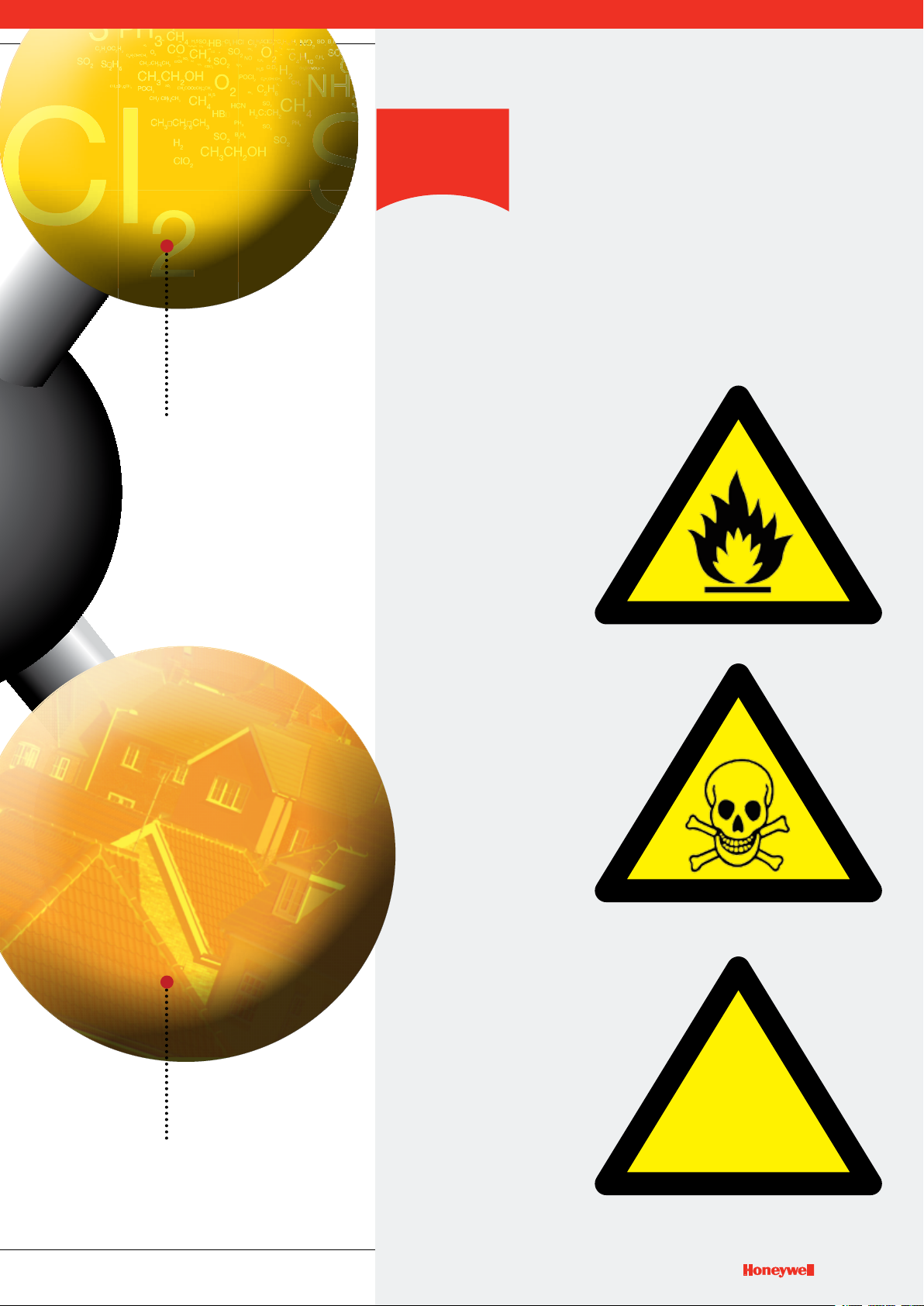
There are three main
types of gas hazard:
Gases can be lighter,
heavier or about the same
density as air. Gases
can have an odour or
be odourless. Gases
can have colour or be
colourless. If you can’t
see it, smell it or touch it,
it doesn’t mean that it is
not there.
Flammable
RISK OF FIRE
AND/OR EXPLOSION
e.g.
Methane,
Butane, Propane
Toxic
RISK OF
POISONING
e.g.
Carbon Monoxide,
Hydrogen, Chlorine
Natural Gas (Methane) is used
in many homes for heating
and cooking.
Asphyxiant
RISK OF
SUFFOCATION
e.g.
Oxygen deciency. Oxygen
can be consumed or
displaced by another gas
!
7
7
Page 8
5
Flammable
Gas Hazards
Combustion is a fairly simple
chemical reaction in which
Oxygen is combined rapidly
with another substance
resulting in the release of
energy. This energy appears
mainly as heat – sometimes
in the form of ames.
The igniting substance is
normally, but not always, a
Hydrocarbon compound and
can be solid, liquid, vapour
or gas. However, only gases
and vapours are considered
in this publication.
(N.B. The terms
‘ammable’, ‘explosive’,
and ‘combustible’
are, for the purpose
of this publication,
interchangeable).
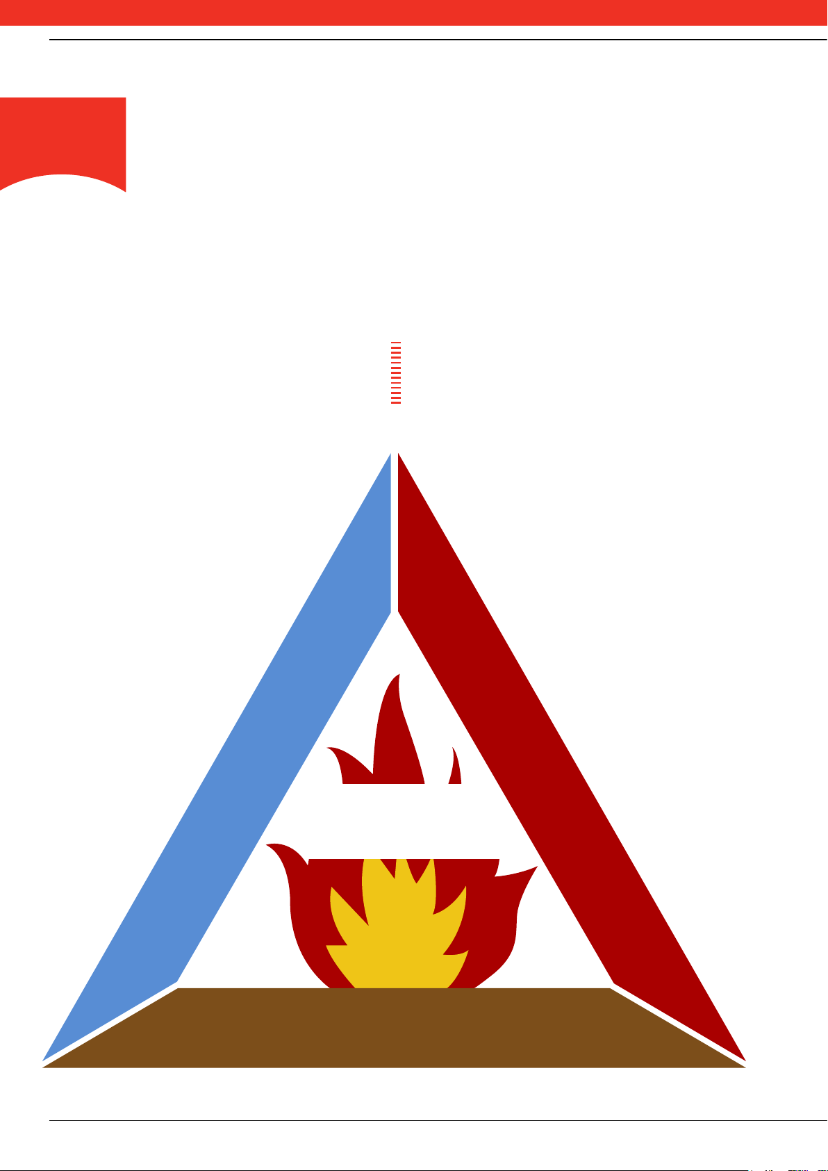
The Fire
Triangle
The process of combustion can be
represented by the well known re triangle.
Three factors are always needed to cause
combustion:
A SOURCE OF
IGNITION
1
OXYGEN
2
FUEL IN THE FORM
3
OF A GAS
OR VAPOUR
In any re protection system,
therefore, the aim is to always
remove at least one of these three
potentially hazardous items.
AIR
FIRE
FUEL
HEAT
8 www.honeywellanalytics.com / www.gasmonitors.com
Page 9
Flammable Limit
There is only a limited band of gas/air concentration which
will produce a combustible mixture. This band is specic
for each gas and vapour and is bounded by an upper level,
known as the Upper Explosive Limit (or the UEL) and a
lower level, called the Lower Explosive Limit (LEL).
Limits of Flammability
TOO RICH
GAS
FACT
High levels of O2 increase
the ammability of materials
and gases – at levels such
as 24%, items such as
clothing can spontaneously
combust!
100% v/v gas
0% v/v air
t levels below the LEL, there is
insufcient gas to produce an
explosion i.e. the mixture is too
A
the mixture has insufcient Oxygen i.e. the
mixture is too ‘rich’. The ammable range
therefore falls between the limits of the LEL
and UEL for each individual gas or mixture of
gases. Outside these limits, the mixture is not
capable of combustion. The Flammable Gases
Data on page 12 indicates the limiting values
for some of the better-known combustible
gases and compounds. The data is given for
gases and vapours at normal conditions of
pressure and temperature.
‘lean’, whilst above the UEL,
FLAMMABLE
RANGE
TOO LEAN
An increase in pressure, temperature or
Oxygen content will generally broaden the
ammability range.
In the average industrial plant, there would
normally be no gases leaking into the
surrounding area or, at worst, only a low
background level of gas present. Therefore the
detecting and early warning system will only
be required to detect levels from 0% of
gas up to the lower explosive limit. By the
time this concentration is reached,
shut-down procedures or site clearance
should have been put into operation. In fact
this will typically take place at a concentration
UEL
(upper explosive limit)
LEL
(lower explosive limit)
0% v/v gas
100% v/v air
of less than 50% of the LEL value, so that an
adequate safety margin is provided.
However, it should always be remembered
that in enclosed or unventilated areas, a
concentration in excess of the UEL can
sometimes occur. At times of inspection,
special care needs to be taken when operating
hatches or doors, since the ingress of air from
outside can dilute the gases to a hazardous,
combustible mixture.
(N.B LEL/LFL and UEL/UFL are, for the purpose of this
publication, interchangeable).
9
Page 10
Flammable Gas
Properties
Ignition Temperature
Flammable gases also have a temperature where ignition
will take place, even without an external ignition source
such as a spark or ame. This temperature is called the
Ignition Temperature. Apparatus for use in a hazardous
area must not have a surface temperature that exceeds the
Ignition Temperature. Apparatus is therefore marked with a
maximum surface temperature or T rating.
FLASH POINT (F.P. °C)
The ash point of a ammable liquid is the lowest temperature at which the surface of the
liquid emits sufcient vapour to be ignited by a small ame. Do not confuse this with Ignition
Temperature as the two can be very different:
Gas / Vapour Flash Point °C Ignition Temp. °C
Methane <-188 595
Kerosene 38 210
Bitumen 270 310
To convert a Celsius temperature into Fahrenheit: Tf = ((9/5)*Tc)+32 E.g. to convert -20 Celsius into Fahrenheit, first multiply the Celsius
temperature reading by nine-fifths to get -36. Then add 32 to get -4°F.
VAPOUR DENSITY
Helps determine sensor placement
The density of a gas/vapour is compared with air
When air = 1.0:
Vapour density < 1.0 will rise
Vapour density > 1.0 will fall
Gas/Vapour Vapour Density
Methane 0.55
Carbon Monoxide 0.97
Hydrogen Sulphide 1.45
Petrol Vapour 3.0 approx
10 www.honeywellanalytics.com / www.gasmonitors.com
Page 11

GAS
FACT
It’s not just gas that holds
a potential threat - dust
can also be explosive!
Examples of explosive
dusts include polystyrene,
cornstarch and iron.
11
11
Page 12

Flammable Gases Data
Molecular
WeightFormulaCAS NumberCommon Name
Acetaldehyde 75-07-0 CH3CHO 44.05 20 1.52 –38 4.00 60.00 74 1,108 204
Acetic acid 64-19-7 CH3COOH 60.05 118 2.07 40 4.00 17.00 100 428 464
Acetic anhydride 108-24-7 (CH3CO)2O 102.09 140 3.52 49 2.00 10.30 85 428 334
Acetone 67-64-1 (CH3)2CO 58.08 56 2.00 <–20 2.50 13.00 80 316 535
Acetonitrile 75-05-8 CH3CN 41.05 82 1.42 2 3.00 16.00 51 275 523
Acetyl chloride 75-36-5 CH3COCl 78.5 51 2.70 –4 5.00 19.00 157 620 390
Acetylene 74-86-2 CH=CH 26 -84 0.90 gas 2.30 100.00 24 1,092 305
Acetyl fluoride 557-99-3 CH3COF 62.04 20 2.14 <–17 5.60 19.90 142 505 434
Acrylaldehyde 107-02-8 CH2=CHCHO 56.06 53 1.93 –18 2.80 31.80 65 728 217
Acrylic acid 79-10-7 CH2=CHCOOH 72.06 139 2.48 56 2.90 85 406
Acrylonitrile 107-13-1 CH2=CHCN 53.1 77 1.83 –5 2.80 28.00 64 620 480
Acryloyl chloride 814-68-6 CH2CHCOCl 90.51 72 3.12 –8 2.68 18.00 220 662 463
Allyl acetate 591-87-7 CH2=CHCH2OOCCH3 100.12 103 3.45 13 1.70 10.10 69 420 348
Allyl alcohol 107-18-6 CH2=CHCH2CH 58.08 96 2.00 21 2.50 18.00 61 438 378
Allyl chloride 107-05-1 CH2=CHCH2Cl 76.52 45 2.64 –32 2.90 11.20 92 357 390
Ammonia 7664-41-7 NH3 17 -33 0.59 gas 15.00 33.60 107 240 630
Aniline 62-53-3 C6H6NH2 93.1 184 3.22 75 1.20 11.00 47 425 630
Benzaldehyde 100-52-7 C6H5CHO 106.12 179 3.66 64 1.40 62 192
Benzene 71-43-2 C6H6 78.1 80 2.70 –11 1.20 8.60 39 280 560
1-Bromobutane 109-65-9 CH3(CH2)2CH2Br 137.02 102 4.72 13 2.50 6.60 143 380 265
Bromoethane 74-96-4 CH3CH2Br 108.97 38 3.75 <–20 6.70 11.30 306 517 511
1,3 Butadiene 106-99-0 CH2=CHCH=CH2 54.09 -4.5 1.87 gas 1.40 16.30 31 365 430
Butane 106-97-8 C4H10 58.1 -1 2.05 gas 1.40 9.30 33 225 372
Isobutane 75-28-5 (CH3)2CHCH3 58.12 -12 2.00 gas 1.30 9.80 31 236 460
Butan-1-ol 71-36-3 CH3(CH2)2CH2OH 74.12 116 2.55 29 1.40 12.00 52 372 359
Butanone 78-93-3 CH3CH2COCH3 72.1 80 2.48 –9 1.50 13.40 45 402 404
But-1-ene 106-98-9 CH2=CHCH2CH3 56.11 -6.3 1.95 gas 1.40 10.00 38 235 440
But-2-ene (isomer not stated) 107-01-7 CH3CH=CHCH3 56.11 1 1.94 gas 1.60 10.00 40 228 325
Butyl acetate 123-86-4 CH3COOCH2(CH2)2CH3 116.2 127 4.01 22 1.20 8.50 58 408 370
n-Butyl acrylate 141-32-2 CH2=CHCOOC4H9 128.17 145 4.41 38 1.20 9.90 63 425 268
Butylamine 109-73-9 CH3(CH2)3NH2 73.14 78 2.52 –12 1.70 9.80 49 286 312
Isobutylamine 78-81-9 (CH3)2CHCH2NH2 73.14 64 2.52 –20 1.47 10.80 44 330 374
Isobutylisobutyrate 97-85-8 (CH3)2CHCOOCH2CH(CH3)2 144.21 145 4.93 34 0.80 47 424
Butylmethacrylate 97-88-1 CH2=C(CH3)COO(CH2)3CH3 142.2 160 4.90 53 1.00 6.80 58 395 289
Tert-butyl methyl ether 1634-04-4 CH3OC(CH3)2 88.15 55 3.03 –27 1.50 8.40 54 310 385
n-Butylpropionate 590-01-2 C2H5COOC4H9 130.18 145 4.48 40 1.00 7.70 53 409 389
Butyraldehyde 123-72-8 CH3CH2CH2CHO 72.1 75 2.48 –16 1.80 12.50 54 378 191
Isobutyraldehyde 78-84-2 (CH3)2CHCHO 72.11 63 2.48 –22 1.60 11.00 47 320 176
Carbon disulphide 75-15-0 CS2 76.1 46 2.64 –30 0.60 60.00 19 1,900 95
Carbon monoxide 630-08-0 CO 28 -191 0.97 gas 10.90 74.00 126 870 805
Carbonyl sulphide 463-58-1 COS 60.08 -50 2.07 gas 6.50 28.50 100 700 209
Chlorobenzene 108-90-7 C6H5Cl 112.6 132 3.88 28 1.30 11.00 60 520 637
1-Chlorobutane 109-69-3 CH3(CH2)2CH2Cl 92.57 78 3.20 –12 1.80 10.00 69 386 250
2-Chlorobutane 78-86-4 CH3CHClC2H5 92.57 68 3.19 <–18 2.00 8.80 77 339 368
1-Chloro-2,3-epoxypropane 106-89-8 OCH2CHCH2Cl 92.52 115 3.30 28 2.30 34.40 86 1,325 385
Chloroethane 75-00-3 CH3CH2Cl 64.5 12 2.22 gas 3.60 15.40 95 413 510
2-Chloroethanol 107-07-3 CH2ClCH2OH 80.51 129 2.78 55 4.90 16.00 160 540 425
Chloroethylene 75-01-4 CH2=CHCl 62.3 -15 2.15 gas 3.60 33.00 94 610 415
Chloromethane 74-87-3 CH3Cl 50.5 -24 1.78 gas 7.60 19.00 160 410 625
1-Chloro-2-methylpropane 513-36-0 (CH3)2CHCH2Cl 92.57 68 3.19 <–14 2.00 8.80 75 340 416
3-Chloro-2-methylprop-1-ene 563-47-3 CH2=C(CH3)CH2Cl 90.55 71 3.12 –16 2.10 77 478
5-Chloropentan-2-one 5891-21-4 CH3CO(CH2)3Cl 120.58 71 4.16 61 2.00 98 440
1-Chloropropane 540-54-5 CH3CH2CH2Cl 78.54 37 2.70 –32 2.40 11.10 78 365 520
2-Chloropropane 75-29-6 (CH3)2CHCl 78.54 47 2.70 <–20 2.80 10.70 92 350 590
Chlorotrifluoroethyl-ene 79-38-9 CF2=CFCl 116.47 -28.4 4.01 gas 4.60 84.30 220 3,117 607
-Chlorotoluene 100-44-7 C6H5CH2Cl 126.58 4.36 60 1.10 55 585
Boiling
Point °C
Relative
Vapourisation Density
12 www.honeywellanalytics.com / www.gasmonitors.com
12
www.honeywellanalytics.com / www.gasmonitors.com
Page 13
References: BS EN 60079-20-1 (supersedes 61779) Electrical apparatus for the detection and
measurement of flammable gases-Part 1: General requirements and test methods. NIST Chemistry Web
Book June 2005 release. Aldrich Handbook of Fine Chemicals and Laboratory Equipment 2003-2004.
Data may change by country
and date, always refer to local
up-to-date regulations.
Please note: Where “gas” is stated under Flash Point (F.P. C°), the compound is always in a gaseous state
and therefore does not have a FP.
Flammable Limits
F.P. °C LFL % v/v UFL % v/v LFL mg/L UFL mg/L I.T. °C
13
13
Page 14

Flammable Gases Data (continued)
Molecular
WeightFormulaCAS NumberCommon Name
Cresols (mixed isomers) 1319-77-3 CH3C5H4OH 108.14 191 3.73 81 1.10 50 555
Crotonaldehyde 123-73-9 CH3CH=CHCHO 70.09 102 2.41 13 2.10 16.00 82 470 280
Cumene 98-82-8 C6H5CH(CH3)2 120.19 152 4.13 31 0.80 6.50 40 328 424
Cyclobutane 287-23-0 CH2(CH2)2CH2 56.1 13 1.93 gas 1.80 42
Cycloheptane 291-64-5 CH2(CH2)5CH2 98.19 118.5 3.39 <10 1.10 6.70 44 275
Cyclohexane 110-82-7 CH2(CH2)4CH2 84.2 81 2.90 –18 1.00 8.00 35 290 259
Cyclohexanol 108-93-0 CH2(CH2)4CHOH 100.16 161 3.45 61 1.20 11.10 50 460 300
Cyclohexanone 108-94-1 CH2(CH2)4CO 98.1 156 3.38 43 1.30 8.40 53 386 419
Cyclohexene 110-83-8 CH2(CH2)3CH=CH 82.14 83 2.83 –17 1.10 8.30 37 244
Cyclohexylamine 108-91-8 CH2(CH2)4CHNH2 99.17 134 3.42 32 1.10 9.40 47 372 293
Cyclopentane 287-92-3 CH2(CH2)3CH2 70.13 50 2.40 –37 1.40 41 320
Cyclopentene 142-29-0 CH=CHCH2CH2CH 68.12 44 2.30 <–22 1.48 41 309
Cyclopropane 75-19-4 CH2CH2CH2 42.1 -33 1.45 gas 2.40 10.40 42 183 498
Cyclopropyl methyl ketone 765-43-5 CH3COCHCH2CH2 84.12 114 2.90 15 1.70 58 452
p-Cymene 99-87-6 CH3CH6H4CH(CH3)2 134.22 176 4.62 47 0.70 5.60 39 366 436
Decahydro-naphthalene trans 493-02-7 CH2(CH2)3CHCH(CH2)3CH2 138.25 185 4.76 54 0.70 4.90 40 284 288
Decane (mixed isomers) 124-18-5 C10H22 142.28 173 4.90 46 0.70 5.60 41 332 201
Dibutyl ether 142-96-1 (CH3(CH2)3)2O 130.2 141 4.48 25 0.90 8.50 48 460 198
Dichlorobenzenes (isomer not stated)
Dichlorodiethyl-silane 1719-53-5 (C2H5)SiCl2 157.11 128 24 3.40 223
1,1-Dichloroethane 75-34-3 CH3CHCl2 99 57 3.42 –10 5.60 16.00 230 660 440
1,2-Dichloroethane 107-06-2 CH2ClCH2Cl 99 84 3.42 13 6.20 16.00 255 654 438
Dichloroethylene 540-59-0 ClCH=CHCl 96.94 37 3.55 –10 9.70 12.80 391 516 440
1,2-Dichloro-propane 78-87-5 CH3CHClCH2Cl 113 96 3.90 15 3.40 14.50 160 682 557
Dicyclopentadiene 77-73-6 C10H12 132.2 170 4.55 36 0.80 43 455
Diethylamine 109-89-7 (C2H5)2NH 73.14 55 2.53 –23 1.70 10.00 50 306 312
Diethylcarbonate 105-58-8 (CH3CH2O)2CO 118.13 126 4.07 24 1.40 11.70 69 570 450
Diethyl ether 60-29-7 (CH3CH5)2O 74.1 34 2.55 –45 1.70 36.00 60 1,118 160
1,1-Difluoro-ethylene 75-38-7 CH2=CF2 64.03 -83 2.21 gas 3.90 25.10 102 665 380
Diisobutylamine 110-96-3 ((CH3)2CHCH2)2NH 129.24 137 4.45 26 0.80 3.60 42 190 256
Diisobutyl carbinol 108-82-7 ((CH3)2CHCH2)2CHOH 144.25 178 4.97 75 0.70 6.10 42 370 290
Diisopentyl ether 544-01-4 (CH3)2CH(CH2)2O(CH2)2CH(CH3)2 158.28 170 5.45 44 1.27 104 185
Diisopropylamine 108-18-9 ((CH3)2CH)2NH 101.19 84 3.48 –20 1.20 8.50 49 358 285
Diisopropyl ether 108-20-3 ((CH3)2CH)2O 102.17 69 3.52 –28 1.00 21.00 45 900 405
Dimethylamine 124-40-3 (CH3)2NH 45.08 7 1.55 gas 2.80 14.40 53 272 400
Dimethoxymethane 109-87-5 CH2(OCH)3)2 76.09 41 2.60 –21 2.20 19.90 71 630 247
3-(Dimethylamino)propiononitrile 1738-25-6 (CH3)2NHCH2CH2CN 98.15 171 3.38 50 1.57 62 317
Dimethyl ether 115-10-6 (CH3)2O 46.1 -25 1.59 gas 2.70 32.00 51 610 240
N,N-Dimethylformamide 68-12-2 HCON(CH3)2 73.1 152 2.51 58 1.80 16.00 55 500 440
3,4-Dimethyl hexane 583-48-2 CH3CH2CH(CH3)CH(CH3)CH2CH3 114.23 119 3.87 2 0.80 6.50 38 310 305
N,N-Dimethyl hydrazine 57-14-7 (CH3)2NNH2 60.1 62 2.07 –18 2.40 20 60 490 240
1,4-Dioxane 123-91-1 OCH2CH2OCH2CH2 88.1 101 3.03 11 1.40 22.50 51 813 379
1,3-Dioxolane 646-06-0 OCH2CH2OCH2 74.08 74 2.55 –5 2.30 30.50 70 935 245
Dipropylamine 142-84-7 (CH3CH2CH2)2NH 101.19 105 3.48 4 1.20 9.10 50 376 280
Ethane 74-84-0 CH3CH3 30.1 -87 1.04 gas 2.50 15.50 31 194 515
Ethanethiol 75-08-1 CH3CH2SH 62.1 35 2.11 <–20 2.80 18.00 73 466 295
Ethanol 64-17-5 CH3CH2OH 46.1 78 1.59 12 3.10 19.00 59 359 363
2-Ethoxyethanol 110-80-5 CH3CH2OCH2CH2OH 90.12 135 3.10 40 1.70 15.70 68 593 235
2-Ethoxyethyl acetate 111-15-9 CH3COOCH2CH2OCH2CH3 132.16 156 4.72 47 1.20 12.70 65 642 380
Ethyl acetate 141-78-6 CH3COOCH2CH3 88.1 77 3.04 –4 2.00 2.80 73 470 460
Ethyl acetoacetate 141-97-9 CH3COCH2COOCH2CH3 130.14 181 4.50 65 1.00 9.50 54 519 350
Ethyl acrylate 140-88-5 CH2=CHCOOCH2CH3 100.1 100 3.45 9 1.40 14.00 59 588 350
Ethylamine 75-04-7 C2H5NH2 45.08 16.6 1.50 <–20 3.50 14.00 49 260 425
Ethylbenzene 100-41-4 CH2CH3C6H5 106.2 135 3.66 23 0.80 7.80 44 340 431
Ethyl butyrate 105-54-4 CH3CH2CH2COOC2H5 116.16 120 4.00 21 1.40 66 435
Ethylcyclobutane 4806-61-5 CH3CH2CHCH2CH2CH2 84.16 2.90 <–16 1.20 7.70 42 272 212
Ethylcyclohexane 1678-91-7 CH3CH2CH(CH2)4CH2 112.2 131 3.87 <24 0.80 6.60 42 310 238
Ethylcyclopentane 1640-89-7 CH3CH2CH(CH2)3CH2 98.2 103 3.40 <5 1.05 6.80 42 280 262
Ethylene 74-85-1 CH2=CH2 28.1 -104 0.97 2.30 36.00 26 423 425
106-46-7 C6H4Cl2 147 179 5.07 86 2.20 9.20 134 564 648
Boiling
Point °C
Relative
Vapourisation Density
14 www.honeywellanalytics.com / www.gasmonitors.com
14
www.honeywellanalytics.com / www.gasmonitors.com
Page 15
Flammable Limits
F.P. °C LFL % v/v UFL % v/v LFL mg/L UFL mg/L I.T. °C
15
15
Page 16

Flammable Gases Data (continued)
Molecular
WeightFormulaCAS NumberCommon Name
Ethylenediamine 107-15-3 NH2CH2CH2NH2 60.1 118 2.07 34 2.50 18.00 64 396 403
Ethylene oxide 75-21-8 CH2CH2O 44 11 1.52 <–18 2.60 100.00 47 1,848 435
Ethyl formate 109-94-4 HCOOCH2CH3 74.08 52 2.65 –20 2.70 16.50 87 497 440
Ethyl isobutyrate 97-62-1 (CH3)2CHCOOC2H5 116.16 112 4.00 10 1.60 75 438
Ethyl methacrylate 97-63-2 CH2=CCH3COOCH2CH3 114.14 118 3.90 20 1.50 70
Ethyl methyl ether 540-67-0 CH3OCH2CH3 60.1 8 2.10 gas 2.00 10.10 50 255 190
Ethyl nitrite 109-95-5 CH3CH2ONO 75.07 2.60 –35 3.00 50.00 94 1,555 95
Formaldehyde 50-00-0 HCHO 30 -19 1.03 60 7.00 73.00 88 920 424
Formic acid 64-18-6 HCOOH 46.03 101 1.60 42 18.00 57.00 190 1,049 520
2-Furaldehyde 98-01-1 OCH=CHCH=CHCHO 96.08 162 3.30 60 2.10 19.30 85 768 316
Furan 110-00-9 CH=CHCH=CHO 68.07 32 2.30 <–20 2.30 14.30 66 408 390
Furfuryl alcohol 98-00-0 OC(CH2OH)CHCHCH 98.1 170 3.38 61 1.80 16.30 70 670 370
1,2,3-Trimethyl-benzene 526-73-8 CHCHCHC(CH3)C(CH3)C(CH3) 120.19 175 4.15 51 0.80 7.00 470
Heptane (mixed isomers) 142-82-5 C7H16 100.2 98 3.46 –4 0.85 6.70 35 281 215
Hexane (mixed isomers) 110-54-3 CH3(CH2)4CH3 86.2 69 2.97 –21 1.00 8.90 35 319 233
1-Hexanol 111-27-3 C6H13OH 102.17 156 3.50 63 1.10 47 293
Hexan-2-one 591-78-6 CH3CO(CH2)3CH3 100.16 127 3.46 23 1.20 9.40 50 392 533
Hydrogen 1333-74-0 H2 2 -253 0.07 gas 4.00 77.00 3.4 63 560
Hydrogen cyanide 74-90-8 HCN 27 26 0.90 <–20 5.40 46.00 60 520 538
Hydrogen sulphide 7783-06-4 H2S 34.1 -60 1.19 gas 4.00 45.50 57 650 270
4-Hydroxy-4-methyl-penta-2-one 123-42-2 CH3COCH2C(CH3)2OH 116.16 166 4.00 58 1.80 6.90 88 336 680
Kerosene 8008-20-6 150 38 0.70 5.00 210
1,3,5-Trimethylbenzene 108-67-8 CHC(CH3)CHC(CH3)CHC(CH3) 120.19 163 4.15 44 0.80 7.30 40 365 499
Methacryloyl chloride 920-46-7 CH2CCH3COCl 104.53 95 3.60 17 2.50 106 510
Methane (firedamp) 74-82-8 CH4 16 -161 0.55 <–188 4.40 17.00 29 113 537
Methanol 67-56-1 CH3OH 32 65 1.11 11 6.00 36.00 73 665 386
Methanethiol 74-93-1 CH3SH 48.11 6 1.60 4.10 4.10 21.00 80 420
2-Methoxyethanol 109-86-4 CH3OCH2CH2OH 76.1 124 2.63 39 1.80 20.60 76 650 285
Methyl acetate 79-20-9 CH3COOCH3 74.1 57 2.56 –10 3.10 16.00 95 475 502
Methyl acetoacetate 105-45-3 CH3COOCH2COCH3 116.12 169 4.00 62 1.30 14.20 62 685 280
Methyl acrylate 96-33-3 CH2=CHCOOCH3 86.1 80 3.00 –3 1.95 16.30 71 581 415
Methylamine 74-89-5 CH3NH2 31.1 -6 1.00 gas 4.20 20.70 55 270 430
2-Methylbutane 78-78-4 (CH3)2CHCH2CH3 72.15 30 2.50 –56 1.30 8.30 38 242 420
2-Methylbutan-2-ol 75-85-4 CH3CH2C(OH)(CH3)2 88.15 102 3.03 16 1.40 10.20 50 374 392
3-Methylbutan-1-ol 123-51-3 (CH3)2CH(CH2)2OH 88.15 130 3.03 42 1.30 10.50 47 385 339
2-Methylbut-2-ene 513-35-9 (CH3)2C=CHCH3 70.13 35 2.40 –53 1.30 6.60 37 189 290
Methyl chloro-formate 79-22-1 CH3OOCC 94.5 70 3.30 10 7.50 26 293 1,020 475
Methylcyclohexane 108-87-2 CH3CH(CH2)4CH2 98.2 101 3.38 –4 1.00 6.70 41 275 258
Methylcyclo-pentadienes
Methylcyclopentane 96-37-7 CH3CH(CH2)3CH2 84.16 72 2.90 <–10 1.00 8.40 35 296 258
Methylenecyclo-butane 1120-56-5 C(=CH2)CH2CH2CH2 68.12 2.35 <0 1.25 8.60 35 239 352
2-Methyl-1-buten-3-yne 78-80-8 HC=CC(CH3)CH2 66.1 32 2.28 –54 1.40 38 272
Methyl formate 107-31-3 HCOOCH3 60.05 32 2.07 –20 5.00 23.00 125 580 450
2-Methylfuran 534-22-5 OC(CH3)CHCHCH 82.1 63 2.83 <–16 1.40 9.70 47 325 318
Methylisocyanate 624-83-9 CH3NCO 57.05 37 1.98 –7 5.30 26.00 123 605 517
Methyl methacrylate 80-62-6 CH3=CCH3COOCH3 100.12 100 3.45 10 1.70 12.50 71 520 430
4-Methylpentan-2-ol 108-11-2 (CH3)2CHCH2CHOHCH3 102.17 132 3.50 37 1.14 5.50 47 235 334
4-Methylpentan-2-one 108-10-1 (CH3)2CHCH2COCH3 100.16 117 3.45 16 1.20 8.00 50 336 475
2-Methylpent-2-enal 623-36-9 CH3CH2CHC(CH3)COH 98.14 137 3.78 30 1.46 58 206
4-Methylpent-3-en-2-one 141-79-7 (CH3)2(CCHCOCH)3 98.14 129 3.78 24 1.60 7.20 64 289 306
2-Methyl-1-propanol 78-83-1 (CH3)2CHCH2OH 74.12 108 2.55 28 1.40 11.00 43 340 408
2-Methylprop-1-ene 115-11-7 (CH3)2C=CH2 56.11 -6.9 1.93 gas 1.60 10 37 235 483
2-Methylpyridine 109-06-8 NCH(CH3)CHCHCHCH 93.13 128 3.21 27 1.20 45 533
3-Methylpyridine 108-99-6 NCHCH(CH3)CHCHCH 93.13 144 3.21 43 1.40 8.10 53 308 537
4-Methylpyridine 108-89-4 NCHCHCH(CH3)CHCH 93.13 145 3.21 43 1.10 7.80 42 296 534
-Methyl styrene 98-83-9 C6H5C(CH3)=CH2 118.18 165 4.08 40 0.80 11.00 44 330 445
Methyl tert-pentyl ether 994-05-8 (CH3)2C(OCH3)CH2CH3 102.17 85 3.50 <–14 1.50 62 345
2-Methylthiophene 554-14-3 SC(CH3)CHCHCH 98.17 113 3.40 –1 1.30 6.50 52 261 433
Morpholine 110-91-8 OCH2CH2NHCH2CH2 87.12 129 3.00 31 1.40 15.20 65 550 230
(isomer not stated)
26519-91-5 C6H6 80.13 2.76 <–18 1.30 7.60 43 249 432
Boiling
Point °C
Relative
Vapourisation Density
16 www.honeywellanalytics.com / www.gasmonitors.com
16
www.honeywellanalytics.com / www.gasmonitors.com
Page 17
Flammable Limits
F.P. °C LFL % v/v UFL % v/v LFL mg/L UFL mg/L I.T. °C
17
17
Page 18

Flammable Gases Data (continued)
Molecular
WeightFormulaCAS NumberCommon Name
Naphtha 35 2.50 <–18 0.90 6.00 290
Naphthalene 91-20-3 C10H8 128.17 218 4.42 77 0.60 5.90 29 317 528
Nitrobenzene 98-95-3 CH3CH2NO2 123.1 211 4.25 88 1.40 40.00 72 2,067 480
Nitroethane 79-24-3 C2H5NO2 75.07 114 2.58 27 3.40 107 410
Nitromethane 75-52-5 CH3NO2 61.04 102.2 2.11 36 7.30 63.00 187 1,613 415
1-Nitropropane 108-03-2 CH3CH2CH2NO2 89.09 131 3.10 36 2.20 82 420
Nonane 111-84-2 CH3(CH2)7CH2 128.3 151 4.43 30 0.70 5.60 37 301 205
Octane 111-65-9 CH3(CH2)3CH3 114.2 126 3.93 13 0.80 6.50 38 311 206
1-Octanol 111-87-5 CH3(CH2)6CH2OH 130.23 196 4.50 81 0.90 7.00 49 385 270
Penta-1,3-diene 504-60-9 CH2=CH-CH=CH-CH3 68.12 42 2.34 <–31 1.20 9.40 35 261 361
Pentanes (mixed isomers) 109-66-0 C5H12 72.2 36 2.48 –40 1.40 7.80 42 261 258
Pentane-2,4-dione 123-54-6 CH3COCH2COCH3 100.1 140 3.50 34 1.70 71 340
Pentan-1-ol 71-41-0 CH3(CH2)3CH2OH 88.15 136 3.03 38 1.06 10.50 36 385 298
Pentan-3-one 96-22-0 (CH3CH2)2CO 86.13 101.5 3.00 12 1.60 58 445
Pentyl acetate 628-63-7 CH3COO-(CH2)4-CH3 130.18 147 4.48 25 1.00 7.10 55 387 360
Petroleum 2.80 <–20 1.20 8.00 560
Phenol 108-95-2 C6H5OH 94.11 182 3.24 75 1.30 9.50 50 370 595
Propane 74-98-6 CH3CH2CH3 44.1 -42 1.56 gas 1.70 10.90 31 200 470
Propan-1-ol 71-23-8 CH3CH2CH2OH 60.1 97 2.07 22 2.10 17.50 52 353 405
Propan-2-ol 67-63-0 (CH3)2CHOH 60.1 83 2.07 12 2.00 12.70 50 320 425
Propene 115-07-1 CH2=CHCH3 42.1 -48 gas 2.00 11.10 35 194 455
Propionic acid 79-09-4 CH3CH2COOH 74.08 141 2.55 52 2.10 12.00 64 370 435
Propionic aldehyde 123-38-6 C2H5CHO 58.08 46 2.00 <–26 2.00 47 188
Propyl acetate 109-60-4 CH3COOCH2CH2CH3 102.13 102 3.60 10 1.70 8.00 70 343 430
Isopropyl acetate 108-21-4 CH3COOCH(CH3)2 102.13 85 3.51 4 1.70 8.10 75 340 467
Propylamine 107-10-8 CH3(CH2)2NH2 59.11 48 2.04 –37 2.00 10.40 49 258 318
Isopropylamine 75-31-0 (CH3)2CHNH2 59.11 33 2.03 <–24 2.30 8.60 55 208 340
Isopropyl Chloroacetate 105-48-6 ClCH2COOCH(CH3)2 136.58 149 4.71 42 1.60 89 426
2-Isopropyl-5-methylhex-2-enal 35158-25-9 (CH3)2CH-C(CHO)CHCH2CH(CH3)2 154.25 189 5.31 41 3.05 192 188
Isopropyl nitrate 1712-64-7 (CH3)2CHONO2 105.09 101 11 2.00 100.00 75 3,738 175
Propyne 74-99-7 CH3C=CH 40.06 -23.2 1.38 gas 1.70 16.8 28 280 340
Prop-2-yn-1-ol 107-19-7 HC=CCH2OH 56.06 114 1.89 33 2.40 55 346
Pyridine 110-86-1 C5H5N 79.1 115 2.73 17 1.70 12.40 56 398 550
Styrene 100-42-5 C6H5CH=CH2 104.2 145 3.60 30 1.00 8.00 42 350 490
Tetrafluoroethylene 116-14-3 CF2=CF2 100.02 3.40 gas 10.00 59.00 420 2,245 255
2,2,3,3-Tetrafluoropropyl acrylate 7383-71-3 CH2=CHCOOCH2CF2CF2H 186.1 132 6.41 45 2.40 182 357
2,2,3,3
-Tetrafluoropropyl methacrylate
Tetrahydrofuran 109-99-9 CH2(CH2)2CH2O 72.1 64 2.49 –20 1.50 12.40 46 370 224
Tetrahydrofurfuryl alcohol 97-99-4 OCH2CH2CH2CHCH2OH 102.13 178 3.52 70 1.50 9.70 64 416 280
Tetrahydrothiophene 110-01-0 CH2(CH2)2CH2S 88.17 119 3.04 13 1.00 12.30 42 450 200
N,N,N’, N’-Tetramethyldiaminomethane
Thiophene 110-02-1 CH=CHCH=CHS 84.14 84 2.90 –9 1.50 12.50 50 420 395
Toluene 108-88-3 C6H5CH3 92.1 111 3.20 4 1.10 7.80 39 300 535
Triethylamine 121-44-8 (CH3CH2)3N 101.2 89 3.50 –7 1.20 8.00 51 339
1,1,1-Trifluoroethane 420-46-2 CF3CH3 84.04 2.90 6.80 17.60 234 605 714
2,2,2-Trifluoroethanol 75-89-8 CF3CH2OH 100.04 77 3.45 30 8.40 28.80 350 1,195 463
Trifluoroethylene 359-11-5 CF2=CFH 82.02 2.83 27.00 502 904 319
3,3,3-Trifluoro-prop-1-ene 677-21-4 CF3CH=CH2 96.05 -16 3.31 4.70 184 490
Trimethylamine 75-50-3 (CH3)3N 59.1 3 2.04 gas 2.00 12.00 50 297 190
2,2,4-Trimethylpentane 540-84-1 (CH3)2CHCH2C(CH3)3 114.23 98 3.90 –12 0.70 6.00 34 284 411
2,4,6-Trimethyl-1,3,5-trioxane 123-63-7 OCH(CH3)OCH(CH3)OCH(CH3) 132.16 123 4.56 27 1.30 72 235
1,3,5-Trioxane 110-88-3 OCH2OCH2OCH2 90.1 115 3.11 45 3.20 29.00 121 1,096 410
Turpentine C10H16 149 35 0.80 254
Isovaleraldehyde 590-86-3 (CH3)2CHCH2CHO 86.13 90 2.97 –12 1.30 13.00 60 207
Vinyl acetate 108-05-4 CH3COOCH=CH2 86.09 72 3.00 –8 2.60 13.40 93 478 425
Vinylcyclohexenes (isomer not stated)
Vinylidene chloride 75-35-4 CH2=CCl2 96.94 30 3.40 –18 6.50 16.00 260 645 440
2-Vinylpyridine 100-69-6 NC(CH2=CH)CHCHCHCH 105.14 79 3.62 35 1.20 51 482
4-Vinylpyridine 100-43-6 NCHCHC(CH2=CH)CHCH 105.14 62 3.62 43 1.10 47 501
Xylenes 1330-20-7 C6H4(CH3)2 106.2 144 3.66 30 1.00 7.60 44 335 464
45102-52-1 CH2=C(CH2)COOCH2CF2CF2H 200.13 124 6.90 46 1.90 155 389
51-80-9 (CH3)2NCH2N(CH3)2 102.18 85 3.50 <–13 1.61 67 180
100-40-3 CH2CHC6H9 108.18 126 3.72 15 0.80 35 257
Boiling
Point °C
Relative
Vapourisation Density
18 www.honeywellanalytics.com / www.gasmonitors.com
18
www.honeywellanalytics.com / www.gasmonitors.com
Page 19
Flammable Limits
F.P. °C LFL % v/v UFL % v/v LFL mg/L UFL mg/L I.T. °C
19
19
Page 20

6
Toxic Gas
Hazards
Some gases are poisonous and can be dangerous to life at very low
concentrations. Some toxic gases have strong smells like the distinctive
‘rotten eggs’ smell of Hydrogen Sulphide (H
often used for the concentration of toxic gases are parts per million (ppm)
and parts per billion (ppb). For example 1ppm would be equivalent to a
room lled with a total of 1 million balls and 1 of those balls being red.
The red ball would represent 1ppm.
S). The measurements most
2
1 MILLION
BALLS
ore people die from toxic gas
exposure than from explosions
caused by the ignition of
M
noted that there is a large group of gases
which are both combustible and toxic, so
that even detectors of toxic gases
sometimes have to carry hazardous
area approval). The main reason for
ammable gas. (It should be
treating ammable and toxic gases separately
is that the hazards and regulations involved
and the types of sensor required are different.
With toxic substances, apart from the obvious
environmental problems, the main concern
is the effect on workers of
exposure to even very low
concentrations, which could be
inhaled, ingested, or absorbed
through the skin. Since adverse
effects can often result from
additive, long-term exposure,
it is important not only to
measure the concentration of
gas, but also the total time of
exposure. There are even some
known cases of synergism,
where substances
can interact and produce
a far worse effect when
combined than the separate
effect of each on its own.
Concern about concentrations of toxic
substances in the workplace focus on both
organic and inorganic compounds, including
the effects they could have on the health
and safety of employees, the possible
contamination of a manufactured end-product
(or equipment used in its manufacture) and
also the subsequent disruption of normal
working activities.
www.honeywellanalytics.com / www.gasmonitors.com20
www.honeywellanalytics.com / www.gasmonitors.com
Page 21

Workplace
Exposure
Limits
The term ‘workplace exposure limits’ or ‘occupational
hazard monitoring’ is generally used to cover the area of
industrial health monitoring associated with the exposure
of employees to hazardous conditions of gases, dust,
noise etc. In other words, the aim is to ensure that levels
in the workplace are below the statutory limits.
1 RED
BALL
100%V/V = 1,000,000ppm
1%V/V = 10,000ppm
EXAMPLE
100%LEL Ammonia = 15%V/V
50%LEL Ammonia = 7.5%V/V
50%LEL Ammonia = 75,000ppm
his subject covers both area
surveys (proling of potential
exposures) and personal
T
worn by a worker and sampling is carried out
as near to the breathing zone as possible.
This ensures that the measured level of
contamination is truly representative of that
inhaled by the worker.
It should be emphasised that both personal
monitoring and monitoring of the workplace
should be considered as important parts of an
overall, integrated safety plan. They are only
intended to provide the necessary information
about conditions as they exist in the
atmosphere. This then allows the necessary
monitoring, where instruments are
action to be taken to comply with
the relevant industrial regulations
and safety requirements.
Whatever method is decided upon, it is
important to take into account the nature of
the toxicity of any of the gases involved.
For instance, any instrument which
measures only a time-weighted average,
or an instrument which draws a sample for
subsequent laboratory analysis, would not
protect a worker against a short exposure to
a lethal dose of a highly toxic substance. On
the other hand, it may be quite normal to briey
exceed the average, Long-Term Exposure Limit
(LTEL) levels in some areas of a plant, and it
need not be indicated as an alarm situation.
Therefore, the optimum instrument system
should be capable of monitoring both short
and long-term exposure levels as well as
instantaneous alarm levels.
21
Page 22
Toxic Exposure Limits
European Occupational
Exposure Limits
Occupational Exposure Limit values (OELs) are set by competent
national authorities or other relevant national institutions as limits for
concentrations of hazardous compounds in workplace air. OELs for
hazardous substances represent an important tool for risk assessment
and management and valuable information for occupational safety and
health activities concerning hazardous substances.
ccupational Exposure Limits can
apply both to marketed products
and to waste and by-products
O
The limits protect workers against health
effects, but do not address safety issues
such as explosive risk. As limits frequently
change and can vary by country, you should
consult your relevant national authorities to
ensure that you have the latest information.
Occupational Exposure Limits in the UK
function under the Control of Substances
Hazardous to Health Regulations (COSHH).
The COSHH regulations require the employer
to ensure that the employee’s exposure to
substances hazardous to health is either
prevented or if not practically possible,
adequately controlled.
from production processes.
concentration varies from substance to
substance according to its toxicity. The
exposure times are averaged for eight hours
(8-hour Time-Weighted Average TWA) and
15 minutes (Short-Term Exposure Limit STEL).
For some substances, a brief exposure is
considered so critical that they are set only
a STEL, which should not be exceeded even
for a shorter time. The potency to penetrate
through skin is annotated in the WEL list by
remark “Skin”. Carcinogenicity, reproduction
toxicity, irritation and sensitisation potential
are considered when preparing a proposal
for an OEL according to the present
scientic knowledge.
GAS
FACT
Hydrogen is the
lightest, most
abundant and
explosive gas on
Earth.
As of 6 April 2005, the regulations introduced
a new, simpler Occupational Exposure Limit
system. The existing requirements to follow
good practice were brought together by
the introduction of eight principles in the
Control of Substances Hazardous to Health
(Amendment) Regulations 2004.
Maximum Exposure Limits (MELs) and
Occupational Exposure Standards (OESs)
were replaced with a single type of limit -
the Workplace Exposure Limit (WEL). All
the MELs, and most of the OESs, are being
transferred into the new system as WELs and
will retain their previous numerical values.
The OESs for approximately 100 substances
were deleted as the substances are now
banned, scarcely used or there is evidence
to suggest adverse health effects close to
the old limit value. The list of exposure limits
is known as EH40 and is available from the
UK Health and Safety Executive. All legally
enforceable WELs in the UK are air limit
values. The maximum admissible or accepted
www.honeywellanalytics.com / www.gasmonitors.com22
Page 23

2500
2000
1500
Effects of exposure to Carbon Monoxide
1000
500
Carbon Monoxide in parts per million (ppm)
5 10 20 40 80 160
Period of exposure in minutes
= Noticeable symtoms
/ start to feel unwell
= Feeling ill
= Death
23
Page 24

US Occupational
Exposure Limits
he Occupational Safety systems
in the United States vary from
state to state. Here, information is
T
Occupational Exposure Limits in the USA ACGIH, OSHA, and NIOSH.
The American Conference of Governmental
Industrial Hygienists (ACGIH) publishes
Maximum Allowable Concentrations (MAC),
which were later renamed to “Threshold Limit
Values” (TLVs).
Threshold Limit Values are dened as an
exposure limit “to which it is believed nearly
all workers can be exposed day after day
for a working lifetime without ill effect”. The
ACGIH is a professional organisation of
occupational hygienists from universities
or governmental institutions. Occupational
hygienists from private industry can join as
associate members. Once a year, the different
committees propose new threshold limits
or best working practice guides. The list
of TLVs includes more than 700 chemical
substances and physical agents, as well as
dozens of Biological Exposure Indices for
selected chemicals.
given on 3 major providers of the
The ACGIH denes different TLV-Types as:
Threshold Limit Value – Time-Weighted
Average (TLV-TWA): the Time-Weighted
Average concentration for a conventional
8-hour workday and a 40-hour workweek,
to which it is believed that nearly all workers
may be repeatedly exposed, day after day,
without adverse effect.
Threshold Limit Value – Short-Term
Exposure Limit (TLV-STEL): the
concentration to which it is believed that
workers can be exposed continuously for
a short period of time without suffering
from irritation, chronic or irreversible tissue
damage, or narcosis. STEL is dened as a
15-minute TWA exposure, which should not
be exceeded at any time during a workday.
Threshold Limit Value – Ceiling (TLV-C):
the concentration that should not be
exceeded during any part of the working
exposure.
There is a general excursion limit
recommendation that applies to those
TLV-TWAs that do not have STELs.
Excursions in worker exposure levels may
Occupational Exposure Limits Comparison Table
ACGIM OSHA NIOSH EH40 Meaning
Threshold Limit
Values (TLVs)
Permissible Exposure
Limits (PELs)
TLV-TWA TWA TWA TWA Long-term Exposure Limit
TLV-STEL STEL STEL STEL Short-Term Exposure Limit
TLV-C Ceiling Ceiling - The concentration that should
Excursion Limit Excursion Limit - - Limit if no STEL stated
- BEIs BEIs - Biological Exposure Indicies
24 www.honeywellanalytics.com / www.gasmonitors.com
Recommended
Exposure Levels (RELs)
Workplace Exposure
Limits (WELs)
Limit definition
(8hr-TWA reference period)
(15-minute exposure period)
not be exceeded during any
part of the working exposure
Page 25

exceed 3 times the TLV-TWA for no more than
a total of 30 minutes during a workday and
under no circumstances should they exceed 5
times the TLV-TWA, provided that the
TLV-TWA is not exceeded.
ACGIH-TLVs do not have a legal force in the
USA, they are only recommendations. OSHA
denes regulatory limits. However,
ACGIH-TLVs and the criteria documents are a
very common base for setting TLVs in the USA
and in many other countries. ACGIH exposure
limits are in many cases more protective than
OSHA’s. Many US companies use the current
ACGIH levels or other internal and more
protective limits.
The Occupational Safety and Health
Administration (OSHA) of the US Department
of Labor publishes Permissible Exposure
Limits (PEL). PELs are regulatory limits on
the amount or concentration of a substance
in the air and they are enforceable. The initial
set of limits from 1971 was based on the
ACGIH TLVs. OSHA currently has around
500 PELs for various forms of approximately
300 chemical substances, many of which are
widely used in industrial settings. Existing
PELs are contained in a document called
“29 CFR 1910.1000”, the air contaminants
standard. OSHA uses in a similar way as
the ACGIH the following types of OELs:
TWAs, Action Levels, Ceiling Limits, STELs,
Excursion Limits and in some cases Biological
Exposure Indices (BEIs).
The National Institute for Occupational
Safety and Health (NIOSH) has the statutory
responsibility for recommending exposure
levels that are protective to workers.
NIOSH has identied Recommended
Exposure Levels (RELs) for around 700
hazardous substances. These limits have
no legal force. NIOSH recommends their
limits via criteria documents to OSHA and
other OEL setting institutions. Types of
RELs are TWA, STEL, Ceiling and BEIs.
The recommendations and the criteria are
published in several different document types,
such as Current Intelligent Bulletins (CIB), Alerts,
Special Hazard Reviews, Occupational Hazard
Assessments and Technical Guidelines.
25
Page 26
Toxic Gases Data
The toxic gases listed below can be detected using equipment supplied by Honeywell Gas Detection. Gas data is supplied where known.
As product development is ongoing, contact Honeywell Analytics if the gas you require is not listed.
Data may change by country and date, always refer to local up-to-date regulations.
Ammonia 7664-41-7 NH3 25 18 35 25 50 35
Arsine 7784-42-1 AsH3 0.05 0.16 0.05 0.2
Boron Trichloride 10294-34-5 BCl3
Boron Trifluoride 7637-07-2 BF3 1 (ceiling) 3 (ceiling)
Bromine 7726-95-6 Br2 0.1 0.66 0.2 1.3 0.1 0.7
Carbon Monoxide 630-08-0 CO 30 35 200 232 50 55
Chlorine 7782-50-5 Cl2 0.5 1.5 1 (ceiling) 3 (ceiling)
Chlorine Dioxide 10049-04-4 ClO2 0.1 0.28 0.3 0.84 0.1 0.3
1,4 Cyclohexane diisocyanate CHDI
Diborane 19287-45-7 B
Dichlorosilane (DCS) 4109-96-0 H2Cl2Si
Dimethyl Amine (DMA) 124-40-3 C2H7N 2 3.8 6 11 10 18
Dimethyl Hydrazine (UDMH) 57-14-7 C2H8N2
Disilane 1590-87-0 Si2H6
Ethylene Oxide 75-21-8 C2H4O 5 9.2 1.5
Fluorine 7782-41-4 F2 1 1.6 1 1.6 0.1 0.2
Germane 7782-65-2 GeH4 0.2 0.64 0.6 1.9
Hexamethylene Diisocyanate (HDI) 822-06-0 C8H12N2O2
Hydrazine 302-01-2 N2H4 0.02 0.03 0.1 0.13 1 1.3
Hydrogen 1333-74-0 H2
Hydrogen Bromide 10035-10-6 HBr 3 10 3 10
Hydrogen Chloride 7647-01-0 HCl 1 2 5 8 5 (ceiling) 7 (ceiling)
Hydrogen Cyanide 74-90-8 HCN 10 11 10 11
Hydrogen Fluoride 7664-39-3 HF 1.8 1.5 3 2.5 2
Hydrogen Iodide 10034-85-2 HI
Hydrogen Peroxide 7722-84-1 H2O2 1 1.4 2 2.8 1 1.4
Hydrogen Selenide 7783-07-5 H2Se 0.05 0.2
Hydrogen Sulphide 7783-06-4 H2S 5 7 10 14 2 10
Hydrogenated Methylene Bisphenyl Isocyanate (HMDI)
Isocyanatoethyl Methacrylate (IEM) C
Isophorone Diisocyanate (IPDI) C12H18N2O2
Methyl Fluoride (R41) 593-53-3 CH3F
Methylene Bisphenyl Isocyanate (MDI) 101-68-8 C15H10N2O2
Methylene Bisphenyl Isocyanate -2 (MDI-2) 101-68-8 C15H10N2O2
Methylenedianiline (MDA) 101-77-9 C13H14N2 0.01 0.08
Monomethyl Hydrazine (MMH) 60-34-4 CH6N2
Naphthalene Diisocyanate (NDI) 3173-72-6 C12H6N2O2
Nitric Acid 7697-37-2 HNO3 1 2.6 2 5
CAS Number FormulaCommon Name
2H6 0.1 0.1
7H9NO3
26 www.honeywellanalytics.com / www.gasmonitors.com
26
www.honeywellanalytics.com / www.gasmonitors.com
Page 27

Ref: EH40/2005 Workplace Exposure Limits, OSHA Standard 29 CFR 1910.1000 tables Z-1 and Z-2 and ACGIH Threshold Limit Valves and
Biological Exposure Indices Book 2005.
EH40 Workplace Exposure Limit (WEL)
Long-Term Exposure Limit
(8-hour TWA reference period)
ppm mg/m
OSHA Permissible
Exposure Limits (PEL)
Short-Term Exposure Limit
(15-minute reference period)
3
ppm mg/m
3
Long-term Exposure Limit
(8-hour TWA reference period)
ppm mg/m
3
27
27
Page 28
Toxic Gases Data (continued)
Nitric Oxide 10102-43-9 NO 25 30
Nitrogen Dioxide 10102-44-0 NO2 5 (ceiling) 9 (ceiling)
Nitrogen Trifluoride 7783-54-2 NF3 10 29
n-Butyl Amine (N-BA) 109-73-9 C4H11N 5 (ceiling) 15 (ceiling)
Ozone 10028-15-6 O3 0.2 0.4 0.1 0.2
Phosgene 75-44-5 COCl2 0.02 0.08 0.06 0.25 0.1 0.4
Phosphine 7803-51-2 PH3 0.1 0.14 0.2 0.28 0.3 0.4
Propylene Oxide 75-56-9 C3H6O 5 12 100 240
p-Phenylene Diamine (PPD) 106-50-3 C6H8N2 0.1 0.1
p-Phenylene Diisocyanate (PPDI) 104-49-4 C8H4N2O2
Silane 7803-62-5 SiH4 0.5 0.67 1 1.3
Stibine 7803-52-3 SbH3 0.1 0.5
Sulphur Dioxide 7446-09-5 SO2 5 13
Sulphuric Acid 7664-93-9 H2SO4 1
Tertiary Butyl Arsine (TBA)
Tertiary Butyl Phosphine (TBP) 2501-94-2 C
Tetraethyl Orthosilicate (TEOS) 78-10-4 C8H20O4Si
Tetrakis (Dimethylamino) Titanium (TDMAT) 3275-24-9 C8H24N4Ti
Tetramethyl Xylene Diisocyanate (TMXDI) C14H16N2O2
Toluene Diamine (TDA) 95-80-7 C7H10N2 50 191 150 574
Toluene Diisocyanate (TDI) 584-84-9 C9H6N2O2 0.02 (ceiling) 0.14 (ceiling)
Triethyl Amine (TEA) 121-44-8 C6H15N 2 8 4 17 2.5 100
Trimethylhexamethylene Diisocyanate (TMDI) C11H18N2O2
Unsymmetrical Dimethylhydrazine (UDMH) 57-14-7 C2H8N2
CAS Number FormulaCommon Name
4H11P
28 www.honeywellanalytics.com / www.gasmonitors.com
28
www.honeywellanalytics.com / www.gasmonitors.com
Page 29

EH40 Workplace Exposure Limit (WEL)
Long-Term Exposure Limit
(8-hour TWA reference period)
Short-Term Exposure Limit
(15-minute reference period)
OSHA Permissible
Exposure Limits (PEL)
Long-term Exposure Limit
(8-hour TWA reference period)
ppm mg/m
3
ppm mg/m
3
ppm mg/m
3
29
29
Page 30

7
Asphyxiant
Hazard
(Oxygen Deciency)
We all need to breathe the Oxygen (O2) in air to live.
Air is made up of several different gases including
Oxygen. Normal ambient air contains an Oxygen
concentration of 20.9% v/v. When the Oxygen level
falls below 19.5% v/v, the air is considered
Oxygen-decient. Oxygen concentrations below
16% v/v are considered unsafe for humans.
100%
OXYGEN DEPLETION
CAN BE CAUSED BY:
• Displacement
• Combustion
• Oxidation
• Chemical reaction
• Bacterial action
20.9%
v/v normal
v/v O
2
16%
v/v depletion
0%
v/v O
www.honeywellanalytics.com / www.gasmonitors.com30
2
6%
v/v fatal
Page 31

8
Oxygen
GAS
Enrichment
FACT
The atomic weight of
Radon is 222 atomic mass
units making it the heaviest
known gas. It is 220 times
heavier than the lightest
gas, Hydrogen.
It is often forgotten that Oxygen enrichment can also
cause a risk. At increased O
of materials and gases increases. At levels of 24%
items such as clothing can spontaneously combust.
Oxyacetylene welding equipment combines
Oxygen and Acetylene gas to produce an extremely
high temperature. Other areas where hazards may
arise from Oxygen enriched atmospheres include
manufacturing areas for storing rocket propulsion
systems, products used for bleaching in the pulp and
paper industry and clean water treatment facilities.
Sensors have to be specially certied for use in
O
enriched atmospheres.
2
levels the ammability
2
31
Page 32

9
Typical Areas
that Require
Gas Detection
There are many different applications for xed and portable gas detection. Industrial
processes increasingly involve the use and manufacture of highly dangerous substances,
particularly toxic and combustible gases. Inevitably, occasional escapes of gas occur,
which create a potential hazard to the plant, its employees and people living nearby.
Worldwide incidents involving asphyxiation, explosions and loss of life, are a constant
reminder of this problem.
Oil and gas (drilling
and production)
The oil and gas industry covers
a large number of upstream
activities from the on and
offshore exploration and
production of oil and gas to its
transportation and storage.
The Hydrocarbon gases involved
are a serious explosive risk
and toxic gases such as
Hydrogen Sulphide are often
present.
Typical Applications:
• Exploration drilling rigs
• Production platforms
• Onshore oil and gas terminals
• Facility turnarounds/shutdowns
• LPG storage areas
• Offshore and onshore drilling
and service rigs
• Offshore production platforms
• Personal Protective Equipment
(PPE)
Typical Gases:
Flammable: Various
Hydrocarbon gases including
Methane
Toxic: Hydrogen Sulphide,
Carbon Monoxide
Oxygen: Depletion
Refineries and
petrochemical
facilities
Reneries take crude oil mixes
and convert them into various
blends of Hydrocarbons for use
in a wide variety of subsequent
products.
Typical Applications:
• Flanges and pump seals for
Hydrocarbon detection
• Catalytic cracking process
monitoring
• Bulk storage areas
• Water drains, run-off gullies
and trenches
• Conned space entry
• Loading areas
• Ventilation systems
• Perimeter/fence-line
monitoring
• Planned maintenance and
shutdown/plant modication
Typical Gases:
Flammable: Various
Hydrocarbon gases including
Ethylene, Kerosene, Propane
and Methane
Toxic: Hydrogen Sulphide and
Sulphur Dioxide
Oxygen: Depletion
Chemical plants
Chemical plants manufacture
a myriad of products and
feedstocks. The nature and
diversity of chemicals used
and produced on site provide
considerable danger to assets
and personnel. These plants
often use a wide range of both
ammable and toxic gases in
their manufacturing processes.
Typical Applications:
• Raw material storage
• Process areas
• Laboratories
• Pump rows
• Compressor stations
• Loading/unloading areas
Typical Gases:
Flammable: Various
Hydrocarbons including
Petroleum and resins
Toxic: Various including
Hydrogen Sulphide,
Hydrogen Fluoride and Ammonia
Power generation
(traditional and
renewable)
Traditionally fossil fuels like coal,
oil and Natural Gas have been
used to generate electricity.
Today renewable energy is
becoming a key aspect of power
generation with wind power and
biogas becoming more prevalent
forms of power generation.
Typical Applications:
• Around boiler pipework and
burners
• In and around turbine
packages
• Working near landll gas
pipework
• Surface emissions monitoring
in landlls
• Blade production and welding
of steel parts (wind energy
manufacture)
• Conned spaces (in the tower
and nacelle)
• Working near landll leachate
pools and perimeter boreholes
Typical Gases:
Flammable: Natural Gas,
Hydrogen
Toxic: Carbon Monoxide,
Sulphur Oxide, Nitrogen Oxide,
Hydrogen Sulphide, VOCs
Oxygen: Depletion
www.honeywellanalytics.com / www.gasmonitors.com32
Page 33

We have produced various technical documents
regarding applications for gas detection. If you would
like to access this information, please visit
www.honeywellanalytics.com for xed gas detection
applications and www.gasmonitors.com for portable
gas detection applications.
Water treatment
Water treatment is a large industry
comprising of many processes
and aspects from the production
and distribution of clean water
to the collection, treatment
and disposal of waste such as
sewage.
Typical Applications:
• Purication plant monitoring
• Sewage digesters
• Plant sumps
• Plant intakes and penstocks
• Plant power generation
monitoring
• Hydrogen Sulphide scrubbers
Typical Gases:
Flammable: Various
Hydrocarbons including Methane
Toxic: Hydrogen Sulphide,
Carbon Dioxide, Chlorine,
Sulphur Dioxide and Ozone
Oxygen: Depletion
Marine
Marine gas hazards are
numerous. Liquid gas, fuel,
chemicals and other fossil fuels
harbour a risk of explosion.
There is a danger of suffocation
from Oxygen displacement when
using Nitrogen or other gases
for inerting. Toxic gases like
Hydrogen Sulphide also pose
considerable risks.
Typical Applications:
• Clearance measurements of
tanks and cargo bays
• Ship hold inspections
• Vessel entry/below deck entry
• Conned spaces, e.g. electric
motor room, hold spaces and
inter-barrier spaces
• Inerting and purging
• Leak detection
• Airlocks
• Burner platform vent hoods
• Engine room gas supply
pipelines
Typical Gases:
Flammable: Various
Hydrocarbons including
Liquid Natural Gas and Methane
Toxic: Hydrogen Sulphide and
Carbon Monoxide
Oxygen: Depletion
Military and
national security
The World’s militaries require
gas detection monitoring and
due to their mobility, portable
gas detection forms a key part
of protection against dangerous
gases.
Typical Applications:
• Fuel storage tanks
(including inspection)
• Transportation
(particularly of fuel)
• Vehicle refuelling
• Aircraft tank inspections
• Submarine septic tanks and
Hydrogen build-up
• Naval vessels engine room
monitoring and septic tanks
• Equipment and vehicle
maintenance
Typical Gases:
Flammable: Various blends of
Aviation Kerosene, Diesel and
Gasoline
Toxic: Carbon Monoxide,
Carbon Dioxide,
Hydrogen Sulphide and
Volatile Organic Compounds (VOCs)
Oxygen: Depletion
Pulp and paper
production
This vast industry includes both
mechanical and chemical pulping
methods that turn wood into a
variety of paper based products.
Toxic gas threats are present from
bleaching agents, whilst fuels
used to drive mechanical pulping
create ammable gas risks.
Typical Applications:
• Digesters (in chemical pulping)
• Chlorine during bleaching
• Fuel monitoring in mechanical
pulping
Typical Gases:
Flammable: Methane
Toxic: Chlorine, Chlorine Dioxide
and Ozone
Oxygen: Depletion
33
Page 34

Typical Areas that Require Gas Detection (continued)
Printing
Depending on the materials
being printed, processes within
the printing industry use various
solvents, inks and dangerous
chemicals, which are often dried
in very hot ovens, creating the
need for robust gas detection to
ensure process safety.
Typical Applications:
• Bulk storage of inks and
varnishes
• Dryers and ovens
• Exhaust monitoring
Typical Gases:
Flammable: Various
Hydrocarbons including solvents
and Methane
Tunnels and
car parks
Exhaust fumes can build-up in
car parks and tunnels, creating
toxic gas hazards. Gas detection
is used to monitor the build up
of gases like Carbon Monoxide
and Methane and also control the
ventilation systems.
Typical Applications:
• Car tunnels
• Underground and
enclosed car parks
• Ventilation control
• Access tunnels
Typical Gases:
Flammable: Methane,
Liquid Petroleum Gas and
Petrol vapour
Toxic: Carbon Monoxide and
Nitrogen Dioxide
Semiconductor
Manufacturing semiconductor
materials involves the use of toxic
and ammable gas. Phosphine,
Arsenic, Boron Trichloride and
Gallium are commonly used as
doping agents. Hydrogen is
used both as a reactant and a
reducing atmosphere carrier
gas. Etching and cleaning gases
include Ammonia and other
peruoro compounds.
Typical Applications:
• Wafer reactor
• Wafer dryers
• Gas cabinets
• Chemical Vapour Deposition
Typical Gases:
Flammable: Hydrogen, Propane,
Silane and Methane
Toxic: Hydrogen Chloride, Arsine,
Boron Trichloride, Phosphine,
Carbon Monoxide,
Hydrogen Fluoride,
Ozone, Dichlorosilane,
Tetraethyl Orthosilicate,
Hexauorobutadiene 1,3,
Octauorocyclopentene,
Germane, Ammonia and
Nitrogen Dioxide
Oxygen: Depletion
Photovoltaics
With more focus on renewable
energy, the photovoltaic (PV)
industry is experiencing
considerable growth. PV
applications use semiconductors
that exhibit the photovoltaic effect
in order to convert solar radiation
into direct current electricity, and
therefore use a semiconductor
manufacturing process.
Typical Applications:
• Wafer reactor
• Wafer dryers
• Gas cabinets
• Chemical Vapour Deposition
Typical Gases:
Flammable: Hydrogen, Propane,
Silane and Methane
Toxic: Hydrogen Chloride, Arsine,
Boron Trichloride, Phosphine,
Carbon Monoxide,
Hydrogen Fluoride,
Ozone, Dichlorosilane,
Tetraethyl Orthosilicate,
Hexauorobutadiene 1,3,
Octauorocyclopentene,
Germane, Ammonia and
Nitrogen Dioxide
Oxygen: Depletion
Confined spaces
These locations provide one of the
key application uses for portable
gas detectors, owing to their ability
for dangerous gases to build up
(see Conned spaces on page 60
for detailed information).
Typical Applications:
• Shafts
• Trenches
• Sewers and manholes
• Pits
• Boilers
• Tunnels
• Tanks
• Vessels (including marine
vessel tanks)
• Pipelines
• Containers
Typical Gases:
Flammable: Methane
Toxic: Carbon Monoxide and
Hydrogen Sulphide
Oxygen: Depletion
Building and
construction
Various dangerous chemicals
are used during construction
work and due to the mobility of
operatives in these applications,
portable gas detection forms an
integral part of on-site Personal
Protective Equipment (PPE)
Typical Applications:
• Trenching and shoring
Typical Gases:
Flammable: Methane
Toxic: Carbon Monoxide and
Hydrogen Sulphide
Oxygen: Depletion
34 www.honeywellanalytics.com / www.gasmonitors.com
34
Page 35

Typical Areas that Require Gas Detection (continued)
Ammonia
Refrigeration
Many industries use refrigeration
as part of their processes – from
food and beverage manufacture,
gas liquefaction and chemical
manufacture to cryogenics and
Liquid Natural Gas shipping.
It is essential to ensure that
Ammonia does not build-up,
causing potentially explosive
atmospheres.
Typical Applications:
• Ammonia storage areas
• Plant room valves, joints
and seals
• Chiller and refrigerator
monitoring
• Air conditioning systems
Typical Gases:
Flammable: Ammonia
Toxic: Ammonia
Laboratory and
medical
Laboratories and medical
facilities like hospitals may use
many different ammable and
toxic substances. Very large
installations may also feature
their own on-site utility supplies
and back-up power stations.
Typical Applications:
• Laboratories
• Cryogenics and refrigeration
• Boiler rooms
Typical Gases:
Flammable: Methane and
Hydrogen
Toxic: Carbon Monoxide,
Chlorine, Ammonia and
Ethylene Oxide
Oxygen: Depletion/enrichment
Steel Mills
Due to the large number of
furnaces and processes that
subject metals to extreme heat,
Carbon Monoxide detection is
essential throughout the plant.
Typical Applications:
• Furnace monitoring
• Oven monitoring
Typical Gases:
Toxic: Carbon Monoxide
Landfill monitoring and
Biogas generation
Landlls are designed to promote
and accelerate the decomposition
of organic material and may also
contain sorting and storage areas
for inorganic material. Landll gas
(known as Biogas), is often collected
at these sites so care should be
taken when personnel are working
close to potential sources.
Typical Applications:
• When working near leachate
pools
• When working near perimeter
boreholes
• When working near landll gas
pipework
• When monitoring surface
emissions
• When working near
weighbridges
• When handling waste
Typical Gases:
Flammable: Methane
Toxic: Carbon Dioxide,
Hydrogen Sulphide, Benzene
and Toulene
Oxygen: Depletion
Agriculture and live
stock
When it comes to keeping
livestock, Methane and Ammonia
can build-up to dangerous levels
in cattle sheds. Agricultural stores
where fertilisers and pesticide
stocks are held can also pose
additional explosive dangers.
Typical Applications:
• Cattle shed monitoring
• Agricultural fertiliser and
chemical stores
Mining
There is an abundance of mineral
and fossil fuel reserves being
mined globally, leaving personnel
at risk from dangerous gas
build-ups in the enclosed spaces
of mine shafts. This makes portable
gas detection an essential
component of mining safety.
Typical Applications:
• Excavation
• Continuous monitoring whilst
working in shafts
Typical Gases:
Flammable: Methane
Toxic: Carbon Monoxide
Oxygen: Depletion
Commercial
buildings and public
facilities
Commercial and public facilities
like swimming pools, shopping
centres and schools use
integrated safety systems, which
can include gas detection.
Large visitor numbers can increase
the risk of Carbon Dioxide
build-up and heating systems
may also need to be monitored
for flammable gas leaks.
Typical Applications:
• Mechanical rooms
• Swimming pools
• Schools
• Heating pipework monitoring
• Indoor air quality monitoring
Typical Gases:
Flammable: Methane
Toxic: Carbon Dioxide,
Carbon Monoxide, Chlorine
Oxygen: Depletion
Turnarounds, plant
shutdowns and
planned equipment
modifications
No matter what the industry and
application, planned shutdowns
and maintenance schedules
create additional risks on site
because they represent deviations
from standard processes.
Gas detection in the form of
portable monitoring solutions
should always be used to limit
these risks when modifying
aspects or processes of the plant.
35
Page 36

10
Principles of
Detection
Combustible Gas
Sensors
Many people have probably seen a ame safety
lamp at some time and know something about its
use as an early form of ‘redamp’ (the gases found
in coal mines. Also known as “minedamp”) gas
detector in underground coal mines and sewers.
Although originally intended as a source of light, the
device could also be used to estimate the level of
combustible gases - to an accuracy of about 25-50%,
depending on the user’s experience, training, age,
colour perception etc.
Modern combustible gas detectors have to be much
more accurate, reliable and repeatable than this and
although various attempts were made to overcome
the safety lamp’s subjectiveness of measurement
(by using a ame temperature sensor for instance),
it has now been almost entirely superseded by more
modern, electronic devices.
Nevertheless, today’s most commonly used device,
the catalytic detector, is in some respects a modern
development of the early ame safety lamp, since it
also relies for its operation on the combustion of a gas
and its conversion to Carbon Dioxide and water.
Controller
Signal
Detector
Signal
Sensitive
bead
Catalytic
sensor
Nearly all modern, low-cost, combustible
gas detection sensors are of the
electro-catalytic type. They consist of a very
small sensing element sometimes called
a ‘bead’, a ‘Pellistor’, or a ‘Siegistor’- the
last two being registered trade names for
commercial devices. They are made of an
electrically heated Platinum wire coil, covered
rst with a ceramic base such as Alumina and
then with a nal outer coating of Palladium or
Rhodium catalyst dispersed in a substrate
of Thoria.
Non-sensitive
bead
3 Wire mV Bridge Circuit
www.honeywellanalytics.com / www.gasmonitors.com36
This type of sensor operates on the principle
that when a combustible gas/air mixture
passes over the hot catalyst surface,
combustion occurs and the heat evolved
increases the temperature of the ‘bead’.
This in turn alters the resistance of the
Platinum coil and can be measured by using
the coil as a temperature thermometer in a
standard electrical bridge circuit.
The resistance change is then directly related
to the gas concentration in the surrounding
atmosphere and can be displayed on a meter
or some similar indicating device.
Page 37

Speed of
response
To achieve the necessary requirements of
design safety, the catalytic type of sensor
has to be mounted in a strong metal housing
behind a ame arrestor. This allows the
gas/air mixture to diffuse into the housing
and on to the hot sensor element, but will
prevent the propagation of any ame to
the outside atmosphere. The ame arrestor
slightly reduces the speed of response of
the sensor but, in most cases the electrical
output will give a reading in a matter of
seconds after gas has been detected.
However, because the response curve is
considerably attened as it approaches
the nal reading, the response time is often
specied in terms of the time to reach 90
percent of its nal reading and is therefore
known as the T90 value. T90 values for
catalytic sensors are typically between 20
and 30 seconds.
(N.B. In the USA and some other countries,
this value is often quoted as the lower T60
reading and care should therefore be taken
when comparing the performance of
different sensors).
100
50
% Response (Indicated)
0
T60 T90
(TIME)
Sensor
output
To ensure temperature stability under
varying ambient conditions, the
best catalytic sensors use thermally
matched beads. They are located in
opposing arms of a Wheatstone bridge
electrical circuit, where the ‘sensitive’
sensor (usually known as the ‘s’ sensor)
will react to any combustible gases
present, whilst a balancing, ‘inactive’
or ‘non-sensitive’ (n-s) sensor will not.
Inactive operation is achieved by
either coating the bead with a lm of
glass or de-activating the catalyst so
that it will act only as a compensator
for any external temperature or
humidity changes.
A further improvement in stable
operation can be achieved by the use
of poison-resistant sensors. These have
better resistance to degradation by
substances such as silicones, Sulphur
and lead compounds which can rapidly
de-activate (or ‘poison’) other types of
catalytic sensor.
37
Page 38

Principles of Detection (continued)
Typical types of gas sensor/transmitter
Sensor screwed to
Junction Box – two-man
Transmitter with intrusive
calibration
Calibration
The most common failure in catalytic sensors
is performance degradation caused by
exposure to certain poisons. It is therefore
essential that any gas monitoring system
should not only be calibrated at the time of
installation, but also checked regularly and
re-calibrated as necessary. Checks must be
made using an accurately calibrated standard
gas mixture so that the zero and ‘span’ levels
can be set correctly on the controller.
Codes of practice such as EN 60079-29-2
outline the legal requirement for calibrating
ammable gas detectors (%LEL) and also
guidance on the calibration of toxic gas
detectors (please note: toxic gas detectors
will have a legal requirement for calibration in
the future). Typically, checks should initially
be made at weekly intervals but the periods
can be extended as operational experience is
gained. Where two alarm levels are required,
these are normally set at 20-25%LEL for
the lower level and 50-55%LEL for the
upper level.
Sensor screwed to
Transmitter with non-intrusive
one-man calibration
Remember that where adjustments have
to be made within a ameproof enclosure,
the power must rst be disconnected and a
permit obtained to open the enclosure.
Today, there are a number of ‘one-man’
calibration systems available which allow
the calibration procedures to be carried
out at the sensor itself. This considerably
reduces the time and cost of maintenance,
particularly where the sensors are in difcult
to get to locations, such as an offshore
oil or gas platform. Alternatively, there are
now some sensors available which are
one-man calibration
Sensor screwed to
designed to Intrinsically Safe (IS) standards,
and with these it is possible to calibrate the
sensors at a convenient place away from the
site (in a maintenance depot for instance).
Because these sensors are IS, they can be
freely exchanged with the sensors needing
replacement on site, with no need to shut
down the system rst.
Maintenance can therefore be carried out on a
‘hot’ system and is much faster and cheaper
than early, conventional systems.
Transmitter with remote
sensor – one-man
non-intrusive calibration
Older (and lower cost) systems require
two people to check and calibrate, one
to expose the sensor to a ow of gas and
the other to check the reading shown on
the scale of its control unit. Adjustments
are then made at the controller to the zero
and span potentiometers until the reading
exactly matches that of the gas mixture
concentration.
www.honeywellanalytics.com / www.gasmonitors.com38
Page 39

Principles of Detection (continued)
Infrared Gas Detector
Many combustible gases have absorption
bands in the infrared region of the
electromagnetic spectrum of light and the
principle of Infrared (IR) absorption has been
used as a laboratory analytical tool for many
years. Since the 1980s, however, electronic
and optical advances have made it possible
to design equipment of sufciently low power
and smaller size to make this technique
available for industrial gas detection products
as well.
These sensors have a number of important
advantages over the catalytic type.
They include a very fast speed of response
(typically less than 10 seconds), low
maintenance and greatly simplied checking,
using the self-checking facility of modern
micro-processor controlled equipment.
They can also be designed to be unaffected
by any known ‘poisons’, they are fail-to-safety
(no fault that develops within the device can
result in a safety critical situation) and they will
operate successfully in inert atmospheres and
under a wide range of ambient temperatures,
pressure and humidity conditions.
detected, whilst the other is not. The two
light sources are pulsed alternatively and
guided along a common optical path to
emerge via a ameproof ‘window’ and then
through the sample gas. The beams are
subsequently reected back again by
a retro-reector, returning once more
through the sample and into the unit.
Here a detector compares the signal
strengths of sample and reference
beams and, by subtraction, can give a
measure of the gas concentration.
This type of detector cannot
detect diatomic gas molecules
and is therefore unsuitable
for the detection of
Hydrogen.
GAS
FACT
Autoignition temperature
of a ammable gas is the
temperature at which an
ignition will take place,
even without an external
spark or ame.
The technique operates on the principle of
dual wavelength IR absorption, whereby
light passes through the sample mixture
at two wavelengths, one of which is set
at the absorption peak of the gas to be
39
Page 40

RSR
RSR
Principles of Detection (continued)
Open Path Flammable
Infrared Gas Detector
Traditionally, the conventional method of
detecting gas leaks was by point detection,
using a number of individual sensors to cover
an area or perimeter. More recently, however,
instruments have become available which
make use of infrared and laser technology
in the form of a broad beam (or open path)
which can cover a distance of several hundred
metres. Early open path designs were
typically used to complement point detection,
however the latest generation instruments
are now often being used as the primary
method of detection. Typical applications
where they have had considerable success
include FPSOs, loading/unloading terminals,
pipelines, perimeter monitoring, offshore
platforms and LNG (Liquid Natural Gas)
storage areas.
Early designs use dual wavelength beams,
the rst coinciding with the absorption band
peak of the target gas and a second reference
beam which lies nearby in an unabsorbed area.
The instrument continually compares the two
signals that are transmitted through the
atmosphere, using either the back-scattered
radiation from a retroreector or more
commonly in newer designs by means of
a separate transmitter and receiver. Any
changes in the ratio of the two signals is
measured as gas. However, this design
is susceptible to interference from fog
as different types of fog can positively or
negatively affect the ratio of the signals
and thereby falsely indicate an upscale
gas reading/alarm or downscale gas
reading/fault. The latest generation design
uses a double band pass lter that has
two reference wavelengths (one either side
of the sample) that fully compensates for
interference from all types of fog and rain.
Other problems associated with older designs
have been overcome by the use of coaxial
optical design to eliminate false alarms
caused by partial obscuration of the beam.
The use of Xenon ash lamps and solid state
detectors makes the instruments totally
immune to interference from sunlight or other
sources of radiation such as are stacks, arc
welding or lightning.
Open path detectors actually measure the
total number of gas molecules (i.e. the
quantity of gas) within the beam. This value
is different to the usual concentration of
gas given at a single point and is therefore
expressed in terms of LEL meters.
Maximum Intensity of Xenon discharge light
Sunlight
Filament lamp
Detector output
Infrared Intensity
Solid state detectors
Older system lead salt detectors
Single reference design – fog interference
Fog type 1
Upscale
gas/false alarm
SR SR
Double reference design – fully compensates
Fog type 1
RSR
Fog type 2
Downscale
gas/fault
Fog type 2
40
www.honeywellanalytics.com / www.gasmonitors.com
Page 41

Principles of Detection (continued)
Electrochemical Cell Sensors
as specic electrochemical
sensors can be used to detect
the majority of common toxic
G
Cl2, SO2 etc. in a wide variety of safety
applications.
gases, including CO, H2S,
Patented Surecell™ Two Reservoir Design
Housing
Electrochemical sensors are compact, require
very little power, exhibit excellent linearity and
repeatability and generally have a long life
span, typically one to three years. Response
times, denoted as T90, i.e. time to reach
90% of the nal response, are typically 30-60
seconds and minimum detection limits range
from 0.02 to 50ppm depending upon target
gas type.
Commercial designs of electrochemical cells
are numerous but share many of the common
features described below:
Three active gas diffusion electrodes are
immersed in a common electrolyte, frequently
a concentrated aqueous acid or salt solution,
for efcient conduction of ions between the
working and counter electrodes.
Depending on the specic cell the target gas
is either oxidised or reduced at the surface
of the working electrode. This reaction alters
the potential of the working electrode relative
to the reference electrode. The primary
function of the associated electronic driver
circuit connected to the cell is to minimise
this potential difference by passing current
between the working and counter electrodes,
the measured current being proportional to
the target gas concentration. Gas enters the
cell through an external diffusion barrier that
is porous to gas but impermeable to liquid.
Many designs incorporate a capillary diffusion
barrier to limit the amount of gas contacting
the working electrode and thereby maintaining
“amperometric” cell operation.
A minimum concentration of Oxygen
is required for correct operation of all
electrochemical cells, making them unsuitable
for certain process monitoring applications.
Although the electrolyte contains a certain
amount of dissolved Oxygen, enabling
short-term detection (minutes) of the
target gas in an Oxygen-free environment,
it is strongly advised that all calibration
Output pins
gas streams incorporate air as the major
component or diluent.
Specicity to the target gas is achieved either
by optimisation of the electrochemistry,
i.e. choice of catalyst and electrolyte, or by
incorporating lters within the cell which
physically absorb or chemically react with
certain interferent gas molecules in order to
increase target gas specicity. It is important that
the appropriate product manual be consulted
to understand the effects of potential interferent
gases on the cell response.
The necessary inclusion of aqueous
electrolytes within electrochemical cells
results in a product that is sensitive to
environmental conditions of both temperature
and humidity. To address this, the patented
Carbon filter
Working electrode
reservoir
First small electrolyte
Counter electrode
Second expansion
reservoir
GAS
FACT
If you smell the rotten egg
aroma of Hydrogen Sulphide
from the decomposition of
organic matter, you are
only smelling 1ppm.
Just 1,000 ppm of H2S
is enough to
kill you.
Surecell™ design incorporates two electrolyte
reservoirs that allows for the ‘take-up’
and ‘loss’ of electrolyte that occurs in
high temperature/high humidity and low
temperature/low humidity environments.
Electrochemical cell sensor life is typically
warranted for 2 years, but the actual lifetime
frequently exceeds the quoted values.
The exceptions to this are Oxygen,
Ammonia and Hydrogen Cyanide sensors
where components of the cell are
necessarily consumed as part of the
sensing reaction mechanism.
41
Page 42

Principles of Detection (continued)
Photodiode
3 LEDs
Sample Exhaust
Gas stain on
Chemcassette
®
Gas sampling head
Light reflected from
tape surface
Sample in
Signals to
Microcomputer
Photo Ionised Detection (PID)
his type of detection principle
is often employed in portable
gas detection solutions and is
T
monitoring of Volatile Organic Compounds
(VOCs) or other gases that need to be
detected in very small quantities, such as
Chlorinated Hyrocarbons.
A PID sensor can detect down to parts per
billion (ppb), and this is necessary when
dealing with VOCs which can be highly toxic
in very small quantities.
designed to deliver highly sensitive
Chemcassette
hemcassette® is based on the
use of an absorbent strip of lter
paper acting as a dry reaction
C
a gas collecting and gas analysing media and
it can be used in a continuously operating
mode. The system is based on classic
colorimetry techniques and is capable of
extremely low detection limits for a specic
gas. It can be used very successfully for
substrate. This performs both as
The principle uses high-energy photons,
which are usually in the Ultraviolet (UV) range
to break gas molecules into positively charged
ions. When the gas molecules encounter the
UV light, the UV light is absorbed, resulting in
the ionisation of the molecules. This occurs
because the UV light excites the molecules,
resulting in the temporary loss of their
electrons and the subsequent formation of
positively charged ions. This process causes
the gas to become electrically charged and
the current resulting from the positively
charged ions acts as the gas detector’s signal
®
a wide variety of highly toxic substances,
including Di-isocyanates, Phosgene, Chlorine,
Fluorine and a number of the hydride
gases employed in the manufacture of
semiconductors.
Stain intensity is measured with an
electro-optical system which reects light
from the surface of the substrate to a photo
cell located at an angle to the light source.
output. This means that the higher the electrical
current, the greater the concentration of the gas
in the environment because when there is more
gas, more positively charged ions are produced.
PID gas detectors are popular due to their
efciency, low-level detection capabilities and
cost-effectiveness (when compared to other
detection principles). Please see
Portable gas detection on page 52 for more
detailed information about PID detection
suitability.
Then, as a stain develops, this reected light
is attenuated and the reduction of intensity
is sensed by the photo detector in the form
of an analogue signal. This signal is, in
turn, converted to a digital format and then
presented as a gas concentration, using an
internally-generated calibration curve and an
appropriate software library. Chemcassette®
formulations provide a unique detection
medium that is not only fast, sensitive and
specic, but it is also the only available
system which leaves physical evidence,
i.e. the stain on the cassette tape that a gas
leak or release has occurred.
www.honeywellanalytics.com / www.gasmonitors.com42
Detection specicity and sensitivity are
achieved through the use of specially
formulated chemical reagents, which react
only with the sample gas or gases.
As sample gas molecules are drawn through
the Chemcassette® with a vacuum pump,
they react with the dry chemical reagents and
form a coloured stain specic to that gas only.
The intensity of this stain is proportionate
to the concentration of the reactant gas,
ie the higher the gas concentration, the
darker the stain. By carefully regulating
both the sampling interval and the ow rate
at which the sample is presented to the
Chemcassette®, detection levels as
low as parts-per-billion, i.e. 10-9 can be
readily achieved.
Page 43

Principles of Detection (continued)
Comparison of Gas Detection Techniques
Detection
Principle
Works in inert
atmosphere
Resistant to
poison
Detects Hydrogen
Performance in
100% humidity
Performance in
typical pressure
conditions
Performs in all
temperatures
enriched
2
Immune to
dust/dirt
Immune to
sunlight
Performance
in O
atmosphere
Immune
to human
interference
Speed of
response
Maintenance
requirement
Catalytic ECC Point IR Open Path PID Semiconductor Paper Tape
No (requires
presence of Oxygen)
Susceptible to
poisons like Lead
and Sulphur
containing
compounds,
silicones vapours
and phosphates
Yes Yes No No No No No
Yes Yes Yes Yes No Yes No
Yes Yes Yes Yes Yes Yes Yes
Yes No (some models
Yes, with adequate
weather and dust
protection
Yes Yes Yes Yes Yes Yes
Yes No (can alter
No No No No, e.g. poor
<20 secs <30 secs (typical) <6.5 secs <3-5 secs <5 secs <60 secs <10-30 secs
High High Low Low High High High
No (requires
presence of Oxygen)
Yes Yes Yes Yes Susceptible to
can be unstable
in low and high
temperatures)
Yes, with adequate
weather and dust
protection
readings and
response)
Yes Yes Yes No (requires
presence of Oxygen)
poisons like Halide
compounds, Silicone
vapours, caustic
and acid liquids
and concentrated
vapours
Yes Yes Yes No (some
models can be
compromised below
-40°C and above
90°C)
Yes, with
adequate
weather
and dust
protection
Yes Yes Yes No (can alter
Yes, with
adequate
weather
and dust
protection
alignment
Yes, with
adequate
weather
and dust
protection
No No No
Yes, with adequate
weather and dust
protection
readings and
response)
No (requires
presence of Oxygen)
Yes
No (some
models can be
compromised below
10°C and above
40°C)
Yes, with adequate
filter and dust
protection
No (decays tape)
No (detection of
mineral acids is
compromised in
Oxygen enriched
atmospheres)
43
Page 44

11
Selecting Gas
Detection
There are many gas detection products on the market that might appear to be the
same, but a closer inspection of specication, functionality and features reveals major
differences in what products can do and the potential value they can offer. Similarly,
individual applications are also unique in their respective designs, needs and processes
undertaken.
Know your site risks
efore beginning to consider
gas detection equipment, a
risk assessment needs to be
B
employing staff has the obligation to conduct
risk assessments to identify potential hazards
and these can include potential gas, vapour
or Oxygen deciency risks. If gas hazards are
identied, gas detection is applicable as a
risk reduction method.
conducted. Any company
Identifying the prime objective
Depending on the processes being
undertaken and the gases being detected,
remote or off-site alarm notication plus
event datalogging/reporting may also be
required for Health and Safety management
records. Another factor impacting on the
need for enhanced reporting functions might
be regulatory compliance or a condition of
insurance.
Knowing the prime objective and motivation
for having gas detection is the rst step in
selecting the best solution.
Ask the right questions
Having identied the primary objective, the
suitable equipment is selected by asking a
number of key questions. These fall into three
broad categories:
• The gases to be detected and where they
may come from
• The location and environmental conditions
where detection is to take place
• The ease of use for operators and routine
servicing personnel
The answers to these questions will have a
direct impact upon the proposed solution and
the associated costs to supply and maintain
equipment.
The gases to be detected and
where they may come from
The gases to be detected should be identied
by the risk assessment, however experienced
gas detection equipment manufacturers and
their approved distributors are often able to
help in this process, based on their experience
of similar applications. However, it is
important to remember that it is the end-user’s
responsibility to identify all potential hazards.
The gas detection vendor uses published
data to identify whether a gas is ammable,
toxic or an asphyxiant and the relative levels
at which it could cause a hazard. An ideally
suited gas detection solution aims to detect
and alarm prior to dangerous levels being
reached. The same published data gives
information as to whether the gas or vapour
is lighter or heavier than air, as this will affect
the selection of sensor positioning at the
points of detection.
It is also essential to identify the potential
source of a gas release as this helps
determine the number and location of
detectors required for a xed gas detection
system.
In instances where the source of gas
release is not known, portable gas detection
equipment, worn by site personnel may offer
a better solution.
Some typical gas sources include:
• Natural occurrence, e.g. Methane and
Hydrogen Sulphide from the
decomposition of waste
• Leakage for a supply pipe or storage tank,
e.g. piped Natural Gas supplies
• Emissions from a combustion process,
e.g. Carbon Monoxide from an exhaust or
a boiler ue
• Emissions from a production process,
e.g. solvents in the printing and coating
industry
• Emissions from a manufacturing plant,
e.g. Ammonia from a refrigeration plant or
Nitrogen from a Nitrogen supply plant
44
www.honeywellanalytics.com / www.gasmonitors.com
Page 45

Consider the environmental
conditions
The performance, accuracy and reliability
of any gas detection equipment will be
affected by the environmental conditions
it is subjected to. Temperature, humidity
and pressure levels at the location all have
a direct bearing on the type of equipment
that should be selected. Additional factors
such as potential variations resulting from a
production process itself, diurnal/nocturnal
uctuations and seasonal changes may also
affect the type of device which is suitable.
It is important to consider whether the
equipment will be used inside or externally
as this can greatly affect the design of the
device. For example, an external location
that is exposed to elements such as wind,
rain and salt spray, will require equipment
which is resistant to the corrosive effects of
that environment. Although indoor locations
typically require less robust housing,
consideration should be made for internal
areas which are hosed down on a frequent
basis. In locations where water/moisture, dust
and dirt are prevalent it’s important to get a
device that is protected by water/dirt ingress.
Please see Ingress protection of enclosures
on page 92 for more detailed information.
Aside from natural environmental conditions
such as weather, there may be other materials
in the environment that can have a potential
affect on the type of equipment that is
chosen. For example, there may be other
elements such as Hydrogen Sulphide, which
have corrosive properties or other airborne
compounds which could have an adverse
affect upon the reliable operation of some
sensing technologies, e.g. Silicones poisoning
catalytic bead sensing technologies.
Another important consideration is a device’s
suitability for use in certain hazardous
locations. Hazard areas are classied
according to their perceived likelihood of
gases being present. It’s important that a
device cannot ignite a gas cloud. With this in
mind equipment that is Intrinsically Safe
(Ex ia/Ex ib) or Explosion-Proof (Ex d) has
been created to provide enhanced safety.
Please see Area classication on page 86 for
more detailed information.
A competent gas detection equipment
supplier will have a range of different sensing
technologies available that can be applied
to a given application. In addition, the
environmental conditions start to determine
the best mechanical conguration of the nal
solution.
Product functionality
The next area of consideration relates to
additional product functionality. Aspects
like wiring conguration are important,
especially when retro-tting into an existing
application. If the apparatus is being
integrated into a separate safety system,
certain communication protocols may also
be required such as HART
or Modbus®. Please see Communication
protocols on page 48 for more detailed
information.
Consideration will also need to be given
regarding the requirement for local displays
on transmitter units and local conguration
of the unit and gas displays may also be a
useful addition.
A holistic approach needs to be adopted
when looking at the functionality of a device.
There are a large number of variations with
products and as you would expect, there
is often a cost implication with increased
functionality. Again, this is where working
with a gas detection specialist can help by
identifying the additional spec that could be
valuable. Things like local displays, local user
interfaces, software compatibility, the number
of relays and outputs required, remote sensor
mounting capabilities, on-board diagnostics,
cartridge hot swapping and event logging
abilities provide additional benets to the user
and make one product more applicable than
another.
®
, Lonworks
The ease of use for operators
and routine servicing personnel
Routine maintenance is another important
consideration. Some gases and vapours
can be detected with a number of different
sensing technologies, e.g. Hydrocarbon
gases with catalytic beads or Non-dispersive
Infrared NDIR. Catalytic beads do not
provide fail-to-safety operation and therefore
can require a high frequency of routine
maintenance, however NDIR based solutions
tend to have a higher initial purchase price,
but may require less routine maintenance.
In-house resource to undertake such routine
maintenance needs to be identied and in the
absence of such a resource, budgeting for
third party maintenance is an important
factor in selecting the right equipment.
Detection equipment downtime during
routine sensor replacement can lead to the
loss of production. If this is a concern, some
solutions can provide a fast, simple and safe
method of sensor exchange without needing
to down-power the system or the plant.
A good gas detection equipment supplier
should be able to offer a range of service
packages to help maintain equipment.
Please see Gas detection maintenance
and ongoing care on page 106 for detailed
information on looking after equipment.
45
Page 46

12
Maximising time
and efciency
“Smart” functionality may mean different things to different people and encompasses
much more than just a device’s features and in-built intelligence. The smartest solutions
are those that provide efciency and cost-effectiveness over the whole product life.
evices with rmware are often
seen as being “smarter” than
traditional analogue systems
D
self-diagnose, improve accuracy, and possibly
decrease the amount of time spent calibrating
or maintaining the device. Today more than
ever, businesses are concerned with reducing
costs and maximising efciency and the choice
of a smart solution can result in considerable
savings over whole product life.
This does not necessarily mean that a device
can only save you money if it features
in-built intelligence. Products can only be
properly evaluated within the context of
their subsequent use and where they will be
because they may be able to
situated; this means that the application
itself, environmental factors and additional
elements the device could come into contact
with, all impact upon whether one device
is really a “smart” choice after all. In some
cases, non-intelligent devices may be a better
choice for an application. This is highlighted
by the divide in the global petrochemical
industry with different regions adopting
different technologies.
Functionality doesn’t necessarily have to be
intelligent to make a big impact.
The Sensepoint XCD range from
Honeywell Analytics features a tri-colour
display that clearly indicates the unit’s status
at a glance – even from a distance; green for
normal operation, yellow to indicate a fault
status and red to indicate an alarm status.
Although there are many models on the
market that offer tri-colour LCD indicators,
the Sensepoint XCD range provides a full
colour-illuminated screen that is easily
seen from a distance. An example of the
cash saving this functionality could actually
translate into can be illustrated by the
following example: Consider a plant set-up,
where a series of devices are monitoring for
gas hazards and are feeding back information
to a Programmable Logic Controller (PLC). If
a hazard occurs, the maintenance engineer
must enter the area, and nd the sensor
that has gone into warning/fault. If the plant
is large with many points of detection,
46 www.honeywellanalytics.com / www.gasmonitors.com
Page 47

this could take some time. In the case of
Sensepoint XCD, the device in warning/fault
will be clearly visible by its bright illuminated
screen, meaning that the engineer can get
straight to the unit and the simplicity of the
colour coding means that the device’s status
is instantly accessible with a simple glance.
Aspects like Sensepoint XCD’s tri-colour
display screen are not necessarily “smart” in
their own right, but as the example highlights,
the resulting impact they can have in saving
time and subsequent costs may well make
them a “smarter” choice over a comparable
solution. In addition, the device’s display
also negates the need for additional expense
associated with integrating local status lights,
providing a cost saving.
Save time... save money
The most cost-effective systems are those
that permit quick and easy use of the device
and minimal training. Even a small reduction
in the time required on each device – just a
few minutes – can quickly translate into big
cash savings, as the following hypothetical
example highlights: Consider a site that has
100 catalytic bead driven devices; if each
unit takes 10 mins to check and re-calibrate
using one solution compared with 6 mins per
device using another, a saving of 37% on
labour costs is achieved just by saving
4 minutes per device.
Products like the Sensepoint XCD range
and the XNX Universal Transmitter from
Honeywell Analytics provide complete
monitoring solutions for ammable, toxic and
Oxygen gas hazards and they also feature
the same interface and calibration methods.
This means that operators do not need to be
trained to use each variant separately. This is
particularly valuable as plants can evolve and
processes can change, meaning additional
gas detection solutions may be required.
Using devices like these mean that training
can be minimised and when you consider
the training fees, expenses to get personnel
to the location where training is situated and
also any cost implications resulting from
additional personnel cover whilst training of
one group is taking place, this can provide
notable savings.
Any minimisation of production loss can save
money. Consider a site that uses a device
like Sensepoint XCD Remote Flammable
Detector (RFD) to monitor for Methane gas in
a potentially explosive environment.
The device’s ability to provide useful warnings
that indicate the need for maintenance can
help to reduce nuisance alarms.
Smart sensor and calibration
philosophies
Ease of sensor swapping and calibration can
also deliver savings. This can be highlighted
by the auto recognition “Plug and Play”
sensor capabilities of devices like Apex from
Honeywell Analytics, which use smart
pre-calibrated sensors. These sensors can
be taken out into the eld and changed over
in just one minute.
This means that the change out of 100 Apex
sensors would take just under two hours to
complete compared with a standard sensor
technology where each device could take
up to 20-30 minutes to change out and
re-calibrate (equating to 3 ½ days labour
by comparison).
Speculate to accumulate
The saying “you get what you pay for” often
rings true, meaning that more intelligent
devices and those that deliver enhanced
functionality tend to have a higher purchase
price. But often this money can be recouped
many times over as can be highlighted by
the savings that automatic datalogging can
have on a site’s labour cost. A gas and re
controller that can carry out regular automatic
datalogging may cost $500 more (for
argument’s sake) than a controller that cannot
offer this functionality. A site that wishes to
datalog every hour will need an engineer to
undertake this work manually, if an automatic
facility is not available. If each datalog check
takes 15 mins to complete, this means that
in a 16 hour day (many plants operate two
eight hour shifts per day), 4 hours will be
required to make the relevant checks. By the
time the device has been used for a year, the
purchaser will have saved around 208 hours
in labour.
The same can be said of aspects like
intelligent communications platforms such as
HART®, Modbus® and LonWorks that facilitate
enhanced two-way communication between
the device and the control system. This type
of functionality has many potential benets
like assisting with planned maintenance
activities, allowing operators to schedule
maintenance and improve time efciency as
well as ensure maximum equipment uptime.
For sites using a 4-20mA infrastructure,
HART® can deliver enhanced communications
without the need for additional cabling, and
considering that cabling is the single biggest
cost for any site, this is highly valuable.
Please see Communications protocols on
page 48 for more detailed information.
Field time can also be reduced because
devices that have been inhibited so eld
work can be carried out on them, do not
need to be manually put back online by a
second employee working in a control room;
they can be set to automatically go online.
This functionality also limits the occurrence
of nuisance false alarms that can adversely
impact on a plant’s production.
The value of common design
Today’s devices are being built with not
only functionality in mind but also a smarter
approach to product design; aspects such as
common device and spare parts design enable
businesses to carry less spares. As an industry
average, 2-5% of the total order is required
as additional spares stock. Spares stock can
also be reduced through the use of common
design devices like XNX Universal Transmitter.
Typically using XNX Universal Transmitters, the
value of the overall system cost attributable to
spares stock can be reduced to one-third of
that of a conventional system utilising separate
transmitter types. This is achieved through the
removal of the need to carry different types of
spares for the various transmitter types that
may be installed.
Another value aspect of devices that use
common design and intuitive user interfaces is
that they reduce the chance of incorrect set-up or
calibration, which can lead to nuisance alarms.
Just one nuisance alarm that causes a required
process shutdown of 60-90 minutes at a site
producing 1,000 barrels of oil per hour, can
equate to 1,500 barrels of lost oil production.
A Case by Case approach
Local factors and individual plant set-up will
have a large impact on whether one device
is more suitable than another in terms of
providing a cash saving. It’s important to
work with a supplier who can provide multiple
technologies and specication variance,
as this will enable them to give impartial
guidance on choosing the right solution that
is truly t-for-purpose, based on your
individual variables.
47
Page 48

13
Communications
Protocols
Communication is essential in all areas of life – and gas detection is no exception.
In fact, the application of communication capabilities to smart eld devices and
process monitoring technologies is able to bring valuable dimensions to site safety.
afety control systems are usually
organised with a hierarchical
system of three core levels
S
The highest level is represented by the
Human Machine Interface (HMI), which is
often a PC based solution. This allows an
operator to interact and monitor the system,
using protected passwords allowing for
acknowledgement and/or modication
as needed. The second level down is the
Programmable Logic Controllers (PLCs).
These allow signals from analogue, digital
and bus to interface with the HMI. The
tertiary level consists of the devices such as
Infrared (IR) gas detectors, toxic sensors,
pressure and temperature sensors and ow
measurement eld devices.
The type of communication protocol
employed by the system to interface between
the PLCs and eld devices will determine
the type of data that can be obtained from
a device and the frequency with which that
data can be transmitted or received. Many
PLCs tend to use a 4-20mA input.
Communications
protocol types
The concept of gas detection with
communications capabilities is not a
new one; in fact, gas detectors have
been using protocols like
Foundation Fieldbus™, Modbus®, Probus®
and Highway Addressable Remote
Transducer (HART®) since the 1980s.
Since the inception of communication
protocols, many variants have emerged, with
Modbus® being the rst to be developed in
1979. Foundation Fieldbus™ was a protocol
released in the 1980s and was strongly
adopted in the USA. Probus® soon emerged
as an alternative to Foundation Fieldbus™ and
became popular in Europe.
of hardware and software.
™
Today Foundation Fieldbus
Modbus®, Probus® and Industrial Ethernet
(an ethernet concept that offers enhanced
data checking and stability).
The plethora of options available is brought
about by the varying needs of industry when
it comes to communication. Some protocols
offer peer-to-peer communication (such as
Foundation Fieldbus™), meaning that the PLC
is always receiving streamed data as well as
being able to request information from the
device. Others (such as HART®) work on a
master-slave principle where data is not being
streamed continuously and the PLC (acting
as master) requests the information from the
slave device, which in turn sends data back
to the PLC.
HART® actually operates with two master
functions; a Primary Master (such as a
PLC or Distributed Control System (DCS)
and a Secondary Master (such as a
HART®-enabled hand-held device); this
provides the user with additional value.
For example, an operator can go out into
the eld with a HART®-enabled handheld
interrogator or can use a PLC/DCS situated
in a control room or another area.
Modbus® RTU has been very popular for the
last 20 years. This is due to the speed with
which it can transmit data and the fact it
features an error check mechanism to ensure
the reliability of data being sent and received,
and continues to be popular due to Modbus®
TCP/IP over Ethernet.
co-exists with
Honeywell Analytics
released its own digital
system in 1985 called
Gas Data Acquisition and
Control System (GDACS),
using a proprietary protocol.
It was created to offer
exibility and an enhanced
level of interaction to its users, and its value
has stood the test of time. In fact, today
Honeywell Analytics still supports customers
using this protocol.
Communications protocol
value
Communications protocols offer considerable
value, helping to improve safety, simplifying
maintenance and reducing ongoing costs:
• They can allow the user to access
information from the smart eld device
(such as gas readings, signal level,
raw sensor readings and temperature)
• They can allow a user to change
calibration and device conguration
• They can help to facilitate proactive,
scheduled maintenance over reactive
maintenance
• They can reduce ongoing costs because
proactive maintenance is less costly than
reactive
• They can reduce eld engineering costs,
because device communication allows you
to “know before you go”, meaning that an
engineer can be prepared for work
needing to be undertaken in the eld.
48 www.honeywellanalytics.com / www.gasmonitors.com
Page 49

Trends and the popularity
of HART
Communications protocols all work in slightly
different ways and for this reason, they offer
varying benets and disadvantages over each
other. Peer-to-peer communication protocols
such as Foundation Fieldbus™ require more
power because of the extra data being
constantly streamed from the device to the
PLC, but conversely they offer the additional
benet of allowing constant communication
from the eld device to the PLC, which is
essential for many regulated processes.
HART® is becoming an ever-more popular
communication protocol owing to the fact
that it communicates over a legacy 4-20mA
analogue wiring topology; the digital HART®
signal is superimposed over the existing
4-20mA signal and permits bidirectional
communication, which allows the operator the
exibility to make device modications using
the HART® signal. Infrastructural costs like
wiring are one of the most expensive aspects
of a plant, so this ability makes HART® highly
attractive to many sites. In fact, its growing
popularity highlights the large global install
base of 4-20mA wiring. Today it is one of the
®
most widely adopted communications
protocols, and is used by approximately
30 million devices Worldwide.
HART® allows a PLC to issue three types
of command: a Universal command for
data, which all HART® eld devices respond
to, a Common practice command, which
many devices will use and a Device specic
command, which is unique to a particular
device. A Device Description (DD) le is
produced by a manufacturer of a
HART®-enabled eld device, and it allows
the user to interact directly with a device
such as Searchpoint Optima Plus from
Honeywell Analytics. This allows the user
to poll the device for information and any
procedures specic to that device anywhere
in the loop, using a HART®-enabled
hand-held that includes the DD le from
Honeywell Analytics.
The true value of HART® becomes apparent
in the context of a specic product such as
Searchpoint Optima Plus. In essence, there
are two core areas that a site can benet from
HART®; commissioning/set-up and ongoing
maintenance/operational efciencies.
HART® and universal device
use: a winning combination
The advent of “one size ts all” devices like
the XNX Universal Transmitter from
Honeywell Analytics are very much in-line
with market needs; in fact the perfect solution
for most end-users is a universal device that
can interface with most existing gas sensing
technologies on site, providing one simple,
long-lasting solution to ever-changing gas
detection needs. This helps to reduce costs
and simplify operation considerably.
XNX Universal Transmitter is an extremely
exible solution that can be congured to
accept an input from any of the
Honeywell Analytics range of gas sensor
technologies (IR Open Path, IR Point, high
temperature sensors, electrochemical cell
and mV), providing one single interface
solution to all ammable, toxic and gas
monitoring on site. The device also offers
a wide variety of output signals including
®
HART
, Foundation Fieldbus™, Modbus®,
4-20mA and relays, delivering the exibility
to meet the demands of a wide variety
of industries and applications including
onshore and offshore oil and gas, power
stations and chemical and petrochemical
plants.
When this value is combined with the
benets facilitated by HART®, the ongoing
cost of gas detection can be reduced further.
HART®-enabled, universal-use eld devices
like the XNX Universal Transmitter are
likely to grow in popularity, thanks to their
functionality and cost saving potential.
GAS
FACT
There are 17 gases in total,
which can be found in the
natural atmosphere on Earth.
Only Oxygen and Nitrogen are
found in large concentrations;
20.9476% and 78.084%
respectively.
49
Page 50

14
Fixed gas
detection from
Honeywell
Honeywell Analytics produces a
comprehensive range of ammable, toxic
and Oxygen gas detectors, with options
designed to meet the needs of all industries
and applications; from low-cost compliance
through to high-end solutions that minimise
maintenance and maximise equipment
uptime.
Honeywell Analytics
Experts in Gas Detection
Fixed Gas Detection
(Flammable and Toxic)
XNX Universal Transmitter
A universal transmitter
compatible with all
Honeywell Analytics gas
sensor technologies
Series 3000 MkII and MkIII
2-wire loop powered toxic
and Oxygen gas detectors for
use in potentially explosive
atmospheres
Sensepoint XCD
Flammable, toxic and Oxygen
transmitter and sensor with
tri-colour display for viewing
status from a distance
Searchline Excel
World renowned open path IR
detector with 200m dynamic
monitoring range
Apex
High performance ammable
and toxic detector with a choice
of communications platforms
Searchpoint Optima Plus
Market leading point IR
detector with 100 gases
available. Optional HART®
over 4-20mA output
Signalpoint Range
Low cost range of ammable,
toxic and Oxygen gas detectors
Sensepoint High Temperature Sensor
Ideal for combustible gases in
high temperature areas
Fixed Gas Detection (Toxic)
Vertex M
Cost effective, 8-24 point toxic
gas monitoring with physical
evidence of a leak
TM
Vertex
Flexible device providing
continuous monitoring of up to
72 points
®
Midas
Sensitive detection using smart
sensor cartridges and Power
over Ethernet (PoE)
Chemcassette®
Calibration-free toxic gas
detection with physical
evidence of a leak
Sensepoint XCD RFD
A ammable gas transmitter
for use with remotely mounted
ammable gas sensors
Sensepoint XCD RTD
A gas transmitter for use with
directly or remotely mounted
toxic and Oxygen gas sensors
50 www.honeywellanalytics.com / www.gasmonitors.com
Signalpoint Pro
Low cost range of ammable,
toxic and Oxygen gas detectors
with integral gas concentration
display
Sensepoint Range
Low cost ATEX certied
ammable, toxic and Oxygen
gas detectors
Satellite XT
Small and compact toxic gas
detection with a wide range of
sensors
Sat-Ex
Comprehensive monitoring of
corrosive, combustible and toxic
gases in potentially explosive
atmospheres
Page 51

SPM Single Point Monitor
A fast response device
detecting in the ppb range with
physical evidence of a leak
ACM 150 FT-IR
Versatile and sensitive detection
of up to W40 points with many
gases available
CM4
Low cost continuous monitoring
of up to four detection points
with minimal maintenance
requirements
Controllers
System 57
Precision controller accepting
inputs from toxic, ammable,
Oxygen, ame, smoke and
heat detectors
Touchpoint 1
Flammable, toxic and Oxygen
controller for use with the
Sensepoint range of
gas detectors
Touchpoint 4
Flammable, toxic and Oxygen
controller for use with the
Sensepoint range offering
4 points of detection
Unipoint
DIN rail mounted controller
offering exibility at low cost
51
51
Page 52

15
Portable Gas
Detectors
Flammable and toxic gas detection instruments are generally available in two different
formats: portable, i.e. ‘spot reading’ detectors and ‘xed’, permanently sited monitors.
Which of these types is most appropriate for a particular application will depend on
several factors, including how often the area is accessed by personnel, site conditions,
whether the hazard is permanent or transitory, how often testing is needed, and last but
not least, the availability of nances.
ortable instruments probably
account for nearly half of the total
of all modern, electronic
P
In most countries, legislation also requires
their use by anyone working in conned
spaces such as sewers and underground
telephone and electricity ducts. Generally,
portable gas detectors are compact, robust,
waterproof and lightweight and can be easily
carried or attached to clothing.
gas detectors in use today.
GAS
Portable gas detectors are available as single
or multi-gas units. Single gas units contain
one sensor for the detection of a specic gas,
whilst multi-gas units usually contain up to
six different gas sensors (typically Oxygen,
ammable, Carbon Monoxide and
Hydrogen Sulphide).
Products range from simple alarm only
disposable units to advanced fully
congurable and serviceable instruments
with features such as datalogging, internal
pump sampling, auto calibration routines and
connectivity to other units.
Recent portable gas detector design
advances include:
• The use of more robust and lightweight
materials for construction
• The use of high power microprocessors,
enabling enhanced datalogging and
self-checking etc
• The employment of modular designs
that allow simplied routine servicing and
maintenance
• Battery advancements providing extended
operating time between charges and a
smaller battery pack.
FACT
Hydrogen Sulphide bubbling
up from the sea may have
caused a global extinction of
ora and fauna nearly
250 million years ago.
52 www.honeywellanalytics.com / www.gasmonitors.com
Page 53

5353
Page 54

Portable Gas Detectors (continued)
Why are portable gas
detectors so important?
Portable gas detectors are classed as a type
of Personal Protective Equipment (PPE),
designed to keep personnel safe from gas
hazards and allow mobile testing of locations
before they are entered.
These small devices are essential in many
areas where gas hazards could occur,
because they are the only means of
monitoring an operator’s breathing zone
continuously, whilst stationary and moving.
KEY
Detection
FIXED
capability
of devices
Monitoring likely
sources of a leak
(joints and seals)
PROCESS AREA
Spurious fissure in pipework
causing a leak
Although xed gas detection does provide
personnel protection in its own right, it cannot
move with the operator, and this creates the
possibility that the operator could enter an
area beyond the detection perimeter of the
xed detector.
Many sites employ a mix of both xed and
portable gas detection, but sometimes
portable gas detection is used on its own.
2
S
A
G
G
N
I
T
A
R
G
I
M
This choice may be made for the following
reasons:
• The area may not be entered by personnel
very often, making the addition of xed gas
detection cost-prohibitive
• The area may be small or hard to reach,
making the placement of xed gas
detection impractical
• The application requiring detection may
not be stationary itself. For example, when
a Liquid Natural Gas tanker is ofoading its
cargo at the dock, the dock will be
stationary, whilst the tanker itself will be
moving due to the motion of the sea
PROCESS AREA
PORTABLE
1
FIXED
As the operator moves towards the
migrating gas, the device will alarm
and alert them to the spurious leak
FIXED
FIXED
FIXED
54 www.honeywellanalytics.com / www.gasmonitors.com
Page 55

Portable Gas Detectors (continued)
Breathing zone
The breathing zone is dened as the
25 cm/10 inch radius of an operator’s mouth
and nose. A portable device can be xed in
various locations within the breathing zone
including being fastened to jackets or to
breast pockets (but never inside a pocket),
or held in place by a harness/hat clip.
It’s essential that the device is secure at
all times.
Example of
portable gas
detector
positions
Typical gases
requiring
portable
Defines
breathing zone
Hat clip
25 cm/10 Inch radius
from this point
detection
There are diverse applications and
environments that require portable gas
detection monitoring and numerous toxic and
ammable gases may be encountered.
The most commonly detected gases include:
• Carbon Monoxide
• Carbon Dioxide
• Hydrogen Sulphide
• Oxygen depletion
• Flammable gases such as Methane,
Liquid Petroleum Gas and
Liquid Natural Gas
• Ammonia
• Sulphur Dioxide
• Chlorine
• Chlorine Dioxide
• Nitrous Oxide
• Nitrous Dioxide
• Phosphine
• Hydrogen Cyanide
• Ozone
• Various Volatile Organic Compounds
(VOCs) including Acetone, Benzene,
Toulene and Xylene
Harness
Enhancing
safety with
portable gas
detectors
Changing legislation and regulatory
compliance, combined with evolving
insurance pre-requisites are making the use
of portable gas detectors more prevalent in
many industries.
There is a big drive within many sites to
“enhance safety” and the integration of a
portable gas detection eet on site is one way
of assisting with this.
Due to the variety of applications and different
processes undertaken, many additional gases
may also be detected by portable devices.
Please see Typical applications for portable
gas detectors on page 60 for information on
which gases are likely to be found in specic
applications.
In addition to legislated requirements (where
compliance is mandatory), many sites also
choose to implement site-specic rules; for
example bump testing a portable gas detector
before it is used by any operative. Please see
Maintaining portable gas detection on page 72
for more information on device testing.
55
Page 56

Portable Gas Detectors (continued)
Portable gas
detector types
There are two primary types of portable
gas detector:
• Single gas – devices that are designed
to detect one gas
• Multi-gas – devices that can detect
multiple gases. Variants usually range
from 4 gases up to 6 gases and tend to
employ various detection principles in
one unit
When it comes to ongoing device operation and
maintenance, portable detectors fall into two further
groups:
• Serviceable – this means that the device
is a long-term solution, requiring ongoing
maintenance, which the operator can
choose to carry out in-house or via a third
party service provider
• Disposable – this means that the device
is a short-term solution (2 or 3 year)
and does not require any maintenance
during its operational life. This type of
device is often continuously operational
from rst activation until its expiry.
Operational modes of a
portable gas detector
Portable detectors can draw air in (known as sampling) or they can allow air to
diffuse into the sensor, depending on the application needs:
• Diffusion: This is the mode that the portable device will be in the majority of
the time it is being used for personnel breathing zone monitoring. As an
operator enters an area where a concentration of gas is located, the gas will
need to reach the sensor and diffuse into it for the detector to “see” the gas
• Sampling: An integrated motorised pump or sample kit, which includes a
hand aspirator, can allow a device to draw air towards the sensor. The ability
to sample the air - either manually or using a motorised pump - is safety-critical
when an area may contain hazards, because it allows an operator to check the
air for gases before entering and breathing the air in.
The following picture shows two examples of BW Technologies by Honeywell’s portable
solutions – a single gas disposable device and also a multi-gas detector. Products are
shown at actual size.
Multi-gas
GasAlertMicroclip XT
IntelliflashTM visual
compliance indicator
Single gas
GasAlertClip Extreme
Usual alarm indicators
Display
Button operation
Sensor
(gas diffuses in here)
(gas diffuses in here)
GasAlertClip Extreme dimensions
Dimensions
2.8 x 5.0 x 8.1 cm / 1.1 x 2.0 x 3.2 in.
GasAlertMicroclip XT dimensions
Dimensions
11.3 x 6.0 x 2.9 cm / 4.4 x 2.4 x 1.1 in.
Sensors
56 www.honeywellanalytics.com / www.gasmonitors.com
Page 57

Portable Gas Detectors (continued)
Features and
functionality
Due to the diversity of applications and the
hazards that are contained within them,
the specication for portable gas detectors
varies considerably.
The key functionality/specication aspects a
portable device delivers and its associated
value is detailed in the table below:
Aspect Description Value
Display
Device protection (also known as
Ingress Protection)
Button operation
Integrated datalogging
Battery performance
Sensor integration types
Motorised sampling pump
Alarms
Visual compliance indicators
The addition of a display allows the operator to see
the monitoring results of the detector. Many devices
feature a real-time display and this means that the
device visually shows gas values to the operator as
well as other operational icons.
The Ingress Protection (IP) rating (please see page
92 for more information) and impact resistance
of a device indicates its suitability in challenging
environments where water, dust, dirt and other
materials may be located.
Some devices (including those provided by
Honeywell), use large, single button operation
designed to provide simplified interaction. Other
devices may feature multiple buttons.
An integrated datalogging capability means that any
event (such as an alarm), is automatically stored in
the device and can be downloaded later and used
for reporting purposes by a portable fleet manager.
The amount of data that can be logged will vary from
device to device.
Battery type, run time and also charge time can vary
considerably from device to device.
Some devices allow individual sensors to be added
or removed, whilst others use an integrated sensor
cartridge.
A motorised pump allows a device to draw air from a
potentially hazardous area without having to enter it.
Some devices feature integrated motorised pumps,
whilst others don’t.
Most devices feature visual, audible and vibrational
alarms to alert operators to hazards.
Some devices, like those from
BW Technologies by Honeywell, feature special visual
indication LEDs that are automatically de-activated
when the device is overdue for calibration or
bump testing.
Safety can be enhanced because an operator can see a rising gas value before the alarm
is sounded. A display can also provide peace of mind to an operator, through the display of
“correct operation” icons and aspects like the gases being detected and how many days
until the next calibration. When it comes to disposable devices, a display can also advise of
how many operational months are left.
A device that is impact resistant and capable of being submerged in water will provide a
flexible monitoring solution that can adapt to many application needs on site. In fact, water
treatment and offshore applications require this protection. It also helps to ensure the
longevity of a device.
Large, single button operation allows an operator to work with the device more easily and
also means that he/she does not need to remove gloves to activate the buttons. This can
save considerable time over product life.
Integrated automatic datalogging helps to simplify and assist time-effective event reporting.
It is also important to remember that many insurers stipulate detailed reporting.
A high performance, quick charge battery can provide the flexibility to cover long shifts or
multiple shifts without needing to be re-charged. A shorter charge cycle can also reduce the
number of portables required on site and the power consumption required over product life
to charge devices.
Both aspects have their merits: the former allows flexibility in terms of being able to update
one sensor if needed, but keeping other sensors intact. Conversely, an integrated sensor
cartridge provides a quick and simple means of replacement, thus reducing the time and
cost of maintenance over product life.
Applications like confined spaces need to be tested before they can be entered. Testing
using a device that can switch between diffusion and sample mode can save time over
using a manual sample kit, which needs to be fitted to the device. The flow of air is also
regulated with a motorised pump.
It’s essential that a device can get attention – even in high noise locations – so the use
of multiple alarm types helps to ensure that an alarm event is never missed. Honeywell’s
portable gas detectors feature ultra-bright, wide angled alarms that can be seen easily,
supported by loud audible and vibrational alarms that are guaranteed to demand attention
in any application.
This aspect can improve site safety and assist considerably with fleet management activities
because it makes non-compliant devices easier to spot, prompting operators to ensure their
device is maintained in accordance with site standards.
57
Page 58

Portable Gas Detectors (continued)
Accessories
Portable gas detectors come with a wide
range of accessories, which fall into the
following categories:
Accessories designed to
secure portable devices:
It’s essential a portable gas detector is always
securely fastened within the breathing zone.
Many jobs demand the use of both hands,
and there are various options available
that allow a unit to be securely fastened
comfortably.
• Lanyards/neck straps in various lengths,
which allow the operator to wear a
portable securely around his/her neck
• Hard hat clip allowing the device to be
secured to the side of a hard hat
• Harnesses securing the device to the
chest or other area of the body
Accessories designed to
protect devices against water,
dust and dirt ingress
Many applications requiring gas detection
may be dirty, full of airborne particulates,
dusts and water. If the unit is not properly
protected, these elements can get into the
device’s sensor and prevent it being able
to detect gas properly, which can be very
dangerous. Additional protection can be
provided by lters designed to prevent debris
and water from getting into the unit and
compromising its detection capabilities.
• Sensor protection lters (including
hydrophobic and particulate)
• Water oatation aids
Accessories designed to
facilitate air sampling
Accessories for power and
charging
Sites can have varying shift lengths so it’s
important to choose the right power solutions
that can meet requirements. Sometimes a
number of operators may share a device,
so there might not always be time to fully
charge between shifts. Car charging kits and
cradles provide easy charging on the move
for operators who travel.
• Various battery options including Alkaline
or Lithium batteries
• Rechargeable battery packs
• Vehicle charger adapters
• Cradles and accompanying chargers
Accessories for datalogging
Accessories designed to
protect devices
Although many units are deigned to be
“concussion proof” an accidental drop
can cause damage which could either
compromise the unit’s ability to detect gas
and alert to a danger or could limit the
operational life of the unit and make ongoing
maintenance difcult. Additional protection
can be used when working in challenging
locations.
• Concussion proof boot
• Carrying holster
• Vehicle attachment
If a gas hazard could potentially be present
in an area that an operator is planning on
entering, the air should be sampled rst,
using a kit or pump that allows the air to be
drawn. Entering an area without carrying out
this test could result in death; especially when
highly toxic gases could be present. Just one
breath of 1000ppm of Hydrogen Sulphide is
enough to kill.
• Manual hand aspirator
• Probe and ow tubing
• Test cap (allowing only sampled air to be
drawn into the sensor)
• Pump module (a device that ts over the
unit’s sensors and allows air to be drawn)
• Honeywell produces integrated sampling
kits and conned space entry kits for its
full range of portable gas detection
products
When datalogging directly to a PC or laptop
is required, USB-based readers provide a
quick and simple means of downloading data.
Multi-media cards also allow additional data
to be stored and held on compatible devices.
• USB memory card readers
• Multimedia cards
58 www.honeywellanalytics.com / www.gasmonitors.com
Page 59

Portable Gas Detectors (continued)
Alarms and status indication
Alarm types
A portable gas detector can be congured to
alarm in various conditions, so that it can alert
operators to certain hazard states.
The purpose of an alarm is to indicate an
impending danger before it becomes
safety-critical or dangerous to health.
Please see page 21 for detailed information
on Workplace Exposure Limits (WELs).
• Short-term exposure limit (STEL)
(15 min duration)
• Long-term exposure limit (LTEL)
(8hr duration)
• Low level alarm: This denes the low
alarm set point
• High level alarm: This denes the high
alarm set point
Most portable gas detectors feature three
alarm types – audible, visual and vibrational
– designed to alert the operator to an alarm
event, even in high noise areas, or when the
portable gas detector is attached somewhere
that the visual alarms cannot be seen (such
as xed to a hard hat).
As previously mentioned, a portable unit can be
used in two key ways; to monitor the breathing
zone of an operator (diffusion mode) or to
pre-check an area before an operator enters a
location that could contain hazardous gases.
Portables are particularly important when
operators are working in areas where toxic
gases are present that they can be exposed
to for limited amounts of time and in limited
concentrations. STEL and LTEL alarm types
provide this protection and alert the operator
when maximum exposure levels are reached.
Value-added visual status
indication
The range from BW Technologies by Honeywell
also provides an additional value-added
visual indicator that can enhance site safety
considerably. IntelliFlashTM, provides a clearly
visible green LED indicator to show device
compliance to site-standards. When a device
is not maintained correctly, the IntelliashTM
indicator will switch off, highlighting device
non-compliance to the operator and also the
eet manager.
59
59
Page 60

Portable Gas Detectors (continued)
Typical applications for
portable gas detectors
Conned spaces
Conned spaces can be found in a myriad
of industries and applications and are one of
the most prevalent applications for portable
gas detection. A conned space is dened as
being:
1. A space that has a limited or a restricted
means of entry/exit
2. A space that is large enough for an
operator to enter and perform certain
tasks
3. A space that is not designed for constant
worker occupancy
4. A space where ventilation may be poor,
allowing gases to build up
There are two types of conned space:
• A normal conned space
(no permit required)
• A permit-required conned space
In addition to the criteria dening a standard
conned space, a permit-required conned
space will also have one or more of the
following attributes:
• Is known to contain (or has contained) a
hazardous atmosphere
• Is known to contain a recognised safety
hazard
• Is known to contain material with the
potential for engulfment
• The design of the space itself has the
potential to trap or asphyxiate the operator
entering the space
Conned space types
Conned spaces can be found in a wide
diversity of industries and applications.
Common types include:
• Shafts
• Trenches
• Sewers and manholes
• Pits
• Boilers
• Tunnels
• Tanks
• Vessels (including marine vessel tanks)
• Pipelines
• Containers
60 www.honeywellanalytics.com / www.gasmonitors.com
Page 61

Portable Gas Detectors (continued)
Gas hazards in conned spaces
Depending on the application, numerous
gases can be found in conned spaces.
The atmosphere may contain a mix of
ammable, toxic and Oxygen depletion gas
hazard risks. The typical gases that may be
encountered include but are not limited to:
• Oxygen
• Carbon Monoxide
• Hydrogen Sulphide
• Methane
• Ammonia
• Chlorine
• Nitrogen Dioxide
• Sulphur Dioxide
• Hydrogen Cyanide
Due to the dangerous nature of conned
spaces, a two-step portable monitoring
procedure needs to be employed. The area
must rst be tested and then continuous
monitoring of the space must take place for the
duration that the operator is working inside it.
GasAlertQuattro
GasAlertMax XT II
GasAlertMicro 5
Conned space stratied
testing (Step 1)
Before entering the conned space, a portable
gas detector combined with conned space
entry accessories such as manual aspirator kits
(if an integrated automatic sampling pump is
not available), and a sample hose with probe
should be used. This will allow the operator to
be located outside of the conned space but
be able to draw air from inside it so it can be
tested by the portable gas detector.
It’s essential to sample the air at various levels
from oor to ceiling - heavier-than-air gases will
collect in low lying areas whilst lighter-than-air
gases will collect at the highest levels.
- Pay special attention to uneven oors or
ceilings that could allow high
concentrations of gas to form
- Always sample at a distance from the
opening; air can intrude into the conned
space resulting in false readings and
inaccurate Oxygen level data
- Once this full test has been conducted and
no hazards have been found, a worker can
enter the conned space
GasAlertMicroClip XT
Impact Pro
Subsequent continuous
monitoring (Step 2)
Even if no dangers are identied whilst
performing the stratied testing, it is essential
to monitor the conned space continuously
to ensure the atmosphere remains safe.
Always remember that the atmosphere can
change quickly in a conned space.
- Use a 4-gas simultaneous portable
gas monitoring solution - 5 or 6 gas
devices can be used for additional
hazard coverage including
Photo Ionised Detection (PID) sensors
for the detection of low-level
Volatile Organic Compounds (VOCs).
This makes solutions like GasAlertMicro 5
from BW Technologies by Honeywell and
PHD6TM from Honeywell exible solutions
for all conned space types
- Choose a device with a robust crocodile
clip/harness so hands are free to
undertake the necessary work. Make sure
the portable gas detector is always
situated within the breathing zone (no
more than 25 cm/10 inches from the
mouth/nose)
TM
PHD6
- “Daisy chain” portable units together,
allowing one worker to be inside the
conned space, whilst a second is
monitoring the entrant’s data from a safe
location on a second unit. This technique
is particularly useful in the most potentially
dangerous conned spaces
Monitoring conned space
applications
4-gas portable devices like Impact Pro from
Honeywell Analytics and GasAlertQuattro
and GasAlertMicroClip XT from
BW Technologies by Honeywell can meet
the needs of most conned spaces, but
additional protection (including VOC
monitoring) can be delivered by a 5-gas
device such as GasAlertMicro 5 from
BW Technologies by Honeywell or a 6-gas
device like PHD6TM from Honeywell.
61
Page 62

Portable Gas Detectors (continued)
GasAlertQuattro
Impact Pro
Marine
Marine gas hazards are numerous. Liquid gas,
fuel, chemicals and other fossil fuels harbor
a risk of explosion and there is a danger of
suffocation from Oxygen displacement when
using Nitrogen or other gases for inerting.
It is also important to be aware of dangers
presented by toxic gases such as
Carbon Monoxide from exhaust fumes, or
Hydrogen Sulphide from the decomposition
of organic compounds found in the briny
water inside ballast tanks.
Due to the mobility of ships, portable gas
detection is used predominantly as it affords
exibility and mobility.
Marine applications requiring
portable gas detection
Portable multi-gas monitoring solutions
are an essential part of marine-based PPE,
providing operator protection in a variety of
applications and environments:
• Protection whilst carrying out clearance
measurements of tanks and cargo bays
• Pre-entry check and subsequent
monitoring for conned spaces
• Inerting and purging
• Leak detection
• Conned space entry including:
- Cargo compressor room
- Electric motor room
- Cargo-control room (unless classied
as gas-safe)
- Enclosed spaces such as hold spaces
and inter-barrier spaces (with the
exception of hold spaces containing
Type ‘C’ cargo tanks)
• Airlocks
• Burner platform vent hoods and engine
room gas supply pipelines
• Hot work jobs
Gas hazards in marine
applications
• Flammables (various ammable fuels are
shipped via tanker including
Liquid Petroleum Gas and Liquid Natural Gas)
• Carbon Monoxide
• Hydrogen Sulphide
• Oxygen depletion (from inerting via
Nitrogen)
Marine regulations:
The marine industry is highly regulated
due to the potential hazards that can be
found, and legislation includes guidance on
specic certications that are required so
portable devices can be used within marine
applications:
• Within European Union (EU) Member
States portable gas detectors need to be
certied to the Marine Equipment Directive
(MED)
• In some ports and countries across the
World it is recommended that portable
gas detectors are certied to the
American Bureau of Shipping (ABS)
Monitoring marine applications
This makes devices like GasAlertQuattro
from BW Technologies by Honeywell and
Impact Pro from Honeywell Analytics, which
both feature MED and ABS approval, ideal for
marine application monitoring.
62 www.honeywellanalytics.com / www.gasmonitors.com
Page 63

Portable Gas Detectors (continued)
Water treatment
Water treatment is a large industry comprising
many processes and aspects from the
production and distribution of clean water
to the collection, treatment and disposal of
waste such as sewage.
Aside from the domestic provision and
treatment of clean water, industries such
as chemical manufacture, steel and food
processing may often have their own water
treatment plants.
Water treatment applications
requiring portable gas
detection
• Purication plant monitoring
- Various chemicals including Chlorine,
Sulphur Dioxide and Ammonia are
used to remove impurities from water.
It’s essential to use robust, multi-gas
portable detectors during the
purication process and also when
entering or working in dosing rooms
where chemicals like Ammonia may be
used to “sweeten” the water.
Carbon Dioxide may also be present,
because it is used for PH correction to
lower water acidity.
• Sewerage digester plant
- The process of decomposition is
accelerated in digesters, allowing
ltered sludge to be converted into
a safe form for disposal. Depending on
the origin of the waste, digesters will
promote either aerobic (in the presence
of Oxygen) or anaerobic (without the
presence of Oxygen) decomposition.
Both Methane and Carbon Dioxide
are by-products of these
decomposition processes, creating the
need for portable gas detection when
working near digesters.
Gas hazards in water treatment
applications
• Chlorine
• Sulphur Dioxide
• Carbon Dioxide
• Ammonia Flammable gases
(Liquid Natural Gas and
Liquid Petroleum Gas)
• Nitrogen Dioxide
• Oxygen
Water treatment regulations:
There are a variety of standards (international
and national) governing the monitoring of
toxic, ammable and corrosive substances
used in the water industry. For detailed
information on the compliance requirements
for EU and Non-EU countries, please visit:
http://ec.europa.eu/environment/water/
water-framework/index_en.html and
http://osha.europa.eu/en/good_practice/
topics/dangerous_substances/oel/
nomembers.stm/members.stm.
Monitoring water treatment
applications
GasAlertQuattro, GasAlertMicroClip XT and
GasAlertMicro 5 from
BW Technologies by Honeywell and
Impact Pro from Honeywell Analytics ideally
meet the monitoring requirements of water
treatment applications.
• Power plant monitoring
- Water plants tend to feature their own
power generation for the purposes of
electricity generation and pumping.
This creates the need for fuels like
diesel and gas, creating the risk of
ammable gas hazards from the fuel
itself and also the exhaust fumes
(where Carbon Dioxide is a by-product
of combustion). A portable solution
with %LEL ammable gas
monitoring is essential in this
application.
• Waste water plant intake and penstocks
- As waste water enters the treatment
plant, penstocks (a form of gate)
halt/allow the ow of water into the
plant. Flammable risks may be
encountered because waste water
may contain Hydrocarbons from
spillages etc, so portable gas
detection is often used to perform
regular checks of water coming
into the plant.
GasAlertQuattro
Impact Pro
GasAlertMicro 5 GasAlertMicroClip XT
63
Page 64

Portable Gas Detectors (continued)
Military
Most militaries – regardless of the country
they are located in – need to use gasoline,
gas oil or Kerosene to power their terrain
vehicles, ships, submarines, aircraft and
helicopters. Military fuel services contain
numerous applications that require portable
gas detection.
Militaries use dedicated fuel supply
departments to manage and dispatch fuel to
all army operatives and in reality, the World’s
militaries are one of the biggest volume users
of these fuels.
Military applications requiring
portable gas detection
• Storage tanks
- Storage tank cleaning
- Storage tank inspections (in particular
ballasts where Hydrogen Sulphide and
Carbon Monoxide may build up)
• Pumping
• Storage tank lling
• Transportation
• Distribution
• All works linked fuel management
• Conned space entry and inspection
• Aircraft tank inspection
• Submarine (please see below for more
detailed information)
• Ship monitoring (please see bottom right
for more detailed information)
• Maintenance of engines and pumps
In addition to the applications detailed above,
particular care and attention should be
given to the following marine-based millitary
applications:
• Submarine monitoring: In a submarine
the air is controlled by a dedicated
analyser to ensure that the atmosphere
is consistent and dangerous levels of
Carbon Monoxide and Carbon Dioxide
are not allowed to build up.
Hydrogen Sulphide is a real risk due to
the fact that the batteries that power
submarines may produce Hydrogen.
Submarines may also feature ammable
gases and other gases like
Volatile Organic Compounds (VOCs),
so it’s important to monitor for these too.
The septic tank onboard a submarine will
also pose a risk for Hydrogen Sulphide.
Special considerations whilst undertaking
submarine gas monitoring include the
avoidance of using Carbon Monoxide sensors
because there can be cross-sensitivity issues
between Carbon Monoxide and
Hydrogen Sulphide.
• Ship Monitoring: Hydrogen Sulphide
is a risk near septic tanks and also where
there are conned spaces so its essential
to use a multi-gas portable when working
in the vacinity of these locations.
Carbon Monoxide poses a risk in engine
rooms, kitchens and can also be found in
64 www.honeywellanalytics.com / www.gasmonitors.com
Page 65

Portable Gas Detectors (continued)
conned spaces. Ballasts can pose a
danger of Oxygen depletion, as can
conned spaces. It’s important to
remember that Iron may be oxidised by
Oxygen in ambient air, creating Iron Oxide
(also known as rust). This means that
Oxygen detection may also be required
because the creation of rust can deplete
Oxygen levels in the air creating deciency
risks. Both VOCs and ammable gas risks
are likely in engine rooms, fuel storage
locations and also where fuel is being
used, replenished or re-located.
Gas hazards in military
applications
• Flammable gases (various blends of
Aviation Kerosene, Diesel and Gasoline)
• Carbon Monoxide
• Carbon Dioxide
• Hydrogen Sulphide
• Volatile Organic Compounds
• Oxygen
Monitoring military fuels
Robust multi-gas solutions that offer
sensitive detection combined with useability
are ideal for military fuel applications.
Historically, many military applications would
specify 2, 3 or 4-gas portables (for the
detection of ammables, Oxygen depletion,
Hydrogen Sulphide and Carbon Monoxide),
to monitor for fuel supply-related gas risks.
In reality, a 5 or a 6-gas device is actually
preferable, as it delivers total coverage
against all gas hazards that can be found in
fuel supply applications.
Devices like GasAlertMicro 5 PID, from
BW Technologies by Honeywell, provides a
more comprehensive and effective monitoring
solution for military fuel supply, with the
ability to detect all toxic and exotic gas risks
that may be encountered. A military-specic
version of GasAlertMicro 5 PID is available
(including an automatic device test station
and various additional accessories).
GasAlertMicro 5
TM
PHD6
Bespoke carry case
65
Page 66

Portable Gas Detectors (continued)
Hazardous Material
(HAZMAT) emergency
response
Accidents and releases involving
Hazardous Materials (HAZMAT) can occur in a
variety of locations including industry, on the
roads or at sea during the transportation of
materials.
Depending on the nature of the release itself,
various emergency response teams may
be involved in the isolation and clean-up of
hazardous materials, including re brigades.
Many chemicals and compounds are
classied as HAZMAT, due to their associated
risk and potential detrimental effect to organic
life and the environment. This makes quick,
enhanced-safety HAZMAT response and
clean-up essential to minimise the impact
of dangerous solids, liquids and gases and
portable gas detection forms a key part of the
Personal Protective Equipment (PPE) used
by HAZMAT responders. Response teams
can include various authorities, agencies and
groups including:
• Fire departments
• Police
• Spill response teams
• Air transport services
HAZMAT applications requiring
portable gas detection
It’s important to remember that incidents
involving HAZMAT can occur anywhere, but
the following examples are likely applications.
• Chemical spillages on highways
• Chemical spillages at sea
• Accidental releases at industrial plants
• Chemical releases into water ways
• Releases affecting commercial buildings
or facilities
• Pipeline infrastructure issues resulting
in spills
Gas hazards in HAZMAT
applications
• Flammable gases including
Liquid Natural Gas, Liquid Petroleum Gas,
Crude and Methane
• Carbon Monoxide
• Carbon Dioxide
• Hydrogen Sulphide
• Sulphur Dioxide
• Chlorine
• Nitric Oxide
• Nitrogen Dioxide
• Ammonia
• Phosphine
• Hydrogen Cyanide
• Various Volatile Organic Compounds
• Oxygen
Monitoring HAZMAT response
applications
Emergency response teams may hold a stock
of various devices that can be used during
specic incidents, owing to the large diversity
of HAZMAT classied materials. 4, 5 or 6-gas
portable detectors are ideal for emergency
response because of their exibility. Devices
like GasAlertQuattro (4-gas portable),
GasAlertMicroClip XT (4-gas portable) and
GasAlertMicro 5 PID (5-gas portable) from
BW Technologies by Honeywell, Impact Pro
(4-gas portable) from Honeywell Analytics and
PHD6TM (6-gas) from Honeywell are all ideal
solutions for HAZMAT response purposes.
66 www.honeywellanalytics.com / www.gasmonitors.com
GasAlertQuattro
GasAlertMicro 5
Page 67

Portable Gas Detectors (continued)
Oil and gas (offshore
and onshore)
Safety-enhanced portable gas detection
forms an integral part of mandatory
Personal Protective Equipment (PPE) required
for these challenging environments, owing
to the abundance of potentially explosive
atmospheres that can build up during crude
extraction, transportation and subsequent
renement.
Floating Production Storage and Ofoading
(FPSO) and reneries are classied as
“Top Tier” hazard installations and part of the
risk reduction requirement includes the use of
portable gas detectors.
Offshore applications are often hard to reach
and accidents may require air rescue and air
emergency response, creating the need for
enhanced safety. Numerous ammable and
toxic gas hazards exist, including Oxygen
depletion risks from inerting with Nitrogen.
These locations may also be subject to
severe adverse weather and sea spray,
creating the need for the most robust solutions
with enhanced Ingress Protection (IP).
Oil and gas applications
requiring portable gas
Gas hazards in oil and gas
applications
detection
• Flammable gases including
A wide variety of applications require portable
gas detection, but best practice guidance is
that operators should always use a portable
device to monitor for Hydrogen Sulphide.
• Conned space testing and entry
• Inerting of storage tanks
• Crude extraction from the sea bed
• When working near storage tank farms
• Loading and ofoading ammable
liquid/materials for transportation
• Working near renery processes such as
Hydrocarbon cracking
• During permit to work testing and when
working in permit controlled areas
The aforementioned examples represent some of the key applications for portable gas
detection but if you are interested to learn about additional applications, please visit:
www.gasmonitors.com for application notes relating to portable products and
www.honeywellanalytics.com for application notes relating to xed products.
Liquid Natural Gas, Liquid Petroleum Gas,
Crude and Methane
• Carbon Monoxide
• Hydrogen Sulphide
• Carbon Dioxide
• Sulphur Dioxide
• Ammonia
• Nitrogen Dioxide
• Oxygen
Monitoring oil and gas
applications
4-gas portable detectors with IP 66/67
like Impact Pro from Honeywell Analytics,
GasAlertQuattro and GasAlertMicroClip XT
from BW Technologies by Honeywell and
MultiProTM from Honeywell provide the ideal
monitoring solutions for these applications.
67
Page 68

Portable Gas Detectors (continued)
PID Information
Measuring Solvent,
fuel and VOC vapours
in the workplace
environment
Solvent, fuel and many other
Volatile Organic Compound (VOCs)
vapours are pervasively common in many
workplace environments. Most have
surprisingly low occupational exposure
limits. For most VOCs, long before you
reach a concentration sufcient to register
on a combustible gas indicator, you will
have easily exceeded the toxic exposure
limits for the contaminant.
A wide range of techniques and
equipment are available for measuring the
concentrations of these contaminants in air.
However, PID equipped instruments are
generally the best choice for measurement
of VOCs at exposure limit concentrations.
Whatever type of instrument is used
to measure these hazards, it is
essential that the equipment is used
properly and the results are correctly
interpreted.
(VOCs) are organic compounds
characterised by their tendency
to evaporate easily at room
temperature. Familiar substances
containing VOCs include solvents,
paint thinner and nail polish remover,
as well as the vapours associated
with fuels such as gasoline, diesel,
heating oil, kerosene and jet fuel.
The category also includes many
specic toxic substances such as
Benzene, Butadiene, Hexane, Toluene,
Xylene, and many others. Increased
awareness of the toxicity of these
common contaminants has led to
lowered exposure limits and increased
requirements for direct measurement of
these substances at their exposure limit
concentrations. Photoionisation detector
equipped instruments are increasingly
being used as the detection technique of
choice in these applications.
VOCs present multiple potential threats
in the workplace environment. Many VOC
vapours are heavier than air, and can act
to displace the atmosphere in an enclosed
environment or conned space. Oxygen
deciency is a leading cause of injury and
death in conned space accidents. The
accident reports contain many examples
of fatal accidents caused by Oxygen
deciencies due to displacement by
VOC vapours.
Most VOC vapours are ammable at
surprisingly low concentrations. For
instance, the Lower Explosive Limit (LEL)
concentrations for Toluene and Hexane are
only 1.1% (11,000 PPM). By comparison,
it takes 5% volume Methane (50,000 PPM)
to achieve an ignitable concentration in air.
Because most VOCs produce ammable
vapours, in the past, the tendency has been
to measure them by means of combustible
gas measuring instruments. Combustible
gas reading instruments usually provide
readings in percent LEL increments,
where 100% LEL indicates a fully ignitable
concentration of gas. Combustible gas
instrument alarms are usually set to go off if
the concentration exceeds 5% or 10% LEL.
Unfortunately, most VOC vapours are also
toxic, with Occupational Exposure Limit
(OEL) values much lower than the 5% or
10% LEL hazardous condition threshold for
combustible gas. The toxic exposure limits
are exceeded long before the LEL alarm
concentration is reached.
(OELs) are designed to protect workers
against the health effects of exposure
to hazardous substances. The OEL
is the maximum concentration of an
airborne contaminant to which an
unprotected worker may be exposed
during the course of workplace
activities. In the United Kingdom,
OELs are listed in the EH40
Maximum Exposure Limits and
Occupational Exposure Standards.
EH40 currently lists exposure limits
for about 500 substances. These
OELs are enforceable. Unprotected
workers may not be exposed
to a concentration of any listed
substance that exceeds the limit.
It’s up to the employer to determine
that these exposure limits are not
exceeded. In many cases, a direct
reading gas detector is the primary
means used to ensure that the OEL
has not been exceeded. OELs are
generally dened in two ways, by
means of a Long Term Exposure
Limit (LTEL) calculated as an 8-hour
Time Weighted Average (TWA)
and/or a Short Term Exposure Limit
(STEL) that represents the maximum
allowable concentration over a
shorter period of time - usually a 10
or 15 minute period. Exposure limits
for gases and vapours are usually
expressed in parts per million (PPM) or
mg/m3 increments. The TWA concept
68 www.honeywellanalytics.com / www.gasmonitors.com
Page 69

Portable Gas Detectors (continued)
is based on a simple average of worker
exposure during an 8-hour day. The TWA
concept permits excursions above the TWA
limit only as long as they do not exceed the
STEL or ceiling and are compensated by
equivalent excursions below the limit. For
VOC vapours without a STEL, depending
on the jurisdiction, the generally suggested
approach is to limit excursions above the
TWA to a maximum of two to ve times
the 8-hour TWA OEL, averaged over a 10
to 15 minute period. Most direct reading
instruments include at least three separate
alarms for each type of toxic gas measured.
Typically, a toxic gas instrument will include
an 8-hour TWA alarm, a STEL alarm and an
instantaneous Ceiling alarm, (sometimes
called the “Peak” alarm), that is activated
immediately whenever this concentration is
exceeded. Most gas detector manufacturers
set their initial instantaneous “Peak” alarm
to the 8-hour TWA limit. This is a very
conservative approach. Although it is legally
permissible to spend an entire 8-hour day
at this concentration, most direct reading
VOC instruments are set to go into alarm the
moment the instantaneous concentration
exceeds the TWA limit. Instrument users,
of course, are free to modify factory alarm
settings to meet the demands of their
specic monitoring programs. Airborne toxic
substances typically are classied on the
basis of their ability to produce physiological
effects on exposed workers. Toxic
substances tend to produce symptoms in two
time frames: acute and chronic.
Hydrogen Sulphide (H2S) is a good
example of an acutely toxic substance
that is immediately lethal at relatively low
concentrations. Exposure to 1,000 PPM
produces rapid paralysis of the respiratory
system, cardiac arrest, and death within
minutes. Carbon Monoxide (CO) also can act
rapidly at high concentrations (1,000 PPM)
although not as rapidly as Hydrogen Sulphide.
While some VOCs are acutely toxic at
low concentrations, most are chronically
toxic, with symptoms that may not
become fully manifested for years.
Exposure can be via skin or eye contact
with liquid or aerosol droplets, or via
inhalation of VOC vapours. Inhalation can
cause respiratory tract irritation (acute or
chronic) as well as effects on the nervous
system such as dizziness, headaches and
other long-term neurological symptoms.
Long-term neurological symptoms can
include diminished cognition, memory,
reaction time, and hand-eye and foot-eye
coordination, as well as balance and gait
disturbances. Exposure can also lead to
mood disorders, with depression, irritability,
and fatigue being common symptoms.
Peripheral neurotoxicity effects include
tremors, and diminished ne and gross
motor movements. VOCs have also
been implicated in kidney damage and
immunological problems, including increased
cancer rates. Benzene, a notoriously toxic
VOC found in gasoline, diesel, jet fuel and
other chemical products, has been linked
to chemically induced leukemia, aplastic
anaemia and multiple myeloma (a cancer
of the lymphatic system). There is good
reason that the OEL’s for VOC vapours are
as low as they are. Unfortunately, because
of the chronic or long-term nature of the
physiological effects of exposure, the
tendency in the past has been to overlook
their potential presence in the workplace
environment at OEL concentrations.
Real-time
measurement
techniques for
VOC vapours
Commonly used techniques used to measure
VOC vapours include colorimetric detector
tubes, passive (diffusion) badge dosimeters,
sorbent tube sampling systems, combustible
gas monitors that use catalytic “Hot Bead”
combustible gas sensors to detect vapours in
percent LEL or PPM ranges, photoionisation
detectors (PIDs), ame ionisation detectors
(FIDs) and infrared spectra-photometers.
69
Page 70

Portable Gas Detectors (continued)
All of these techniques are useful, or even
mandatory in specic monitoring applications.
However, the balance of this article will deal
with the most widely used types of portable
instruments used for VOC measurement in
industrial safety applications: compact
multi-sensor instruments equipped with
Oxygen, LEL combustible, electrochemical
toxic and miniaturised photoionisation
detectors (PIDs). Portable gas detectors can
be equipped with a number of different types
of sensors. The type of sensor used is a
function of the specic substance or class of
contaminant being measured. Many toxic
contaminants can be measured by means
of substance-specic electrochemical
sensors. Direct reading sensors are available
for Hydrogen Sulphide, Carbon Monoxide,
Chlorine, Sulphide Dioxide, Ammonia,
Phosphine, Hydrogen, Hydrogen Cyanide,
Nitrogen Dioxide, Nitric Oxide,
Chlorine Dioxide, Ethylene Dioxide, Ozone
and others.
Although some of these sensors are
cross-sensitive to other substances, there
is very little ambiguity when it comes
to interpreting readings. When you are
interested in Hydrogen Sulphide, you use
a Hydrogen Sulphide sensor. When you
are interested in Phosphine, you use a
Phosphine sensor. In many cases, however,
a substance-specific sensor may not
be available.
VOCs are quite detectable, but usually only
by means of broad-range sensors.
Broad-range sensors provide an overall
reading for a general class or group of
chemically related contaminants. They cannot
distinguish between the different contaminants
they are able to detect. They provide a single
aggregate reading for all of the detectable
substances present at any moment.
The most widely used technique for the
measurement of combustible gases and
VOCs continues to be the use of a
hot-bead pellistor type combustible gas
sensor. Pellistor sensors detect gas by
oxidising the gas on an active bead located
within the sensor. Oxidisation of the gas
causes heating of the active bead. The
heating is proportional to the amount of gas
present in the atmosphere being monitored,
and is used as the basis for the instrument
reading. Most combustible gas reading
instruments display readings in % LEL
increments, with a full range of 0 - 100% LEL.
Typically these sensors are used to provide a
hazardous condition threshold alarm set to 5%
or 10% of the LEL concentration of the gases
or vapours being measured. Readings are
usually displayed in increments of + 1% LEL.
Hot-bead pellistor combustible gas sensors
are unable to differentiate between different
combustible gases. Hot-bead pellistor
sensors that display readings in + 1% LEL
increments are excellent for gases and
vapours that are primarily or only of interest
from the standpoint of their ammability.
Many combustible gases, such as Methane,
do not have a permissible exposure limit. For
these gases using a sensor that expresses
readings in percent LEL, increments is
an excellent approach. But many other
combustible vapours fall into a different
category. Although VOC vapours may be
measurable by means of a hot-bead sensor,
they may also have an OEL that requires
taking action at a much lower concentration.
Hexane provides a good example. Most
internationally recognised standards, such as
the Federal Republic of Germany Maximum
Concentration Value (MAK), the American
Conference of Governmental Hygienists
(ACGIH®) Threshold Limit Value (TLV®)
and the United States National Institute of
Occupational Safety and Health (NIOSH)
Recommended Exposure Limit (REL)
reference an 8-hour TWA for Hexane of
50 PPM. In the United Kingdom, the OEL for
70 www.honeywellanalytics.com / www.gasmonitors.com
Page 71

Portable Gas Detectors (continued)
Hexane is even more conservative.
In the EU, the Long Term Exposure Limit
(LTEL) for Hexane is a maximum of only
20 PPM calculated as an 8-hour TWA.
The LEL concentration for Hexane is
1.1%. Below 1.1% volume Hexane the
concentration of Hexane vapour to air is too
low to form an ignitable mixture. Assuming
the combustible sensor alarm is set at
10% LEL, with a properly calibrated
combustible gas reading instrument, it would
take a concentration of 10% of 1.1% =
0.11% volume Hexane to trigger an alarm.
Since 1% volume = 10,000 parts-per-million
(PPM), every 1% LEL increment for Hexane
is equivalent to 110 PPM. It would therefore
take a concentration of 1,100 PPM Hexane to
trigger an alarm set to the standard
10% LEL hazardous condition threshold.
Even if instruments are set to alarm at
5% LEL, it would require a concentration of
550 PPM to trigger the alarm.
Using a combustible gas monitor to measure
VOCs presents a number of other potential
problems. To begin with, most combustible
sensors have poor sensitivity to the large
molecules found in fuels, solvents and other
VOCs, with ashpoint temperatures higher
than 38ºC (100ºF). But even when the span
sensitivity of a properly calibrated instrument
has been increased sufciently to make up
for inherently lower sensitivity, an instrument
that provides readings incremented in
1.0% LEL steps cannot resolve changes in
concentration smaller than ± 1.0% of the
LEL concentration of the substance being
measured. Because percent LEL detectors
are poor indicators for the presence of many
VOCs, lack of a reading is not necessarily
proof of the absence of hazard.
Although catalytic-bead sensors may
have limitations with concern to the
measurement of toxic VOCs at exposure
limit concentrations, they are by far the most
widely used and dependable method for
measuring Methane and other combustible
gases and vapours with smaller, lighter
molecules.
Increasing concern with the toxicity of
VOCs has led to a number of newly revised
exposure limits, including the TLVs® for
diesel vapour, kerosene and gasoline.
Because the safety procedures for many
international corporations are tied to the most
conservative published standard, these new
TLVs® have been receiving a lot of attention
around the World. The TLV® for diesel vapour
adopted in 2002 has proven to be particularly
problematic, and has led to the revision of
numerous oil industry, maritime, and military
health and safety monitoring programmes.
The ACGIH TLV® species an 8-hour TWA
for total diesel Hydrocarbons (vapour and
aerosol) of 100 mg/m3. This is equivalent
to approximately 15 parts-per-million
diesel vapour. For diesel vapour, 1% LEL is
equivalent to 60 PPM. Even if the instrument
is properly calibrated for the detection of
diesel - which is not possible for many
designs - a reading of only 1% LEL would
exceed the TLV® for diesel by 600 percent!
It goes beyond the scope of this article to
argue how long it might be permissible to
remain at 5% or 10% LEL without actually
exceeding the 8-hour. TWA or STEL. What is
most striking about the list is how few VOCs
have 8-hour TWA exposure limits higher than
5% LEL. None of the VOCs on the list have
exposure limits higher than 10% LEL.
molecule contains, the lower the IP. Thus, in
general, the larger the molecule, the easier it
is to detect! This is exactly the opposite of the
performance characteristics of the catalytic
hot-bead type combustible sensor.
Photoionisation detectors are easily able
to provide readings at or below the OEL
or TLV® for all of the VOCs listed in
Table 1, including diesel. The best approach
to VOC measurement is often a multi-sensor
instrument equipped with both LEL and
PID sensors.
Multi-sensor
detectors with PIDs
Catalytic hot-bead combustible sensors
and photoionisation detectors represent
complementary, not competing detection
techniques. Catalytic hot-bead sensors are
excellent for the measurement of Methane,
Propane, and other common combustible
gases that are not detectable by means of
a PID. On the other hand, PIDs can detect
large VOC and Hydrocarbon molecules that
are effectively undetectable by hot-bead
sensors, even when they are operable in PPM
measurement ranges.
The best approach to VOC measurement
in many cases is to use a multi-sensor
instrument capable of measuring all the
atmospheric hazards that may be potentially
present. Having a single instrument equipped
with multiple sensors means no condition is
accidentally overlooked.
Reliance on hot-bead type LEL sensors
for measurement of VOC vapours means
in many cases that the OEL, REL or TLV®
is exceeded long before the concentration
of vapour is sufcient to trigger the
combustible hazardous condition threshold
alarm. When toxic VOCs are potentially
present it is necessary to use additional or
different detection techniques that are better
suited for direct measurement of VOCs at
PPM toxic exposure limit concentrations.
Photoionisation detectors are becoming
increasingly popular for this application.
It should be noted that other combustible
gases and vapours may be present at the
same time as toxic VOCs.
Using Photoionisation
detectors to measure
VOCs
Photoionisation detectors use high-energy
ultraviolet light from a lamp housed within
the detector as a source of energy used to
remove an electron from neutrally charged
VOC molecules, producing a ow of electrical
current proportional to the concentration
of contaminant. The amount of energy
needed to remove an electron from the target
molecule is called the Ionisation Potential (IP)
for that substance. The larger the molecule,
or the more double or triple bonds the
71
Page 72

Portable Gas Detectors (continued)
Maintaining portable
gas detectors
Both eld serviceable and disposable
portable gas detectors will require ongoing
maintenance and care throughout their
operational lives, although requirements are
greatly reduced for disposable units.
In general, there are three core activities that
will need to be undertaken:
• Functional device testing: This quick
test (also known as bump testing)
is carried out to ensure that a portable
gas detector responds correctly, i.e. goes
into alarm in the presence of a known
gas concentration. It is the only way
of knowing a portable detector is working
correctly and for this reason, best-practice
recommendation is to carry out a daily
bump test (please see How to perform
a bump test on page 73 for detailed
information).
- Bump testing is applicable to both eld
serviceable devices and disposable
portable gas detectors
• Calibration: A calibration is usually
carried out twice yearly (although it may be
undertaken more or less frequently in
specic applications). This procedure
is designed to ensure that a portable gas
detector’s readings are truly representative
of actual gas concentrations in the
atmosphere. This is particularly important
when dangerous gases like
Hydrogen Sulphide may be present,
because just 1,000 PPM of this gas is
enough to kill in a single breath, therefore
incorrect readings could cause severe
injury or even death.
- This activity is applicable to eld
serviceable devices only
• Sensor replacement: Sensors have a
dened expiry and must be replaced
after this period runs out. The average life
of sensors is approximately 2-3 years but
it is worth remembering that sensors may
need to be replaced more frequently when
“known poisons” are present, e.g. Silicone
poisoning catalytic bead ammable
detection sensors. Depending on the
type of device, sensors may be replaced
individually or as part of an integrated
cartridge (as used by devices like the
Impact range from Honeywell Analytics).
- This activity is applicable to eld
serviceable devices only
• Datalogging: Although it is not considered
maintenance, datalogging is often
legislatively driven or imposed by
insurance companies and involves the
logging and documenting of portable gas
detector readings; especially when alarm
events occur.
- This activity is applicable to both eld
serviceable devices and disposable
portable gas detectors
72 www.honeywellanalytics.com / www.gasmonitors.com
Page 73

Portable Gas Detectors (continued)
Reducing the cost of device
testing
When it comes to device bump testing and
datalogging, automatic test and datalogging
stations like those produced by Honeywell
can greatly reduce the cost and time
associated with ongoing device care. In fact,
total labour and cost savings can be reduced
by as much as 40-60% (dependent on the
application and site-standards). A test and
datalogging solution from Honeywell can add
the following value:
• Minimise training by providing an intuitive,
single-button operation solution
• Reduce bump testing time by up to 80%
(when compared with a manual method)
• Controls all gas concentrations, preventing
too much gas being used, thus potentially
reducing test gas costs
• Datalogging with a single button press (no
need for PCs)
• No need for additional accessories such
as gas bottles, tubing, regulators etc
MicroDock II Enforcer IQ6 Docking Station
How to perform a manual
bump test
If a test station is not desired, operators
can carry out bump testing manually in the
following way, using a portable unit and test
kit accessories:
- Attach one end of the hose to the regulator
of the gas cylinder and the other end to
the bump test and calibration cap
- Then attach the bump test and calibration
cap to the device
- Apply a short 3 second blast of gas to
the device
- The unit should go into alarm. If the device
fails to alarm, it will need to be calibrated
- Close the regulator and remove the
calibration cap from the device. The unit
will continue to alarm until the gas clears
from the sensors
- The hose can then be disconnected from
the calibration cap and stored in a safe,
contaminant-free location
Many devices today, including those built by
Honeywell, are optimised to deliver not only
user-friendly operation but fail-safe reminders
that ensure important maintenance needs
are undertaken when required. For example,
BW Technologies by Honeywell’s range of
portable gas detectors remind of aspects like
a “need to bump test or calibrate”, followed by
“forced bump testing” or “forced calibration”,
which prevents the device from being
used until the necessary activity has been
performed. These aspects can be factory-set
in order to meet specic site standards, i.e.
no more than 180 days between calibrations.
Such aspects can be further enhanced by
BW Technologies by Honeywell’s IntelliFlash
technology (please see Value-added visual
status indication on page 59 for detailed
information on IntelliFlashTM technology).
TM
What drives device
maintenance?
It’s important to remember that portable
devices are considered safety-critical and this
means that they are designed and maintained
in accordance with specic legislated
directives and standards. With safety-critical
products and processes, risk potential is
mitigated wherever possible. There are
legislated requirements to check devices
(bump test) and calibrate them, depending
on the application. This requirement
explains the long period of operation that
a disposable product can have (with no
need for calibration) over a eld device. In
reality, both are designed to the same high
standards, and the calibration of the eld
device is not attributed to any difference in its
constituent parts, but driven by compliance
and mitigating the risk that the device
may drift and not be representative of true
readings. With this in mind, many hazardous
applications are not legislatively allowed to
use disposable units.
It is essential to take a holistic approach
when considering portable gas detection
and a suitable device will depend upon not
only specication and site needs but also
legislative requirements.
73
Page 74

Portable Gas Detectors (continued)
Experts in Gas Detection
Portable gas detection
from Honeywell
Honeywell produces a wide variety of
portable devices designed to meet the
application monitoring needs of diverse
industries; from low-cost, disposable
compliance units to functionality-rich, high
specication devices.
GasAlertClipExtreme
Compact and affordable, GasAlertClipExtreme
offers 24/7 monitoring of single gas hazards
with zero maintenance requirements. With
easy on/off operation, this single gas detector
is available in two and three year model
variants.
GasAlertExtreme
Compact and affordable, GasAlertExtreme
reliably monitors for any single toxic gas
hazard. With easy on/off operation, this single
gas detector offers extended longevity with a
two year eld-replaceable battery and sensor.
GasAlertQuattro
Rugged and reliable, the GasAlertQuattro
4-gas detector combines a comprehensive
range of features with simple one-button
operation. The graphic LCD displays easy
to identify icons that indicate operational
information, such as bump test and calibration
status for simplied on-site auditing.
The slim and compact GasAlertMicroClip XT
provides affordable protection from
atmospheric hazards. With simple one-button
operation, this device offers ultimate ease
of use and signicantly reduces time spent
training the user.
The rugged GasAlertMax XT II monitors
up to four gas hazards and combines
straightforward one-button eld operation
with an integrated sampling pump.
Tamper-proof, user-adjustable options enable
the instrument to be customised to suit
application needs.
Compact and lightweight,
GasAlertMicro 5 Series instruments are
available in diffusion or pumped formats.
These portable gas detectors simultaneously
monitor and display up to ve atmospheric
hazards. Model variants include the
GasAlertMicro 5 PID model for the low-level
detection of VOCs and GasAlertMicro 5 IR for
Carbon Dioxide monitoring.
A compact and rugged single-gas toxic
portable detector with one-button simplicity,
continuous real-time display and highly
visible/audible alarms for high noise locations.
ToxiPro® features an integrated black box
data recorder and event logger as standard
(compatible with the Honeywell
IQ Express Single Gas Docking Station).
GasAlertMicroClip XT
GasAlertMax XT II
GasAlertMicro 5 Series
®
ToxiPro
MultiPro
4-gas device with real-time simultaneous
readings, simple one-button operation and
a large easy-to-read LCD display. MultiPro
features an integrated black box data
recorder and event logger as standard. An
optional screw-on pump with automatic leak
test and low ow alarm is also available.
(Compatible with the Honeywell IQ Express
Multi-Gas Docking Station).
PHD6
Simultaneous monitoring of up to 6-gas
hazards with 18 sensor choices, including PID
for the low-level detection of Carbon Dioxide
and Methane. PHD6TM features an integrated
black box data recorder and event logger that
records all atmospheric hazards experienced
during operation. (Compatible with the
Honeywell IQ6 Multi-Gas Docking Station).
TM
TM
TM
Impact range
Honeywell Analytics
Experts in Gas Detection
High specication, 4-gas simultaneous
monitoring solution designed to meet the
needs of the most challenging applications.
Model variants include Impact Pro, which
features an integrated automatic pump,
Impact IR and Impact (standard).
Impulse XT
Honeywell Analytics
Impulse XT is a single-gas portable detection
solution with zero maintenance requirements.
Delivering 24/7 monitoring with a two year
operational life, this device also features an
IP67 rating making it ideal for challenging
environments.
74 www.honeywellanalytics.com / www.gasmonitors.com
Page 75

Portable Gas Detectors (continued)
Experts in Gas Detection
Automatic device testing
solutions from Honeywell
MicroDock II
The MicroDock II is an easy, cost-effective
way to bump test, calibrate and charge a
device as well as manage records. Fully
compatible with the complete
BW Technologies by Honeywell product
range, its accompanying Fleet Manager II
software allows the user to download
information faster than ever from the
MicroDock II. Improved functionality allows
the creation of accurate and user-friendly
reports, print receipts of calibration, sort and
graph data and archive information, helping
to dramatically simplify eet management
activities.
Enforcer
Honeywell Analytics
Designed for use with the Impact range of
portable gas detectors, Enforcer is a small,
lightweight test and calibration station that
is fully portable. With no batteries or mains
power required, Enforcer permits quick
testing on the move and helps to reduce the
ongoing cost of portable device maintenance.
ToxiPro IQ Express
Docking Station
A fully automated bump test, calibration and
datalogging station for use with the ToxiPro
portable range, allowing four devices to be
linked to a single gas supply. Connects to a
PC via USB port or Ethernet (optional).
Multi-Pro IQ Express
Docking Station
A fully automated bump test, calibration and
datalogging station for use with the MultiProTM
range of portable gas detectors. Connects to
a PC via USB port or Ethernet (optional).
IQ6 Docking Station
A fully automated bump test, calibration and
datalogging station for use with the PHD6TM
range of portable gas detectors. Connects to
a PC via USB port or Ethernet (optional).
75
Page 76

16
North American
Hazardous Area
Standards and
Approvals
The North American
system for the
certication,
installation and
inspection of
hazardous locations
equipment includes
the following
elements:
• Installation Codes
– E.g. NEC, CEC
• Standard Developing Organisations (SDOs)
– E.g. UL, CSA, FM
• Nationally Recognised Testing Laboratories (NRTLs)
– Third Party Certiers e.g. ARL, CSA, ETI, FM, ITSNA, MET, UL
• Inspection Authorities
– E.g. OSHA, IAEI, USCG
he installation codes used in
North America are the
NEC 500 and NEC 505 and the
T
for Canada. In both countries these guides
are accepted and used by most authorities as
the nal standard on installation and use of
electrical products. Details include equipment
construction, performance and installation
requirements, and area classication
requirements. With the issuance of the new
NEC these are now almost identical.
The Standards Developing Organisations
(SDOs) work with industry to develop the
appropriate overall equipment requirements.
Certain SDOs also serve as members of
the technical committees charged with the
development and maintenance of the
North American installation codes for
hazardous locations.
CEC (Canadian Electric Code)
The Nationally Recognised Testing
Laboratories (NRTLs) are independent
third party certiers who assess the
conformity of equipment with these
requirements. The equipment tested and
approved by these agencies is then suitable
for use under the NEC or CEC installation
standards.
In the United States of America the inspection
authority responsible is OSHA (Occupational
Safety and Health Administration). In Canada
the inspection authority is the Standards
Council of Canada. To conrm compliance to
all national standards both countries require
an additional indication on products tested
and approved.
As an example CSA approved product to
USA standards must add NRTL/C to the CSA
symbol. In Canada, UL must add a small c to
its label to indicate compliance to all
Canadian standards.
www.honeywellanalytics.com / www.gasmonitors.com76
Page 77

North American Ex Marking
and Area Classication
Once approved, the equipment must be marked to
indicate the details of the approval.
Class I – Explosive Gases
Division 1 Gases normally present in explosive amounts
Division 2 Gases not normally present in explosive amounts
Gas Types by Group
Group A Acetylene
Group B Hydrogen
Group C Ethylene and related products
Group D Propane and alcohol products
Class II – Explosive Dusts
Division 1 Dust normally present in explosive amounts
Division 2 Dust not normally present in explosive amounts
Dust Types by Group
Group E Metal dust
Group F Coal dust
Group G Grain and non-metallic dust
77
Page 78

17
European
Hazardous Area
Standards and
Approvals
The standards used in most countries outside of North
America are IEC/CENELEC and ATEX. The IEC (International
Electrotechnical Commission) has set detailed standards for
equipment and classication of areas and is the standard
that countries outside of both Europe and North America
use. CENELEC (European Committee for Electrotechnical
Standardisation) is a rationalising group that uses IEC
standards as a base and harmonises them with all ATEX
standards and the resulting standards legislated by member
countries, which are based upon ATEX.
he CENELEC mark is accepted
in all European Community (EC)
countries.
T
All countries within the EC also have governing
bodies that set additional standards for
products and wiring methods. Each member
country of the EC has either government or
third party laboratories that test and approve
products to IEC and/or CENELEC standards.
Wiring methods change even under CENELEC,
this is primarily as to the use of cable,
armoured cable, and type of armoured cable
or conduit. Standards can change within a
country “and referred as National Differences”
depending on the location or who built a
facility. Certied apparatus carries the
‘Ex’ mark.
Key
CENELEC Members
CENELEC Affiliate
Water mass
ICELAND
REPUBLIC OF
IRELAND
UNITED
KINGDOM
German
FRANCE
NETHERLANDS
78 www.honeywellanalytics.com
www.honeywellanalytics.com / www.gasmonitors.com
Approved National
Test Houses which
are cited in the EC
Directives may use
the EC Distinctive
Community Mark:
PORTUGAL
SPAIN
Note: This is not a
Certication Mark
Page 79

RUSSIA
CENELEC mEmbEr CouNtriEs:
BELGIUM
LUX
NORWAY
DENMARK
GERMANY
SWEDEN
BALTIC SEA
CZECH REPUBLIC
POLAND
SLOVAKIA
FINLAND
ESTONIA
LITHUANIA
LATVIA
BELARUS
Austria
Belgium
Bulgaria
Croatia
Cyprus
Czech Republic
Denmark
Estonia
Finland
France
Germany
UKRAINE
MOLDOVA
Greece
Hungary
Iceland
Ireland
Italy
Latvia
Lithuania
Luxembourg
Malta
Netherlands
Norway
Poland
Portugal
Romania
Slovakia
Slovenia
Spain
Sweden
Switzerland
United Kingdom
SEA OF
AZOV
SWITZ
ITALY
AUSTRIA
SLOVENIA
HUNGARY
CROATIA
BOSNIA
ROMANIA
BLACK SEA
SERBIA
BULGARIA
MACEDONIA
TURKEY
ALBANIA
GREECE
CYPRUS
79
Page 80

18
ATEX
GAS
FACT
ATEX (an abbreviation of
ATmospheres EXplosibles)
sets the minimum safety
ATEX = ATmospheres EXplosibles
There are two European Directives that
have been law since July 2003 that
detail the manufacturers and users
obligations regarding the design and use
of apparatus in hazardous atmospheres.
Responsibility Directive Article
Manufacturer 94/9/EC ATEX 95 ATEX 100a
End Users/Employers 99/92/EC ATEX 137
standards for both the
Employer and Manufacturer
regarding explosive
atmospheres
he ATEX directives set the
MINIMUM standards for both
the employer and manufacturer
T
It is the responsibility of the employer to
conduct an assessment of explosive risk and
to take necessary measures to eliminate or
reduce the risk.
ATEX DIRECTIVE 94/9/EC
ARTICLE 100A
Article 100a describes the manufacturer’s
responsibilities:
• The requirements of equipment and
protective systems intended for use in
potentially explosive atmospheres (e.g. Gas
Detectors)
• The requirements of safety and controlling
devices intended for use outside of
potentially explosive atmospheres but
required for the safe functioning of
equipment and protective systems (e.g.
Controllers)
• The Classication of Equipment Groups into
Categories
• The Essential Health and Safety
Requirements (EHSRs). Relating to
the design and construction of the
equipment/systems
regarding explosive atmospheres.
In order to comply with the ATEX directive the
equipment must:
• Display a CE mark
• Have the necessary hazardous area
certication
• Meet a recognised performance standard,
e.g. EN 60079-29-1:2007 for ammable
gas detectors (application specic)
www.honeywellanalytics.com / www.gasmonitors.com80
Page 81

The classication of hazardous areas is dened
in the ATEX directive
Hazardous area Definition ATEX
Zone 0 Areas in which explosive atmospheres Category 1
caused by mixtures of air and gases,
vapours, mists or dusts are present
continuously or for long periods of time
Zone 1 Areas in which explosive atmospheres Category 2
caused by mixtures of air and gases, vapours,
mists or dusts are likely to occur
Zone 2 Areas in which explosive atmospheres Category 3
caused by mixtures of air or gases, vapours,
mists or dusts are likely to occur or only occur
infrequently or for short periods of time
ATEX Category Permitted Certification Type
Category 1 Ex ia
Category 2 Ex ib, Ex d, Ex e, Ex p, Ex m, Ex o, Ex q
Category 3 Ex ib, Ex d, Ex e, Ex p, Ex m, Ex o, Ex q, Ex n
81
Page 82

IEC Standards
IECEx (International Electrotechnical
Commission) provides standards that are
widely used by countries outside of Europe
and North America. IECEx standards relate to
area and equipment classication and provide
similar guidance to ATEX.
ATEX Zones and IEC
Equipment Groupings
ATEX Hazard Zone IEC Equipment code
Zone 0 (gas and vapours) 1G
Zone 1 (gas and vapours) 2G
Zone 2 (gas and vapours) 3G
Zone 20 (combustible dusts) 1D
Zone 21 (combustible dusts) 2D
Zone 22 (combustible dusts) 3D
IEC Equipment Categories and Method of
Protection for Gas and Vapour Hazards
Equipment category Type of protection Code IECEx reference
1G Intrinsically Safe ia EN/IEC 60079-11
1G Encapsulation ma EN/IEC 60079-18
2G Flameproof enclosure d EN/IEC 60079-1
2G Increased safety E EN/IEC 60079-7
2G Intrinsically Safe ib EN/IEC 60079-11
2G Encapsulation m / mb EN/IEC 60079-18
2G Oil immersion o EN/IEC 60079-6
2G Pressurised enclosures p / px / py EN/IEC 60079-2
2G Powder filling q EN/IEC 60079-5
3G Intrinsically Safe ic EN/IEC 60079-11
3G Encapsulation mc EN/IEC 60079-18
3G Non-sparking n / nA EN/IEC 60079-15
3G Restricted breathing nR EN/IEC 60079-15
3G Energy limitation nL EN/IEC 60079-15
3G Sparking equipment nC EN/IEC 60079-15
3G Pressurised enclosures pz EN/IEC 60079-2
82 www.honeywellanalytics.com / www.gasmonitors.com
Page 83

IEC Equipment Categories and Method of
Protection for Combustible Dust Hazards
Equipment category Type of protection Code IECEx reference
1D Intrinsically Safe ia EN/IEC 60079-11
1D Encapsulation ma EN/IEC 60079-18
1D Enclosure ta EN/IEC 61241-1
2D Intrinsically Safe ib EN/IEC 60079-11
2D Encapsulation mb EN/IEC 60079-18
2D Enclosure tb EN/IEC 61241-1
2D Pressurised enclosures pD EN/IEC 61241-2
3D Intrinsically Safe ic EN/IEC 60079-11
3D Encapsulation mc EN/IEC 60079-18
3D Enclosure Tc EN/IEC 61241-1
3D Pressurised enclosures pD EN/IEC 61241-2
83
Page 84

Equipment Markings
Ex d IIC T5 (T
Equipment Protection Level (EPL)
0999
CE Mark
Notified body
number
ATEX DIRECTIVE 99/92/EC
ARTICLE 137
ATEX 99/92/EC Article 137 describes the
responsibilities of the employer/end user
regarding the use of equipment designed for
use in potentially explosive atmospheres.
Unlike other directives, which are advisory
in nature, ATEX is part of the New Approach
Directives issued by the European Union (EU)
and is mandatory.
if not
Prevent
the formation
of explosive
atmospheres
Control
the effects of
explosions
For further information about this directive,
please visit: http://ec.europa.eu/enterprise/
policies/european-standards/documents/
harmonised-standards-legislation/
list-references/equipment-explosiveatmosphere/index_en.htm. Member States
use this information to draw up their own
legislation. For example, in the UK, this
legislation is implemented by the Health and
Safety Executive (HSE) as the Dangerous
Substances and Explosive Atmospheres
Regulations 2002 (DSEAR).
It sets out to:
Avoid
the ignition
of explosive
atmospheres
if not
Assessment of
Explosion Risks
The employer must conduct
a risk assessment including:
PROBABILITY
1
OF EXPLOSIVE
ATMOSPHERE
Zone Area classication
PROBABILITY OF
2
IGNITION SOURCE
Equipment Categories
NATURE OF
3
FLAMMABLE
MATERIALS
Gas groups, ignition temperature
(T rating), gas, vapour, mists and
dusts
SCALE OF EFFECT
OF EXPLOSION
4
Equipment Protection Level
60079 Series
(Ex) symbol
www.honeywellanalytics.com / www.gasmonitors.com84
Explosion
protected
Type of
protection
Apparatus
group
amb -40˚C to +55˚C) Gb
Referenced to
ambient –20˚C
to +40˚C unless
indicated as above
Temperature Class (Group II)
Page 85

Temperature Class (Group II)
Equipment Protection Level (EPL)
Apparatus
group
Referenced to
ambient –20˚C
to +40˚C unless
indicated as above
0999
CE Mark
Notified body
number
Explosive Atmospheres
Warning Sign
The employer must mark points of entry to
places where explosive atmospheres may
occur with distinctive signs:
Ex
In carrying out the assessment of explosion
risk the employer shall draw up an Explosion
Protection Document that demonstrates:
• explosion risks have been determined
and assessed
• measures will be taken to attain the aims
of the directive
• those places that have been classied
into zones
• those places where the minimum
requirements will apply
• that workplace and equipment are
designed, operated and maintained with
due regard for safety
The employer may combine existing
explosion risk assessments, documents or
equivalent reports produced under other
community acts. This document must be
revised with signicant changes, extensions
or conversions.
ATEX Markings
CE Mark
Notified body
0999
number
II 2 G
Equipment group
I : Mining
II : Other areas (Ex)
Type of explosive atmosphere
G : Gas, mist, vapour
D : Dust
Equipment category
Gas
1 : Zone 0
2 : Zone 1
3 : Zone 2
Dust
1 : Zone 20
2 : Zone 21
3 : Zone 22
Mining
M1 : Energised
M2 : De-energised
EU Explosive atmosphere symbol
85
Page 86

19
Area
Classication
ot all areas of an
industrial plant or site are
considered to be equally
N
underground coal mine is considered at
all times to be an area of maximum risk,
because some Methane gas can always
be present. On the other hand, a factory
where Methane is occasionally kept
on site in storage tanks, would only be
considered potentially hazardous in
the area surrounding the tanks or any
connecting pipework. In this case, it is
only necessary to take precautions in
those areas where a gas leakage could
reasonably be expected to occur.
In order to bring some regulatory
control into the industry, therefore,
certain areas (or ‘zones’) have been
classied according to their perceived
likelihood of hazard. The three zones
are classied as:
hazardous. For instance, an
ZONE 0
In which an explosive gas/air mixture is
continuously present, or present for
long periods
ZONE 1
In which an explosive gas/air mixture is
likely to occur in the normal operation of
the plant
ZONE 2
In which an explosive gas/air mixture is
not likely to occur in normal operation
Continuous Hazard Intermittent Hazard Possible Hazard
Europe/IEC Zone 0 Zone 1 Zone 2
North America (NEC 505) Zone 0 Zone 1 Zone 2
North America (NEC 500) Division 1 Division 2
In North America the classication most often used (NEC 500) includes
only two classes, known as ‘divisions’.
Division 1 is equivalent to the two European Zones 0 and 1 combined,
whilst Division 2 is approximately equivalent to Zone 2.
www.honeywellanalytics.com / www.gasmonitors.com86
Page 87

Area Classication Example
ZONE 2
PETROLEUM
ZONE 0
ZONE 1
ZONE 1
ZONE 0
87
Page 88

20
R L
C
Only cooled gas can escape
Flame path
Apparatus
Design
To ensure the safe operation of electrical equipment in ammable atmospheres,
several design standards have now been introduced. These design standards
have to be followed by the manufacturer of apparatus sold for use in a
hazardous area and must be certied as meeting the standard appropriate to
its use. Equally, the user is responsible for ensuring that only correctly designed
equipment is used in the hazardous area.
or gas detection equipment, the
two most widely used classes
of electrical safety design are
F
‘explosion-proof’ and with an identication
symbol Ex d) and ‘intrinsically safe’ with the
symbol Ex ia or Ex ib.
Flameproof apparatus is designed so that its
enclosure is sufciently rugged to withstand
an internal explosion of ammable gas without
suffering damage. This could possibly result
from the accidental ignition of an explosive
fuel/air mixture inside the equipment. The
dimensions of any gaps in the ameproof case
or box (e.g. a ange joint) must therefore be
calculated so that a ame can not propagate
through to the outside atmosphere.
‘ameproof’ (sometimes known as
Flameproof
Only cooled gas
can escape
Flame path
Intrinsically safe apparatus is designed so that
the maximum internal energy of the apparatus
and interconnecting wiring is kept below that
which would be required to cause ignition
by sparking or heating effects if there was
an internal fault or a fault in any connected
equipment. There are two types of intrinsic
safety protection. The highest is Ex ia which is
suitable for use in Zone 0, 1 and 2 areas, and
Ex ib which is suitable for use in Zone 1 and 2
areas. Flameproof apparatus can only be used
in Zone 1 or 2 areas.
Increased safety (Ex e) is a method of
protection in which additional procedures
are applied to give extra security to electrical
apparatus. It is suitable for equipment in
which no parts can produce sparking or arcs
Intrinsically Safe
R L
or exceed the limiting temperature in
normal service.
A further standard, Encapsulation
(Ex m) is a means of achieving safety by
the encapsulation of various components
or complete circuits. Some products now
available, achieve safety certication by virtue
of using a combination of safety designs
for discrete parts. Eg. Ex e for terminal
chambers, Ex i for circuit housings, Ex m
for encapsulated electronic components
and Ex d for chambers that could contain a
hazardous gas.
Explosion contained
in Ex d enclosure
88 www.honeywellanalytics.com / www.gasmonitors.com
C
Page 89

Division Zone
Ex Type of protection
1
0
Ex ia intrinsically safe
1
Any design suitable for zone 0 plus:
Ex d flameproof
Ex ib intrinsically safe
Ex p pressurised/continuous dilution
Ex e increased safety
Ex s special
Ex m encapsulation
2
2
Any design suitable for zone 1 plus:
Ex n or N
non-sparking (non-incendive)
Ex o
oil
Ex q powder/sand filled
Hazardous Area Design Standards
Increased Safety
Gasket
89
Page 90

21
Apparatus
Classication
As an aid to the selection of apparatus for safe use in different
environmental conditions, two designations, apparatus group and
temperature classication, are now widely used to dene their limitations.
s dened by standard No
EN60079-20-1 of the European
Committee for Electrical
A
European de Normalisation Electrotechnique
or CENELEC), equipment for use in potentially
explosive atmospheres is divided into two
apparatus groups:
GROUP I
For mines which are susceptible to redamp
(Methane).
Standards (i.e. Committee
GROUP II
For places with a potentially explosive
atmosphere, other than Group I mines.
Group II clearly covers a wide range of
potentially explosive atmospheres and
includes many gases or vapours that
constitute widely different degrees of hazard.
Therefore, in order to separate more clearly the
differing design features required when used in
a particular gas or vapour, Group II gases are
sub-divided as indicated in the table.
Acetylene is often considered to be so
unstable that it is listed separately, although
still included in Group II gases. A more
comprehensive listing of gases can be found
in European Standard EN 60079-20-1.
The Temperature Class rating for safety
equipment is also very important in the
selection of devices to detect gas or mixture
of gases. (In a mixture of gases, it is always
advisable to take the ‘worst case’ of any
of the gases in the mixture). Temperature
classication relates to the maximum surface
temperature which can be allowed for a piece
of apparatus. This is to ensure that it does not
exceed the ignition temperature of the gases
or vapours with which it comes into contact.
The range varies from T1 (450°C) down to
T6 (85°C). Certied apparatus is tested in
accordance with the specied gases or
vapours in which it can be used.
Both the apparatus group and the temperature
classication are then indicated on the safety
certicate and on the apparatus itself.
North America and the IEC are consistent in
their temperature or T-Codes. However unlike
the IEC, North America includes incremental
values as shown opposite.
Apparatus Group
Representative Gas Gas Classification Ignitability
Europe and IEC countries US and Canada
Acetylene Group IIC Class I, Group A
Hydrogen Group IIC Class I, Group B
Ethylene Group IIB Class I, Group C
Propane Group IIA Class I, Group D
Easier to ignite
Methane Group I No classification
www.honeywellanalytics.com / www.gasmonitors.com90
Page 91

Temperature
Class
T1=450
T2=300
T3=200
T1=450
T2=300
T2A=280
T2B=260
T2C=230
T2D=215
T3=200
T3A=180
T3B=165
T3C=160
T4=135
T5=100
T6=85
T4=135
T4C=120
T5=100
T6=85
o
C
91
Page 92

22
Ingress Protection
of Enclosures
Coded classications are now widely used to indicate the degree of
protection given by an enclosure against entry of liquids and solid materials.
This classication also covers the protection of persons against contact
with any live or moving parts inside the enclosure. It should be remembered
that this is supplementary to and not an alternative to the protection
classications for electrical equipment used in hazardous areas.
n Europe the designation used
to indicate the Ingress Protection
consists of the letters IP followed by
I
two ‘Characteristic Numbers’ which
indicate the degree of protection. The rst
number indicates the degree of protection
for persons against contact with live or
moving parts inside, and the second number
shows the enclosure’s protection against
entry of water. For example, an enclosure
with a rating of IP65 would give complete
protection against touching live or moving
parts, no ingress of dust, and would be
protected against entry from water spray or
jet. This would be suitable for use with gas
detection equipment such as controllers, but
care should be taken to ensure adequate
cooling of the electronics. There is also a
third numeral sometimes used in certain
countries, relating to impact resistance.
The meanings of the numbers are given in
the following table.
Third Numeral Meaning
0 No Protection
1 Impact of 0.225 Joule (150g weight dropped from 15cm)
2 Impact of 0.375 Joule (250g weight dropped from 15cm)
3 Impact of 0.5 Joule (250g weight dropped from 20cm)
4 (No meaning)
5 Impact of 2.0 Joule (500g weight dropped from 40cm)
6 (No meaning)
7 Impact of 6.0 Joule (1.5Kg weight dropped from 40cm)
8 (No meaning)
9 Impact of 6.0 Joule (5Kg weight dropped from 40cm)
92
www.honeywellanalytics.com / www.gasmonitors.com
Page 93

IP codes (IEC / EN 60529)
First Numeral Second Numeral
IP Protection against liquid
0 0 No protection
1 1 Vertically dripping water
2 2 Angled dripping water -75º to 90º
3 3 Splashed water
4 4 Sprayed water
5 5 Water jets
6 6 Heavy seas
7 Effects of immersion (defined in minutes)
8 Indefinite immersion
Example: IP67 is dust tight and protected against the effects of immersion
Protection against solid bodies
No protection
Objects greater than 50mm
Objects greater than 12mm
Objects greater than 2.5mm
Objects greater than 1.0mm
Dust protected
Dust tight
NEMA ratings with IP ratings
In North America enclosures are rated using the NEMA system. The table below
provides an approximate comparison of NEMA ratings with IP ratings.
NEMA, UL and CSA
type rating
1 IP20 Indoor, from contact with contents
2 IP22 Indoor, limited, falling dirt and water
3R IP24 Outdoor from rain, sleet and ice damage
3
4
4X
6
12
Approximate
IEC/IP Code
Outdoor from rain, sleet, windblown dust
IP55
Indoor and outdoor, from windblown dust,
IP66
Indoor and outdoor, from corrosion,
IP66
Indoor and outdoor, from hose directed
IP67
Indoor, from dust, falling dirt and dripping
IP54
Description
and ice damage
splashing and hose directed water and ice
damage
windblown dust, rain, splashing and hose
directed water and ice damage
water, water entry during submersion and
ice damage
non corrosive liquids
13
Indoor, from dust, falling dirt and dripping
IP54
non corrosive liquids
93
Page 94

23
Safety Integrity
Levels (SIL)
Certication has essentially been concerned with the safety of a product in its working
environment i.e. that it won’t create a hazard in its own right. The certication process
(particularly in Europe with the introduction of the ATEX standard pertaining to Safety
Related Devices) has now moved on to also include the measurement/physical
performance of the product. SIL adds a further dimension by being concerned
with the safety of the product in terms of being able to carry out its
safety function when called to do so (Ref: IEC 61508 manufacturers
requirement). This is increasingly being demanded as installation
designers and operators are required to design and document
their Safety Instrumented Systems (Ref: IEC 61511 user’s requirement).
ndividual standards applicable to
specic types of equipment are being
developed from IEC61508. For gas
I
detection equipment the relevant
standard is EN50402:2005+A1:2008 Electrical
apparatus for the detection and measurement
of combustible or toxic gases or vapours or
of Oxygen. Requirements on the functional
safety of xed gas detection systems.
Managing safety is about risk reduction.
All processes have a risk factor. The aim is to
reduce the risk to 0%. Realistically, this is not
possible so an acceptable risk level that is
‘As Low As Reasonably Practical’ (ALARP) is
set. Safe plant design and specication is the
major risk reduction factor. Safe operational
procedures further reduce the risk as does a
comprehensive maintenance regime.
The E/E/PES (Electrical/Electronic/Programmable
Electronic System) is the last line of defence
in the prevention of accidents. SIL is a
quantiable measure of safety capability of the
E/E/PES. In typical applications, this relates
to the F&G systems-detectors, logic resolvers
and safety actuation/annunciation.
its safety function goes undetected. There is
a critical distinction between reliability and
safety. A product which appears to be reliable
may have unrevealed failure modes whereas a
piece of equipment which appears to declare
a large number of faults may be safer as it is
never/rarely in a condition where it is unable
to do its function or has failed to annunciate
its inability to do so.
It is recognised that all equipment has failure
modes. The key aspect is to be able to
detect when the failures have occurred and
take appropriate action. In some systems,
redundancy can be applied to retain a
function. In others, self checking can be
employed to the same effect. The major
design aim is to avoid a situation where a
fault which prevents the system carrying out
www.honeywellanalytics.com / www.gasmonitors.com94
Page 95

There are 4 levels of SIL and the higher the SIL, the lower its resulting
Probability of Failure on Demand (PFD). Many current re and gas
detection products were designed before the introduction of SIL and
therefore on individual assessment may only achieve a low or non-SIL
rated status. This problem can be overcome by techniques such as
decreasing the proof test intervals or combining systems with different
technologies (and hence eliminating common mode failures) to increase
the effective SIL rating.
100%
RISK
0%
Plant design
Operation
Maintenance
E/E/PES
Fire and Gas system
ALARP
For a safety system to achieve a specied SIL, the sum of the PFD must
be considered.
SIL Probability of failure on demand
1 > 10–2 to < 10
2 > 10–3 to < 10
3 > 10–4 to < 10
4 > 10–5 to < 10
Sensor
GAS DETECTOR
For SIL 2 PDF (Sensor) + PFD (Resolver) + PDF (Actuator) < 1x10⁻²
The selection of SIL required for the installation must be made in
conjunction with the level of safety management within the design of the
process itself. The E/E/PES should not be considered the primary safety
system. Design, operation and maintenance have the most signicant
combination to the safety of any industrial process.
–1
–2
–3
–4
Logic Resolver
MEASUREMENT
RESOLVER, ALARM
LEVEL, VOTING
equipment
Safer
Safety Actuation
SHUT OFF VALVE
95
Page 96

24
Gas Detection
Systems
The most common method employed to continuously monitor for
leakage of hazardous gases is to place a number of sensors at the
places where any leaks are most likely to occur. These are often
then connected electrically to a multi-channel controller located
some distance away in a safe, gas free area with display and alarm
facilities, event recording devices etc. This is often referred to as a
xed point system. As its name implies, it is permanently located in
the area (e.g. an offshore platform, oil renery, laboratory
cold storage etc).
he complexity of any gas detection
system depends on the use to
which the data will be put.
T
information to be used to identify problem
areas and assist in the implementation of
safety measures. If the system is to be used
for warnings only, then the outputs from the
system can be simple and no data storage is
necessary. In choosing a system, therefore, it is
important to know how the information will be
used so that the proper system components
can be chosen. In toxic gas monitoring,
the use of multi-point systems has rapidly
demonstrated their potential for solving a wide
variety of workplace exposure problems and is
invaluable for both identifying problems and for
keeping workers and management aware
of pollutant concentrations in the workplace.
Data recording allows the
In the design of multi-point systems,
considerable thought should be given to the
various components and to their interconnection.
When using catalytic detection sensors, for
instance, the electrical cable connections to
the sensors would have three cores, each of
1mm squared, carrying not only the output
signal, but also power to the electrical bridge
circuit, which is located at the sensor to
reduce signal voltage drop along the cables.
In the case of toxic (and some ammable)
gas monitoring systems, the atmosphere is
often sampled at locations remote from the
unit and the gases are drawn by pumps to
the sensors through a number of synthetic
material, narrow-bore tubes. Care in design
of such systems will include a selection of
96 www.honeywellanalytics.com / www.gasmonitors.com
Page 97

Typical small gas detection system protecting a room
Key
GD
R
F
Gas Detector
AV
Audible and Visual Alarm
Remote Reset
Fused Spur
Control Panel
suitable sized pumps and tubes, a sequential
sampling unit for sampling each tube in turn
and lters to stop particles or water cutting off
the ow of gas. The bore size of tubing can be
critical, since it needs to be both large enough
to allow rapid response times with standard
size pumps, but at the same time should not
be so large as to allow excessive dilution of
the sample by air. Each sampling point must
be connected to a separate tube and if a
number of points are connected to a single,
central sensor, it will be necessary to purge
the sensor with clean air between samples.
A
V
R
GD
GD
remember that the main purpose of a gas
detection system is to detect the build up
of a gas concentration before it reaches a
hazardous level and to initiate a mitigation
process to prevent a hazard occurring.
If the gas concentration continues towards a
hazardous level then executive shut down and
hazard warning alarms are initiated. It is not
enough to just log the event or measure
the gas levels to which personnel have
been exposed.
CABLES AND JUNCTION BOXES
20m
AV
F
to ensure that all the gland sizes and screw
threads are compatible with the junction box
and the external diameter of the cables being
used. The correct sealing washer should be
used to ensure a weatherproof seal between
the detector and junction box. A further point
to remember is that sensor manufacturers
normally indicate the maximum loop resistance
(not line resistance) of their sensor connections
when providing the information to calculate
cable core diameters for installation.
GD
GD
AV
The controllers used in xed systems
can be centrally located or distributed at
various locations in a facility according to
the application requirements. They come
in a control panel and come in either single
channel (i.e. one control card per sensor) or
multi-channel congurations, the latter being
useful where power, space or cost limitations
are important.
The control units include a front panel meter
or LCD to indicate the gas concentration
at each sensor and will also normally have
internal relays to control functions such
as alarm, fault and shutdown. The number
of alarm levels available varies between
controllers but typically up to three levels can
be set, depending on statutory requirements
or working practices within the industry.
Other useful features would include alarm
inhibit and reset, over-range indication and
analogue 4-20mA outputs. Often digital
outputs are also available for interfacing the
controller to a DCS/BMS. It is important to
In a typical industrial gas detection system
such as that just described, sensors are
located at a number of strategic points
around the plant and at varying distances
from the controller. When installing electrical
connections to the controller, it is important to
remember that each sensor cable will have a
different electrical loop resistance depending
upon its length. With constant voltage type
detectors, the calibration process will require
a person at both the sensor in the eld and at
the controller. With constant current detectors
or those with a local transmitter, calibration of
the eld device can be carried out separately
to that of the controller.
The sensor cables are protected from external
damage either by passing them through metal
ducting, or by using a suitable mechanically
protected cable. Protective glands have
to be tted at each end of the cable and
the sensor is mounted on a junction box
to help in making simple, low-resistance,
‘clean’ terminations. It is also very important
97
Page 98

Location of Sensors
‘How many detectors do I need?’ and ‘where should I locate
them?’ are two of the most often asked questions about gas
detection systems, and probably two of the most difcult
to answer. Unlike other types of safety related detectors, such
as smoke detectors, the location and quantity of detectors
required in different applications is not clearly dened.
GAS
FACT
Xenon is the rarest
non-radioactive gas
element in the Earth’s
atmosphere. It represents
90 parts-per-billion of the
total atmosphere
onsiderable guidance is available
from standards such as
EN 60079-29-2 and others
C
installation, use and maintenance of
apparatus for the detection and measurement
of combustible gases or Oxygen. Similar
international codes of practice e.g. National
Electrical Code (NEC) or Canadian Electrical
Code (CEC) may be used where applicable.
In addition, certain regulatory bodies publish
specications giving minimum gas detection
requirements for specic applications.
regarding the selection,
These references are useful, but tend to be
either very generic and therefore too general
in detail, or application specic and therefore
irrelevant in most applications.
The placement of detectors should be
determined following the advice of experts
having specialist knowledge of gas dispersion,
combined with the knowledge of
process/equipment engineers and safety
personnel. The agreement reached on the
location of detectors should also be recorded.
Detectors should be mounted where the gas is
most likely to be present. Locations requiring
the most protection in an industrial plant
would be around gas boilers, compressors,
pressurised storage tanks, cylinders or
pipelines. Areas where leaks are most likely
to occur are valves, gauges, anges, T-joints,
lling or draining connections etc.
There are a number of simple and quite often
obvious considerations that help to determine
detector location:
Perhaps the most important point of all is not to try and economise by
using the minimum number of sensors possible. A few extra sensors could
!
make all the difference if a gas leak occurs!
98 www.honeywellanalytics.com / www.gasmonitors.com
Page 99

• To detect gases that are lighter than air
(e.g. Methane and Ammonia), detectors
should be mounted at high level and
preferably use a collecting cone
• To detect heavier than air gases
(e.g. Butane and Sulphur Dioxide), detectors
should be mounted at a low level
• Consider how escaping gas may behave
due to natural or forced air currents. Mount
detectors in ventilation ducts if appropriate
• When locating detectors consider the
possible damage caused by natural events
e.g. rain or ooding. For detectors mounted
outdoors it is preferable to use the weather
protection assembly
• Use a detector sunshade if locating a
detector in a hot climate and in direct sun
• Consider the process conditions. Butane
and Propane, for instance are normally
heavier than air, but if released from
a process line that is at an elevated
temperature and/or under pressure, the gas
may rise rather than fall
• Detectors should be positioned a little way
back from high pressure parts to allow gas
clouds to form. Otherwise any leak of gas is
likely to pass by in a high speed jet and not
be detected
• Consider ease of access for functional
testing and servicing
• Detectors should be installed at the
designated location with the detector
pointing downwards. This ensures that
dust or water will not collect on the front of
the sensor and stop the gas entering the
detector
• When installing open path infrared devices
it is important to ensure that there is no
permanent obscuration or blocking of
the IR beam. Short-term blockage from
vehicles, site personnel, birds etc can be
accommodated
• Ensure the structures that open path
devices are mounted to are sturdy and not
susceptible to vibration
99
Page 100

CEILING MOUNT
Sounting
plate
POLE MOUNT
WALL MOUNT
CEILING MOUNT
DUCT MOUNT
Weather
protection
assembly
Junction box/
transmitter
Gas
tubing
Duct
Gassing
point
DUCT MOUNT
Typical Sensor Mounting Options
CEILING MOUNT
mounting
plate
junction box/
transmitter
screws/bolts
sensor
DUCT MOUNT
weather
protection
assembly
junction box/
transmitter
duct
WALL MOUNT
1. Wall mounted
2. Pole mounted
3. Ceiling mounted
4. Duct mounted
Typical System Congurations
5. Remote sensor, local display/gassing
6. Locally driven alarm system
7. Typical sensor/controller system
8. Standalone system
9. Typical sampling/aspirating system
GAS
FACT
Jupiter – our solar system’s
largest gas giant – contains
about 90% Hydrogen and 10%
Helium. In fact, its composition
is actually very similar to a
primordial Solar Nebula (the
type of Nebular that our solar
system developed from).
1
3 4
According to
EN 60079-29-1 the
minimum distance
here is 50mm
Screws/bolts
2
Bolts
Junction box/
transmitter
Metal clamps
Junction box/
transmitter
Sensor
Pole
According to
EN 60079-29-1 the
minimum distance
here is 50mm
Gassing
point
Junction box/
transmitter
Sounting
plate
100 www.honeywellanalytics.com / www.gasmonitors.com
Sensor
assembly with
gassing nozzle
Weather
protection
duct
Gas
tubing
 Loading...