

Page 1
D GB I ES
E121S/E125S
Einbauanleitung • Installation instructions
Istruzioni di montaggio • Instrucciones de montaje
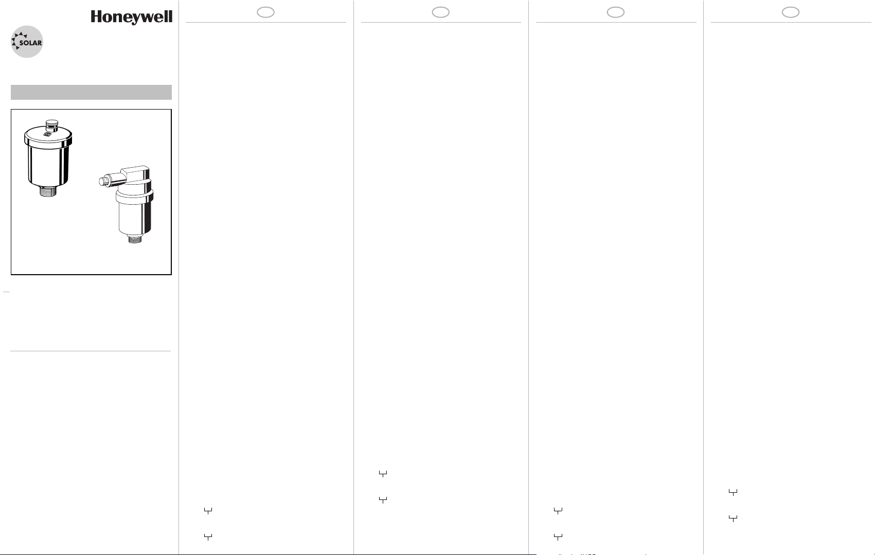
E121S
E125S
EB-E121S/E125S Rev. B
Automation and Control Solutions
Honeywell GmbH
Hardhofweg
D-74821 Mosbach
Phone: (49) 6261 810
Fax: (49) 6261 81309
http://europe.hbc.honeywell.com
www.honeywell.com
Manufactured for and on behalf of the
Environmental and Combustion Controls Division of
Honeywell Technologies Sàrl, Rolle, Z.A. La Pièce
16, Switzerland by its Authorised Representative
Honeywell GmbH
MU1H-1359GE23 R1108
Subject to change without notice
© 2008 Honeywell GmbH
1. Sicherheitshinweise
1. Beachten Sie die Einbauanleitung.
2. Benutzen Sie das Gerät
• bestimmungsgemäß
• in einwandfreiem Zustand
• sicherheits- und gefahrenbewusst.
3. Beachten Sie, dass das Gerät ausschließlich für
den in dieser Einbauanleitung genannten Verwendungsbereich bestimmt ist. Eine andere oder
darüber hinausgehende Benutzung gilt als nicht
bestimmungsgemäß.
4. Beachten Sie, dass alle Montage-, Inbetriebnahme,
Wartungs- und Justagearbeiten nur durch autorisierte Fachkräfte ausgeführt werden dürfen.
5. Lassen Sie Störungen, welche die Sicherheit
beeinträchtigen können, sofort beseitigen.
2. Funktionsbeschreibung
Im Inneren des Schnellentlüfters befindet sich ein
Schwimmer, der in Abhängigkeit des Wasserstandes
über einen Hebel ein Ventil betätigt. Befindet sich im
Schwimmergehäuse kein Wasser, so zieht der
Schwimmer das Ventil in Offenstellung. Beim Füllen
der Heizungsanlage kann so die vorhandene Luft
entweichen. Nach dem Füllen der Anlage wird der
Schwimmer durch das einströmende Wasser angehoben und das Ventil schließt. Wasser enthält normalerweise einen Sauerstoffanteil, der beim Betrieb der
Heizungsanlage entgast und sich an den höchsten
Stellen der Anlage sammelt. Deshalb muss der
Schnellentlüfter an den Sammelpunkten (höchster
Punkt am Heizkessel, Ende der Steigleitung) eingebaut werden.
3. Verwendung
Medium Wasser
Mediumstemperatur max. 150 °C
Nicht geeignet für Dampf.
4. Technische Daten
Nenndruck E121S max.10 bar
Nenndruck E125S max.18 bar
Betriebsdruck 0,5 - 10 bar
Anschlussgröße R
3
/8" und R 1/2"
5. Lieferumfang
Der Schnellentlüfter besteht aus:
•Deckel
• Gehäuse
• Schwimmer mit Feder
• Ventilsitzdichtung
6. Varianten
E121S...A = Standardausführung
Anschlussgröße
E125S...A = Standardausführung
Anschlussgröße
1. Safety Guidelines
1. Follow the installation instructions.
2. Use the appliance
• according to its intended use
• in good condition
• with due regard to safety and risk of danger.
3. Note that the appliance is exclusively for use in the
applications detailed in these installation instructions. Any other use will not be considered to
comply with requirements and would invalidate the
warranty.
4. Please take note that any assembly, commissioning, servicing and adjustment work may only be
carried out by authorized persons.
5. Immediately rectify any malfunctions which may
influence safety.
2. Functional description
Inside the automatic air vent there is a floater which
operates a lever according to the water level. When
there is no water in the housing, then the floater opens
the valve. Air can therefore be vented from the heating
system during filling. When the heating system has
been filled, the inflowing water closes the valve and the
vent is shut off. Water usually contains oxygen which
bubbles off during operation of the system and collects
at the highest point. The automatic air vent must therefore be fitted at the air collection position (highest point
on a boiler or pipework circuit).
3. Application
Medium Water
Medium temperature max. 150 °C
Not suitable for steam.
4. Technical data
Nominal pressure E121S max.10 bar
Nominal pressure E125S max.18 bar
Operating pressure 0,5 - 10 bar
Connection size R
3
/8" and R 1/2"
5. Scope of delivery
The automatic air vent comprises:
•Lid
• Housing
• Floater with spring
• Valve seat seals
6. Options
E121S...A = Standard version
Connection size
E125S...A = Standard version
Connection size
1. Avvertenze di sicurezza
1. Rispettare le istruzioni di montaggio.
2. Utilizzare l'apparecchio
• secondo la destinazione d'uso
• in uno stato perfetto
• in modo sicuro e consapevoli dei pericoli connessi
3. Si prega di considerare che l'apparecchio è realizzato esclusivamente per il settore d'impiego riportato nelle presenti istruzioni d'uso. Un uso differente
o diverso da quello previsto è da considerarsi
improprio.
4. Osservare che tutti i lavori di montaggio, di messa
in funzione, di manutenzione e di regolazione
devono essere eseguiti soltanto da tecnici specializzati e autorizzati.
5. I guasti che potrebbero compromettere la sicurezza
devono essere risolti immediatamente.
2. Descrizione del funzionamento
All'interno dello valvola a sfogo si trova un galleggiante
che, a seconda del livello dell'acqua, aziona una
valvola tramite una leva. Se nella corpo non è presente
acqua, il galleggiante mantiene la valvola in posizione
aperta. Durante il riempimento dell'impianto di
riscaldamento, l'aria presente al suo interno può così
fuoriuscire. Una volta riempito l'impianto, il galleggiante viene sollevato dall'acqua in arrivo e la valvola
si chiude. Di norma, l'acqua contiene una percentuale
di ossigeno che si degassa durante il funzionamento
dell'impianto di riscaldamento e si accumula nei punti
più alti dell'impianto. Lo valvola a sfogo deve quindi
essere montato nei punti di raccolta (punto più alto
della caldaia, estremità della tubazione montante).
3. Uso
Mezzo Acqua
Temperatura mezzo max. 150 °C
Non idoneo per vapore
4. Dati tecnici
Pressione nominale E121S max.10 bar
Pressione nominale E125S max.18 bar
Pressione di esercizio 0,5 - 10 bar
Dimensioni attacchi R
3
/8" e R 1/2"
5. Fornitura
Lo valvola a sfogo è costituito da:
• Coperchio
•Scatola
• Galleggiante con molla
• Guarnizione della sede della valvola
6. Varianti
E121S...A = Modello standard
Dimensioni attacchi
E125S...A = Modello standard
Dimensioni attacchi
1. Indicaciones de seguridad
1. Siga las instrucciones de montaje.
2. Utilice el aparato
• conforme a lo previsto
• en estado correcto
• teniendo en cuenta los riesgos y la seguridad.
3. Tenga en cuenta que la válvula ha sido diseñada
exclusivamente para las aplicaciones indicadas en
estas instrucciones de montaje. Una utilización
distinta no se considerará conforme a lo previsto.
4. Tenga en cuenta que los trabajos de montaje, de
puesta en funcionamiento, de mantenimiento y de
ajuste sólo deben efectuarlos técnicos especialistas autorizados.
5. Solucione de inmediato los fallos que puedan
afectar a la seguridad.
2. Descripión de funcionamiento
En el interior del purgador de aire automático hay un
flotador, el cual acciona una válvula mediante palanca
según el nivel del agua. Si no hay agua en la carcasa
del flotador, éste tira de la válvula a la posición abierta.
De esta forma, al llenar el radiador el aire existente
puede escapar. Después de llenar la instalación, el
agua introducida eleva el flotador y la válvula se cierra.
El agua contiene normalmente una parte de oxígeno
que se desgasifica durante el funcionamiento del radiador y se acumula en el punto más alto de la instalación. Por este motivo debe montarse el purgador de
aire automático en los puntos colectores (el punto más
alto de la caldera, extremo de la tubería ascendente).
3. Rango de aplicación
Medio Agua
Temperatura del agente max. 150 °C
No adecuado para vapor.
4. Datos técnicos
Presión nominal E121S max.10 bar
Presión nominal E125S max.18 bar
Presión de servicio 0,5 - 10 bar
Tamaño de la conexión R
3
/8" y R 1/2"
5. Suministro
El purgador de aire automático se compone de:
• Tapa
•Carcasa
• Flotador con resorte
• Junta de asiento de válvula
6. Suministro
E121S...A = Ejecución de serie
Tamaño de la conexión
E125S...A = Ejecución de serie
Tamaño de la conexión
Page 2
D GB I ES
7. Montage
7.1 Einbauhinweise
• Einbau an den höchsten Punkten der Anlage, sowie
überall dort , wo sich Luftansammlungen bilden
können
• Einbau in die Vorlaufleitung auf der Druckseite der
Pumpe empfohlen
• Um Funktionsstörungen durch von außen eingetragene Schmutzteilchen zu vermeiden, sollte die
Ventilkappe auf dem Schnellentlüfter verbleiben
- Er ist damit absolut tropffrei
7.2 Montageanleitung
1. Rohrleitung gut ausblasen oder ausspülen
2. Absperrventil unter den Schnellentlüfer montieren
- ermöglicht Wartung ohne Entleeren der Anlage
3. Der Schnellentlüfter muss senkrecht eingebaut
werden
4. Der untere Teil des Absperrventils muss in einen
ausreichend großen freien Querschnitt der Rohrleitung eingebaut werden
5. Abdichtung erfolgt mittels O-Ring (3/8") oder Dichtungen (1/2") am Gehäuseboden
8. Inbetriebnahme
1. Rändelkappe zwei Umdrehungen öffnen
9. Instandhaltung
9.1 Inspektion
Der Schnellentlüfter muß regelmäßig überprüft
werden, da es durch Schmutzansammlungen zu Fehlfunktionen kommen kann.
10. Entsorgung
• Gehäuse aus Messing
• Deckel aus Messing
• Schwimmer aus hochwertigem, temperaturbeständigem Kunststoff
• Feder aus Edelstahl
• Dichtungsteile aus temperatur- und alterungsbeständigem Elastomer
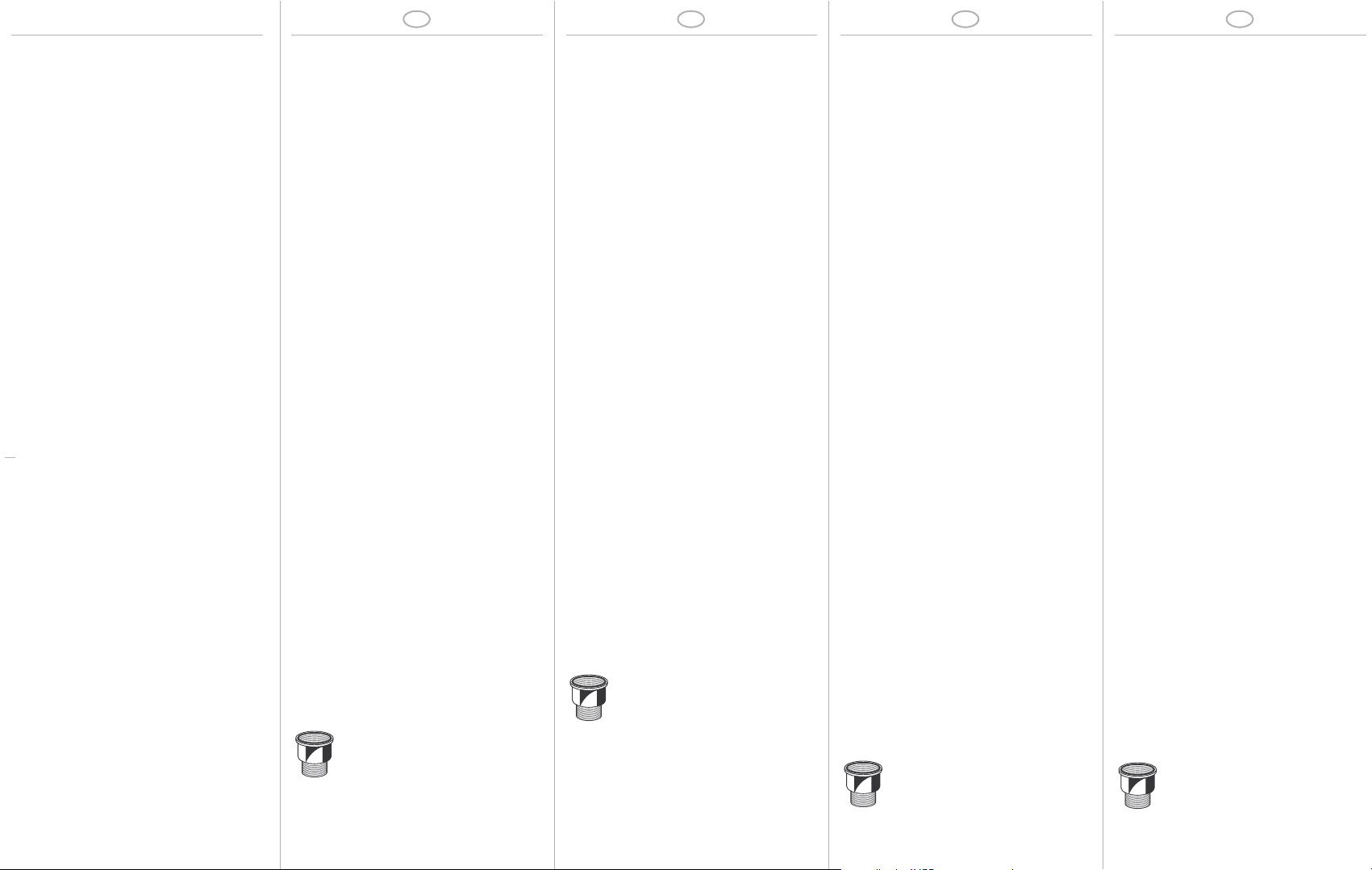
11. Zubehör
Absperrventil
Gehäuse aus Messing, Innenteile aus hochwertigem
temperaturbeständigem Kunststoff, Dichtring aus
heißwasserbeständigem Elastomer
für 3/8" AVSOLAR-3/8
für 1/2" AVSOLAR-1/2
7. Assembly
7.1 Installations Guidelines
• Install at the highest points of the system, as well as
anywhere where air accumulations can form
• Installation in the flow pipe on the pressure side of
the pump is recommended
• The valve cap should remain on the air vent in order
to prevent functional disruption due to dirt particles
that have entered from the outside
- Therefore the air vent is absolutely drip free
7.2 Assembly instructions
1. Blow out or rinse pipe line out well
2. Mount shutoff valve under the air vent
- enables maintenance without emptying the
system
3. The air vent must be installed vertically
4. The lower part of the shutoff valve must be installed
in a sufficiently large free cross-section of the pipe
5. Sealing is produced by means of the O-rings (3/8")
or sealings (1/2") at the housing floor
8. Commissioning
1. Open knurled cap two rotations
9. Maintenance
9.1 Inspection
The air vent must be examined regularly, since
malfunctions can occur due to dirt accumulation
10. Disposal
• Brass housing
• Brass lid
• High grade, heat-resistant synthetic material float
• Stainless steel spring
• Temperature- and aging-resistant elastomer
sealing parts
11. Accessories
Shutoff valve
Brass housing, high-grade, temperature-resistant
plastic internal parts, hot water-resistant elastomer
sealing ring
for 3/8" AVSOLAR-3/8
for 1/2" AVSOLAR-1/2
7. Montaggio
7.1 Istruzioni di installazione
• Montaggio nei punti più alti dell'impianto e in tutti i
punti in cui si possono formare accumuli d'aria
• Consigliato il montaggio nella tubazione di
mandata, sul lato pressione della pompa
• Per evitare malfunzionamenti causati da infiltrazioni
di sporco dall'esterno, il tappo della valvola
dovrebbe rimanere sullo valvola a sfogo
- Con il tappo, lo sfiato è completamente sigillato
7.2 Istruzioni di montaggio
1. Soffiare o sciacquare bene la tubazione
2. Montare la valvola d'intercettazione sotto allo
valvola a sfogo
- Permette una manutenzione senza dover svuo-
tare l'impianto
3. Lo valvola a sfogo deve essere montato in posizione verticale
4. La parte inferiore della valvola d'intercettazione
deve essere montata in una sezione libera (di
dimensioni sufficienti) della tubazione
5. La sigillatura avviene tramite l'O-ring (3/8") o guarnizioni (1/2") da montare nel parte inferiore della
valvola sfogo
8. Messa in funzione
1. Aprire di due giri il tappo zigrinato
9. Manutenzione
9.1 Ispezione
Lo valvola a sfogo deve essere controllato a intervalli
regolari, perché gli accumuli di sporco possono
causare malfunzionamenti.
10. Smaltimento
• Scatola in ottone
• Coperchio in ottone
• Galleggiante in pregiata plastica resistente ad alte
temperature
• Molla in acciaio inox
• Guarnizioni in elastomero resistente ad alte temperature e all'invecchiamento
11. Accessori
Valvola d'intercettazione
Sede in ottone, componenti interni in pregiata plastica
resistente ad alte temperature, anello di tenuta in elastomero resistente all'acqua calda
Per 3/8" AVSOLAR-3/8
Per 1/2" AVSOLAR-1/2
7. Montaje
7.1 Notas para el montaje
• Montaje en los puntos más altos de la instalación,
así como allí donde pueda acumularse aire
• Se recomienda el montaje en la tubería de ida en el
lado de la presión de la bomba
• Para evitar anomalías en el funcionamiento
debidas a partículas de suciedad exteriores, la tapa
de la válvula debería mantenerse sobre el purgador
de aire automático
- De esta forma se evita completamente cualquier
goteo
7.2 Instrucciones de montaje
1. Soplar o aclarar bien la tubería
2. Montar la válvula de retención debajo del purgador
de aire automático
- Permite el mantenimiento sin necesidad de
vaciar la instalación
3. El purgador de aire automático debe montarse en
vertical
4. La parte baja de la válvula de retención debe
montarse en una sección libre de la tubería lo
suficientemente grande
5. La obturación se realiza en la base de la carcasa
mediante la junta tórica (3/8") o juntas (1/2")
8. Puesta en servicio
1. Abrir la tapa moleteada dos giros
9. Mantenimiento
9.1 Inspección
Debe revisarse regularmente el purgador de aire
automático ya que puede producirse un funcionamiento incorrecto debido a suciedad acumulada.
10. Residuos
• Carcasa de latón
• Tapa de latón
•
Flotador sintético de alta calidad y resistencia térmica
• Resorte de acero inoxidable
• Juntas de elastómero de resistencia térmica y resistencia al envejecimiento
11. Accesorios
Válvula de retención
Carcasa de latón, piezas interiores sintéticas de resistencia térmica y alta calidad, anillo obturador de elastómero resistente al agua caliente
para 3/8" AVSOLAR-3/8
para 1/2" AVSOLAR-1/2
 Loading...