

Page 1
I
1. Installazione
Per l’installazione è necessario osservare
le prescrizioni locale, le direttive e le
istruzioni di installazione generali.
L’impianto deve essere installato in un
luogo resistente al gelo e ben accessibile.
1.1 Montaggio
1. Sciacquare bene la tubazione.
2. Avvitare la valvola di sfogo al punto più
alto dell’impianto di riscaldamento.
☞ Utilizzare la chiave fissa e serrare a
fondo.
2. Manutenzione
La valvola di sfogo deve essere controllato
regolarmente in quanto possono verificarsi
difetti di funzionamento dovuti ad accumuli
di sporco.
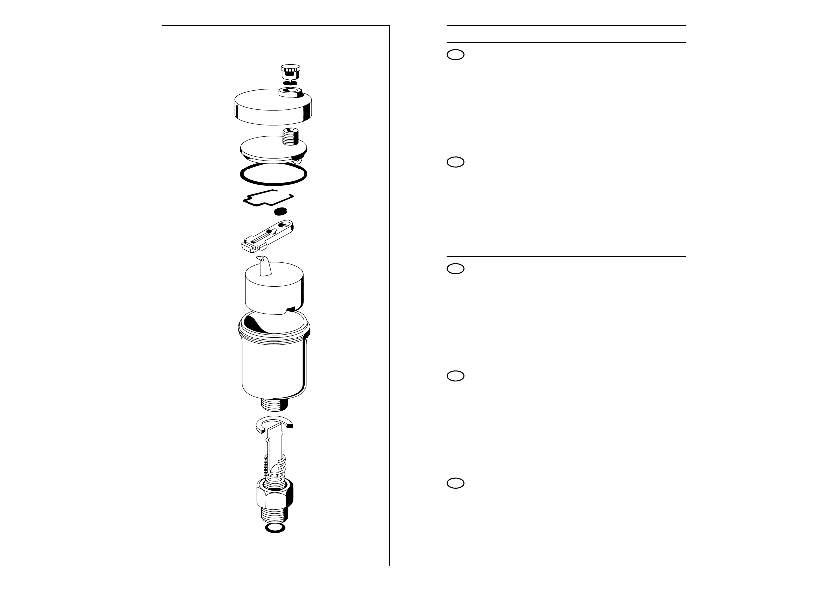
1. Svitare il coperchio insieme al
galleggiante.
2. Pulire accuratamente tutte le parti e
rimontarle.
3. Controllare che la calotta sia aperta.
E 121
Einbau-Anleitung . Installation Instruction . Instructions de montage
Installatievoorschrift . Istruzioni per il montaggio
3. Settore d’impiego
Impianti di riscaldamento acqua calda.
Non adatto per oli minerali o liquidi con
additivi a base di oli minerali.
4. Dati tecnici
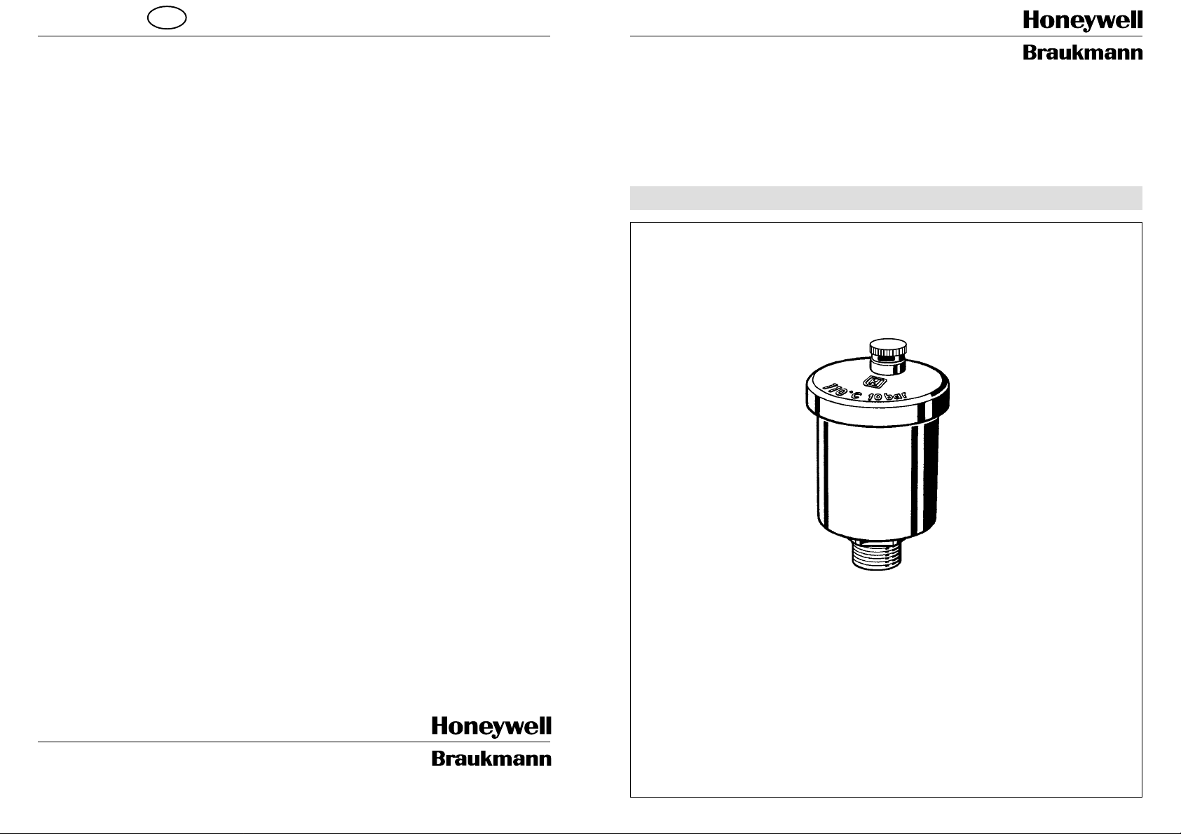
Temperatura d’esercizio max. 110 °C
Pressione d’esercizio max. 10 bar
Dimensioni raccordo R 3/8" o R 1/2"
5. Accessori
Z 121 - 3/8 Valvola di chiusura 3/8"
Z 121 -
Braukmann Armaturen
Honeywell AG
Hardhofweg . D-74821 Mosbach
1
/ Valvola di chiusura 1/2"
07/99
Schnellentlüfter
Automatic air vent
Désaérateur rapide
Snelontluchter
Valvola di sfogo
EB-E121 =A
Page 2
Inhaltsübersicht Seite
D
1. Einbau 2
2. Wartung 2
3. Verwendungsbereich 2
4. Technische Daten 2
5. Zubehör2
Index Page
GB
1. Installation 2
2. Maintenance 2
3. Field of application 2
4. Technical Data 2
5. Accessories 2
Index Page
F
1. Installation 3
2. Maintenance 3
3. Utilisations 3
4. Caractéristiques techniques 3
5. Accessoires 3
Index Page
NL
1. Installatie 3
2. Onderhoud 3
3. Toepassingsgebied 3
4. Technische gegevens 3
5. Toebehoren 3
Index Page
I
1. Installazione 4
2. Manutenzione 4
3. Settore d`impiego 4
4. Dati tecnici 4
5. Accessori 4
Page 3

D NLF
GB
1. Einbau
Beim Einbau sind die örtlichen Vorschriften,
sowie allgemeine Richtlinien und die EinbauAnleitung zu beachten. Der Einbauort muß
frostsicher und gut zugänglich sein.
1.1 Montage
1. Rohrleitung gut durchspülen.
2. Schnellentlüfter an der höchsten Stelle
der Heizungsanlage in eine Rohrleitung
einschrauben.
☞ Gabelschlüssel verwenden und fest
einschrauben.
2. Wartung
Der Schnellentlüfter muß regelmäßig
überprüft werden, da es durch Schmutzansammlungen zu Fehlfunktionen kommen
kann.
1. Deckel abschrauben und zusammen mit
Schwimmer entnehmen.
2. Alle Teile vorsichtig reinigen und wieder
zusammenbauen.
3. Prüfen ob die Kappe geöffnet ist.
1. Installation
The local regulations, as well as the
general instructions and installation
instructions must be observed when
installing. The mounting place must
be free from frost and accessible at all
times.
1.1 Assembly
1. Flush pipe thoroughly.
2. Screw air vent at the highest position of
the heating plant into a pipe.
☞ Use fork wrench and screw-in
tightly.
2. Maintenance
The air vent must be checked regularly,
since dirt can lead to malfunctions.
1. Unscrew and remove cover together
with float.
2. Clean all parts carefully and assemble
again.
3. Check if cap is open.
1.Installation
Pendant l’installation, respecter les
prescriptions locales, les directives à
caractère général et la notice d’installation.
Le lieu d’implantation doit être protégé
contre le gel et facilement accessible.
1.1 Montage
1. Bien rincer la conduite.
2. Visser le désaérateur rapide sur une
conduite sur le point le plus élevé de
l’installation de chauffage.
☞ Utiliser une clé à fourche et serrer à
bloc.
2. Maintenance
Le désaérateur rapide doit être vérifié
régulièrement du fait que l’encrassement
peut provoquer des dysfonctionnements.
1. Dévisser le couvercle et déposer avec
le flotteur.
2. Nettoyer soigneusement toutes les
pièces et remonter.
3. Vérifier si le bouchon est ouvert.
1. Installatie
Bij de installatie dienen de plaatselijke
voorschriften alsmede de algemene
richtlijnen en de installatiehandleiding in
acht te worden genomen. De installatieplek
dient vorstvrij en goed toegankelijk te zijn.
1.1 Montage
1. Spoel de pijpleiding goed door.
2. Bevestig de snelontluchter met bouten
op de hoogste plek van de
verwarmingsinstallatie in een ijpleiding.
☞ Gebruik een steeksleutel en draai
de bouten goed aan.
2. Onderhoud
De snelontluchter moet regelmatig worden
geïnspecteerd omdat door opeenhoping
van vuil storingen kunnen optreden.
1. Schroef het deksel los en verwijder het
samen met de vlotter.
2. Reinig voorzichtig alle onderdelen en
monteer het geheel weer.
3. Controleer of de kap open staat.
3. V erwendungsbereich
Warmwasser-Heizungsanlagen.
Nicht geeignet für Mineralöl oder Flüssigkeiten mit Zusätzen auf Mineralölbasis.
4. Technische Daten
Betriebstemperatur max. 110 °C
Betriebsdruck max. 10 bar
Anschlußgrößen R
3
/8" oder R 1/2"
5. Zubehör
Z 121 - 3/8 Absperrventil 3/8"
Z 121 -
1
/2 Absperrventil 1/2"
3.Range of application
Warm-water heating plants.
Not suitable for mineral oil or liquids
with addition on a mineral oil basis.
4.T echnical Data
Operating temperature max. 110 °C
Operating pressure max. 10 bar
Connection sizes R
3
/8" or R 1/2 "
5. Accessories
Z 121 - 3/8 shutoff valve 3/8"
Z 121 -
2 3
1
/2 shutoff valve 1/2"
3.Utilisations
Installations de chauffage à eau chaude.
Non utilisable pour l’huile minérale et les
liquides avec des additifs dérivés d’huile
minérale.
4. Caractéristiques techniques
Température de service : max. 110 °C
Pression de service : max. 10 bar
Raccords : R
3
/8" ou R 1/2 "
5. Accessoires
Z 121 - 3/8 vanne d’isolement 3/8"
Z 121 -
1
/2 vanne d’isolement 1/2"
3. Toepassingsgebied
Warmwaterinstallaties.
Niet geschikt voor minerale olie of
vloeistoffen met toevoegingen op basis van
minerale olie.
4. T echnische gegevens
Bedrijfstemperatuur max. 110 °C
Werkdruk max. 10 bar
Aansluitmaten R
3
/8" of R 1/2"
5. T oebehoren
Z 121 - 3/8 afsluiter 3/8"
Z 121 -
1
/2 afsluiter 1/2"
 Loading...