

Page 1
AUTOMATIC BYPASS AND DIFFERENTIAL PRESSURE VALVE
FOR INSTALLATION IN DISTRICT HEATING SYSTEMS
Design
The automatic bypass and differential pressure valve comprises:
•
Body with internally threaded inlet and outlet
•
Spring bonnet
•
Adjustment facility
•
Valve disc
•
Spring
Materials
•
Unpolished brass housing
•
Untreated brass spring bonnet
•
High-quality synthetic material adjus ter knob
•
Brass valve disc
•
Stainless-steel spring
•
EPDM seals
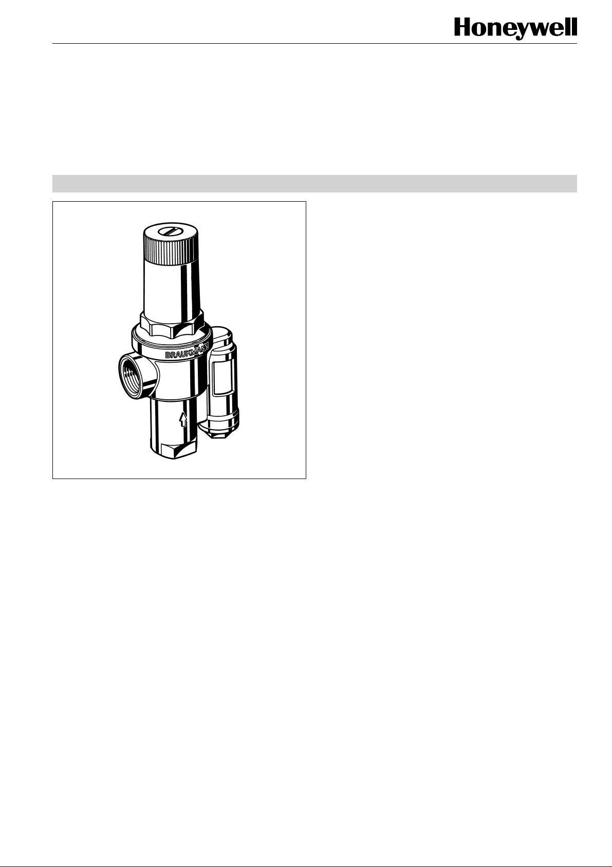
DU146 M
PRODUCT DATA
Application
The DU146 M automatic bypass and differential pressure
valve is used to maintain constant differential pressure in a
heating system. It reduces flow noise in a system, particularly
as thermostatic radiator valves are closing. The boiler return
temperature is raised and this reduces the corrosion caused
by flue gas condensation. In addition, when radiator valves
are closed it also maintains flow over the temperature sensor
on the boiler to ensure proper operation of external temperature compensating controls. On gas fired water heaters it
guarantees a minimum flow circulation when thermostats or
radiator valves are closed.
Features
• Simple installation between the flow and return pipe-
work
• Minimises flow noise
• No external controls required
• Differential pressure finely adjustable
• Problemlose Einregulierung durch eingebaute
Differenzdruck-Istwertanzeige
• Hinders boiler corrosion
• Setting value is in meters water column
• Tried and tested
Range of Applicati on
For pumped hot water heating systems
Specifications
Medium
Operating temperature
Operating pressure
Differential pressure
Connection size
Hot water
max. 130°C (230°F)
max. 16 bar (232 P.S.I.)
Adjustable between
0,05...0,5 bar (0,7...7,3 P.S.I.)
Set during manufacture at
0,2 bar (2,9 P.S.I.)
3/4" and 1 1/4"
Copyright © 2001 Honeywell AG • All rights reserved EN0H-182GE25 R0301
Page 2
DU146 M
Function
At equal pressure between the inlet and outlet side the valve
is closed. The valve disc is pushed by a spring against the
valve seat. If there is a pressure difference between the inlet
and outlet sides, then a force is exerted on the valve disc and
against the spring. If this force exceeds the force of the
spring, then the valve begins to open in proportion to the rise
in differential pressure and maintains a constant bypas s flow
as indicated on the flow diagram.
Versions
A = Standard version
Special version on request
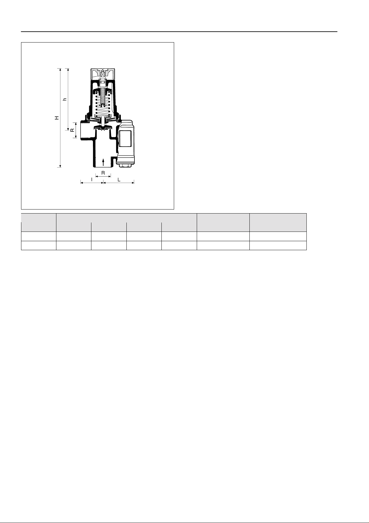
Dimensions Flow rate V m3/hType R
L I H h
3/4" 36 50 160 100 3 DU146M-3/4A
1 1/4" 51 58 213 155 10 DU146M-1 1/4A
.
Ordering-No.
EN0H-182GE25 R0301 2 Honeywell AG • All rights reserved
Page 3

DU146 M
Installation Guidelines
•
Simple installation between flow and return
•
For maintenance purposes it is recommended that shutoff
valves be fitted on both sides of the bypass valve
Flow Diagram
Typical Applications
Automatic bypass and differential pressure valves are installed in heating systems to maintain a constant differential
pressure and to minimise water flow noise.
DU146 M valves are specifically designed for district heating
schemes, but they can also be used for heating installations
with three and four way mixer valves, for example on gas
fired hot water circulation systems
Turns
Honeywell AG • All rights reserved 3 EN0H-182GE25 R0301
Page 4

DU146 M
Home and Buil ding Control
Honeywell AG Phone: (49) 2932 9880
Zu den Ruhrwiesen 3 Fax: (49) 2932 988239
D-59755 Arnsberg-Neheim mng@honeywell.com http://europe.hbc.honeywell.com
EN0H-182GE25 R0301 4 Subject to change • All rights reserved
 Loading...