

Page 1
e
n
e
r
g
www.energysavingtrust.org.uk
g
n
i
v
a
s
y
DU144
Automatic Bypass Valve
INSTALLATION INSTRUCTIONS
Building Regulations
An Automatic Bypass Valve (DU144) controls water flow in the Heating Circuit according to the water pressure
across it and is used to maintain a minimum flow rate through the boiler and to limit circulation pressure when other
water paths are closed.
A bypass circuit must be installed if the Boiler manufacturer requires one, or specifies that a minimum flow rate has
to be maintained whilst the Boiler is firing.
The use of Automatic Bypass Valves becomes particularly important when Heating Systems include large numbers
of Thermostatic Radiator Valves (TRVs) – whilst the TRVs are open the Automatic Bypass Valve remains closed,
however, as the TRVs start to close, the Automatic Bypass Valve starts to open maintaining the required water
flow through the boiler. Using an Automatic Bypass Valve is also likely to reduce noise in systems caused by
excess water velocities.
Because manual or fixed position valves do not regulate the flow and allow water to bypass even when it is not
necessary, Building Regulations require bypass circuits to use Automatic Bypass Valves and not fixed position
valves.
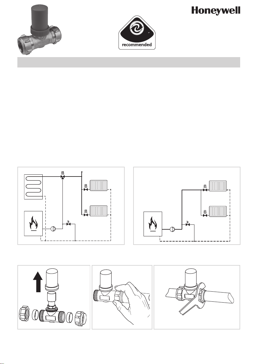
Location in System
Installation
Remove protective cap to set
04 100 25 001 000 EN2H-0286GE25 R0207
ABV
TRV
TRV
Install the DU144 with flow in
the direction of the Arrow on
the Body
TRV
TRV
ABV
System with combi boilerSystem with stored hot water
Use a correctly sized open ended
spanner to tighten.
Do not over tighten.
Page 2
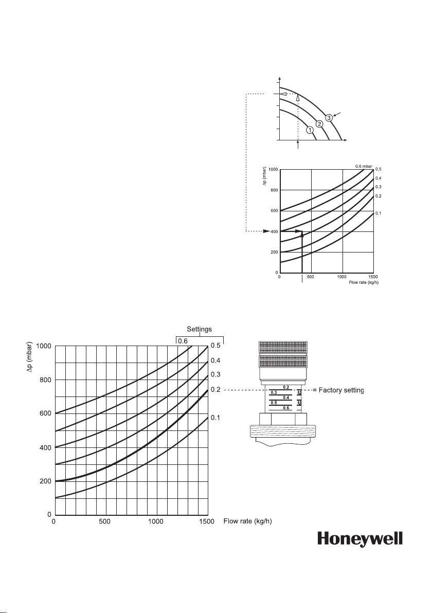
Setting Procedure
1) Commission and balance the Heating System –
take note of the selected pump speed.
2) Using the Boiler manufacturer’s instructions, find
the minimum flow requirement for the Boiler.
3) Using the Pump manufacturer‘s Pump curves
determine the available Pump head when
operating at the required minimum flow and the
selected Pump speed.
4) Using the DU144 Setting chart, the calculated
Pump Head and the minimum Boiler Flow to find
the optimum setting for the DU144
Note: To set the DU144, remove the protective cap
and turn the setting handle until the bottom of
the handle crosses the corresponding line on the
DU144 stem.
Note: The cap is internally fixed with sealing wax
during assembly. Turn firmly to break the seal.
Should persistent water velocity noise occur in the
Heating System, gradually turn the DU144 to a lower
setting until the noise is eliminated.
Important: replace protective cap after setting the
DU144 to avoid tampering
Example:
Minimum flow 300 l/h - Pump speed 3.
Pump chart indicates 4 m head (Use Pump
Manufactures chart).
Pump Head
3) Available head
(example 4m)
5) Available head
(example 4m)
5m
4m
3m
2m
1m
2) 300 l/h Boiler min. flow
4) Minimum flow
(example 300 l/h)
Pump Speed
Flow l/h
Using DU144 Setting Chart:
4m Head / Minimum Flow 300 l/h
Result = Set DU144 to setting 0.35
Note: For pre-setting use
line below the
number
Honeywell Control Systems Ltd.
Honeywell House
Arlington Business Park
Bracknell, Berkshire RG12 1EB
Phone: 01344 656000
Fax: 01344 656240
Manufactured for and on behalf of the Environment and Combustion Controls Division of Honeywell Technologies Sàrl, Ecublens, Route du Bois 37, Switzerland by its Authorised Representative Honeywell GmbH
Subject to change • All rights reserved
EN2H-0286GE25 R0207
© 2007 Honeywell International Inc.
 Loading...