

Page 1
DT900AM Series DUAL TEC® Motion Sensor for Commercial
and Light Industrial Applications—Installation Instructions
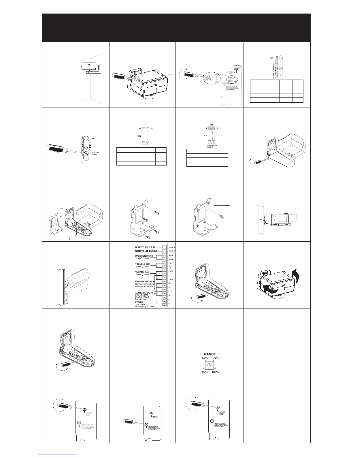
Step 1
Select mounting height.
Step 2
Carefully push screwdriver into slots
to disengage latches and open top
cover.
Step 3
DT906AM ONLY: Firmly insert
screwdriver into slot in arrow and
rotate PIR Mirror Selector to the
correct range.
Step 5
Locate correct sensor range scale
and rotate Vertical Adjustment Screw
until the diamond corresponds to the
sensor mounting height (coarse
adjust).
Step 6
Set switch S3 to establish the
sensitivity best suited to your application.
Step 7
Select INFORMER
®
mode with switch
S2, if desired. (See INFORMER Mode
section).
SENSITIVITY
HIGH (Pulse Count 1)
NORMAL (Pulse Count 2)
LOW (Pulse Count 3)
H*
N
L**
S3
*Factory default setting; recommended setting
for DT906AM. **Not connected.
Step 8
Carefully push screwdriver into slot
to disengage latch and remove
bottom cover.
Step 9
Unfasten screws and remove mounting plate from sensor. If required,
remove the knockout to allow wire
entry via electric metallic tubing or
surface wiring conduit.
Step 10
Attach mounting plate to wall at
desired height, using four screws
(not supplied).
Step 11
Install M5 (#10) screw (not supplied)
in wall 1.9 cm (3/4”) below mounting
screw, as shown, for tamper activation.
Step 12
Pull about 30 cm (12”) of wire from
wall through the opening in the
mounting plate and route wire to the
terminal strip.
Step 13
Hang the sensor on the mounting
plate hooks and fasten with the two
mounting plate screws.
Step 14
Wire the
unit as
shown.
Use
0.8 - 1.5 mm
(22-16 AWG).
NOTE: Secure
wires to
mounting plate
with tie wraps.
Step 15
Loosen horizontal locking screw in
sensor support base.
Step 16
Grasp housing and rotate it to the
desired position (coarse adjust). If
fine adjust is needed see Steps 21-
23.
NOTE: Reference marks = 5° change.
Step 18
Apply power to the sensor, and all
the LED’s will start flashing rapidly.
Wait 90 seconds for the power-up
self-test to finish, at which point, if
there is no motion in the detection
area, all the LED’s will be off, and the
sensor will be ready for walk testing.
If the three LED’s do not go off after
90 seconds, refer to the Troubleshooting section.
1.9 cm (3/4”)
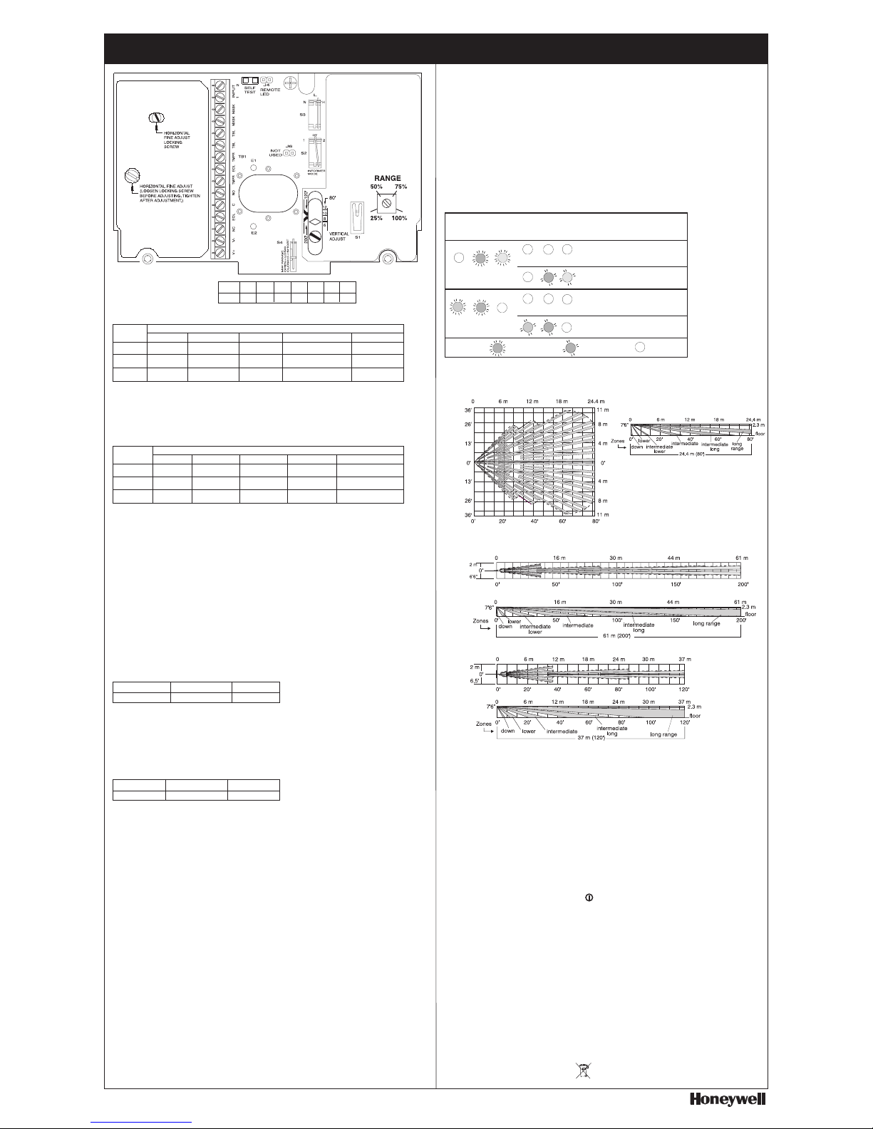
Step 21
For fine horizontal adjustment, loosen
the PIR horizontal fine locking screw
on the PCB.
Step 23
Tighten the horizontal fine locking
screw on the PCB.
NOTE: Fine adjustment allows for small
changes (3 degrees right or left) between
coarse settings.
Step 22
Rotate the horizontal fine adjust knob
to the desired position.
30 cm (12”) minimum
*Factory default setting.
Step 4
Set switch S4 to establish microwave
range.
Step 17
Tighten horizontal locking screw in
sensor support base.
Step 24
Remove the jumper at J4 on the PCB
to disable the LEDs after walktesting, and complete installation by
closing the top cover and replacing
the bottom cover.
NOTE: Fine adjust may be needed during
walk-test. (See Troubleshooting section.)
2 m (6’)
4 m (12’)
Step 20
Walk-test the sensor to check for
adequate detection coverage and to
verify the sensor is fully functional.
Depending on the selected sensitivity level, the sensor will alarm after
taking between 2 and 4 steps in the
detection pattern.
NOTE: If an on-going trouble, mask or
INFORMER condition occurs, the LEDs will
display a pattern that identifies the trouble.
(See the Troubleshooting section).
Step 19
Turn the microwave potentiometer
counterclockwise to decrease the
microwave range to minimum.
During walk-test, gradually turn the
potentiometer clockwise increasing
microwave sensitivity until the
desired range is obtained.
Optimal
Mounting
Height
2.3m (7’6”)
Mounting Location Guidelines
• Avoid direct or reflected sunlight
• Aim sensor away from windows, heating/
cooling devices or large moving objects.
• Sensor must have a clear line-of-sight to
protected area
INFORMER MODE
OFF
MODE 1
MODE 2
S2
OFF*
1
2
*Factory default setting (not connected).
Knockout
MODEL RANGE
Switch S4
MIRROR
Selector
DT906AM 61 m (200’) OPEN* 200’ *
DT906AM
37 m (120’) CLOSED 120’
DT900AM 24.4 m (80’) OPEN* N/A
DT900AM 15 m (50’) CLOSED N/A
Page 2
DT900AM Series DUAL TEC® Motion Sensor Product Information
6 8 10 12 80 120 200
1.8 2.4 3 3.7 24.4 37 61
Feet
Meters
Red
Yellow
Green
Normal
ON
Alarm
ON
Microwave
ON
PIR
Power Up/Trouble
1
Rapid Flash
Rapid Flash
Rapid Flash
Mask
Rapid Flash
OFF
Rapid Flash
Microwave INFORMER
1,2
Rapid Flash
Rapid Flash
OFF
OPERATION MODE
Figure 1
DT900AM
Printed Circuit Board (PCB)
LED INDICATORS
LED
PIR INFORMER
1,2
Rapid Flash
OFF
Rapid Flash
1
If a Trouble or INFORMER condition LED pattern disappears before being noted, initiate a self test (see Self Test section),
and the sensor will show the last LED pattern stored in the sensor’s memory. To clear this display, initiate another self test.
2
The noted LED patterns will only occur when no motion is present in the detection pattern. For additional microwave
and PIR INFORMER mode LED information, see the Troubleshooting section.
NOTE: LED’s operate as listed only when the LED’s are enabled (see LED Enable section).
Alarm Relay
Trouble Relay
Mask Relay
Normal
Closed
Closed
Closed
Intrusion
Open
Closed
Closed
Trouble
1
Closed
Open
Closed
Mask
1
Closed
Closed
Open
OPERATION MODE
RELAY OPERATION
Relay
PIR/MW INFORMER
2
Closed
Open
Closed
1
In a Trouble or Mask condition, the Trouble relay or Mask relay (respectively) will latch open until the condition has been
cleared. For more information, see the Troubleshooting section.
2
For information on INFORMER conditions, see the INFORMER Troubleshooting Matrix in the Troubleshooting section.
MASK FUNCTION
Normal Anti-Mask Operation
The DT900AM series features an anti-mask function that detects attempts to mask the sensor. The sensor
sends active Infra-Red beams out into the sensor’s field-of-view, and monitors for reflections from materials
that will block or cover the sensor. If the sensor registers a mask condition, it will open the mask relay and
rapidly flash the red and green LEDs. To avoid false mask alarms, follow the mounting guidelines shown in
Step 1.
Clearing an Anti-Mask Condition
Visually inspect the sensor, and remove any materials blocking the sensor’s view, and the sensor will
normally reset automatically. If the sensor remains in a Mask condition, walk test the sensor to ensure a
maximum detection range, and then cycle the sensor’s power to reset it.
LED ENABLE (Note: TS50131-2-4 Compliant)
The LED’s will only be enabled either by installing Jumper J4 or by connecting the Remote LED Enable
terminal as per the table below (see also INPUT 1 & 2 in the Product Specifications section).
High/Not Connected Low
LED’s Disabled LED’s Enabled
Remote LED Enable
NOTE: Do not fit jumper J4 at the same time as the
Remote LED Enable terminal is low, or the LED’s will
not illuminate.
SELF TEST
The sensor will perform a series of self-tests in the following instances:
• On power up
• Automatically every hour during normal operation
• On installer initiation. Self tests can be installer initiated either by momentarily short circuiting the two self
test pads on the PCB (see Figure 1), or by connecting the Remote Self Test terminal, as per the table
below. (See INPUT 1 & 2 in the Product Specifications section.)
Remote Self Test
NOTE: When a self test error occurs, the Trouble
relay will latch open and all three LED’s will flash
rapidly. If the problem persists, refer to the Troubleshooting section.
High/Not Connected Low
Normal Operation Self Test
INFORMER MODE
The INFORMER mode is a useful diagnostic tool for identifying environmental conditions that are liable to
cause installation problems.
The INFORMER circuit counts the number of events registered by both the microwave and PIR technologies,
and uses the resulting ratio to determine if either technology is working properly or is misapplied. Establish
the INFORMER mode using switch S2 (see Step 7).
Mode 1: Set S2 to position 1. In Mode 1, 32 PIR events without a microwave event will cause the unit to go
into PIR INFORMER. 128 microwave events without a PIR event will cause the unit to go into microwave
INFORMER.
Mode 2: Set S2 to position 2. In Mode 2, 16 PIR events without a microwave event will cause the unit to go
into PIR INFORMER. 16 microwave events without a PIR event will cause the unit to go into microwave
INFORMER.
NOTE: The Mode 2 setting is not recommended. Use only if INFORMER indication is required quickly.
Disabled: To disable INFORMER function, set S2 to the open (OFF) position (factory default setting).
When an INFORMER condition occurs, the trouble relay opens, and the LEDs display an INFORMER trouble
code (see the INFORMER Troubleshooting Matrix in the Troubleshooting section).
NOTE: One LED indication does not relate to one PIR or Microwave event.
TROUBLESHOOTING (Continued)
Problem: The sensor’s PIR range is too long or short.
Explanation: Various mounting locations may require fine vertical adjustment (e.g., due to uneven walls
or floors, etc.).
Solution: During the walk-test, if the PIR is short-ranged, turn the Vertical Adjust Screw counterclockwise. If
the PIR is over-ranged, turn the Vertical Adjust Screw clockwise. (See Step 5.)
Problem: A combination of the sensor’s LED’s are flashing slowly when there is no motion in the detection area.
Explanation: INFORMER mode is selected on the sensor, and there is a potential false alarm source in the
local environment.
Solution: The table below describes two trouble alerts which are reported by the INFORMER circuit. To
use this troubleshooting matrix:
1) Find the trouble alert that describes the condition of the walk-test LEDs (with no motion in the area).
2) Walk-test the sensor, carefully watching the reaction of the diagnostic LEDs.
3) Refer to the Possible Causes column of the matrix for an explanation of the way in which the
diagnostic LEDs reacted to the walk-test.
4) If no environmental sources can be found, initiate a self test. If the sensor fails the self test,
replace the sensor. If not, relocate the sensor and re-test.
NOTE: If on entering the
detection pattern the LEDs
go off, the INFORMER LED
pattern can be retrieved by
initiating a self test. (See
Note 1 in the LED Indicators section.)
INFORMER
Troubleshooting
Matrix
MW environmental problem
MW unstable
MW range too long
PIR was blocked
(Pattern disappears)
Reaction of LEDs
to Walk-Test
Condition of LEDs
with No Motion
MW
(Yellow)
ALARM
(Red)
PIR
(Green)
PIR
(Green)MW(Yellow)
ALARM
(Red)
RATIO
IMBALANCE
RATIO
IMBALANCE
Type of
Problem
RATIO
IMBALANCE
RATIO
IMBALANCE
PIR environmental problem
PIR unstable
MW range too short
Possible
Causes
PIR range too short
PIR aimed wrong
PIR not reporting
MW range too short
MW not reporting
LED Legend:
(Pattern disappears)
(Microwave INFORMER)
(PIR INFORMER)
PRODUCT SPECIFICATIONS
Range:
DT906AM
200’ Mirror - 61 m x 3 m (200' x 10')
120’ Mirror - 37 m x 3 m (120' x 10')
DT900AM
24.4 m x 21 m (80' x 69')
Power requirements:
10 - 15 VDC
50 mA (max) at 12 VDC
AC Ripple: 3V peak-to-peak
at nominal 12 VDC
Alarm relay:
Energized Form C
25 VDC, 125 mA
22 ohm series protection resistor
Trouble relay:
De-energized Form B
(Normally closed)
30 VDC, 25mA
Mask relay:
De-energized Form B
(Normally closed)
30 VDC, 25mA
Tamper Switches:
Wall, top & bottom covers
30 VDC, 25 mA (NC)
INPUT 1 (Remote LED Enable) &
INPUT 2 (Remote Self Test):
Active low (0 to 1.5V)
Inactive high (5 to V+ / Unconnected)
Microwave frequency:
X-Band; 10.687 GHz
PIR white light immunity:
6500 Lux typical
RFI immunity:
30 V/m, 10 MHz - 1000 MHz
Operating temperature:
-10
o
to 55o C / 14o to 131o F
(Indoor use environment)
Relative humidity:
5% to 95% relative humidity
(non-condensing)
PIR fields of view:
61 m (200’) Range 37 m (120’) Range 24.4 m (80’) Range
2 long 6 long 22 long
6 intermediate long 4 intermediate long 18 intermediate long
4 intermediate 4 intermediate 16 intermediate
4 intermediate lower 8 lower 12 intermediate lower
8 lower 2 down 8 lower
2 down 2 down
Sensitivity:
2 - 4 steps within field-of-view
Dimensions:
20 cm x 16.5 cm x 15.2 cm
8” x 6 1/2” x 6”
Weight:
1.36 kg
Packaged Product Approx.: 1.60 kg
Approvals/listings:
CE
PD6662:2004, prEN 50131-1:2004 and TS50131-2-4:2004
Security Grade 3, Environmental Class II.
Suitable for connection to an EN 60950 Class II Limited Power
Source in European installations.
Note: In TS50131-2-4 compliant installations, mount the
sensor at 2.3 m, select the high sensitivity setting and set
switch S4 to OPEN.
To obtain applicable EU compliance Declaration of Conformities
for this product, please refer to our Website,
http://www.security.honeywell.com/hsce/international/index.html.
For any additional information regarding the compliance of this
product to any EU specific requirements, please contact:
Quality Assurance Department,
Honeywell Security & Custom Electronics,
Newhouse Industrial Estate
Motherwell,
Lanarkshire ML1 5SB,
Scotland,
United Kingdom.
Tel: +44(0)1698 738200
Email: UK64Sales@Honeywell.com
TROUBLESHOOTING
Problem: All three LED’s are flashing rapidly (LED’s are enabled), and the Trouble relay is activated.
Explanation: The sensor is in one of the following three conditions:
Power Up: The sensor is still warming up.
Low Voltage: The sensor’s supply voltage is too low.
Self Test Failure: The sensor has failed one of its internal tests.
Solution: Wait for at least 90 seconds for the sensor to power up, and then ensure that the power supply is
greater than 8 VDC. If the three LED’s are still flashing rapidly, the sensor is faulty and should be replaced.
Problem: The sensor’s LED’s are not illuminating.
Explanation: The sensor is not set up correctly.
Solution: Check that either the Jumper J4 is fitted or that the Remote LED Enable terminal is connected to
0V, but NOT both at the same time. If only one of these options is selected, and the LED’s still do not
illuminate, the sensor is faulty and should be replaced.
DETECTION PATTERNS
Honeywell, IntelliSense, DUAL TEC and INFORMER are registered trademarks
of Honeywell International Inc. All right reserved. Made in China
Copyright 2006 Honeywell International Inc.
5-051-367-00 Rev A
Please contact your local authorised Honeywell
representative for product warranty information.
37 m (120’) Range
Patterns for: DT906AM
61 m (200’) Range
TOP
VIEW
SIDE
VIEW
TOP
VIEW
Patterns for: DT900AM
24.4 m (80’) Range
SIDE
VIEW
TOP
VIEW
SIDE VIEW
INPUT 1
INPUT 2
=LED is OFF
= LED is Flashing
Rapidly
= LED is Flashing
Slowly
 Loading...