

Page 1
1
A Honeywell Company
certified Qualitysystem
ISO 9001 / EN 29001
Reg. Nr. 10529
INTRODUCTION
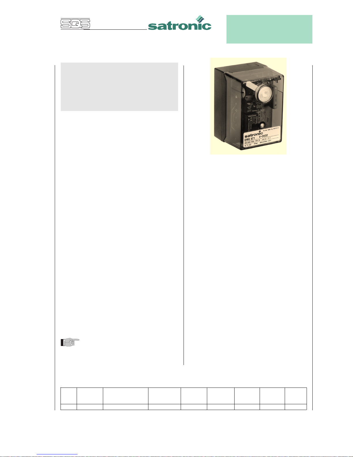
The burner control box DMG 971 controls and supervises
power burner for gas and dual fuel. The control box is
approved and certified according the relevant European
standards. The use on direct air heaters according DIN 4794
is also possible.
The microprocessor- based programming sequence ensures extremely stable timings independent of voltage variations, ambient temperature and/or switch-on cycles. The
built-in information system not only provides a continuous
monitoring of the actual state of the box (very helpful especially for monitoring the start-up phase) but also informs
about the cause of a possible lock out. The lock out cause
is stored in such a way that it can be retrieved even after a
power failure.
The control box is designed for maximum safety in case of
fluctuations in the voltage supply. If the mains voltage drops
below the permitted level, operation is interrupted and the
control box automatically prevents the start sequence from
being repeated. In this way, the safety of the system is not
put at risk by a drop in the mains voltage. This low-voltage
protection works not only during start-up but also permanently during operation.
CONSTRUCTIONAL FEATURES
Microprocessor, electronic components, output relais and
flame amplifier are placed on two printed circuit boards.
These plus the lockout- and reset circuit are well protected
inside a flame resistant, plug-in type plastic housing.
The reset switch for reset / remote lockout with its built-in
LED for displaying the information system plus the central
fixing screw are placed on top of the housing.
The wiring base S98 is equipped with spare- and
extraterminals and allows together with a variety of cable
entry points utmost flexibility of electrical wiring.
The DMG 971 is funstionally compatible to MMI 811 and
MMI 811.1
Please note: Is the DMG 971 to be used to
replace the MMI 811 or 811.1, care has to be
taken to make sure the air proving switch (LW) is
wired between terminals 4 and 7 and not like on
the MMI between 5 and 7.
DMG 971
Gas Burner Safety Control
For 2-stage forced draught and combi
oil/gas burners
Possible flame detectors:
- Ionisation probe
- Infrared flicker detector 1020
- UV flame sensor UVD 971
TECHNICAL DATA
Operating voltage 220 / 240 V (-15... +10%)
50 Hz ( ±5%)
Fuse rating 10 A fast, 6 A slow
Power consumption ca. 15 VA
Max. load per output
- term. 3 ignition trafo 1.5 A, cos ϕ 0.2
- term. 4 motor 2.0 A, cos ϕ 0.4
- term. 5 + 6 solenoid valves 1.0 A, cos ϕ 0.4
- term. B alarm indicator 1.0 A, cos ϕ 0.4
total load 5.0 A, cos ϕ 0.4
max. 10 A during 0.5 sec
Air proving switch 1 working contact 4 A, 230V
Stray light monitoring 5 sec
Sensitivity (operation) 1 µA
Min. required ion. current 1.5 µA
Sensitivity for stray light 0.4µA
Ionisation probe insulation Probe - earth
greater than 50 MΩ
stray capacity Probe - earth
less than 1000 pF
cable lenght < 3 m
Flame detectors
IRD 1020 side-on or end-on viewing
UVD 971 end-on viewing
Weight incl. Wiring base 190 g
Mounting position any
Protection class IP 40
Approved ambient parameter
for control and flame detector max. 95% at 30° C
- for operation -20° C... +60° C
- for storage -20° C... +80° C
Build-up of ice, penetration of water and condensing
water are inadmissible
Approvals according
to European standards EN 298 and EN 230, as
well as all other relevant
Directives and standards
Classified acc. to EN 298 FTLLXN
Timings (sec.)
0737.11-00-e/01/99
Model waiting time max. reaction time for supervised pre-ignition ignition time Stray light safety time delay
start air proving switch pre-purge time time total monitoring 2nd-stage
tlw tv1 tvz tz tf ts tv2
01 0 60 24 3 5 5 3 12.5
Page 2
2
APPLICATION FEATURES
1. Information system
The information system is microprocessor based and reports on all aspects of burner control box operation and
flame supervision. It informs continuously about the actual
programming sequence the unit is just performing. Besides
monitoring of the programming sequence it also allows to
identify errors during start-up of operation without any
additional testing devices. The automatically performed
diagnosis is a valuable tool which facilitates service/
maintenance work and therefore saves costs. The analyses
of the error cause can be done directly on stage or if not
possible afterwards as the lock out reason is stored in a nonvolatile lock out mode memory.
The information system communicates with the outside
world using a LED (the used Flash-Code is similar to the
Morse-Code). The messages are optically transmitted by a
appropriately flashing LED. Using an additional terminal
(optional), the messages can be recorded and displayed in
easy readable form.
1.1 Programming sequence display
The built-in microprocessor controls not only the programming sequence but the information system too. The
individual phases of the programming sequence are
displayed as Flash-Code.
The following messages can be distinguished:
Message Flash-Code
waiting for ❘ ❘ .
air proving switch
pre-purge ❘ ❘ ❘ .
tv1
pre-ignition ❘ ❘ ❘ ❘ .
tvz
safety time ❚ ❘ .
ts
delay 2nd stage ❚ ❘ ❘ .
tv2
running ❘ _
low mains voltage ❘ ❚ ❚ _
Description
❘ = short pulse
❚ = long pulse
. = short pause
_ = long pause
1.2 Lock-out diagnoses
In case of a failure the LED is permanently illuminated. Every
10 seconds the illumination is interrupted by a flash code,
which indicates the cause of the error. Therefore the following
sequence is performed which is repeated as long as the unit
is not reset.
Sequence:
illuminated phase dark phase Flash-Code dark phase
❘ ❚ ❚ ❚ ❚
for 10 sec for 0.6 sec for 1.2 sec
Error diagnosis
Error message Flash-Code Possible fault
lock out ❘ ❚ ❚ ❚ ❚ within lock out safety time
safety time no flame establishment
stray light ❘ ❘ ❚ ❚ ❚ stray light
during monitored phase,
detector may be faulty
air proving switch ❚ ❚ ❘ ❘ ❘ air proving switch
in closed position contact welded
air proving switch ❘ ❘ ❘ ❚ ❚ air proving switch does not
time-out close within specified time
air proving switch ❘ ❘ ❘ ❘ ❚ air proving switch opens
opened during start or operation
loss of flame ❚ ❚ ❚ ❚ ❘ loss of flame during
operation
Flash-Code for manual lock out
anual/external ❘ ❘ ❚ ❚ ❚ _ ❚ ❚ ❚ ❚ ❚
lock out
(see also 3. lock out and reset)
2. Flame detection
The following types of flame detectors are suitable:
– Ionisation probe, temperature resistant material, well
insulated (material and insulation same as for ignition
electrode).
– Infrared-flicker detector type IRD 1020 with mounting
flange M 93 or the UV solid state flame sensor UVD 971.
Flame detection using an ionisation probe is only possible
in conjunction with mains supplies which provides a neutral earth connection.
Connecting the IRD 1020 or UVD 971 the correct wiring
has to be observed.
2.1 Stray light monitoring
The stray light check is performed at the end of the prepurge time for thr duration as mentioned in the technical
datas.
DMG 971
Page 3

3
DMG 971
3. Lock out and reset
The unit can be reset or brought into lock out mode in two
different ways:
Internal
In the lock out case the unit can be reset by pushing the builtin button meaning a new start-up cycle is performed.
External
Instead of using the built-in lock out button the same
function can be achieved by using an external button which
connects terminal 1 with A (see also circuit and block
diagram).
If the pushputton (internal or external) is pressed during
normal operation or during the start sequence for more then
3 sec. and afterwards released, the control box will perform
a shutdown.
Please note
The unit can only be brought to lockout mode or
be reseted if power is applied to the unit.
4. Low-voltage protection
The mains voltage has to be more than 187 V
eff
in order to
allow the unit to perform a start-up.
The mains voltage is not only monitored in the start-up
phase but also permanently during operation. If the voltage
drops below < 160 V
eff
during start-up or run time the control
box goes into lock out mode. If the voltage rises again, the
control box performs automatically a start-up as soon as the
mains voltage is > 187 V
eff
.
5. Safety
The design and control sequence of the DMG 971 controls
will comply with the currently applicable standards and
regulations (see also TECHNICAL DATA).
6. Mounting and electrical wiring
Wiring base:
– 3 earth terminals with additional terminal for burner
earthing
– 3 neutral terminals with internal permanent connection to
neutral terminal 8
– 2 independant spare terminals (S1 and S2)
– extra terminals A, B and C are standard
– 2 slide-in plates and 2 easy knock out holes (PG11
thread) plus 2 knock out holes in the base bottom faciliate
the base wiring
The digital controls are ideally wiried on the new wiring
bases S98, which are equipped with (terminals B and C are
only for some special types of DMO or DMG) terminal A,.
which is used for the remote reset / remote lockout functions.
Please note
To assist trouble-free operation the main neutral
connection terminal in the wiring base must be
fully tightened. The terminal screws are already
in the undone position. To connect a wire to the
terminal, the screw only needs to be fastened.
General: The control box and detector probes should not be
subjected to excessive vibration.
Page 4

4
DMG 971
INSTALLATION INSTRUCTIONS AND MAINTENANCE
1. Important notes
– The controls must be installed by qualified personnel
only. The relevant national regulations have to be
observed.
– On commissioning the wiring has to be carefully check-
ed according the appropriate diagram, Incorrect wiring
can damage the unit and endanger the installation.
– The fuse rating has to ensure that the limits specified in
TECHNICAL DATA will not be exceeded. If these precautions are not observed, the effect of a short circuit can
cause severe damage to the control and installation.
– For safety reasons a minimum of one control shutdown
per 24 hours has to be observed.
– Disconnect the mains before the control box is plugged
in or out.
– The control box is a safety device and must not be
opened!
2. Function control
For safety reasons the flame detection system should be
tested on commissioning the installation as well as after a
service or longer shut-down.
a) Start-up with closed gas valve
– After lock out safety time is over the unit has to go into
lock out mode!
b) Normal start-up, when burner is running, close gas valve
– After loss of flame, the control box has to go into
lockout mode
c) Normal start-up, during pre-purge or operation, interrupt
the air proving switch
– The control box has to perform a lockout immediatly
d) Bridged air proving switch before start
– the fan motor switches on for approx. 2 - 3 secs,
followed by a lockout. After 10 secs., this quick
lockout is resetted by the control box and a second
start attempt follows (fan motor switches on for approx.
2 - 3 secs.). A standard lockout appears if the air
proving switch (LW) contact is still in it’s closed
position (e.g. welded contacts). Has the air proving
switch (LW) changed to it’s open position in the
meantime (e.g. by a run down motor), a normal start
sequence follows.
3. Fault finding
The built-in information system facilitates the trouble shooting in the case of problems occurring during start-up or
during operation.
A list of possible lock out messages can be found in
APPLICATION FEATURES chapter 1.2.
Please note:
The control box is locked in lock out mode and
the reasen for the lock out is displayed until
the control box is reset, either by an internal or
external reset (see also subject “3. Lock out
and reset").
Removing the control box from its wiring base or by
interrupting the supply line may not reset a lock out. Therefore, by applying power, the fan motor switches on for 2-3
secs. before the control box goes to lock out again and the
cause of the last lock out.
Error Possible fault
Burner not working - Thermostat circuit open
- Faulty electrical wiring
- mains voltage < 187 V
Fan motor/nozzle preheater - Control box has not been reset
starts for a short period of - Air proving switch not in open
time, control box goes to position
lock out
Control box locks out - Air proving switch has not during
pre-purge closed within 60 secs.
- Air proving switch has re-opened
Control box locks out - Air proving switch open
at the end of pre-purge - Flame signal
Burner starts, - Stray light on flame detector
flame not established, (IRD only)
lock out - No ignition or no fuel
Burner starts, - No or too low flame signal (flame
flame established, does not stick, bad insulation of
after safety time, the ionisation probe, bad conneclock out tion to frame ground)
- Insufficient light on IRD
- Sensitivity adjustment
too low on IRD
Page 5

5
CIRCUIT AND TIMING DIAGRAM DMG 971
BLOCK DIAGRAM DMG 971
term. 8
term. 2
term. 9
blue
black
brown
IRD 1020
UVD 971
IRD- OR UVD CONNECTION
DMG 971
HS Mains switch
GW Gas proving switch
ST Limit thermostat
RT Control thermostat
EV External reset and lock out button
IS Ionisation probe
(IRD 1010, UVD 971 see separate
diagram)
Z Ignition
M Burner motor
V1 Solenoid valve, 1st-stage
V2 Solenoid valve, 2nd-stage
LW Air proving switch
SA External lock out signal
tlw max. reaction time for air proving switch
tv1 Supervised pre-purge time
tvz Pre-ignition time
tz Ignition time total
ts Safety time
tv2 Delay 2nd-stage
M
Ph
N
HS
ST
GW
RT
EV
IS
Z
V1
V2
SA
LW
1
2
3
4
5
6
7
8
9
C
A
B
SV
tvz
tz
ts
tv2
tw
tv1
tlw
rv1
rs
2 6 57 43C 9B 8 1 A
rz
rv2
Flame
amplifier
Reset
µC
Reset and
lock out
Power
supply
monitoring
RZ
RV1 RV2
RS
Fault display
Information
system
EEPROM
Oscillator
µC
Watchdog
Mains
monitoring
Power
supply
max. 10A fast
6A low
RLK
Page 6

6
A Honeywell Company
Satronic AG
Brüelstrasse 7
Postfach 324
CH-8157 Dielsdorf
DMG 971 AND SOCKET
DMG 971
ORDERING INFORMATION
ITEM DESIGNATION ITEM NO.
Control box DMG 971 Mod. 01 0351001
Socket Wiring base S98 75310
Insert plate PG-Plate 70502
optional Cable entry plate 70501
Flame detector IRD 1020 end-on 16522
Flame detector IRD 1020 left 16523
Flame detector IRD 1020 right 16521
optional UVD 971 16722
Support for IRD Holder M93 for IRD 1020 59093
Support for UVD Holder M74 for UVD 59074
Connection cable Plug type, 3 core cable, 0.6 m with tag wire ends 7236001
The above ordering information refers to the standard version.
Special versions are also included in our product range. Specifications subject to change without notice
VARIATION IRD
right
HOLDER M 93 FOR IRD
left
axial
35
3
14
4.5
26
15.1
48
17
ø20.5
4
62,5
4,5
38,5
24
86
PG 11
60
24
30
30
44
M4
Earth
Reset button
57-60
25
35
30
Underside cable
entry ø16 mm
16
Slide-in plate
UVD 971 IRD 1020
29
50
UVD = 29
IRD = 44
21,8
ø13,5
UVD = 89
IRD = 104
29
21,8
 Loading...