

Page 1
GB
F
NL
I
E
445501
D GB F NL I E
TR CZ PL RUS H
Operating instructions
Pressure switches for air DL..A, DL..K
© 2018 Elster GmbH · Edition 05.18
Cert. version 05.18
Translation from the German
Contents
Contents
Pressure switches for air DL..A, DL..K......1
Contents ..............................1
Safety.................................1
Checking the usage .....................
Type code .............................2
Part designations ........................ 2
Type label.............................. 2
Installation ............................
Positive pressure measurement .............3
Negative pressure measurement . . . . . . . . . . . . 4
Differential pressure measurement ...........4
Wiring ................................4
Adjustment ............................5
Function check.........................5
Accessories ...........................5
Z-angle bracket .........................5
U-angle bracket .........................6
Standard coupler plug ....................6
Motor flange adapter . . . . . . . . . . . . . . . . . . . . . 6
Tube set ...............................6
Pilot lamp set, red or blue .................6
LED set, red/green....................... 7
External adjustment ......................7
Technical data .........................7
Designed lifetime ........................ 7
Logistics ..............................8
Certification ...........................8
Declaration of conformity ..................8
Contact ...............................8
DK S N P GR
➔ www.docuthek.com
Safety
Safety
Please read and keep in a safe place
Please read through these instructions
carefully before installing or operating. Following the
installation, pass the instructions on to the operator. This unit must be installed and commissioned
in accordance with the regulations and standards
in force. These instructions can also be found at
www.docuthek.com.
Explanation of symbols
• , 1 , , ... = Action
▷ = Instruction
Liability
We will not be held liable for damage resulting from
non-observance of the instructions and non-compliant use.
Safety instructions
Information that is relevant for safety is indicated in
the instructions as follows:
DANGER
Indicates potentially fatal situations.
WARNING
Indicates possible danger to life and limb.
CAUTION
Indicates possible material damage.
All interventions may only be carried out by qualified
gas technicians. Electrical interventions may only be
carried out by qualified electricians.
Conversion, spare parts
All technical changes are prohibited. Only use OEM
spare parts.
Changes to edition 11.17
The following chapters have been changed:
– Checking the usage
– Installation
– Certification
GB-1
Page 2
GB
F
NL
I
E
Checking the usage
DL 1,5 – A, DL K, DL 5 – 150A, DL 5 – 150K
For monitoring positive, negative or differential air or
flue gas pressures.
This function is only guaranteed when used within
the specified limits– see page7 (Technical data).
Any other use is considered as non-compliant.
Type code
Code Description
DL Pressure switch for air
1,5 – 150 Max. setting in mbar
K
A
T T-product
-
-
-4
-5
-6
-9
K
T
T
N
A External adjustment
W Z-angle bracket
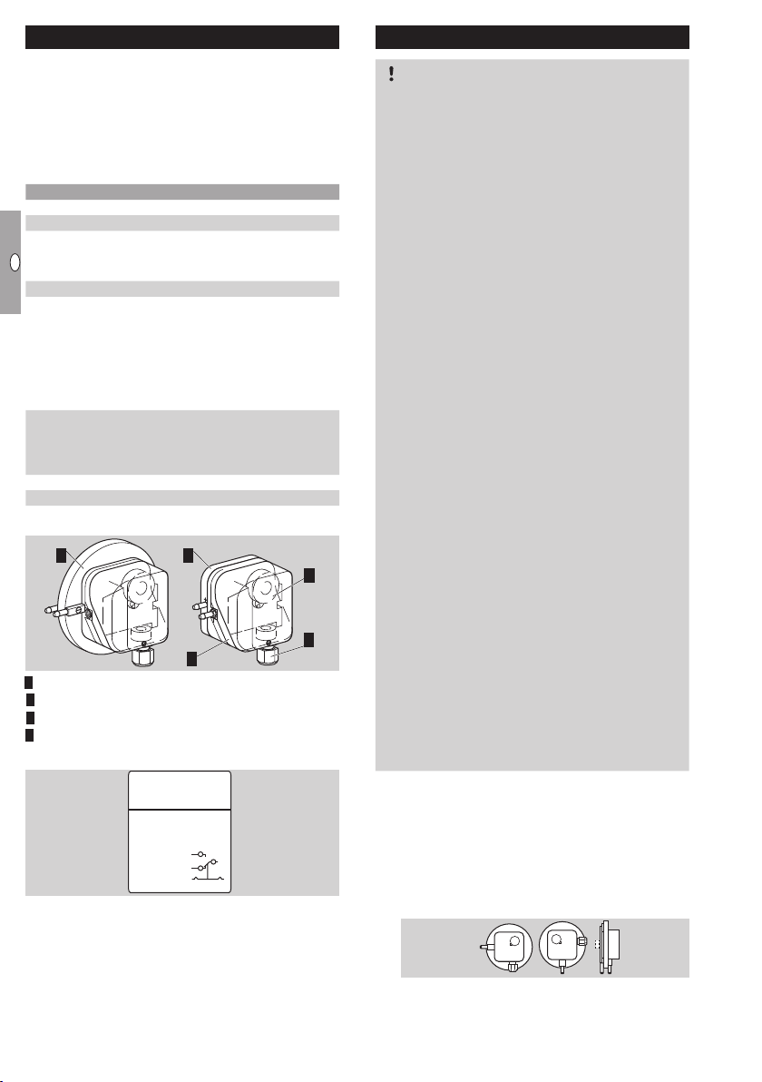
Part designations
1 Upper housing section with cover
Lower housing section
Hand wheel
4 M16 cable gland
Type label
Max. inlet pressure = withstand pressure, mains voltage, ambient temperature, enclosure: see type label.
With tube connection and hand wheel
Additionally with Rp¼connection
(optional: Rp
1
/8)
Electrical connection
via screw terminals, ½" NPT
via screw terminals
via screw terminals, IP 65
4-pin plug, without socket
4-pin plug, with socket
4-pin plug, with socket, IP 65
Red/green pilot LED for 24 V DC/AC
Blue pilot lamp for 230 V AC
Red/green pilot LED for 230 V AC
Blue pilot lamp for 120 V AC
22
3
4
1
D-49018 Osnabrück, Germany
DL
CE
2
3
1
Installation
CAUTION
Please observe the following to ensure that the DL
is not damaged during installation and operation:
– Dropping the device can cause permanent da-
mage. In this event, replace the entire device
and associated modules before use.
– Use approved sealing material only.
– Note the max. medium and ambient tempera-
tures, see page7 (Technical data).
– Condensation must not be allowed to get into
the housing (if possible, install pipework with an
ascending gradient). Otherwise, there is a risk of
icing of condensation at subzero temperatures,
the switching point shifting or corrosion in the
device which can lead to malfunctions.
– Protect the connections against dirt or moisture
in the medium to be measured or the surround-
ing air. If necessary, install a filter.
– In case of highly fluctuating pressures, install a
damping nozzle/restrictor orifice.
– When installing outdoors, place the DL in a
roofed area and protect from direct sunlight
(even IP65 version). To avoid condensation,
the cover with pressure equalization element
can be used on some types.
– In the case of an uneven mounting surface, se-
cure the pressure switch to the mounting plate
or air duct with only two screws on the same
side in order to avoid subjecting the pressure
switch to mechanical stress.
– When using silicone tubes, only use silicone
tubes which have been sufficiently cured. Va-
pours containing silicone can adversely affect
the functioning of electrical contacts.
– In the case of high humidity or aggressive gas
components, we recommend using a pressure
switch with gold contact due to its higher resist-
ance to corrosion. Closed-circuit current moni-
toring is recommended under difficult operating
conditions.
▷
The DL must not be in contact with masonry.
Minimum clearance 20mm.
▷ Ensure that there is sufficient installation space.
▷ Ensure unobstructed view of the hand wheel.
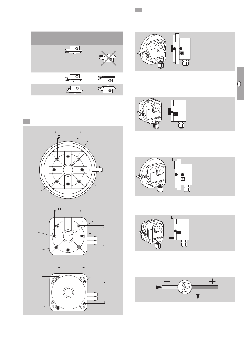
▷
Installation in the vertical or horizontal position, or
upside down, preferably with vertical diaphragm.
If installed in a vertical position, the switching
pointpS will correspond to the scale valueSK.
GB-2
Page 3
GB
F
NL
I
E
▷
50 (1.97")
30 (1.18")
20
(0.79")
25 (0.98")
45 (1.77")
5,2
(0.2")
11,3 (0.44")
7 (0.27")
7,5 (0.3")
10
(0.4")
40 (1.6")
59 (2.3")
ø 5,5 (0.22")
ø 6 (0.22")
ø 4,2 (0.17")
10 (0.39")
1 (0.04")
1 = Rp 1/4 (+),
2 = ø 4,75 x 1 mm (+)
3 = ø 4,75 x 1 mm (-)
(4 = Rp
1
/8 (-),
1
/8" NPT (-))
1
(4)
2
3
(1/4" NPT (+))
1 = Rp 1/4 (+),
2 = ø 4,75 x 1 mm (+)
3 = ø 4,75 x 1 mm (-)
(4 = Rp
1
/8 (-),
1
/8" NPT (-))
1 = Rp
1
/4 (+),
2 = ø 4,75 x 1 mm (+)
3 = ø 4,75 x 1 mm (-)
(4 = Rp
1
/8 (-),
1
/8" NPT (-))
1
(4)
2
3
1
Test
2
3(4)
(1/4" NPT (+))
(
1
/4" NPT (+))
1 = Rp 1/4 (+),
2 = ø 4,75 x 1 mm (+)
3 = ø 4,75 x 1 mm (-)
(4 = Rp
1
/8 (-),
1
/8" NPT (-))
1 = Rp
1
/4 (+),
2 = ø 4,75 x 1 mm (+)
3 = ø 4,75 x 1 mm (-)
(4 = Rp
1
/8 (-),
1
/8" NPT (-))
2 = ø 4,75 x 1 mm (+)
3 = ø 4,75 x 1 mm (-)
)
1
(4)
2
3
1
2
3
Test
2
3(4)
(1/4" NPT (+))
(
1
/4" NPT (+))
If installed in another position, the switching
pointpS will change and no longer correspond
to the set scale valueSK. Switching pointpS
must be checked.
SK + 0.18 mbar
[+ 0.071 "WC]
SK - 0.18 mbar
[- 0.071 "WC]
DL 1,5A
DL 3K,
DL 3A
DL 5 – 150A,
DL 5 – 150K
▷
For 1 mm thick mounting plates, use self-tapping
screws for plastic:
DL..A, DL 3K: Ø 3.5 x 8 mm or Ø 4 x 8 mm.
DL 5 – 150K: Ø3.5 x 16 mm.
1 Fit the DL.
DL 1,5A
DL 3A
DL 3K
e.g. SK = -0.5:
ps = -0.5 + 0.18
ps = -0.32 mbar
49,5 (1.9")
44,5 (1.7")
DL..A: Rp ¼
(DL..AT: ¼" NPT)
ø 6,1 (ø 0.24")
Connect the pressure line.
▷
DL..A: upon delivery, port 2 is closed off by a
rubber cap.
DL 1,5A, DL A
1 = Rp 1/4 (+),
2
3
1
(4)
(1/4" NPT (+))
2 = ø 4,75 x 1 mm (+)
3 = ø 4,75 x 1 mm (-)
1
(4 = Rp
/8 (-),
1
/8" NPT (-))
▷ Positive pressure: port 1 or 2
▷ Negative pressure: port 3
▷ Special version DL 3A – 3Z: port 4
DL 5 – 150A
Test
2
1
3(4)
1
/4 (+),
1 = Rp
1
/4" NPT (+))
(
2 = ø 4,75 x 1 mm (+)
3 = ø 4,75 x 1 mm (-)
1
(4 = Rp
/8 (-),
1
/8" NPT (-))
▷ Positive pressure: port 1 or 2
▷
Negative pressure: port 3; after unscrewing
port3 also port4
DL K
2
3,5 × 8
(0.14" × 0.3")
DL 5–150A
2,7 × 8
(0.11" × 0.3")
3,5 × 8
(0.14" × 0.3")
DL 5–150K
64 (2.5")
49,5 (1.9")
54,5 (2.1")
2,7 × 8
(0.11" × 0.3")
DL..A: Rp ¼
(DL..AT: ¼" NPT)
44,5 (1.7")
2,7 × 16
(0.11" × 0.6")
45 (1.8")
▷ Positive pressure: port 2
▷ Negative pressure: port 3
DL 5 – 150K
2
(5)
▷ Positive pressure: port 2
▷ Negative pressure: port 3
▷ Optional test point for positive pressure: port5
Positive pressure measurement
▷ 1 or 2 = positive pressure port(+).
▷ If port2 is used, close off port1.
3 or 4 = remains open to ventilate the upper
▷
diaphragm chamber.
GB-3
3 = ø 4,75 x 1 mm (-)
3
2 = ø 4,75 x 1 mm (+)
3
3 = ø 4,75 x 1 mm (-)
(5 = ø 4,75 x 1 mm (+)
2 = ø 4,75 x 1 mm (+)
Page 4

GB
F
NL
I
E
Negative pressure measurement
▷ 3 or 4 = negative pressure port(-).
▷
1 or 2 = remains open to ventilate the upper
diaphragm chamber.
Differential pressure measurement
▷ 1 or 2 = port for the higher positive pressure or
lower negative pressure(+).
▷ 3 or 4 = port for the lower positive pressure or
higher negative pressure(-).
Seal the ports that are not in use.
1 Disconnect the system from the electrical power
supply.
3 42
6 75
M16 x 1,5:
ø 4–10 mm
▷
Contacts and close when subject to increasing pressure. Contacts 1 and close when subject to falling pressure. With the NO contact, the
NC contact is omitted.
NO
L1
3
COM
2
NC
1
NO
1
2
NC
3
COM
Wiring
▷
If the DL..G (DL..TG) has switched a voltage
>24V (>30V) and a current >0.1A at cosφ=1
or >0.05A at cosφ=0.6 once, the gold plating
on the contacts will have been burnt through. It
can then only be operated at this power rating
or higher power rating.
CAUTION
To ensure that the DL is not damaged during opera-
tion, note the switching capacity, see page 7
(Technical data).
▷ In the case of low switching capacities, such as
24V, 8mA, for example, we recommend using
an RCmodule (22 Ω, 1μF) in air containing
silicone or oil.
C = 1 µF R = 22 Ω
NO
2
NC
1
COM
3
DL 1,5A
▷
The connection depends on the positive or nega-
tive adjusting range.
-
0
,
5
-
0
r
,
a
2
b
5
m
5
,
1
0
–
,
0
5
,
0
-
DL 1,5A
▷
Negative adjusting range 0 to -0.5 mbar: con-
0
,
2
5
0
,
5
5
,
1
1
m
b
a
r
5
=
2
,
1
0
1
0
P
a
0
,
1
5
7
,
0
tacts 3 and 1 close when subject to increasing
negative pressure. Contacts 2 and 3 close when
subject to falling negative pressure.
NO
NC
2
1
µ
COM
3
GB-4
Page 5

GB
F
NL
I
E
Adjustment
NO
2
NC
1
COM
3
COM
3
NC
1
NO
2
▷
The switching point is adjustable via hand wheel.
1 Disconnect the system from the electrical power
supply.
Detach the housing cover, see page7 (Tech-
nical data).
Connect an ohmmeter.
NO
1
2
NC
3
COM
NO
COM
2
NC
3
1
4 Set the switching point using the hand wheel.
5 Connect a pressure gauge.
0
▷
Deviation from the switching point during testing
pursuant to EN1854:
Air pressure switches:
DL 5 – 150A,
DL 5 – 150K
DL 1,5A
DL 3A, DL 3K
▷
If the DL does not trip at the desired switch-
Deviation
± 15%
± 15% or ± 6 Pa
± 15% or ± 6 Pa
ing point, correct the adjusting range using the
hand wheel. Relieve the pressure and repeat
the process.
Function check
▷ We recommend a function check once a year.
▷ Press the test key during operation– the pres-
sure switch switches.
1 cm = 1 mbar
TEST
+
6 Apply pressure. In doing so, monitor the switch-
ing point on the ohmmeter and the pressure
gauge.
▷ Max. inlet pressure = withstand pressure
Max.
inlet
pressure
mbar
Switching
differential**
mbar
Type
Adjusting
range*
mbar
min. max. min. max.
DL 1,5A -0.5 1.5 50 0.1 0.16
▷ In case of differential pressure, press both keys
simultaneously.
TEST
TEST
+
–
DL 3A, ..3K 0.2 3 50 0.1 0.16
DL 3AT, ..3KT 0.3 3 150 0.1 0.16
DL 5A, ..5K 0.4 6 300 0.2 0.3
DL 5AT, ..5KT 0.5 5 300 0.2 0.3
DL 10A, ..10K,
..10AT, ..10KT
1 10 300 0.25 0.4
DL 30A, ..30K 2.5 30 300 0.35 0.9
DL 50A, ..50K,
..50AT, ..50KT
DL 150A,
..150K
Type
2.5 50 300 0.8 1.5
30 150 300 3 5
Adjusting
range*
"WC
min. max. min. max.
Max.
inlet
pressure
"WC
Switching
differential**
"WC
DL 3AT, ..3KT 0.12 1.2 58.5 0.04 0.06
DL 5AT, ..5KT 0.2 2 117 0.08 0.12
DL 10AT,
..10KT
DL 50AT,
..50KT
* Adjusting tolerance ±15% of the scale value, but
min. ±4Pa
0.4 4 117 0.1 0.16
1 20 117 0.3 0.6
Accessories
Z-angle bracket
DL 5 – 150K: Order No.: 74916158
DL 3 – 150A, DL 3K: Order No.: 74913661
7,5 (0.3")
1 (0.04")
10 (0.39")
40 (1.6")
59 (2.3")
ø 4,2 (0.17")
ø 5,5 (0.22")
ø 6 (0.22")
7 (0.27")
11,3 (0.44")
** Mean switching differential at min. and max. setting
GB-5
Page 6

GB
F
NL
I
E
U-angle bracket
47,5 (1.87"
2 31
DL 1,5 – 150A, DL 3 – 150K: Order No.: 74916185
Tube set
To be used with air only.
75 (2.95")
20
(0.79")
M4 x 12
50 (1.97")
30 (1.18")
20
(0.79")
45 (1.77")
25 (0.98")
6 (0.24")
16
24 (0.94")
43
(1.69")
-0,3
64 (2.52")
Standard coupler plug
(0.63")
)
40 (1.57")
M4 x 10
5,2
(0.2")
+0,1
(0.17")
4,20
10
(0.4")
39 (1.53")
Order No.: 74912952
Order No.: 74919272
Pilot lamp set, red or blue
DL..T, DL..N
Pilot lamp, red:
110/120 V AC, I = 1.2 mA, Order No.: 74920430;
220/250 V AC, I = 0.6 mA, Order No.: 74920429.
Pilot lamp, blue:
110/120 V AC, I = 1.2 mA, Order No.: 74916121;
220/250 V AC, I = 0.6 mA, Order No.: 74916122.
4
N
3
COM
NO
L1
2
NC
1
NO
2
NC
NO
1
3
COM
N
Order No.: 74916159
Motor flange adapter
Set including retaining screws
DL..A, DL 3 – 5K: Order No.: 74916157,
DL 5 – 150K: Order No.: 74916156.
GB-6
NO
NC
L1
3
COM
2
1
NC
N
NO
1
2
NC
3
COM
N
Page 7

GB
F
NL
I
E
LED set, red/green
DL..K2, DL..T2
24 V DC, I = 16 mA; 24 V AC, I = 8 mA,
Order No.: 74921089;
230 V AC, I = 0.6 mA, Order No.: 74923275.
2 31
4
NO
2
+
3 COM
1 NC
1
2
NC
NO
–
3
COM
N
External adjustment
In order to set the switching pressure from the outside, the cover for external adjustment (6mm Allen
key) for DL..A, DL5 – 150K can be retrofitted.
Order No.: 74916155
2 31
Technical data
Gas type: air or flue gas, no flammable gases, no
aggressive gases.
Max. inlet pressure = withstand pressure: see type
label or page 5 (Adjustment).
Micro switch to EN 61058-1.
Switching capacity:
DL..: 24 V (min. 0.05 A) to 250 V AC
(max. 5 A, at cos φ 0.6 = 1 A),
max. 6 A, temporarily (<1 s) 20A.
DL..G: 5 V (min. 0.01 A) to 250 V AC
(max. 5 A, at cos φ 0.6 = 1 A),
5 V (min. 0.01 A) to 48 V DC (max.1A),
DL..T: 30 – 240 V AC, 50/60 Hz,
5 A resistive or
0.5 A inductive (cos φ= 0.6),
DL..TG: < 30 V AC/DC,
0.1 A resistive or
0.05 A inductive (cos φ= 0.6).
Contact gap < 3 mm (μ).
Safety class II to VDE 0106-1.
Max. medium and ambient temperatures:
DL: -20 to +80°C (-4 to +176°F),
DL..T: -40 to +60°C (-40 to +140°F).
Long-term use in the upper ambient temperature
range accelerates the ageing of the elastomer materials and reduces the service life (please contact
manufacturer).
Storage temperature:
-20 to +40°C (-4 to +104°F).
Diaphragm pressure switch, NBR, silicone-free.
Housing: glass fibre reinforced PBT plastic with
low gas release.
Enclosure to IEC 60529: IP54, IP65.
Line entrance: M16 x 1.5 (1/2" NPT conduit),
clamping range: diameters of 4 to 10mm.
Type of connection: screw terminals.
Max. tightening torque, see Technical Information
bulletin DL (D, GB, F) – www.docuthek.com.
Weight: DL..A: 190g (6.7oz), DL..K: 220 g
(7.8oz).
Designed lifetime
This information on the designed lifetime is based on
using the product in accordance with these operating
instructions. Once the designed lifetime has been
reached, safety-relevant products must be replaced.
Designed lifetime (based on date of manufacture) in
accordance with EN13611, EN1854 for pressure
switches: 10 years.
You can find further explanations in the applicable
rules and regulations and on the afecor website
(www.afecor.org).
This procedure applies to heating systems. For
thermoprocessing equipment, observe local regulations.
GB-7
Page 8

GB
F
NL
I
E
Logistics
AGA
Transport
Protect the unit from external forces (blows, shocks,
vibration). On receipt of the product, check that the
delivery is complete, see page2 (Part designations). Report any transport damage immediately.
Storage
Store the product in a dry and clean place.
Storage temperature: see page7 (Technical data).
Storage time: 6months before using for the first
time. If stored for longer than this, the overall service
life will be reduced by the corresponding amount of
extra storage time.
Packaging
The packaging material is to be disposed of in ac-
cordance with local regulations.
Disposal
Components are to be disposed of separately in
accordance with local regulations.
The production is subject to the surveillance proce-
dure pursuant to Regulation (EU) 2016/426 AnnexIII
paragraph 3.
Elster GmbH
Scan of the Declaration of conformity (D, GB) – see
www.docuthek.com
FM approval
Factory Mutual Research Class: 3510 Flow and pressure safety switches.
Designed for applications pursuant to NFPA 85 and
NFPA 86.
UL approval
Certification
Declaration of conformity
We, the manufacturer, hereby declare that the product DL with product ID No. CE-0085AP0466 complies with the requirements of the listed Directives
and Standards.
Directives:
– 2014/30/EU – EMC
– 2014/35/EU – LVD
Regulation:
– (EU) 2016/426 – GAR
Standards:
– EN 13611:2015+AC:2016
– EN 1854:2010
The relevant product corresponds to the tested type
sample.
Contact
Contact
UL 353 Limit control
AGA approval
Australian Gas Association, Approval No.: 5484
Eurasian Customs Union
The product DL meets the technical specifications
of the Eurasian Customs Union.
RoHS compliant
Directive on the restriction of the use of
hazardous substances (RoHS) in China
Scan of the Disclosure Table China RoHS2 – see
certificates at www.docuthek.com
If you have any technical questions, please contact
your local branch office/agent. The addresses are
available on the Internet or from ElsterGmbH.
We reserve the right to make technical modifications
in the interests of progress.
Strotheweg 1, D-49504 Lotte (Büren)
Elster GmbH
Tel. +49 541 1214-0
Fax +49 541 1214-370
hts.lotte@honeywell.com, www.kromschroeder.com
GB-8
 Loading...