

Page 1

73022387
Revision g (2019-01)
From software version 1.12
Data Logger
DL230
Operating Instructions
Page 2

Exclusion of liability
The information contained in this document is the property of Honeywell. The
following information may only be used for its intended purpose. This document
or its contents must not be copied, published or made accessible to a third party in full or in part without the express consent of Elster GmbH.
All specifications and descriptions in these operating instructions have been
compiled following careful testing. In spite of this, errors cannot be completely
ruled out. Honeywell can therefore not provide any guarantee that the content
is complete or correct. The instructions must also not be seen as a warranty of
product features. Furthermore, features are also described here, which are only
available as an option.
Honeywell cannot accept liability in any case for direct, special or consequential
damage suffered by third parties. The information and specifications in this
document may be amended without notice.
In view of extended product liability, the listed data and material properties should only be regarded as reference values and must always be
checked for each individual case and corrected if necessary. This is especially the case when safety aspects are affected.
Further support is available from your local branch office or agent. The address
is available on the Internet or from Honeywell.
This manual or parts of it may only be disclosed or copied with written consent
from Honeywell.
If the product described here is improperly handled, repaired or changed by
unauthorized persons or if spare parts other than those supplied by Honeywell
are used, our warranty will be rendered void.
All rights reserved.
Copyright © 2019 Elster GmbH, D-55252 Mainz-Kastel. All rights reserved.
Mainz-Kastel, January 2019
Page 3

3
Contents
1 General ................................................................................................. 7
1.1 Information about this manual ....................................................... 7
1.2 Warranty provisions ....................................................................... 7
1.3 Customer service .......................................................................... 7
1.3.1 Customer service and repairs ..............................................................8
1.3.2 Electronic hotline ..................................................................................8
1.4 Meaning of symbols ...................................................................... 8
1.4.1 Safety instructions ................................................................................8
1.4.2 Tips and recommendations ..................................................................9
1.5 Limitation of liability ....................................................................... 9
1.6 Copyright protection .................................................................... 10
1.7 Scope of delivery ......................................................................... 10
1.8 Spare parts and accessories ....................................................... 11
1.9 Storage ........................................................................................ 12
2 Safety ................................................................................................. 13
2.1 General ........................................................................................ 13
2.2 Intended use ................................................................................ 14
2.3 Personnel .................................................................................... 15
2.4 Personal protective equipment .................................................... 16
2.5 Specific risks ............................................................................... 17
2.6 Environmental protection............................................................. 18
2.7 Operator's responsibility .............................................................. 18
3 Technical data ................................................................................... 19
3.1 General data ................................................................................ 19
3.2 Power supply for DL230 without integrated power supply unit ... 20
3.2.1 Battery power supply for the basic device .......................................... 20
3.2.2 Battery power supply for the integrated modem ................................. 20
3.2.3 Battery power supply for the modem module ..................................... 21
3.3 Power supply for the DL230 with integrated power supply unit .. 21
3.3.1 External power supply ........................................................................ 21
3.3.2 Battery power supply for the DL230 during power failure ................... 21
3.3.3 Buffer batteries for the integrated modem during power failure ......... 21
3.3.4 Buffer battery for the modem module during power failure ................ 22
3.4 Power supply for the DL230 with Power over Ethernet (PoE) .... 22
3.5 Digital inputs ................................................................................ 22
3.5.1 Pulse and signal inputs ...................................................................... 23
3.5.2 Encoder inputs ................................................................................... 24
3.6 Digital outputs .............................................................................. 24
3.6.1 Nominal data ...................................................................................... 24
3.7 Interfaces ..................................................................................... 25
3.7.1 Serial optical interface ........................................................................ 25
Page 4

4
3.7.2 Integrated modem .............................................................................. 25
3.7.3 Serial electrical interface (optional) .................................................... 25
3.7.4 GSM / GPRS modem module ............................................................ 26
3.7.5 Ethernet Module (optional) ................................................................. 27
3.8 Measurement conditions ............................................................. 27
3.8.1 Environment ....................................................................................... 27
3.9 Labelling ...................................................................................... 28
3.9.1 Designation Data Logger ................................................................... 28
3.9.2 ATEX marking .................................................................................... 29
3.9.3 Device software Identification ............................................................ 30
4 Construction and Function .............................................................. 31
4.1 External view ............................................................................... 31
4.2 Internal view ................................................................................ 32
4.3 Short description .......................................................................... 32
4.4 Connections ................................................................................. 33
5 Assembly, Connection and Putting into Operation ....................... 34
5.1 Assembly ..................................................................................... 34
5.1.1 Assembly on a pipeline ...................................................................... 35
5.1.2 Assembly on a wall ............................................................................ 36
5.2 Connection .................................................................................. 37
5.2.1 Connecting meters ............................................................................. 38
5.2.2 Sealing the input terminals ................................................................. 39
5.2.3 Connecting the power supply ............................................................. 39
5.2.4 Connect outputs of the DL230 ........................................................... 40
5.3 Putting into operation................................................................... 43
5.3.1 Configuration of measurement parameters ........................................ 43
5.3.2 Sealing ............................................................................................... 49
5.3.3 Closing the housing ........................................................................... 50
5.3.4 Verifying assembly and connection ................................................... 51
5.3.5 Data transfer ...................................................................................... 51
6 Operation ........................................................................................... 52
6.1 Safety........................................................................................... 52
6.1.1 Personal protective equipment .......................................................... 52
6.2 Operating personnel .................................................................... 52
6.2.1 Instructed personnel .......................................................................... 52
6.2.2 Qualified personnel ............................................................................ 52
6.2.3 Calibration officer ............................................................................... 53
6.3 Basic principles ............................................................................ 54
6.3.1 Display ............................................................................................... 55
6.3.2 Button functions ................................................................................. 56
6.3.3 Data recall, display navigation ........................................................... 57
6.3.4 Meaning of status symbols ................................................................ 58
6.3.5 Error messages when entering values ............................................... 59
6.3.6 Access rights ..................................................................................... 60
Page 5

5
6.4 Data register content ................................................................... 62
6.4.1 Access rights ...................................................................................... 62
6.4.2 "Main" register (main display)............................................................. 63
6.4.3 "Cust." Register (Customer) ............................................................... 64
6.4.4 "Admin" Register (Administrator)........................................................ 66
6.4.5 "Serv." register (Service) .................................................................... 67
6.4.6 "Ctrl." register (control) ....................................................................... 68
6.5 Use as high-flow display device .................................................. 70
6.6 Use as flow-recording device ..................................................... 71
6.6.1 Search function for checking archive entries ...................................... 72
7 Maintenance ...................................................................................... 73
7.1 Safety .......................................................................................... 73
7.1.1 Personnel ........................................................................................... 75
7.1.2 Personal protective equipment ........................................................... 75
7.1.3 Environmental protection ................................................................... 75
7.2 Testing and changing device batteries ........................................ 76
7.2.1 Changing and connecting device batteries ........................................ 76
7.2.2 Entering the battery capacity .............................................................. 79
7.2.3 Display remaining battery power ........................................................ 80
7.3 Changing and testing modem batteries ...................................... 80
7.3.1 Changing and connecting modem batteries ....................................... 80
7.3.2 Display modem battery voltage .......................................................... 84
7.4 Changing the fuse of the power supply unit ................................ 84
8 Faults .................................................................................................. 87
8.1 Safety .......................................................................................... 87
8.1.1 Personnel ........................................................................................... 88
8.1.2 Personal protective equipment ........................................................... 88
8.1.3 Improper elimination of faults ............................................................. 88
8.1.4 Behaviour in the event of faults .......................................................... 89
8.2 Fault and other status messages ................................................ 89
9 Appendix ............................................................................................ 93
9.1 List of spare parts and accessories ............................................. 93
9.1.1 Fastening elements ............................................................................ 93
9.1.2 Small parts and miscellaneous .......................................................... 93
9.1.3 Documentation ................................................................................... 94
9.2 Connection, Replacement and Retrofit of Components .............. 94
9.3 EC Declaration of Conformity ...................................................... 98
9.4 ATEX Type Examination Certificate ............................................ 99
9.4.1 Associated apparatus for Zone 0/1 .................................................... 99
Page 6

Page 7

General 7
The data and material properties indicated serve as reference values. These must be verified on a case-by-case basis and adjusted as necessary.
The application manual is available for you for the
commissioning of the various communication and device
applications.
1 General
1.1 Information about this manual
This manual allows for safe and efficient use of the device.
Compliance with all safety information and instructions for use contained in
this operating manual is a prerequisite for safe working processes and
proper use of the device. Furthermore, the valid guidelines, standards, local
accident prevention regulations, and general safety regulations must be
complied with for the respective area of application of the device.
This manual forms a constituent part of the product and must be stored
within the immediate vicinity of the device and be accessible to installation,
service, maintenance, and cleaning personnel at all times. The graphic illustrations used in this manual serve as a visual representation of the described processes and are therefore not necessarily to scale and may deviate from the actual design of the device.
1.2 Warranty provisions
The current warranty provisions can be found in the general terms and
conditions online under:
http://www.elster-instromet.com/en/general-terms-of-business
1.3 Customer service
Our customer service team is responsible for providing technical
information and repairs. Our employees are constantly striving to acquire
new information and gain experience and these are both valuable sources
for improving our products.
Page 8
8 General
1.3.1 Customer service and repairs
– Tel. +49 (0) 61 34 / 605-0
– Fax +49 (0) 61 34 / 605-390
– E-mail: Katinka.Fiedler@Honeywell.com
1.3.2 Electronic hotline
In the event of faults, you can also contact the electronic
hotline.
– Tel. +49 (0) 6134 / 605-123
– http://www.elster-instromet.com/en/support
– E-mail: ElsterSupport@Honeywell.com
1.4 Meaning of symbols
1.4.1 Safety instructions
In this manual, safety information is denoted by the use of symbols. The
safety information is introduced by signal words, which identify the level of
risk.
This safety information must be complied with and care should be taken to
prevent accidents, personal injury, and material damage.
DANGER!
... indicates an imminently dangerous situation which, if not
avoided, could lead to death or serious injury.
WARNING!
... indicates a potentially dangerous situation which, if not
avoided, could lead to death or serious injury.
CAUTION!
... indicates a potentially dangerous situation which, if not
avoided, may lead to minor or slight injuries.
… indicates dangers resulting from electrical current. A
non-compliance of the safety information poses a risk of serious or life-threatening injuries.
Page 9

General 9
CAUTION!
... indicates a potentially dangerous situation which, if not
avoided, could lead to material damage.
1.4.2 Tips and recommendations
… provides useful tips and recommendations as well as
information for ensuring efficient and smooth operations.
1.5 Limitation of liability
All of the information contained in this manual has been compiled under
consideration of valid standards and regulations, the latest technological
developments, and our many years of experience and expertise. The
manufacturer shall accept no liability for damages resulting from:
– Non-compliance of the manual
– Improper use
– Deployment of unqualified personnel
– Unauthorized modifications
– Technical changes
– Use of unauthorized spare parts
The actual scope of delivery may deviate from the information and graphics
presented herein due to special designs, the selection of additional ordering options, or the latest technological developments.
The obligations stipulated in the delivery contract, the general terms and
conditions and delivery conditions of the manufacturer, and the statutory
provisions valid at the time of signing the contract, shall apply.
This manual should be read carefully before commencing all
works on and with the device, particularly before putting the
device into operation! The manufacturer shall not assume
any liability for damage and errors caused by failing to
observe these instructions.
We reserve the right to make technical changes within the scope of improving usability and further development.
Page 10

10 General
1.6 Copyright protection
This manual is copyright-protected and is intended for internal use only. A
transfer of this manual to third parties, a reproduction of any kind, whether
partially or fully, and the use and/or disclosure of its content, are not
permitted without written consent from the manufacturer, except for internal
purposes. Contraventions to this provision shall result in damage
compensation. We reserve the right to assert further claims.
1.7 Scope of delivery
The scope of delivery for the DL230 includes:
– Data Logger DL230
– Dispatch list
– Design data sheet
– Manual
– Bag of accessories
Page 11

General 11
1.8 Spare parts and accessories
WARNING!
Incorrect use of spare parts and accessories may present a risk to safety!
False or incorrect use of spare parts and accessories may
impair safety and lead to damage, malfunctions, or total
failures.
Therefore:
– Only use original spare parts and accessories produced
by the manufacturer.
– The manufacturer should always be contacted in the
event of uncertainty.
A list of spare parts and accessories can be found in the appendix. Spare
parts and accessories can be ordered from an authorized retailer or from
our customer service team directly.
The free "enSuite" program also belongs to the accessories for the DL230
and is available under www.elster-instromet.com. This can be used to program the DL230 data logger via its data interfaces to perform advanced
applications.
The DL230 can be supplied as a calibrated and non-calibrated device and
is also available in different models.
Further details can be found under www.elster-instromet.com and in the
"Assembly, Connection and Putting into Operation" chapter.
Page 12
12 General
1.9 Storage
CAUTION!
Exceeding or falling below the valid temperature range
for the batteries may impair performance.
If the valid temperature range of the batteries during storage of the device is exceeded or fallen below, the performance of the batteries may be impaired.
Therefore:
– For long periods of storage, please ensure that the valid
temperature range for the fitted batteries does not fall
below -25 °C or exceed +55 °C.
CAUTION!
Material damage caused by the formation of
condensation.
Fluctuations in temperature during storage may cause condensation to form. This may lead to subsequent malfunctions of the device.
Therefore:
– After storage or transport in cold weather conditions or
after having been exposed to strong temperature
fluctuations, the device should slowly be adjusted to the
room temperature before being put into operation.
– If condensation has formed, wait at least 12 hours be-
fore putting the device into operation.
If the power supply to the device is cut off during storage
due to disconnecting the batteries then the date and time
must be reset.
The following rules apply for storage:
– The relative humidity should be a maximum of 93%.
– Do not store packages in the open air.
– The storage temperature should not fall below -25 °C and should not
exceed +60 °C.
– Avoid mechanical vibrations during storage of the device.
Page 13
Safety 13
2 Safety
This chapter gives an overview of all of the most important safety aspects
in order to best protect personnel and to ensure a safe and smooth
operation of the device. A non-compliance with the safety information and
instructions for use specified in this manual could result in serious damage.
2.1 General
The DL230 is an intrinsically safe device as per the ATEX Product Directive
94/9/EC and the ATEX Operating Directive 1999/92/EC EN, and is suitable
for operation within the following explosive gas atmospheres:
– DL230 with integrated power supply unit and integrated modem:
Associated apparatus for zones 0 and 1
– DL230 with integrated power supply unit and integrated modem:
Zone 2 for gases in temperature class T4
DANGER!
Using incorrect batteries presents a risk of explosion!
Only use batteries prescribed by Elster in accordance with
Chapter 9.1.2.
When connecting and operating the DL230 in explosive gas
atmospheres, the corresponding standards must be
observed:
DIN EN 60079-0
DIN EN 60079-14
The device may only be used as associated apparatus for
zone 0 and 1 or inside zone 2, if installation has been
carried out according to the separate requirements
stipulated under DIN EN 60079-14 and the operating
conditions (see "Technical Data" chapter) as well as the
connection conditions (see "Assembly, Connection and
Putting into Operation" chapter).
Page 14

14 Safety
The device may be dangerous if unqualified personnel use it incorrectly or
do not use it according to its intended purpose.
– All of those persons, who are charged performing works on or with the
device, must have read and understood the manual before commencing such works. This shall also apply if the person in question has already worked with the same or a similar device or has been trained by
the manufacturer.
– Being familiar with the content of the manual is a necessary condition
for protecting personnel against risks, preventing errors from occurring,
and therefore ensuring a safe and smooth operation of the device.
– In order to avoid risks and to ensure optimal performance of the device,
neither modifications nor changes should be carried out without express consent from the manufacturer.
– All operating instructions should be kept in a clearly legible condition on
the device. Damaged or illegible instructions should be replaced immediately.
– The setting values and value ranges specified in this manual should be
complied with.
2.2 Intended use
This device is solely designed and constructed for the intended use described below.
Data logger DL230 is provided as a compact device which can be calibrated for measuring and saving counter pulses, meter readings or level
changes for various types of energy.
Intended use also refers to compliance with all of the information contained
in this manual. Any use beyond the intended use and/or other types of use,
shall be considered as misuse and can result in dangerous situations. The
manufacturer shall not be held liable for any claims for damages resulting
from misuse of this device.
WARNING!
Danger resulting from misuse.
Misuse of the device may lead to dangerous situations.
Therefore:
– Only use the device according to its intended use.
– Do not use the device to regulate the gas flow or other
variables affecting the gas volume in the entire system.
Page 15

Safety 15
2.3 Personnel
WARNING!
Risk of injury to unqualified personnel.
Improper use of the device may lead to significant personal
injury or material damage.
Therefore:
– All works should solely be carried out by qualified per-
sonnel.
The following qualifications are used in the manual to denote different
areas of responsibility:
– Instructed personnel
will be informed of the tasks assigned to them and possible risks resulting from inappropriate behaviour, in a training session provided by the
operator.
– Qualified personnel
on the basis of their specialist training, knowledge and experience, as
well as their awareness of the relevant statutory provisions, are in a
position to perform their assigned tasks on the device and are able to
independently identify and prevent possible risks.
– Gas specialists
who, on the basis of their specialist training, knowledge and experience, as well as their awareness of the relevant standards and regulations, are in a position to perform works on gas-handling equipment
and to independently identify possible risks. The gas specialist will be
specially trained in the respective area and will be familiar with the relevant standards and regulations.
– Calibration officer
on the basis of their professional training, knowledge and experience
and awareness of applicable standards and regulations, are in a position to perform the works on gas systems. The calibration officer will be
trained on works on devices and installations subject to calibration regulations and will be familiar with the relevant standards and regulations.
– Electricians
who, on the basis of their specialist training, knowledge and experience, as well as their awareness of the relevant standards and regulations, are in a position to perform the works on electrical installations
and to independently identify and prevent possible risks. The electrician
will be specially trained in the respective area and will be familiar with
the relevant standards and regulations.
Page 16

16 Safety
WARNING!
Risk to unauthorized persons!
Unauthorized persons, who do not meet the
aforementioned criteria, will not be familiar with the risks in
the working area.
Therefore:
– Please keep unauthorized persons away from the work-
ing area.
– In cases of doubt, approach said person and direct them
out of the working area.
– Interrupt the works if unauthorized persons enter the
working area.
Only those persons who can be trusted to reliably execute their works shall
be authorized to work on or with the device. People whose reactivity is impaired, e.g. by drugs, alcohol or medication, shall not be authorized to perform such works.
– When selecting personnel, please observe the valid age and profes-
sional guidelines for all of the gas-handling equipment.
2.4 Personal protective equipment
When working on the device inside a gas-handling plant, personal protective equipment must be worn to minimize risks to health.
– During works on the device, the necessary personal protective equip-
ment must be worn inside the respective plant at all times
– The notices relating to personal protective equipment mounted in the
working area must be followed at all times.
Page 17
Safety 17
2.5 Specific risks
The residual risks arising from the risk assessment will be listed below.
Please observe the safety and warning information specified in the
following chapters to reduce risks to health and to prevent dangerous
situations from arising.
WARNING!
Misuse of batteries may present a risk of injury.
Special care must be taken when handling batteries.
Therefore:
– Do not throw batteries into the fire or expose these to
high temperatures. There is a risk of explosion.
– Do not charge batteries. There is a risk of explosion.
– Liquids, that are produced as a result of misuse may
lead to skin irritation. Avoid physical contact with such
liquid. In the event of contact, rinse with large quantities
of water. If the liquid enters the eyes, immediately rinse
with water for 10 minutes and seek medical attention.
WARNING!
Risk of fire from highly flammable substances!
Highly flammable substances, liquids or gases could catch
fire and lead to serious or fatal injuries.
Therefore:
– Do not smoke within the danger zone or within close
proximity to this zone. No naked flames or ignition
sources are permitted within this zone.
– Have a fire extinguisher close to hand.
– Suspicious substances, liquids or gases should be re-
ported to the responsible member of staff immediately.
– Work should be stopped immediately in the event of a
fire. You should leave the danger zone until it is given
the all-clear.
Page 18

18 Safety
2.6 Environmental protection
CAUTION!
Environmentally hazardous substances!
If environmentally hazardous substances are handled incorrectly this may cause significant damage to the environment, particularly if they are improperly disposed of.
Therefore:
– The instructions below should be observed at all times.
– Appropriate measures should be taken immediately if
environmentally hazardous substances are accidentally
released into the environment. In cases of doubt, please
inform the responsible local authority about the
damages.
The following environmentally hazardous substances are used:
– Batteries
Batteries contain toxic heavy metals. These must be treated as special
hazardous waste and must be disposed of in municipal waste collection
points or by a waste specialist.
2.7 Operator's responsibility
The device will be used in the commercial sector. The operator of the
device will therefore be subject to legal obligations concerning occupational
safety.
i
Important information
To protect the device from unauthorized manual access,
make sure that only authorized persons have direct access to
the device after installation.
In addition to the safety information contained in these instructions, the
valid safety, accident prevention, and environmental protection regulations
for the area of application of the device, must be adhered to. In particular:
– The operator must ensure that the valid safety, accident prevention,
and environmental protection regulations for the entire plant in which
the device is being integrated, are complied with.
Page 19

Technical data 19
– The operator must be familiar with the valid occupational safety regula-
tions and must also be able to conduct a risk assessment to determine
risks arising from the specific working conditions in the respective area
of application of the device. The operator must then implement this in
the form of operating instructions for the operation of the device.
– Throughout the entire life cycle of the device, the operator must deter-
mine whether their prepared operating instructions are compatible with
current regulations and amend these if and when necessary.
– The operator must clearly regulate and define responsibilities for the
assembly, connection, putting into operation, and maintenance of the
device.
– The operator must ensure that all employees who use the device have
read and understood this manual. Furthermore, the operator must provide training to personnel at regular intervals and inform them of the
potential risks.
– The operator of the entire plant in which the device is to be integrated,
must provide personnel with the necessary protective equipment.
Furthermore, the operator is responsible for ensuring that the device
remains in a perfect functioning order at all times. The following therefore
apply:
– The operator must ensure that the installation and maintenance works
described in this manual are carried out correctly.
– The operator must regularly have all safety mechanisms checked for
their functionality and completeness.
3 Technical data
3.1 General data
Data
Value
Unit
Width (incl. antenna cover)
250
mm
Height (incl. cable glands)
175
mm
Depth
85
mm
Permissible ambient temperature range
-25 ... +60
°C
Page 20

20 Technical data
3.2 Power supply for DL230 without integrated power supply unit
3.2.1 Battery power supply for the basic device
Data
Value
Unit
Voltage
3.6
V
General nominal capacity
16.5
Ah
Usable capacity
13.0
Ah
Minimum number of batteries required
1
units
Minimum operating life (at standard
measurement conditions)
8
years
The standard measurement conditions are defined as follows:
Data
Value
Measurement cycle
10 seconds
Mode input 1 to 4
Pulse input
Display active
60 minutes per month
Interface or modem active
30 minutes per month
Ambient temperature
-10 ... +50°C
3.2.2 Battery power supply for the integrated modem
Data
Value
Unit
Voltage
3.6
V
General nominal capacity
13.0
Ah
Usable capacity
8.0
Ah
Minimum number of batteries required
1
units
Page 21
Technical data 21
3.2.3 Battery power supply for the modem module
If the DL230 has a plug-in modem module (not a soldered modem), the
modem battery is connected to the connection board in the housing base.
For this purpose, any of the two connectors can be used.
WARNING!
If you use two batteries, always connect only two new
and unused batteries !
Connecting two batteries with different charge states at the
same time may cause a battery to explode.
The information in chapter 3.2.2 applies to the battery.
Order number of the connection board for the modem battery for retrofitting: see chapter 9.1.2.
3.3 Power supply for the DL230 with integrated power supply unit
3.3.1 External power supply
Data
Value
Unit
Supply voltage
230
V AC
Power consumption, maximum
10
W
cable cross-section of solid wire
0,14 … 2,5
mm2
cable cross-section of stranded wire with
wire ferrules
0,25 … 2,5
mm2
3.3.2 Battery power supply for the DL230 during power failure
Connect the batteries to X5 or X6 of the CPU board for switching to battery
mode in the event of a power failure. See chapter 3.2.1 “Battery power
supply for the basic device"
3.3.3 Buffer batteries for the integrated modem during power
failure
The buffer batteries can optionally be connected to the X9 or X10 of the
CPU board to ensure that data continues to be transmitted, even in the
event of a power failure. For technical data of the battery, see chapter 3.2.2
“Battery power supply for the integrated modem”.
Page 22

22 Technical data
3.3.4 Buffer battery for the modem module during power failure
The buffer battery for the modem module can optionally be connected to
the ST1 of the power supply board to ensure that data continues to be
transmitted, even in the event of a power failure. For technical data of the
battery, see chapter 3.2.2 “Battery power supply for the integrated modem”.
3.4 Power supply for the DL230 with Power over Ethernet
(PoE)
If the DL230 is equipped with an Ethernet module and if the Ethernet network (or a switch) provides the Power over Ethernet function, the DL230
can be supplied with power from the Ethernet module. An integrated power
supply is not required.
Data
Value
Unit
Supply voltage
36 V to 56 V
V DC
3.5 Digital inputs
Pulse transducer and Encoders, which are installed in a hazardous area
(Zone 0, 1 or 2) have to keep the following electrical parameters.
Connector
Electrical Parameters
Uo
Io
Po
Co
Lo
DE1, DE2
9,56V
19,6mA
46,9mW
3,6µF
92mH
DE3, DE4
9,56V
1,7mA
4,1mW
3,6µF
12,1H
Page 23

Technical data 23
3.5.1 Pulse and signal inputs
Data
Value
Unit
Open-circuit voltage U0 (at DE1 and DE2)
typ.
2.7
V
Open-circuit voltage U0 (at DE3 and DE4)
typ.
3.1
V
Internal resistance R
I
> 1
MΩ
Short circuit current I
K
max.
5
μA
Switch point "ON":
▪ Resistance Re
max.
100
kΩ
▪ Voltage Ue
max.
0.8
V
Switch point "OFF":
▪ Resistance Ra
min.
2
MΩ
▪ Voltage Ua
min.
3
V
Pulse duration te
min.
62.5
ms
Pause duration ta
min.
62.5
ms
Counting frequency f
max.
10
Hz
Cable length
max.
30
m
Cable cross-section
0,3 … 2,5
mm2
The maximum counting frequency of the digital inputs can be adjusted
using the "enSuite" software. The limit values specified for frequency and
duration shall only apply if the so-called "software debounce" has been
switched off.
The maximum counting frequency is parameterized to 2 Hz
as a default. Changing parameters to f
max
≤ 10 Hz is only
possible with skilled, qualified staff and when administrator
or calibration lock is open. Changes to the input frequency
must be documented by the operator of the device.
If the software debounce is parameterized to a frequency
higher than 2 Hz, then it may lead to counting errors
caused by electromagnetic interference under certain
circumstances.
Page 24

24 Technical data
3.5.2 Encoder inputs
An encoder can only be connected to inputs 1 and 2 (terminals DE1 and DE2).
Data
Value
Unit
Encoder protocol
Namur, SCR, SCR+
-
Cable length
max. 30
m
3.6 Digital outputs
Both DA1 and DA2 digital outputs can be configured as low frequency
pulse or signal outputs.
3.6.1 Nominal data
Data
Value
Unit
Maximum switching voltage
30
V DC
Maximum switching current
100
mA DC
Maximum voltage drop
1
V
Maximum residual current
0.001
mA
Pulse duration
min.
125
ms
Pause duration
min.
125
ms
Output frequency
max.
4
Hz
cable cross-section
0,3 … 2,5
mm2
Page 25

Technical data 25
3.7 Interfaces
3.7.1 Serial optical interface
Data
Value
Data transfer rate
9600 Baud
Format
1 start bit, 1 parity bit, 1 stop bit
The baud rate of the serial optical interface is adjustable to
19200 Bd. However, the function with this baud rate depends
among others also from the optical read out head and therefore cannot be guaranteed.
3.7.2 Integrated modem
Data
Value
Unit
Modem type
2G: GSM / GPRS
3G: GSM / GPRS / UMTS
Frequency bands
2G: 850 /900 /1800 /1900
3G: 850 /900 /1800 /1900 /2100
MHz
3.7.3 Serial electrical interface (optional)
The serial interface can be used if the DL230 is not equipped with an integrated modem and if it is only used in the safe area or in ATEX zone 2.
Data
Value
Adjustable interface types
RS232 or RS485
Supply voltage at Usio
7.5 … 9 V
Page 26

26 Technical data
3.7.3.1 Intrinsic safety parameters of the serial interface of the DL230
Highest voltage which is permitted to be applied to the data lines, and current limitation on the data lines.
Connector
Voltage
Current
+Usio
U
max
= 12,5 V
RI, DCD, RXD
Ui ≤ 24 V
Ii ≤ 90 mA
3.7.3.2 Technical Data of the RS485-Interface of the DL230
Parameter
Value
Mode of operation
RS485 2-Draht (half duplex)
RS485 4-Draht (full duplex)
Termination
Do not use termination resistors at the remote
terminals.
Maximum data rate
19.200 Baud
Number of remote terminals
Driver output power: max. 16 Unit Loads1
Input power consumption2:
- 6 Unit Loads (RS485, not. insulated)
- 3 Unit Loads (RS485, electrical insulated)
3.7.4 GSM / GPRS modem module
The modem module can be used if the DL230 is not equipped with an integrated modem and if it is only used in the safe area or in ATEX zone 2.
Data
Value
Unit
Modem type
2G: GSM / GPRS
3G: GSM / GPRS / UMTS
Frequency bands
2G: 850 /900 /1800 /1900
3G: 850 /900 /1800 /1900 /2100
MHz
1
Unit Load: Standard RS-485 Receiver with input resistor = 12 kOhm
2
See application manual for details of RS-485 interface connection
Page 27

Technical data 27
3.7.5 Ethernet Module (optional)
The Ethernet Module can be used if the DL230 is not equipped with an integrated modem and if the DL230 is only used in the safe area or in ATEX
zone 2.
3.7.5.1 Intrinsic safety parameters of the Ethernet Module
The Power over Ethernet function (PoE) of the Ethernet module supports
power class 0. This results in the highest possible current that can be supplied from a PoE power supply.
Connector
Voltage
Current
Ethernet Module K1-1 to K1-6
Ui ≤ 57 V
Ii ≤ 270 mA
3.7.5.2 Technical Data of the Ethernet Module
Parameter
Value
Ethernet Type
10/100 Mbit/s auto sensing
Power supply
with integrated power supply unit
or Power over Ethernet (PoE)
Functions
TCP-IP Client/Server, FTP
3.8 Measurement conditions
3.8.1 Environment
Data
Value
Unit
Temperature range
-25…+60
°C
Relative humidity, max.
93
%
Page 28
28 Technical data
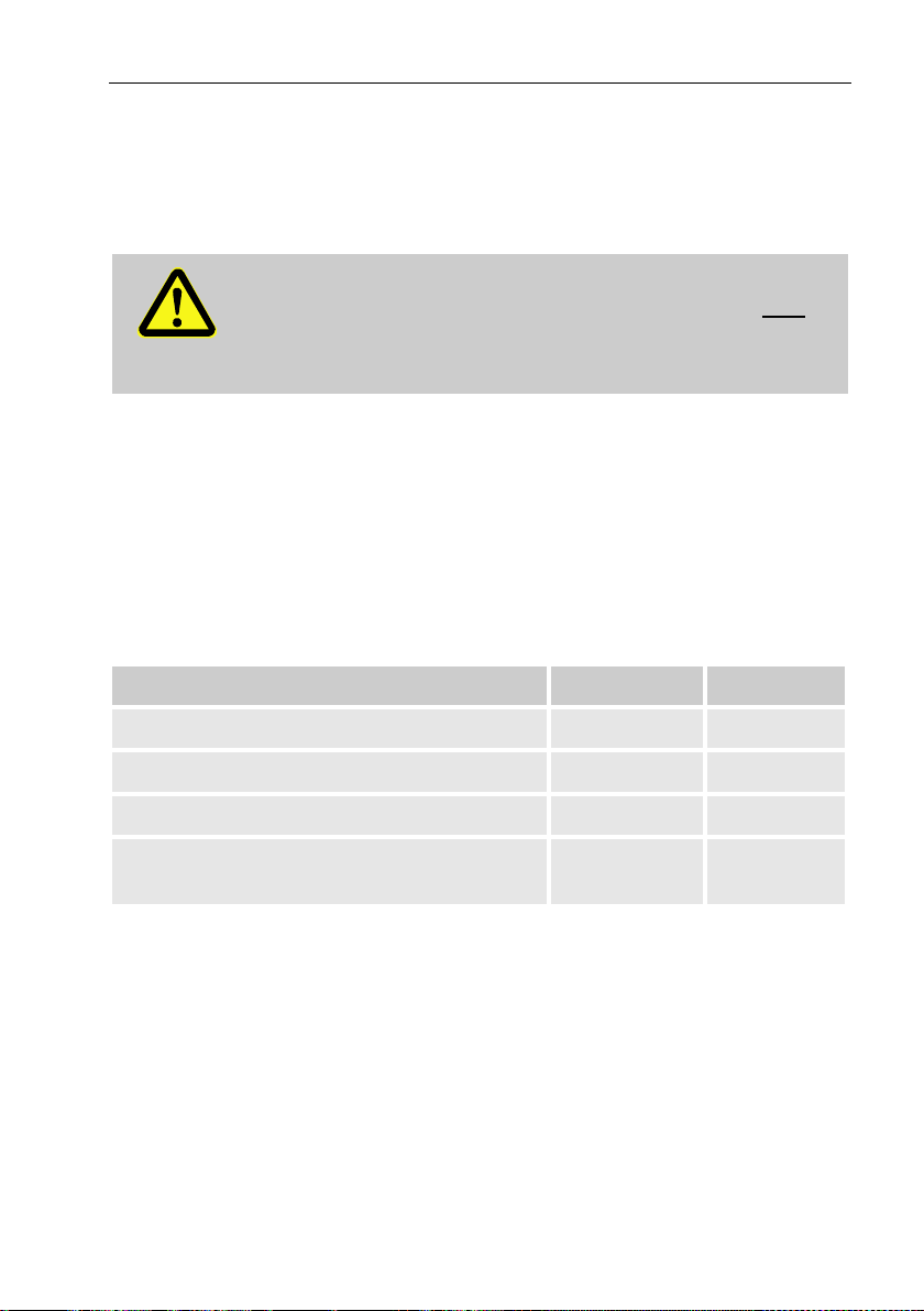
3.9 Labelling
The label is placed on the front panel of the device (see “Construction and
Function” chapter).
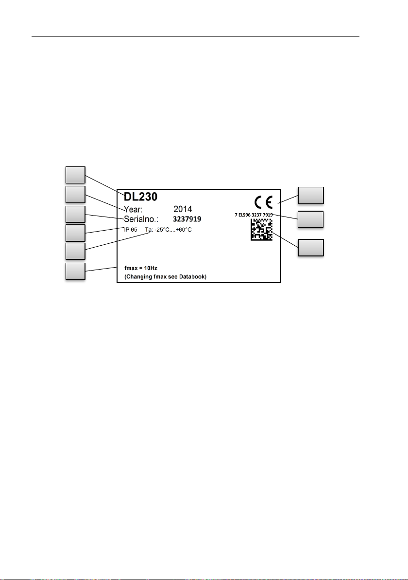
3.9.1 Designation Data Logger
The designation of the DL230 contains the following information:
III.: 1
1 Type designation
6 Maximum input frequency
2 Year of manufacture
7 CE marking
3 Serial number
8 Manufacturer independent
identification number
4 IP protection class data
5 Ambient temperature range
9 Datamatrix Code
1
2
3
4
5
6
9
7
8
Page 29

Technical data 29
3.9.2 ATEX marking
The plates for the "ATEX" marking of the DL230 are located on the top
panel of the device housing.
3.9.2.1 Associated apparatus for Zone 0 and 1
III.: 2
1 Manufacturer and address
4 ATEX-marking
2 Type designation of the device
5 Permissible ambient
temperature range
3 Identification number on the plate
3.9.2.2 Zone 2
III. 3
1 Manufacturer and address
4 ATEX-marking
2 Type designation of the device
5 Permissible ambient
temperature range
3 Identification number on the
plate
2 4 3
5
1
2
4
3
5
1
Page 30

30 Technical data
3.9.3 Device software Identification
◼ Move the cursor using the arrow keys to the "Serv." register and to the
values "Vers" (device software version) and "Chk" (checksum) via the
following path:
Serv. Identification Data Logger Vers or Chk
◼ The checksum "Chk" can be recalculated for verification purposes by
pressing the ENTER button.
Page 31

Construction and Function 31
4 Construction and Function
4.1 External view
III. 4
1 Display
6 Cable glands
2 Function key
7 Arrow keys
3 Optical interface
8 Enter button „ENTER“
4 Escape button „ESC“
9 Aerial
5 Hinge
10 Sealing eyelets
1
2
3
4
5
6
7
9
8
10
Page 32

32 Construction and Function
4.2 Internal view
III. 5
1 Connections for counting and
signal inputs DE1 to DE4
2 Connections for pulse and
signal outputs DA1 to DA2
3 Device battery connections
4 Connections for the power
supply unit
5 Modem battery connections
6 Modem with SIM card holder
7 Connector for interface
boards (optional use in place
of the modem)
4.3 Short description
The DL230 data logger is used to determine maximum load and to register
load profiles in gas plants for special-rate clients. Up to four meters or lowfrequency pulse outputs from volume correctors can be connected to the
data logger. This means that the device is suitable for plants with more
than one measurement.
Two of the input channels can also alternatively be connected to encoder
counters. Inputs which do not capture consumption information or original
meter readings can also be parameterized as status inputs.
1 2 3 4 5 6 7
Page 33

Construction and Function 33
Simple monitoring functions are possible with this. Events can be stored in
an archive, emitted as a status signal or transmitted to a central location via
SMS if required.
Two digital outputs can be used to transfer consumption information or to
signal warnings and alarms.
Energy supply is with lithium batteries. In addition, the device can also be
equipped with a 230VAC power supply unit.
For data communication purposes an integrated modem is available, which
supports the GSM, GPRS and UMTS (2G and 3G) radio standards. Alternatively, communication modules can be used for Ethernet communication
or for communication via RS232/RS485 interface.
Use of the DL230 is via 7 keys and an alphanumeric display on the front
panel.
4.4 Connections
The DL230 memory can be connected to:
– a maximum of three batteries (2x device batteries and 1x modem bat-
tery or 1x device battery and 2x modem batteries)
– Optional 230V connection to an internal power supply unit
The following can be used to monitor and record data and to transmit data
and program functions:
– 4 counting and signal inputs DE1, DE2, DE3, DE4
– 2 pulse and signal outputs DA1, DA2
– Integrated GSM/GPRS modem
– Optical data interface
Further details on the connection possibilities for the DL230
and the available equipment versions can be found in the
"Technical Data" chapter and in chapter "Assembly, Connection and Putting into Operation".
Page 34

34 Assembly, Connection and Putting into Operation
5 Assembly, Connection and Putting into Oper-
ation
5.1 Assembly
The DL230 can be operated as associated apparatus for ATEX zone 0
or 1 and inside ATEX zone 2. Notice the yellow ATEX marking on each
device.
When using in zone 2, the following warning applies:
DANGER!
The DL230 must not be used in Zone 0 or Zone 1!
WARNING!
When using in Zone 2 may present a risk of explosion!
– Do not open when an explosive atmosphere may be
present!
– Potential electrostatic charging hazard: Do not rub
against the display-window!
– Notice the intrinsic safety parameters of chapter 3.7.3.1
when connecting the serial interface.
The DL230 can either be mounted on a wall or a pipeline.
Should problems arise during assembly, e.g. with regard to
the selection of suitable assembly tools, please contact our
customer service team (see "General" chapter).
Page 35

Assembly, Connection and Putting into Operation 35
5.1.1 Assembly on a pipeline
Mount the DL230 to a pipeline using an A2 universal bracket with a pipe clamp (see Appendix) as well as corresponding cylinder screws.
III. 6
1. Screw into place with the aid of two self-tapping screws for plastic 4x13
mm (III. 6: 1 ) cylinder screws, insert the A2 universal bracket in the
boreholes provided (III. 6: 3 ) on the DL230 (III. 6: 2 ).
2. Tighten the screws so that the bracket is sitting in a fixed position.
3. The A2 universal bracket (III. 6: 3 ) and the device (III. 6: 2 ) should be
fastened to the pipeline (III. 6: 5 ) using the pipe clamp (III. 6: 4 )
4. The device should be mounted on the pipeline in such a way that it is in
a fixed position and cannot fall down or twisted.
WARNING!
When using longer self-tapping screws then there is a risk
of leaks in the housing
2
3
1
4
5
Page 36

36 Assembly, Connection and Putting into Operation
5.1.2 Assembly on a wall
The DL230 can be mounted on the wall without opening the
housing. The holes are accessible by pressing the grey covering strips on both the right and left-hand side of the cover
out-wards at the small groove.
III. 7
1. Bore four holes in the positions marked on the wall (see dimensions
in III. 7).
2. Select wall plugs, which correspond to the size of the screws and
insert these in the boreholes in the wall.
3. Use four universal screws 50mm x 5mm for attaching the DL230 to
a wall.
Page 37

Assembly, Connection and Putting into Operation 37
5.2 Connection
The DL230 is available as officially calibrated or a factory calibrated device. Information regarding additional equipment
versions of the DL230 can be found under www.elsterinstromet.com.
DANGER!
The connection of non-intrinsically-safe or nonassociated apparatus presents a risk of explosion!
The operation of the DL230 as associated apparatus for zone
0 or 1 and the connection of non-intrinsically-safe equipment
which exceeds those conditions and limit values specified in
the declaration of conformity, presents a risk of explosion.
Therefore:
– When the DL230 is used as associated apparatus only
devices with intrinsically-safe circuits and electrical data
that corresponds to those requirements stipulated in the
declaration of conformity for the DL230 (see Appendix),
should be connected.
– When connecting the DL230 and putting it into operation, the guide-
lines of the corresponding EN 60079-0 and EN 60079-14 standards
should be observed.
– The wiring of the connections should be professionally carried out by a
gas specialist or a calibration officer.
– Active outputs cannot be switched.
– Connect unused cable glands as per EN 60079-14 with the help of a
plug or a suitable screw cap.
To program the device and carry out further applications the optical interface of the DL230 (see the "Construction and Function" chapter) can be
used. Further details can be found under www.elster-instromet.com.
The connections described below should only be sealed by
a calibration officer. If the DL230 is used for operations,
which are not subject to calibration regulations, the seals on
the respective connections can be omitted.
Page 38

38 Assembly, Connection and Putting into Operation
5.2.1 Connecting meters
For the purpose of measuring consumption the pulse transducers from up
to four meters can be connected to the DE1 to DE4 digital inputs of the
DL230. Alternatively, encoders can be connected to inputs DE1 and DE2.
III. 8
Further details and special features
regarding the use of the pulse
transducer and encoder are
described in the following subchapters.
The wire cross-section for the connection to the DL230
inputs is 0.3 … 2.5 mm
2
.
When using stranded wire, use appropriate wire ferrules.
Use only cables, which fit to the cable glands in order to
keep IP protection class also after the installation.
Minimum cable diameter:
Cable gland M12 ≥ 5 mm
Cable gland M16 ≥ 5,5 mm.
5.2.1.1 Connection to a pulse transducer
1. Connect the meter's pulse transducers to the DE1 to DE4 terminals (III.
8) of the DL230. The polarity can be freely selected (the symbols "+"
and "-" on the terminals are used for the connection of other pulse
transducers or encoders).
2. Adjust the measurement parameters, e.g. the cp value (pulse constant),
as described in chapter 5.3.1.2.
5.2.1.2 Connection to an encoder
1. Connect the meter's encoder(s) to the DE1 and DE2 terminals (III. 8) of
the DL230.
The polarity should be taken into consideration, i.e. connect the "+" of
the encoder to the "DE1 +" terminal and "-" to the "DE1 -" terminal
respectively.
2. Adjust the measurement parameters, e.g. the encoder type, as described in chapter 5.3.1.3.
Page 39

Assembly, Connection and Putting into Operation 39
5.2.2 Sealing the input terminals
After connecting to the meter as per chapter 5.2.1 the respective DE1 to
DE4 input terminal must be sealed for official calibration measurements.
For this purpose, terminal covers are provided in the bag of accessories. If
required, these should be screwed over the connected terminals and an
adhesive seal should then be bonded to the fastening screw (see chapter
5.3.2).
5.2.3 Connecting the power supply
5.2.3.1 Power supply for the DL230 with integrated power supply unit
DANGER!
Danger to life from electrical current!
Touching live parts poses an imminent danger to life.
Therefore:
– Works on the electrical components of the device, i.e.
the connection of the power supply unit, should solely be
carried out by qualified electricians.
– When performing all works to the electrical system,
switch off the power, secure it against an accidental
restart and check to ensure that the voltage has been
cut.
– Keep moisture from live parts away. This could lead to
short-circuit.
The power supply unit to connect the 230 V~ power supply, is
in-built into the base of the DL230.
III. 9
1. Switch off the supply voltage and secure
it against an accidental restart!
2. Connect the 230V~ supply voltage to the
terminal block ( 1 ) of the power supply.
Terminal "PE" is the connection for the
protective conductor (protective
earthing).
1
Page 40

40 Assembly, Connection and Putting into Operation
The wire cross-section for the connection to the integrated
power supply unit is 0.3 … 2.5 mm
2
.
When using stranded wire, use appropriate wire ferrules.
Use only cables, which fit to the cable glands in order to keep
IP protection class also after the installation.
Minimum cable diameter:
Cable gland M12 ≥ 5 mm
Cable gland M16 ≥ 5,5 mm.
DANGER!
Danger to life from electrical current!
Connect the protective earthing of the mains power supply
to the J2 screw terminal, connection "E"!
5.2.4 Connect outputs of the DL230
DANGER!
The connection of non-intrinsically-safe or nonassociated apparatus presents a risk of explosion!
The operation of the DL230 as associated apparatus for zone
0 or 1 and the connection of non-intrinsically-safe equipment
which exceeds those conditions and limit values specified in
the declaration of conformity, presents a risk of explosion.
Therefore:
– When the DL230 is used as associated apparatus only
devices with intrinsically-safe circuits and electrical data
that corresponds to those requirements stipulated in the
ATEX declaration for the DL230 (see Appendix), should
be connected. Notice also the limitations of chapter 3.6.1.
– Screw the terminal covers over the connected output
terminals again.
The wire cross-section for the connection to the DL230 out-
puts is 0.3 … 2.5 mm
2
.
When using stranded wire, use appropriate wire ferrules.
Page 41

Assembly, Connection and Putting into Operation 41
Use only cables, which fit to the cable glands in order to
keep IP protection class also after the installation.
Minimum cable diameter:
Cable gland M12 ≥ 5 mm
Cable gland M16 ≥ 5,5 mm.
Different downstream devices can be connected to the
digital outputs of the DL230. The outputs are preconfigured
for this purpose (see chapter 5.3.1.5).
Ill.: 10
1. Remove the terminal cover for the digital
outputs (terminals DA1 and / or DA2) (Ill.: 10).
2. Connect the downstream device to the
corresponding digital outputs (terminals DA1
to DA2) of the DL230 (Ill.: 10).
3. Screw the terminal covers over the connected
terminals after connecting the cables. If
required, a seal should then be bonded to the
fastening screw (see chapter 5.3.2).
4. If necessary, adjust the cp value (pulse
contact) for the pulse outputs as described in
chapter 5.3.1.5.
5.2.4.1 Electrical insulation of the outputs
In standard cases, all negative poles of the outputs are electrically connected to the motherboard.
For special applications, i.e. switching a positive pole, each output can be
electrically separated from the motherboard and from the other outputs.
CAUTION!
Reduced battery life
Activation of electrical isolation of outputs reduces battery life
when operating the battery.
It is then impossible to give a reliable prediction of the remaining battery life.
Page 42

42 Assembly, Connection and Putting into Operation
An electrically-insulated output only requires electricity if the
output is active (switched-on). You can therefore minimize the
negative influence of an electrically-insulated output on the
battery life by setting the pulse duration to the lowest possible
value when using it as a pulse output.
The configuration software "enSuite" is suitable for this purpose.
The electrical insulation of the outputs is not an approved
electrical isolation in accordance with ATEX. An approved Exisolator is required when using the device as associated
apparatus in Ex zone 0 or 1.
In order to activate the electrical insulation of an output, move the switch
lever behind the corresponding output terminal away from the terminal:
Ill.: 11
Switch for electrical isolation
Output DA2 is electrically isolated
(the slider on the switch is up)
Output DA1 is not electrically isolated
(the slider on the switch is down)
Page 43

Assembly, Connection and Putting into Operation 43
5.3 Putting into operation
5.3.1 Configuration of measurement parameters
If the DL230 is subject to calibration regulations, the works
described below should only be performed by legally
authorized individuals.
The necessary operating parameters can be adjusted using the free
configuration program "enSuite", which is available under www.elsterinstromet.com.
If the program is not available, the configuration can also be carried out
using the keyboard as described below (see chapter 5.3.1.2).
Before adjusting the measurement parameters via the
keyboard, please read chapter 6 to learn how the device is
operated.
5.3.1.1 Opening the calibration lock
The calibration lock is located at the back of the housing cover in the form
of a button, and this can be secured by means of an adhesive label. This
button must be pressed in order to adjust the values and parameters protected by configuration regulations.
Ill.: 12
Position of the
push-button to
open the calibration lock.
Page 44

44 Assembly, Connection and Putting into Operation
5.3.1.2 Adjusting the parameters for the pulse transducer of the meter
If a pulse transducer is connected as per 0 then adjust the input mode and
the cp value as follows:
1. Setting the input mode:
– Move the cursor to the "Serv." tab and via the path below to the input
mode "Md.E1":
Serv. Input 1 Settings Md.E1
– Press the ENTER button The set value flashes.
– Repeatedly press one of the or arrow keys until the text "Pulse
Input" flashes.
– Press the ENTER key to confirm the value setting. The input value can
be deleted by using the ESC key.
2. Setting the cp (pulse constant) value:
– Move the cursor to cp value "cp.E1" in the same path
– Press the ENTER button. One of the value's digits flashes.
– Move the cursor to the digits using the or arrow keys and update
them using the or arrow keys.
– Press the ENTER key to confirm the value setting. The input value can
be deleted by using the ESC key.
The same process can also be used for the other inputs, inputs 2 to 4.
5.3.1.3 Activating encoder mode
If an encoder is connected as per 5.2.1.2, the encoder mode is activated as
follows:
Start the "Encoder Recognition" function using the DL230 keypad as
follows:
– Move the cursor to the "Serv." register and to the value "Md.I1" (input
mode) via the following path:
Serv. Input 1 Parameter settings Md.I1
– Press the ENTER button the set value flashes.
– Repeatedly press one of the or arrow keys until the value "Auto-
Encoder" flashes.
– Press the ENTER key to confirm the value setting. Input can be can-
celled using the ESC key.
– Wait until "Auto-Encoder" is replaced by another value. This can take
up to a minute as the DL230 activates and test all known encoder protocols consecutively.
Page 45

Assembly, Connection and Putting into Operation 45
– On successful detection the DL230 displays the label "Vo1" on the me-
ter reading of the meter:
Serv. Input 1 Vo1
Unlike the "Auto Detect" function, you can also select the connected
encoder type directly under "Md.I1".
Serv. Input 1 Parameter settings Md.I1
The following encoder types can be selected:
Md.E1
Description
Enc.Namur a
Encoder with Namur a protocol
Enc.SCR EDIS
Encoder SCR with EDIS95 protocol
Enc.SCR OBIS
Encoder SCR with OBIS05 protocol
Enc.SCR+EDIS
Encoder SCR+ with EDIS95 protocol
Enc.SCR+OBIS
Encoder SCR+ with OBIS05 protocol
Enc.Nam. a-b
Encoder with Namur a and b protocols
The same process can be used for input 2.
With the parameter "EZyk" you can set for both encoder inputs at what in-
tervals the encoder is read out. Default is 900 seconds (15 minutes).
Changing this parameter has a significant impact on battery life !
"EZyk" can be found in the display under the path:
Serv. Device settings Measurement
5.3.1.4 Adjusting meter readings
To control the measuring of volumes, the meters (V1 to V4) of the DL230
can be adjusted to the same respective value as the meters connected
when the calibration or administrator lock is open (with an entry in the PTB
log).
– Open the calibration lock or the administration lock
– Move the cursor to the "Serv." register and to the value "V1", "V2", "V3"
or "V4":
Serv. Input 1 V1
Serv. Input 2 V2
Serv. Input 3 V3
Serv. Input 4 V4
– Press the ENTER button. One of the value's digits flashes.
– Move the cursor to the digits using the or arrow keys and update
them using the or arrow keys.
Page 46

46 Assembly, Connection and Putting into Operation
– Once you have changed all of the digits, press the ENTER key in order
to confirm your entry. The input value can be deleted by using the ESC
key.
5.3.1.5 Configuration of the outputs
The cp values (pulse constants) for the outputs can also be
configured using the enSuite software.
The following functions are preset ex-factory for the outputs:
Output
Function
DA1
Pulse output for volume "V1" (cp.A1= 0.1)
DA2
Pulse output for volume "V2" (cp.A2= 0.1)
The cp value of an output indicates how many pulses are emitted per cubic
meter. A cp value of 0.1/m3 (0.1 pulses per m3) means that e.g. a pulse is
emitted per 10m3.
To change the cp values for output 1 or output 2, move the cursor to the
"Serv." register and go to "cp.A1" (for output 1) or "cp.A2" (for output 2) via
the following path:
Serv. Outputs Output 1 cp.O1
or Serv. Outputs Output 2 cp.O2
◼ Press the
ENTER
button a digit of the cp value will flash.
◼ Move the cursor to the digits using the or arrow keys and update
them using the or arrow keys.
◼ Press
ENTER
, so that the value setting is confirmed. The input value can
be deleted by using the ESC key.
Aside from the settings described here, a range of other functions can be configured for the outputs, e.g. status information
or time-synchronous pulses.
A complete description can be found in the DL230 Application
Manual that can be downloaded under www.elsterinstromet.com.
5.3.1.6 Setting the daylight-saving time
◼ Move the cursor to the "Serv." register and to the "MdTim" value (day-
light saving mode) via the following path:
Serv. Date and time MdTim
◼ Press the ENTER button the set value flashes.
◼ Change the value using the arrow keys or :
Page 47

Assembly, Connection and Putting into Operation 47
MdTim
Description
CEST off
No switchover to daylight saving time
(CEST = Central European Summer Time)
CEST auto
Automatic conversion to summertime in accordance
with EU regulations
CEST man.
The start and end of daylight saving time is configured
by the control centre every year.
◼ Press the ENTER button to confirm the set value. The input value can
be deleted by using the ESC key.
5.3.1.7 Deleting the measurement archive
Deleting the archive is not absolutely necessary when putting
the device into operation.
◼ Move the cursor to the "Serv." register and to the "Clr.A" value (delete
measurement archive) via the following path:
Serv. Edit and delete Clr.A
All measurement archives (no logs) will be deleted.
In order to ensure that the archive is not accidentally deleted,
the serial number of the DL230 must be entered whilst the
calibration lock is open (this number is located on the
identification plate of the device).
◼ Press the ENTER button. One of the value's digits flashes.
◼ Move the cursor using the arrow keys or to the digits and enter the
serial number of the device using the arrow keys
or .
◼ After you have entered the serial number of the device, press the
ENTER button to confirm the input. The input value can be deleted by
using the ESC key.
5.3.1.8 Deleting the Certification Data Log
The log can only be deleted if the calibration lock is open.
◼ Move the cursor to the "Serv." register and to the value "ClCDL" (delete
certification data log) via the following path:
Page 48

48 Assembly, Connection and Putting into Operation
Serv. Edit and delete ClCDL
◼ Press the ENTER key "0" flashes.
◼ Change the value using the arrow buttons or to "1".
◼ After you have entered the value, press the ENTER button to confirm
the input. The display shows as "busy" temporarily.
The certification data log is then deleted. The input value can be deleted
by using the ESC key.
5.3.1.9 Closing and securing the calibration lock
After all settings subject to calibration regulations have been adjusted,
close the calibration lock in the same way that it was opened: Press the
buttons described in chapter 5.3.1.1 once again.
The calibration switch is secured with an adhesive label as described in
chapter 5.3.2.2.
5.3.1.10 Use of the "HT/LT switch-over"
The DL230 also offers an option to carry out the switch over from the high
tariff meter (HT) to the low tariff (LT) meter.
Whether such a switch over has been parameterized can be found under:
Serv. Input 1 Parameter settings HTLT1
or Serv. Input 2 Parameter settings HTLT2
or Serv. Input 3 Parameter settings HTLT3
or Serv. Input 4 Parameter settings HTLT4
If the displayed value is "-.-.-", then no switch over took place. If the value is
not equal to "-.-.-", then a switch over to the set event is taking place.
In principle two settings are possible:
a) Meter 1 counts, meter 2 does not
b) Meter 1 counts at high tariff (HT) and meter 2 at low tariff (LT)
In case b) the switch over between HT and LT should be parameterized via
a settings file. Switch over either takes place in a "time-dependent" manner
or "controlled by an input". With the inactive meter, the short description will
be shown flashing.
Adjustment is simple to carry out via enSuite configuration
software.
Parameterization of the device is described in the DL230
application manual.
,
Page 49

Assembly, Connection and Putting into Operation 49
5.3.2 Sealing
5.3.2.1 External view
Ill.: 13
1 Possible sealing point to secure the identification plate via adhesive seal.
2 Optional user lock: Sealing the cover by means of wire seals through the
sealing eyelet at the top and the hinge at the bottom.
5.3.2.2 Internal view
Ill.: 14
1 Sealing point to secure the calibration switch.
2 Sealing points to secure the circuit board cover.
3 Sealing points to secure the terminal covers of the inputs and outputs
used.
1
2
2
1
2
3
Page 50

50 Assembly, Connection and Putting into Operation
These sealing points Ill.: 14/3 to secure the pulse inputs and
pulse outputs are subject to national regulations
(cf. WELMEC 11.1, chapter 2.7.1).
Depending on the legal situation in the respective country of
use, seals produced by legally authorized manufacturers or the
meter operators, should be used.
5.3.3 Closing the housing
CAUTION!
Damage to property caused by improper device closure!
If the device is not properly closed cables can get pinched
and cause damage.
Therefore:
– Please ensure that the cable ducts are positioned cor-
rectly when closing the device.
Ill.: 15
1. The grey covering strips on both the right and left-hand side of the cover are pressed outwards at the small groove ( 2 ). This means that the
screws on the cover become visible.
2. Close the housing using the four screws provided ( 1 ).
3. Press the grey covering strips back onto the cover until they snap into
place.
1
2
2
Page 51

Assembly, Connection and Putting into Operation 51
5.3.4 Verifying assembly and connection
WARNING!
Risk as a result of incorrect assembly and connection
Incorrect assembly and connection of the DL230 may lead
to life-threatening situations.
Therefore:
– Assemble and connect the DL230 correctly.
– Sealing should solely be carried out by a calibration
officer.
– Follow the guidelines of DIN EN 60079-14,
DIN EN 60079-0, the ATEX Product Directive 94/9/EC
as well as the ATEX Operating Directive 1999/92/EC
EN.
5.3.5 Data transfer
For the various options available regarding data transmission to a control
centre via the integrated modem then please follow the corresponding
instructions in the DL230 applications manual which can be downloaded
from von http://www.dl230.de/ (DOWNLOADS → Dokumente).
The data transfer settings can be configured without opening the calibration
lock.
Page 52

52 Operation
6 Operation
The "enSuite" software and data interfaces of the DL230 can
be used to perform further applications other than those
described below. Instructions can be found under
www.elster-instromet.com.
6.1 Safety
6.1.1 Personal protective equipment
When working on the device inside a gas-handling plant, personal protective equipment must be worn to minimize risks to health.
– During works on the device, the necessary personal protective equip-
ment must be worn inside the respective plant at all times
– The notices relating to personal protective equipment mounted in the
working area must be followed at all times.
6.2 Operating personnel
The following groups of people are authorized to perform different functions
when operating the DL230.
6.2.1 Instructed personnel
A person instructed on how to operate the DL230, who,
– will be informed of the tasks assigned to them and possible risks result-
ing from inappropriate behaviour, in a training session provided by the
operator.
– is authorized to read and take note of values and parameters using the
control elements of the DL230.
6.2.2 Qualified personnel
A person qualified to operate the DL230, who,
– on the basis of their specialist training, knowledge and experience, as
well as their awareness of the relevant statutory provisions, are in a
position to perform their assigned tasks on the device and are able to
independently identify and prevent possible risks.
Page 53

Operation 53
– is authorized to read and take note of values and parameters using the
control elements of the DL230, and to perform changes which are not
subject to calibration regulations.
6.2.3 Calibration officer
A calibration officer, who,
– on the basis of their professional training, knowledge and experience
and awareness of applicable standards and regulations, is in a position
to perform the works on gas systems. The calibration officer will be
trained on works on devices and installations subject to calibration regulations and will be familiar with the relevant standards and regulations.
– is authorized to read and take note of values and parameters using the
control elements of the DL230, and to perform changes which are subject to calibration regulations.
Page 54

54 Operation
ESC
6.3 Basic principles
As already explained in the "Construction and Function" chapter, the DL230
can be operated and programed using the control elements on the front
panel of the device.
Ill. 16: Front panel of the DL230
1 Alphanumeric display
4 Arrow keys
2 Function key
5 Enter button
3 Escape button
The calibration lock is located on the circuit board built into
the housing cover in the form of a button, and can be sealed
by means of an adhesive label. This button must be pressed
in order to adjust the values and parameters protected by
configuration regulations. For devices protected by
calibration regulations, this may solely be carried out by a
calibration officer.
3
2
1
5
4
Enter
Page 55

Operation 55
6.3.1 Display
The display is divided into the five registers "Main", "Cust.", "Admin",
"Serv." and "Ctrl." under which measurements, settings and other data are
displayed.
Ill. 17 Display layout
1 Cursor
2 Device status
3 Active register
4 Inactive register
5 Frozen display
6 External power supply
7 Reception strength of the
modem
8 Battery charge status
9 Data field
The display in the data field in Ill. 17/ 9 (starting here with "V1") is different
in each of the registers. All other display sections (in the top part of the
screen) remain the same, regardless of the register displayed.
1 2 3 4 5 6 7
8
9
Page 56

56 Operation
6.3.2 Button functions
The pressure and arrow buttons have the following functions:
Button
Function
– Jump right to another data list.
– Jump to the second part of a two-part value.
– Jump down through a data list.
– Jump left to another data list.
– Jump up through a data list.
ENTER
– Depending on the respective data class, you can:
Activate the input mode.
Open the respective sub-menu.
Update the corresponding measurement.
ESC
– Depending on the respective data class, you can:
Leave a sub-menu and jump to its entry value (one menu
level up).
Cancel an entry (when in input mode).
+
– By pressing both of the buttons at the same time:
Display the "Main" register.
You can set a value in input mode (reset to start value)
+
– Address display of the current value.
– By pressing the function key, you can:
Display the "Main" register.
Freeze the current display.
Delete the status register.
Page 57

Operation 57
6.3.3 Data recall, display navigation
Using the arrow keys , , , you can move the cursor around the
display and switch to the other values.
Pressing the "ESC" key means you move up a level until you reach one of
the "Main", "Cust.", "Admin", "Serv." or "Ctrl." registers
( 6.3.1, Ill. 17). The active register, over which the cursor is hovering, is
presented with a light-coloured background (Ill. 18/1).
In the "register" bar, you can move the cursor to other registers using the
arrow keys and to display their content.
Ill. 18: "Cust." register
1 Active register
2 Value with corresponding timestamp
The "Cust." register contains more data than can simultaneously be
displayed. The arrow key is used to move the cursor from the register to
the data field (the bottom part of the display). By moving the cursor to the
lowest visible value, the display can be shifted upwards by re-pressing the
button to display further data. The button can also be used to move
the cursor and therefore the display upwards by moving to the highest
visible value. If the cursor hovers over a value which has been saved with a
corresponding timestamp, it will automatically display this value.
(Ill. 18/2)
1
2
Page 58

58 Operation
6.3.4 Meaning of status symbols
The status symbols displayed in the first line have the following meaning:
Ill. 19: Status symbols in the display
1 Status Symbol
Symbol
Description
In the upper left-hand side of the screen, individual letters are
displayed as symbols for the following signals:
ok.
No special messages
A
Alarm – Collective message for "any alarm"
a
Administrator lock – The administrator lock is open.
B
Battery warning – The battery is almost empty
L
Log – The certification data log is full.
M
Measurement error – The connected gas meter encoder is not
giving accurate meter readings.
o
Online – A data transfer is underway.
P
Programing mode – The calibration lock is open.
W
Warning – Collective message for "any warning"
If one of these letters flashes, the indicated status remains active. If one
of the letters is displayed constantly, the indicated status is no longer active but must be acknowledged.
For further details on the meaning and potentially necessary procedures,
see chapter 8.1.4 "Behaviour"
1
Page 59

Operation 59
Symbol
Description
Frozen display
The displayed values have "frozen" (are not up-to-date). The
current values will be displayed after pressing any button.
The display freezing can be caused by pressing the function
key .
External power supply
This symbol indicates that the DL230 is supplied via the inte-
grated power supply unit.
Signal strength of the radio network for the GSM modem.
This symbol will only be shown if the modem is active.
Battery life display
6.3.5 Error messages when entering values
If a value has been entered incorrectly via the keyboard, input error messages will be displayed.
This is shown as follows: -- x --
x = error code according to the following table
Code
Description
1
The archive is empty. No values have been entered.
2
The archive value cannot be read.
The archive may already have been opened by the interface
for readings.
4
This parameter cannot be changed (constant).
5
You are no authorized to change this value.
To change this value, a corresponding lock must be opened.
6
Invalid value
The value entered is outside the permissible limits.
7
Incorrect code
The code entered (numerical code) is incorrect; the lock will
not be opened.
Page 60

60 Operation
Code
Description
11
Entry based on specific setting or configuration not possible,
e.g. The input of Vo is not possible in encoder mode.
12
The input of this source (address) is not permitted.
13
Entry based on specific setting or configuration not possible,
e.g.:
The "Clr.X" function can only be performed once the time has
been set to its start value with the key combination
+ (initialized).
20
Value for the user-specific display is not defined
The value to be displayed can be defined by the user by
entering the address. As this address has not yet been
entered, no value will be displayed.
21
The value can only be changed when the calibration lock is
open as the PTB log is full.
6.3.6 Access rights
The following parties can access the DL230.
Access
Description
PL
Calibration officer
CDL
Certification Data Log
A
Administrator
C
Customer
-
No access
Each access party has one lock and a corresponding key.
The access rights apply for entries made via the keyboard, and for access
via the optical or integrated modem interface. If the lock is closed, all
attempts to enter values will result in a corresponding error message being
displayed (see chapter 6.3.5, "Error messages when entering values").
For data protection reasons, reading values from the interfaces is only
possible if at least one of the locks is open.
Page 61

Operation 61
6.3.6.1 Calibration lock
The calibration lock is used to protect parameters subject to calibration
regulations. This includes all values, which influence volume readings.
The calibration lock is designed as a button, which is positioned inside the
DL230 housing underneath the circuit board cover. It can be protected with
an adhesive label (see chapter 5.3.1.1, "Opening the calibration lock").
The calibration lock is opened by pressing the button ("P" symbol flashes in
the display) and is closed again by pressing the same button ("P" symbol
fades). It can also be closed by deleting the value "St.PL" (see chapter
6.4.6, "Ctrl." register (control)) via the keyboard or interface. Using the
configuration software "enSuite",
a time can also be set (in minutes) after which the calibration lock will
automatically close.
The level of protection can be changed for all parameters upon request,
particularly for applications, which are not subject to German calibration
guidelines.
For example, parameters, which are protected by the calibration lock as
standard, can also be protected with an administrator's lock or a certification data log.
6.3.6.2 Certification Data Log
The certification data log is activated as standard but can also be disabled.
The corresponding parameters will then be protected by the calibration
lock.
Using the "certification data log" as per PTB-A 50.7, several parameters
subject to calibration regulations can also be adjusted when the calibration
lock is closed. This is subject to the following conditions:
• The administrator's lock (see below) must be open.
• There are at least three free entries in the certification data log.
The following parameters are set as default:
• "Md.I1" to "Md.I4" modes for inputs 1 to 4
• "V1" to "V4" Main counter for inputs 1 to 4
• "cp.I1" to "cp.I4" cp values for inputs 1 to 4
• "MP.I1" to "MP.I4" measurement periods for inputs 1 to 4
• "TG.I1" to "TG.I4" daily limits for inputs 1 to 4
• "Clr.A" delete measurement archive
• "HTLT1“ to "HTLT4" settings for HTLT conversion
For every change of a parameter listed under "PL" when the calibration lock
is closed, one row of data will be entered for the value before and after the
change.
If the certification data log is full, it can be deleted using the command
"ClCDL" if the calibration lock is open (see chapter 5.3.1.8).
Page 62

62 Operation
If the calibration lock is opened when the certification data
log is full, it can only be closed again after the calibration
log has been deleted.
6.3.6.3 Administrator and customer locks
Administrator and customer locks are used to protect data which is not subject to calibration regulations, but which should also not be modified without
authorization.
These locks can be opened by entering a code (i.e. the "key") under Cod.A
or Cod.C and are closed by entering "0" for St.AL or St.CL.
These values can be found under the following path:
Admin Device settings Access
or Serv. Device settings Access
A time (in minutes) can also be set here for each lock, after which it will automatically close. AutAL, AutCL, AutPL
6.4 Data register content
6.4.1 Access rights
The "access" column in the tables in the following chapter describes which
lock must be opened in order to change a parameter. All parameter
changes are saved in a log.
Access
Description
E
Calibration officer
PL
Certification Data Log
A
Administrator
K
Customer
-
No access
Page 63

Operation 63
6.4.2 "Main" register (main display)
An overview of the most important measurements is presented in the
"Main" register. Depending on settings, the contents (see Chapter 6.4.6.5)
may vary.
Display
Description
Unit
Access
Address
V1
Main counter input 1
m3
PL
1:200
V2
Main counter input 2
m3
PL
2:200
V3
Main counter input 3
m3
PL
3:200
V4
Main counter input 4
m3
PL
4:200
Time
Time on the device
-
PL
1:400
6.4.2.1 V1 to V4 – Main counter of the respective input
This meter counts the incoming pulses and converts these into a volume
via the cp value set. To control the measurements, the V1 can be kept at
the same level as the meter at this input when putting the device into
operation ( chapter 5.3.1 "Configuration of measurement parameters").
6.4.2.2 Vo1 and Vo2 - Original meter readings of the respective inputs
This meter is only available in encoder mode. It shows the original meter
reading of the respective meter, which was transmitted by the encoder.
This means that Vo is always automatically on the state of the meter and
cannot be changed.
6.4.2.3 Time – Date and time
The time displayed is updated every 900 seconds in battery operation and
naturally, the update takes place immediately when switching on the
display. In mains operation and during communication, updating takes
place every two seconds.
Page 64

64 Operation
6.4.3 "Cust." Register (Customer)
This register is used to display and check special device settings and
conditions. This application is provided for customers.
This register can be freely programed by the user via the enSuite configuration software.
The following parameters are programed ex-works:
Display
Description
Unit
Access
Address
V1MPL
Metering period maximum in
the previous month at input 1
m3 - 3:161
V2MPL
Metering period maximum in
the previous month at input 2
m3 E 7:161
V3MPL
Metering period maximum in
the previous month at input 3
m3 E 11:161
V4MPL
Metering period maximum in
the previous month at input 4
m3 - 15:161
V1DGL
Daily maximum in the previous
month at input 1
m3 - 4:161
V2DGL
Daily maximum in the previous
month at input 2
m3 - 8:161
V3DGL
Daily maximum in the previous
month at input 3
m3 - 12:161
V4DGL
Daily maximum in the previous
month at input 4
m3 - 16:161
V1MPL∆
Consumption during the last
measurement period at input 1
m3 - 1:161
V2MPL∆
Consumption during the last
measurement period at input 2
m3 - 5:161
V3MPL∆
Consumption during the last
measurement period at input 3
m3 - 9:161
V4MPL∆
Consumption during the last
measurement period at input 4
m3 - 13:161
Page 65

Operation 65
6.4.3.1 VxMPL – Maximum measurement period counter of the
respective input in the previous month
The displayed value is the metering period maximum of the counter input of
the previous (Last) month. The maximum time stamp is displayed in the fol-
lowing line after moving the cursor to the value "VxMPL".
The maximum values from the past 15 months can be requested in the
monthly archive of the respective input (see chapter 6.4.4 "Admin" Register
(Administrator).
6.4.3.2 VxDGL – Maximum daily counter of the respective input in the
previous month
The value is the daily maximum of the counter input of the previous (Last)
month dependent on the daily limit. The maximum time stamp is displayed
in the following line after moving the cursor to the value "VxDGL".
The maximum values from the past 15 months can be requested in the
monthly archive of the respective input (see chapter 6.4.4 "Admin" Register
(Administrator).
6.4.3.3 VxMPL∆ – Consumption of the last measurement period of the respective input
The value is the difference between the meter readings at the end of the
last and the second-to-last measurement periods of the respective input.
The consumption time stamp is displayed in the following line after moving
the cursor to the value "VxMPL∆".
Page 66

66 Operation
6.4.4 "Admin" Register (Administrator)
This register is used to display and check special device settings and
conditions. This application is provided for meter operators.
Display
Description
User values3
Sub-menu for user-specific parameters
Input 1
Sub-menu for values and parameters for input 1
Input 2
Sub-menu for values and parameters for input 2
Input 3
Sub-menu for values and parameters for input 3
Input 4
Sub-menu for values and parameters for input 4
Tariff programs
Sub-menu for revaluation and the corresponding
parameters
Measured
values
Sub-menu for measured values and the corresponding
parameters
Archives
Sub-menu for existing archives in the device
Status
Sub-menu for current status, status register and logs
Date and time
Sub-menu for date, time and the corresponding
parameters
Batteries
Sub-menu for the device battery and the corresponding
parameters
Outputs
Sub-menu for both outputs and the corresponding
parameters
Interfaces
Sub-menu for existing interfaces in the device
Device settings
Sub-menu for all device settings
Identification
Sub-menu for the identification of the gas system
6.4.4.1 SReg – Status register (total)
All messages since the last manual clear are collected in the status
register. It can be seen here what e.g. has occurred since the last visit. The
reports can be (Serv. Status Clr) deleted from the device. Only
alarms and warnings are displayed (see Chapter 8.2) in status registers.
3
In the "User Values" sub-menu, the user can set up to 10 freely programma-
ble parameters and up to 12 freely programmable parameters in a further submenu within this list.
Page 67

Operation 67
6.4.5 "Serv." register (Service)
This register is used to display, check and configure special device settings
and conditions. This application is only intended for service technicians
(specialists) or a calibration officer for putting the device into operation or
maintenance.
Display
Description
Input 1
Sub-menu for values and parameters for input 1
Input 2
Sub-menu for values and parameters for input 2
Input 3
Sub-menu for values and parameters for input 3
Input 4
Sub-menu for values and parameters for input 4
Tariff programs
Sub-menu for revaluation and the corresponding
parameters
Measured
values
Sub-menu for measured values and the corresponding
parameters
Archives
Sub-menu for existing archives in the device
Status
Sub-menu for current status, status register and logs
Date and time
Sub-menu for date, time and the corresponding
parameters
Batteries
Sub-menu for the device battery and the corresponding
parameters
Outputs
Sub-menu for both outputs and the corresponding
parameters
Interfaces
Sub-menu for existing interfaces in the device
Device settings
Sub-menu for all device settings
Identification
Sub-menu for the identification of the gas system
Edit and delete
Sub-menu to activate a range of delete functions
Data book
Sub-menu with information from the device data book
Page 68

68 Operation
6.4.6 "Ctrl." register (control)
This register is used to monitor special device settings. This application is
only intended for service technicians (specialists)
or a calibration officer for putting the device into operation or maintenance.
Display
Value
Unit
Access
Address
St.AL4
Administrator lock: State/close
- - 3:170
Cod.A4
Enter / change administrator
code
- - 3:171
St.PL
Calibration lock: State/close
- - 1:170
Menu
Selection of the display menu
- E 1:1A1
Main
Content of the "Main" register
- A 2:1A1
6.4.6.1 St.AL – Administrator lock: State/close
The administrator lock must be opened in order to modify certain measurement parameters. The administrator lock should be closed when in
normal operating mode. An open administrator lock can be closed by
pressing the "Enter" key and selecting the "locked" option.
Display
Description
locked
The administrator lock is closed.
open
The administrator lock is open.
4
If the device is operated with high-level security (see application manual) then this menu
item is not shown in the display.
Page 69

Operation 69
6.4.6.2 Cod.A – enter / change administrator code
By entering the correct code (hexadecimal characters) here it is possible to
open the administrator lock. After opening the administrator lock, the
existing code can be changed.
Individual characters of the code can have the values 0 to 9
and A to F.
6.4.6.3 St.PL – Calibration lock: State/close
The calibration lock must be opened in order to modify certain
measurement parameters. The calibration lock can only be opened by
pressing the calibration switch on the CPU board. An open calibration lock
can be closed by pressing the "Enter" key and selecting the "locked" option.
The calibration lock should be closed when in normal operating mode.
Display
Description
locked
The calibration lock is closed.
open
The calibration lock is open.
In this case, the "P" will also flash in the upper left-hand
side of the display (see chapter 6.3.4 "Meaning of status
symbols")
6.4.6.4 Menu - Selection of the display menu
In an as-delivered condition, the display of the DL230 has the following five
registers: "Main", "Cust.", "Admin.", "Serv." and "Ctrl.". Registers can be
displayed and hidden for certain purposes using the "Menu" value.
6.4.6.5 Main – Content of the "Main" register
The content of the "Main" display register can be adjusted here.
The default setting is "V1…V4". This corresponds to the content displayed
in chapter 6.3.1.
Display
Description
V1…V4
Displayed: Main counter of inputs 1 to 4, current date
and time of device,
Format: 9 digits before and 4 digits after decimal point
with short descriptions and units
Vo1 V2…V4
Displayed: Original meter reading of input 1, main counters of inputs 2 to 4,
current date and time of device,
Format: 9 digits before and 4 digits after decimal point
with short descriptions and units
Page 70

70 Operation
Display
Description
Vo1,2 V3,4
Displayed: Original meter readings of inputs 1 and 2,
main counters of inputs 3 to 4,
current date and time of device,
Format: 9 digits before and 4 digits after decimal point
with short descriptions and units
large V1 V2
Displayed: Main counters of inputs 1 and 2
Format: 8 digits before and 3 digits after decimal point
with input, short descriptions and units
large Vo1
V2
Displayed: Original meter reading of input 1, Main counter of input 2
Format: 8 digits before and 3 digits after decimal point
with input, short descriptions and units
large Vo1,2
Displayed: Original meter readings of inputs 1 and 2
Format: 8 digits before and 3 digits after decimal point
with input, short descriptions and units
6.5 Use as high-flow display device
The DL230 has an integrated high-load display function and has national
approval.
The following consumption figures are calculated and stored for each of the
four inputs along with timestamps and can be shown on the device when
requested:
- the load registered during the current measurement period (VxMPc)
- the load registered during the previous measurement period (VxMPL)
- the highest load registered within a measurement period within the current
month (VxMPc)
- the load registered during the current day (VxDGc)
- the load registered during the previous day (VxDGL)
- the highest daily load registered during the current month (VxDGc)
The measurement period maximum (VxMPL) and the daily maximum
(VxDGL) of the last 15 months are stored in the monthly archive of the
respective input. The content of this archive can be found under:
Admin Input x Monthly Archive Ix
Page 71

Operation 71
The resulting maximum values of the current month can be found under:
Admin Input x per measuring period and under:
Admin Input x per day
At the end of each month the "resulting maximum values" of the month just
gone are written into the newest data record of the monthly archive. At the
same time, the oldest data record is deleted so that the monthly archive always covers 15 months at most.
The end of the month can be parameterized separately for each input and
takes place at an adjustable time on the first day of each month. This
monthly limit (=daily limit) is set to 6:00 AM as a default setting.
The daily limit (DG.Ix) can be found under the following path:
Admin Input x per day
If at least two entries are still free in the certification data dog then it is possible to change the daily limit when the administrator lock is open. Otherwise, the value can only be changed when the calibration lock is open. All
full hours of the day (0:00 to 23:00) can be set.
Labelling of faulty maximum values in the display is carried out as follows:
Display
Description
The maximum values flash
with their timestamps + "t"
in an archive row.
During creation of a maximum value, the
time or the date is adjusted.
6.6 Use as flow-recording device
The DL230 has an integrated flow-recording registration function and has
national approval.
The meter readings Vx and Vx.P used for billing as well as their
progressions Vx and Vx.P are contained in the measurement period
archive. The progressions always refer to the respective previous archive
row.
The measurement periods can be found under the following path:
Admin Input x MP.Ix
The measurement period is set to "60 minutes" as standard.
If at least two entries are still free in the certification data log then it is
possible to change the measurement periods when the administrator lock is
Page 72

72 Operation
open. Otherwise the value can only be changed when the calibration lock is
open. Sensible and typical values include 5, 10, 15, 20, 30 or 60 minutes.
For monitoring invoicing data on the display, the device is equipped with
the following functions:
• All invoicing-relevant data is displayed under:
Admin Input x Measurement period Ix
• Additional display of the progress of the counter (consumption values)
in the measurement period archive
• Search function for checking archive entries (see Chapter 6.6.1)
• Display of the set measurement period MP Ix and the remaining
duration of the current measurement period under:
Admin Input x MP.Ix or MP.Re
• Labelling of uncalibrated values using an asterisk in front of the short
description
Labelling of faulty measurement periods in the display is carried out as
follows:
Display
Description
All values within an
archive row flash.
A data error (checksum error) was recognized
in the current archive row.
The "delta" values + "c"
flash in an archive row.
A data error (checksum error) was recognized
in the previous archive row.
The "delta" values + "e"
flash in an archive row.
The current or previous archive row was not
generated due to the end of a measurement
period (e.g. adjustment of time).
6.6.1 Search function for checking archive entries
The measurement period archive has a large number of entries. Individual
values from these datasets can be displayed for verification purposes, as
the device includes an archive entry search function. Values can be
searched on in the following archive rows:
• Identification number
• Date and time
• Meter reading
Initially, the search takes place by selecting the desired column in any
archive row. Pressing the "ENTER" key now allows entry of the value to be
searched for in this column. Pressing "ENTER" after entering the search
Page 73

Maintenance 73
value will cause the display to jump to the archive row containing the
entered value. If the entry is not found, it jumps to the next closest entry.
7 Maintenance
7.1 Safety
DANGER!
Danger to life from electrical current!
Touching live parts poses an imminent danger to life. Damage to the insulation or individual components may be lifethreatening.
Therefore:
– Safely protect electrical connections and live
components against possible human contact.
– In the event of insulation damage, switch off the power
supply immediately and arrange for repairs to be carried
out.
– Works on the electrical components of the device, i.e.
the connection of the external power supply unit, should
only be carried out by qualified electricians.
– When performing all works to the electrical system,
switch off the power and ensure that the voltage has
been cut.
– Before performing maintenance works switch off the
power supply and protect against an accidental restart.
– Do not attempt to bypass or deactivate fuses. When ex-
changing fuses, ensure that you adhere to the correct
ampere rating.
– Keep live parts away from moisture. This could lead to a
short-circuit.
Page 74

74 Maintenance
WARNING!
Misuse of batteries may present a risk of injury.
Special care must be taken when handling batteries.
Therefore:
– Do not throw the batteries into the fire or expose these
to high temperatures. There is a risk of explosion.
– Do not charge batteries. There is a risk of explosion.
– Liquids that are produced as a result of misuse may
lead to skin irritation. Avoid all contact with liquids. In the
event of contact, rinse with large quantities of water. If
the liquid enters the eyes, immediately rinse with water
for 10 minutes and seek medical attention.
CAUTION!
Environmentally hazardous substances!
If environmentally hazardous substances are handled
incorrectly this may cause significant damage to the
environment, particularly if they are improperly disposed of.
Therefore:
– The instructions below should be observed at all times.
– Appropriate measures should be taken immediately if
environmentally hazardous substances are accidentally
released into the environment. In cases of doubt, please
inform the responsible local authority about the
damages.
Page 75

Maintenance 75
7.1.1 Personnel
Maintenance works must be carried out correctly.
– The maintenance works described in this document should solely be
carried out by specialized electricians (see "Operation" chapter).
WARNING!
Risk of injury if maintenance works are carried out incorrectly.
Incorrect maintenance may lead to serious personal injury
or material damage.
Therefore:
– Ensure that there is sufficient assembly space before
commencing works.
– Ensure that the installation location is clean and tidy.
Components that are loosely stacked or lying around
can cause accidents.
– If parts have been removed, ensure that they have been
installed correctly, re-mount all fastenings, and adhere
to tightening torque values for screws.
7.1.2 Personal protective equipment
– During maintenance works on the device, the necessary personal pro-
tective equipment for the work must be worn inside the respective
plant.
– The notices relating to personal protective equipment mounted in the
working area must be followed at all times.
7.1.3 Environmental protection
Please observe the following notice regarding environmental protection
when performing maintenance works:
The batteries used contain toxic heavy metals. These must
be treated as special hazardous waste and must be disposed
of in municipal waste collection points or by a waste specialist.
Page 76

76 Maintenance
7.2 Testing and changing device batteries
7.2.1 Changing and connecting device batteries
DANGER!
Using the incorrect batteries may present a risk of
explosion!
Only use batteries prescribed by Elster in accordance with
Chapter 9.1.2.
WARNING!
When using in Zone 2
– Do not open when an explosive atmosphere may be
present!
– Potential electrostatic charging hazard: Do not rub
against the display- window!
WARNING!
Misuse of batteries may present a risk of injury.
Special care must be taken when handling batteries.
Therefore:
– Do not throw the batteries into the fire or expose them to
high temperatures. There is a risk of explosion.
– Do not charge the batteries. There is a risk of explosion.
– Liquids that are produced as a result of misuse may lead
to skin irritation. Avoid all contact with liquids. In the event
of contact with the skin, rinse with plenty of water. If the
liquid enters the eyes, immediately rinse with water for 10
minutes and seek medical attention.
The batteries can be exchanged without a calibration officer, as the housing does not need to be sealed.
In the delivered state, one or two device batteries are con-
nected to the base plate of the DL230 depending on the or-
der. With two batteries, the service life is doubled provided
that the settings remain the same.
Page 77

Maintenance 77
Always leave at least one battery connected to the DL230 (to
X5 or X6) when changing batteries. This way, the DL230 will
continue to work whilst the batteries are being changed.
CAUTION!
Reduced battery power!
The simultaneous use of an old and a new battery
considerably reduces battery power.
Therefore:
– When using two batteries always exchange both at the
same time.
Ill.: 20
1. If the external power supply is
connected, then disconnect it.
2. The grey covering strips on both
the right and left-hand side of the
cover are pressed out-wards at
the small groove (Ill.: 20 1 ). This
means that the screws on the
cover become visible.
3. Loosen the four screws
(Ill.: 20 2 ) with which the
housing is connected.
4. Open the cover of the DL230 by
pushing down on it.
Ill.: 21
5. Loosen the screw on the battery
holder Ill.: 21: 1 and pull out the
mounting element for the battery 2 .
The element fits very snugly in the
guides.
6. Mark the old battery using e.g. a felt-
tipped pen or stickers.
7. Choose the free CPU Power con-
nection on the board to connect to
the new battery (Ill.: 22: X5 or X6).
8. Place the new battery onto the base
of one of the three locations
provided for it (Ill.: 21: 3 ).
1 3 2
Page 78

78 Maintenance
Ill.: 22
9. Fix the new battery into place with
the mounting element. The mounting
element can then be fixedly pushed
into the left- and right-hand guides.
10. Remove the old battery from the
housing and dispose of it correctly.
Close the housing using the screws
provided (Ill.: 20 2 ).
12. Re-enter the start capacity of the
batteries, as described in chapter
7.2.2.
13. Check the calculated service life as described in chapter 7.2.3. At
standard measurement conditions (see chapter 3.2.1), the service life
should display at least 96 months. If not, compare the settings with
those for standard measurement conditions and repeat step 12 if necessary.
Please ensure that the new batteries are connected
correctly and are in a fixed position inside the DL230.
CAUTION!
Damage to property caused by improper device
closure!
If the device is not properly closed cables can get pinched
and cause damage.
Therefore:
– Ensure correct positioning of the cable guide when
closing.
Page 79

Maintenance 79
7.2.2 Entering the battery capacity
The battery capacity must be re-entered after changing a
battery.
If the device is operated with high-level security (see appli-
cation manual) then the battery capacity can only be en-
tered using the enSuite software!
◼ To open the administrator lock move the cursor to the "Admin" register
and then via the following path to the "Cod.A" value
(Administrator code entry):
Admin. Device settings Access Cod.A
After delivery, the administrator code for keyboard input is
"00000000".
◼ Press the ENTER button. One of the value's digits flashes.
◼ Move the cursor to the digits using the or arrow keys and update
them using the or arrow keys.
◼ Once you have changed all of the digits, press the ENTER key in order
to confirm your entry. The input value can be deleted by pressing the
ESC button.
◼ To enter the battery capacity move the cursor to the "Serv." register and
to the "Bat.K" value (battery capacity) via the following path:
Admin Batteries Bat.C
◼ Press the ENTER button. One of the value's digits flashes.
◼ Move the cursor to the digits using the or arrow keys and update
them using the or arrow keys.
When using one size D battery, the value 13.0 Ah should
be entered for "Bat.C". When using 2 batteries, the value
26.0 Ah must be entered.
◼ Once you have changed all of the digits, press the ENTER key in order
to confirm your entry. The input value can be deleted by pressing the
ESC button.
◼ To close the administrator lock move the cursor to the "Admin" register
and to the "St.AS" value (Status of administration lock) via the following
path:
Admin. Device settings Access St.AL
◼ Press the ENTER key "open" flashes.
Page 80

80 Maintenance
◼ Move the cursor with the arrow keys or in order to change the val-
ue to "locked".
◼ After making the change, press the ENTER button to confirm the input.
The input value can be deleted by pressing the ESC button.
7.2.3 Display remaining battery power
The calculation of the remaining battery power depends on the
consumed capacity (which is measured) and on the
anticipated future consumption under typical conditions. These
two values lead to the theoretical remaining battery power,
which is displayed under Bat.R. For applications with atypical
high power consumption, this procedure may cause the actual
remaining battery power to drop quicker than the displayed
predicted remaining battery power.
The remaining battery power Bat.R will automatically be
recalculated after entering a new battery capacity Bat.C (see
above). The Bat.R value cannot be edited.
◼ Move the cursor to the "Admin" register and to the "Bat.R" value (re-
maining battery power) via the following path:
Admin Batteries Bat.R
After entering the new battery capacity, a value of
at least 96 months will be displayed in standard
measurement conditions (see chapter 3.2.1) for "Bat.R".
7.3 Changing and testing modem batteries
7.3.1 Changing and connecting modem batteries
DANGER!
Using the incorrect batteries may present a risk of
explosion!
Only use batteries prescribed by Elster in accordance with
Chapter 9.1.2.
Page 81

Maintenance 81
WARNING!
Misuse of batteries may present a risk of injury.
Special care must be taken when handling batteries.
Therefore:
– Do not throw the batteries into the fire or expose them to
high temperatures. There is a risk of explosion.
– Do not charge the batteries. There is a risk of explosion.
– Liquids that are produced because of misuse may lead to
skin irritation. Avoid all contact with liquids. In the event of
contact with the skin, rinse with plenty of water. If the liquid
enters the eyes, immediately rinse with water for 10
minutes and seek medical attention.
WARNING!
When using in Zone 2 may present a risk of explosion!
– Do not open when an explosive atmosphere may be
present!
– Potential electrostatic charging hazard: Do not rub
against the display window!
The batteries can be exchanged without a calibration officer as the housing
does not need to be sealed.
In the delivered state, one or two modem batteries are
connected to the main board of the DL230 depending on the
order. With two batteries, the modem service life is doubled
provided that the settings remain the same.
During battery exchange there is no modem communication
possible.
Page 82

82 Maintenance
Ill.: 23
1. If the external power supply is
connected, then disconnect
the DL230 from the mains.
2. The grey covering strips on
both the right and left-hand side
of the cover are pressed outwards at the small groove (Ill.:
24 1 ). This means that the
screws on the cover become
visible.
3. Loosen the four screws (Ill.: 23
2 ) with which the housing is
connected.
4. Open the cover of the DL230 by
pushing down on it.
Ill.: 25
5. Loosen the screw on the
battery holder (Ill.: 25 1 ) and
pull out the mounting element
for the battery (Ill.: 25 2 ).
The element fits very snugly in
the guides.
6. Mark the old battery using e.g.
a felt-tipped pen or stickers.
Ill.: 26
7. Remove the old battery cables
from the connectors for Modem
Power X9 or X10. If both slots
are occupied as two modem
batteries are in use then
remove both batteries before
you proceed.
8. Connect the new battery on one of the slots X9 or X10 on the CPU
board ((Ill.: 25).
1
2
1
1
3
2
Page 83

Maintenance 83
DANGER!
The concurrent operation of an old battery and a new
one may present a risk of explosion!
When using two modem batteries, both batteries must always
be replaced!
9. Place the new battery onto the base of a location provided for it (Ill.: 25
3 ).
Fix the new battery into place with the mounting element. The mounting
element can then be fixedly pushed into the left- and right-hand guides.
Remove the old battery from the housing and dispose of it correctly.
Close the housing using the four screws provided (Ill.: 23 2 ).
13. Monitoring of the battery change can take place by checking the voltage
of the modem battery as described in chapter 7.3.2.
Please ensure that the new batteries are connected
correctly and are in a fixed position inside the DL230.
CAUTION!
Damage to property caused by improper device
closure!
If the device is not properly closed cables can get pinched
and cause damage.
Therefore, ensure correct positioning of the cable guide
when closing.
Page 84

84 Maintenance
7.3.2 Display modem battery voltage
◼ The voltage of the modem battery can be checked under
Admin → Batteries → UBatM (Voltage of the modem battery)
If a call window is active, UBatM shows the measured value of the supply
voltage of the modem. If no call window is active, UBatM shows 0.00 V. To
update the measurement although the call window is not active simply
press the ENTER button.
The voltage measurement is carried out by the modem itself. Therefore, the
update of the displayed modem voltage takes up to 10 seconds.
If no modem is assembled or if the modem battery is empty, no measurement can be carried out. The voltage displayed stays at 0.00 V.
The voltage of the modem battery has to be between 3.4 V
und 4.0 V in order to communicate properly.
7.4 Changing the fuse of the power supply unit
WARNING!
When using in Zone 2
– Do not open when an explosive atmosphere may be
present!
– Potential electrostatic charging hazard: Do not rub
against the display window!
The fuse can be exchanged without a calibration officer, as the housing
does not need to be sealed.
Page 85

Maintenance 85
1. If the external power supply
is connected, then disconnect it.
2. The grey covering strips
on both the right and lefthand side of the cover are
pressed outwards at the
small groove (Ill.: 27 1 ).
This means that the
screws on the cover become visible.
3. Loosen the four screws
(Ill.: 28 2 ) with which the
housing is connected.
Ill. 29
4. Open the cover of the
DL230 by pushing down
on it.
5. The fuse SI2 is located at
the upper edge of the
power supply unit. (Pos.
3).
Ill. 30
6. Pull the old fuse SI2
upwards and push the new
fuse into the socket.
7. Use only fuses of the type
TR5 with the current value
of 200 mA T (Slow-Blow)
stated on the board (Pos.
4).
Ill. 31
1 2 1
3
4
Page 86

86 Maintenance
8. Close the housing using the four screws provided (Ill.: 23 2 )
Pay heed to use only fuses of the type TR5 with the current
value of 200 mA T (Slow-Blow or Time Lag).
CAUTION!
Damage to property caused by improper device
closure!
If the device is not properly closed, cables can get pinched
and cause damage. Therefore, ensure correct positioning
of the cable guide when closing.
Page 87

Faults 87
8 Faults
Possible causes and solutions for device faults will be described in the
following chapter.
For faults, which cannot be resolved by the instructions
below, please contact our customer service team (see
chapter Fehler! Verweisquelle konnte nicht gefunden
werden.) or our Electronic Hotline:
Tel. +49 (0) 6134 / 605-123
http://www.elster-instromet.com/en/support
E-Mail: ElsterSupport@Honeywell.com
8.1 Safety
DANGER!
Danger to life from electrical current!
Touching live parts poses an imminent danger to life.
Damage to the insulation or individual components may be
life-threatening.
Therefore:
– In the event of insulation damage, switch off the power
supply immediately and arrange for repairs to be carried
out.
– Works on the electrical components of the device, i.e. the
connection of the external power supply unit, should only
be carried out by qualified electricians.
– When performing all works to the electrical system, switch
off the power and ensure that the voltage has been cut.
– Before performing maintenance works switch off the
power supply and protect against an accidental restart.
– Keep moisture from live parts away. This could lead to
short-circuit.
Page 88

88 Faults
8.1.1 Personnel
– The works described below for the elimination of a fault can, unless
specified otherwise, be performed by the operator.
– Some works may only be carried out by specially trained professionals
or exclusively by manufacturers themselves; special reference will be
made to this in the descriptions of individual faults.
– Works on the electrical appliance may only be carried out by qualified
electricians.
8.1.2 Personal protective equipment
– When eliminating faults on the device, the necessary personal protec-
tive equipment for the work must be worn inside the respective plant.
– The notices relating to personal protective equipment mounted in the
working area must be followed at all times.
8.1.3 Improper elimination of faults
WARNING!
Risk of injury through improper elimination of faults!
An improper elimination of faults on the device may lead to
serious personal injury or material damage.
Therefore:
– Ensure that there is sufficient assembly space before
commencing works.
– Ensure that the installation location is clean and tidy.
Components that are loosely stacked or lying around can
cause accidents.
– If parts have been removed, ensure that they have been
installed correctly, re-mount all fastenings, and adhere to
tightening torque values for screws.
The following information on possible faults provide
indications as to who is authorized to eliminate the fault.
Page 89

Faults 89
8.1.4 Behaviour in the event of faults
The following generally applies:
1. If works in the danger zone are necessary, the entire plant must be
switched off and protected against an accidental restart.
2. The cause of the fault must be determined.
3. The person responsible for the area in which the fault occurred should
be informed immediately.
4. Depending on the type of fault, the manufacturer may have to be contacted and will then have the fault removed by an authorized specialist,
or will remove the fault themselves.
8.2 Fault and other status messages
Faults (synonymously used here for "alarms") during the operation of the
DL230, can be identified by means of status symbols in the first line of the
display (see chapter 6.3.4).
You can obtain further information and messages under the current status
"Stat" and in the status register "SReg". These can be found
- in the register Admin Status and Serv. Status.
Effects and recommended action in the event of fault and status messages:
Message
Description, process
a) Faults, alarms:
Restart
Should this message be shown during operation, the
device is faulty.
Please contact the Elster customer service team (see
chapter 1.3 "Customer service").
Data error
An error was detected during cyclic checking of calibration-relevant data.
Please contact the Elster customer service team (see
chapter 1.3 "Customer service").
I1-Alarm Lim
I2-Alarm Lim
The rate of flow set for the encoder has been exceeded.
I1-Alarm
I2-Alarm
The encoder connected does not supply any data at
times which may be invoicing-relevant.
Page 90

90 Faults
Message
Description, process
b) Warnings:
Data restore
DL230 batteries failed intermittently. As a result of this,
the time has not changed and measurement acquisition
has failed. All data has been saved.
This message appears when the battery is changed and
the old batteries are removed before the new ones are
connected. (see chapter 7.2, page 76).
Process using parameterization program "enSuite":
◼ Set the DL230 clock
◼ Clear the status register
Outp.1 Error
Outp.2 Error
More pulses need to be sent to the named output, than
its programming permits.
To eliminate the cause of this problem, use the "enSuite"
parameterization program to
◼ either reduce the cp value of the output
◼ or increase the output frequency.
In both cases, the change must be aligned with the device connected to the DL230.
I1-Warning
I2-Warning
The encoder could not be read at the end of the measurement period. The flow recording at this point is invalid.
Update error
An error in the cached software image was found prior to
the software update.
Softw. error
This message is used for factory diagnostics.
Please contact the Elster customer service team (see
chapter 1.3 "Customer service").
Sett. error
Due to the programming carried out an unusable settings
combination has been created.
Please contact the Elster customer service team
(see chapter 1.3 "Customer service").
Page 91

Faults 91
Message
Description, process
I1 Warn. sig.
I2 Warn. sig.
I3 Warn. sig.
I4 Warn. sig.
When an input is configured as a warning input, if an
active signal is present on the relevant terminal (i.e.
terminal DI2) this message is displayed.
The input configurations can be changed using the parameterization program "enSuite".
Batt. low
The remaining battery service life is less than 6 months.
The batteries must be replaced soon.
c) Remarks:
Clock n. set
Calibration of the volume corrector's internal clock has
not yet been carried out by the factory.
Encoder err.
On the encoder connected to input 1 or input 2 no meter
reading could be detected for 20 seconds (with external
voltage supply) or for the duration of an encoder readout
cycle “EZyk” (with battery power supply).
CDL full
The Certification Data Log is full. A change to "PL"
identified access parameters without calibration lock is
not possible, until the contents of the Certification Data
Log are cleared.
U.Logb. full
The software Update Log is full. An update is not possible until the contents of the software update log are
cleared.
online
Data is currently being transmitted via an interface
(modem or optical interface).
If this message is displayed, the "o" will flash in the "Status" field of the display (see chapter 6.3.4, page 58).
I1-Rep. sig.
I2-Rep. sig.
I3-Rep. sig.
I4-Rep. sig.
When an input is configured as a remark input, if an
active signal is present on the relevant terminal (i.e.
terminal DI2) this message is displayed.
The input configurations can be changed using the
parameterization program "enSuite".
Page 92

92 Faults
Message
Description, process
Calibration
lock
The calibration lock is open.
During normal operation the calibration lock should be
closed so that no unauthorized changes can be carried
out.
To close the calibration lock please go to
Ctrl. St.PL
and enter the value "0".
Admin lock
The administrator lock is open.
Cust. lock o.
The customer lock is open.
Bat. operat.
The DL230 is in battery operation.
This remark is intended primarily to signal to a remote
data readout system, that lengthy data transfers will
cause the batteries to discharge more quickly.
Dayl.Sav.Tim
The time displayed on the DL230 is summertime.
The conversion mode can be changed using the pa-
rameterization program "enSuite".
Call Win. 1
Call Win. 2
Call Win. 3
Call Win. 4
Call Win. 5
Call Win. 6
The named call window is active, i.e. the DL230 can
accept data transfer calls.
Call time 1
Call time 2
Call time 3
Call time 4
Call time 5
Call time 6
The named call time is active, i.e. the DL230 calls the
remote terminal for the purpose of data transmission.
Page 93

Appendix 93
9 Appendix
9.1 List of spare parts and accessories
Images of the spare parts and accessories described below
can be found in the manufacturer's catalogue, which is
available to order under www.elster-instromet.com.
9.1.1 Fastening elements
Spare parts and accessories
Order
number
Universal bracket with pipe clamps for pipe mounting
73 018 057
When ordering the universal bracket with pipe clamps for
pipe mounting, please specify the pipe diameter.
9.1.2 Small parts and miscellaneous
Spare parts and accessories
Order
number
Device: Battery module 13 Ah
73 015 774
Device: Battery module 13 Ah 5
73 023 225
Battery module 8 Ah for the modem of the DL230
73 017 964
Connection board for the modem battery for retrofitting
73 024 772
External 2G/3G rod antenna, 3 m cable, SMA connector
04 407 115
External 2G/3G rod antenna, 5 m cable, SMA connector
04 407 116
External 2G/3G rod antenna, 10m cable, SMA connector
04 407 117
10 m antenna extension cable with SMA connector
73 020 149
Internal power supply module 230 V AC
73 022 750
Serial Interface RS232/RS485 (for Ex zone 2 only)
73 022 779
5
After consultation for special applications.
Page 94

94 Appendix
Spare parts and accessories
Order
number
GSM/GPRS/UMTS modem module (for Ex zone 2 only)
73 023 786
Ethernet Module iCE230 (for Ex zone 2 only)
73 024 445
9.1.3 Documentation
Spare parts and accessories
Order number
German manual
73 022 386
English manual
73 022 387
9.2 Connection, Replacement and Retrofit of Components
The different ATEX approvals are only valid for the DL230 device at the
time they leave the company (ex-works). In order to retain the validity of the
approvals, modifications to the DL230 are not allowed or are limited to only
a few cases.
The table below lists all permitted actions and states how the device can be
connected as well as under which conditions components can be replaced
or retrofitted.
When replacing or retrofitting the power supply unit it is necessary to have
an individual certificate for each DL230 and this must be returned to ELSTER.
In accordance with the ATEX approval guidelines, the manufacturer is
obliged to record the complete history of each device.
Page 95

Appendix 95
Variant of Device
Function Block
allowed field
action
Carrying
out al-
lowed by
…
Additional
Activity
Influence
on War-
ranty?
Replacment
6)
Retrofit
6)
Connection
All
(associated apparatus
for ATEX
-Zone 0/1
and ATEX
-Zone 2)
Digital Inputs
- - x
Operator7)
-
no
Digital Outputs
- - x
Operator7)
-
no
integrated power supply unit
x - -
Operator7)
Individual
certificate
needed
Warranty
expires
- x -
Elster
Service
(ATEX instructed)
Test according to
EU lowvoltage directive;
Individual
certificate
needed
-
- - x
Operator7)
-
no
Fuse Si2 at
power supply
unit
x - -
Operator7)
-
no
Device battery
x - -
Operator7)
-
no
Modem battery
x - -
Operator7)
no
Antenna
x8) - -
Operator7)
-
no
Page 96

96 Appendix
6)
The actions 'Replacement' and 'Retrofit’ are also always include the action ‘Connection’
7)
Depending on the organization, this is the network operator, meter operator or owner.
8)
Includes also the exchange of internal antenna for external antenna.
Variant of Device
Function Block
allowed field
action
Carrying
out al-
lowed by
…
Additional
Activity
Influence
on War-
ranty?
Replacment
6)
Retrofit
6)
Connection
ATEX
-Zone
2
Internal
communication
module
x x x
Operator7)
-
no
Antenna
x8)
x8)
x8)
Operator7)
-
no
Page 97

Appendix 97
Variant of
Device
Function Block
Replacement
Retrofit
Connection
The carrying out of the action
is described in:
All
(associated apparatus
for ATEX
-Zone 0/1
and ATEX
-Zone 2)
Digital Inputs
- - x
Chapter 5.2.1
Digital Outputs
- - x
Chapter 5.2.4
integrated power
supply unit
x - -
Please contact the Elster Support.
- - x
Chapter 5.2.3
Fuse Si2 at power
supply unit
x - -
Chapter 7.4
Device battery
x - -
Chapter 7.2
Modem battery
x - -
Chapter 7.3
Antenna
x - -
Application Manual
Chapter 7.1.6
ATEX
-
Zone 2
Internal
communication
module
x x x
Application Manual
Chapter 7.2, 7.3 and 7.4.1
Antenna
x x x
Application Manual
Chapter 7.3.4
Page 98

98 Appendix
9.3 EC Declaration of Conformity
Page 99

Appendix 99
9.4 ATEX Type Examination Certificate
9.4.1 Associated apparatus for Zone 0/1
Page 100

100 Appendix
 Loading...