

Page 1
CS8800 Water Heater
Pilot Burner Assembly
APPLICATION
The CS8800 Pilot Burner Assemblies provides standing
pilot ignition of the main burner and power for the
WT8800 control module and VT8800 valve. The CS8800
is a primary aerated pilot burner.
On some models a temperature cut out switch (TCO) is
provided to sense a clogged flame arrestor or a
flammable vapor incident. When the TCO opens, the
power to the control is interrupted and pilot goes out.
There are separate LP and natural gas models.
The CS8800 Pilot Burner was designed for gas fired hot
water tank heating applications.
INSTALLATION
When Installing This Product…
1. Read these instructions carefully. Failure to follow
2. Check the ratings given in the instructions and on
3. Make sure the installer is a trained, experienced
4. After completing the installation, use these
INSTALLATION INSTRUCTIONS
the instructions can damage the product or cause
a hazardous condition.
the product to make sure the product is suitable for
your application.
service technician.
instructions to check out the product operation.
SPECIFICATIONS
Maximum Temperature Ratings:
Target (flame hood) 1575
Orifice 600
Bracket Assembly 1000
Appliance Operating Ambient Temperature Range:
°F to 140°F (0°C to 60°C)
32
Orifice Requirements:
CS8800A Natural Gas: 0.013 to 0.0143 in. (480 BTU/hr
to 580 BTU/hr at 4.5 in. WC)
CS8800B LP Gas: 0.007 to 0.0083 in. (340 BTU/hr to
480 BTU/hr at 10 in. WC)
CS8800C Natural Gas: 0.0155 to 0.0165 in. (685 BTU/hr
to 776 BTU/hr at 4.5 in. WC)
CS8800D LP Gas: 0.0115 to 0.0125 in. (910 BTU/hr to
1075 BTU/hr at 10 in. WC)
Models:
There are four models available:
CS8800A: “U” channel bracket for burner base
mounting.
CS8800B: Angle bracket for main burner tube
mounting.
CS8800C: Angle bracket similar to CS8800B except
designed to light burner from above.
CS8800D: Angle bracket same as CS8800B.
°F
°F (800°F for models using
stainless steel gas connections)
°F
WARNING
Oxygen Depletion Hazard.
Can cause injury or death due to asphyxiation.
1. Use this pilot burner on vented appliances only.
2. Replace pilot burner with same exact part
number. If equipped with a TCO switch, it must
be installed in the location provided on the pilot
burner. If the TCO switch is mounted on the
appliance, connect the thermopile leads to the
TCO switch. Follow the Instructions provided
with replacement pilot burner.
WARNING
Fire or Explosion Hazard.
Can cause property damage, severe injury
or death.
Follow these warnings exactly:
1. Avoid dangerous accumulation of fuel gas by
turning off gas supply at the appliance service
valve before starting the installation procedure.
2. Perform the Gas Leak Test (see page 2) after
the completion of the installation.
3. Do not bend pilot tubing at the gas control or
pilot burner after the compression nut is
tightened. Gas leakage at the connection can
result.
Follow the appliance manufacturer instructions if
available; otherwise, use the instructions provided below.
Location
1. Position the pilot burner for easy access and
observation. In replacement applications, replace
the pilot burner with an identical unit and position
the new pilot burner in the same location and
orientation as the original pilot burner. If the model
has a TCO, position and attach the TCO in the
exact location as the original TCO. If the model has
terminals to connect a TCO, connect the TCO.
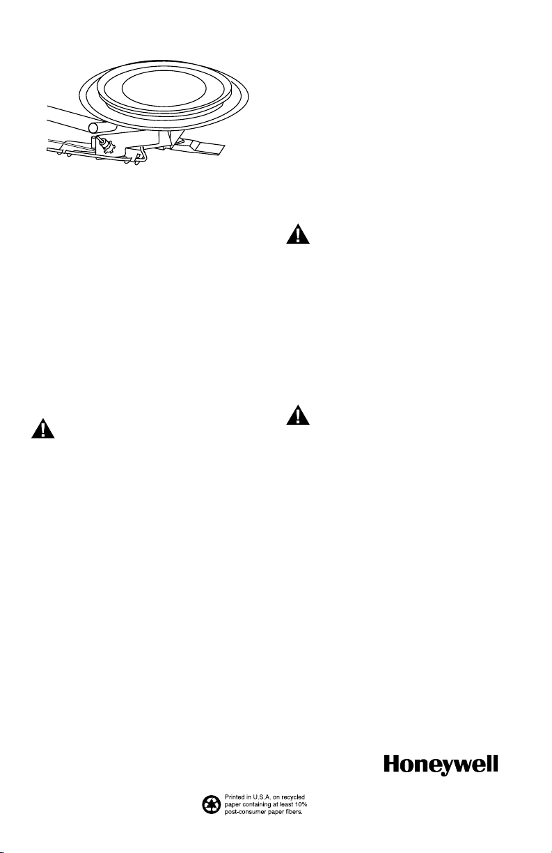
2. Mount the pilot burner on the main burner. See
Fig. 1. Mounting surfaces other than the main
burner can shift, bend, or warp as the water heater
tank expands and contracts during operation.
69-1863-03
Page 2
CS8800 WATER HEATER PILOT BURNER ASSEMBLY
Fig. 1. Mount pilot burner on main burner.
3. Mount the pilot burner so the ignition flame
remains properly positioned with respect to the
main burner flame.
4. Supply the pilot flame with ample air that is free
of combustion products.
5. Do not impinge the pilot flame on adjacent parts.
Do not impinge the main burner flame on the pilot
burner.
6. Do not expose the pilot flame to falling scale that
could impair ignition of the main burner.
7. Do not expose the pilot burner to the main burner
rollout while igniting or extinguishing.
8. Do not expose the pilot flame to drafts that push
or pull the pilot flame away from the thermopile.
M13697
STARTUP AND CHECKOUT
Perform Gas Leak Test
WARNING
Fire or Explosion Hazard.
Can cause property damage, serious injury
or death.
Check for gas leaks with soap and water solution
any time work is done on a gas system.
Gas Leak Test
1. Ensure that the gas supply is turned on at the
appliance service valve.
2. Paint the pipe connections upstream from the pilot
burner with a rich soap and water solution. Bubbles
indicate a gas leak.
3. If a leak is detected, tighten the pipe connections.
4. Stand clear of the main burner while lighting to
prevent injury from hidden leaks that could cause
flashback in the appliance vestibule. Light the main
burner.
5. With the main burner in operation, paint the pipe
joints (including the adapters) and gas control inlet
and outlet with a rich soap and water solution.
6. If another leak is detected, tighten the adapter
screws, joints and pipe connections.
7. Replace the part if the leak cannot be stopped.
Pilot Flame
The pilot flame should envelop 3/8 in. to 1/2 in.
(10 to 13 mm) of the thermopile tip.
Ignite Pilot Burner
1. Before lighting the pilot burner, turn the knob to its
lowest setting. Wait for unburned gas to vent.
WARNING
Explosion or Fire Hazard.
Can cause severe injury, death or property
damage.
LP gas is heavier than air and does not vent
upward. Smell for LP gas next to the floor. If you
smell gas, shut off the main valve in the gas
piping or “ON LP” at the tank. Perform the Gas
Leak Test to recheck the connections.
2. Light the pilot burner according to the appliance
manufacturer instructions.
SERVICE
WARNING
Fire or Explosion Hazard.
Can cause property damage, serious injury
or death.
Perform Gas Leak Test anytime work is done to
the system.
Thermopile Performance
Thermopiles require proper temperature differential
between the hot-junction (tip) and cold-junction (base) to
provide satisfactory operation of millivoltage gas controls.
Thermopiles perform less effectively when exposed to
excessive cold-junction or hot-junction temperatures.
Excessive cold-junction temperatures can be caused by
heat radiation from adjacent surfaces or high ambient air
temperatures. Excessive cold-junction temperatures can
be eliminated by shielding the pilot flame, or construct a
baffle to direct secondary air over the pilot burner base.
Excessive hot-junction temperatures can be eliminated
by proper flame adjustment.
Automation and Control Solutions
Honeywell International Inc. Honeywell Limited-Honeywell Limitée
1985 Douglas Drive North 35 Dynamic Drive
Golden Valley, MN 55422 Toronto, Ontario M1V 4Z9
customer.honeywell.com
® U.S. Registered Trademark
© 2008 Honeywell International Inc.
69-1863—03 M.S. Rev. 07-08
 Loading...