

Page 1

Xenon™ 1900/1902
Preliminary Draft
Area-Imaging Scanner
User’s Guide
™
Page 2

Disclaimer
Preliminary Draft
Honeywell International Inc. (“HII”) reserves the right to make changes in specifications and other information contained in this document without prior notice,
and the reader should in all cases consult HII to determine whether any such
changes have been made. The information in this publication does not represent a commitment on the part of HII.
HII shall not be liable for technical or editorial errors or omissions contained
herein; nor for incidental or consequential damages resulting from the furnishing, performance, or use of this material.
This document contains proprietary information that is protected by copyright.
All rights are reserved. No part of this document may be photocopied, reproduced, or translated into another language without the prior written consent of
HII.
© 2010 Honeywell International Inc. All rights reserved.
Other product names or marks mentioned in this document may be trademarks
or registered trademarks of other companies and are the property of their
respective owners.
Web Address:
Microsoft® Windows®, Windows NT®, Windows 2000, Windows ME, Windows
XP, and the Windows logo are trademarks or registered trademarks of Microsoft
Corporation.
The Bluetooth® word mark and logos are owned by Bluetooth SIG, Inc.
Other product names or marks mentioned in this document may be trademarks
or registered trademarks of other companies and are the property of their
respective owners.
www.honeywellaidc.com
Page 3

Product Agency Compliance - Xenon 1900
Preliminary Draft
USA
FCC Part 15 Subpart B Class B
This device complies with part 15 of the FCC Rules. Operation is subject to
the following two conditions:
1. This device may not cause harmful interference.
2. This device must accept any interference received, including
interference that may cause undesired operation.
This equipment has been tested and found to comply with the limits for a
Class B digital device pursuant to part 15 of the FCC Rules. These limits
are designed to provide reasonable protection against harmful interference
in a residential installation. This equipment generates, uses, and can radiate radio frequency energy and, if not installed and used in accordance
with the instructions, may cause harmful interference to radio communications. However, there is no guarantee that interference will not occur in a
particular installation. If this equipment does cause harmful interference to
radio or television reception, which can be determined by turning the equipment off and on, the user is encouraged to try to correct the interference by
one or more of the following measures:
• Reorient or relocate the receiving antenna.
• Increase the separation between the equipment and receiver.
• Connect the equipment into an outlet on a circuit different from that to
which the receiver is connected.
• Consult the dealer or an experienced radio or television technician for
help.
If necessary, the user should consult the dealer or an experienced radio/
television technician for additional suggestions. The user may find the following booklet helpful: “Something About Interference.” This is available at
FCC local regional offices. Honeywell is not responsible for any radio or
television interference caused by unauthorized modifications of this equipment or the substitution or attachment of connecting cables and equipment
other than those specified by Honeywell. The correction is the responsibility of the user.
Use only shielded data cables with this system.
Caution: Any changes or modifications made to this equipment not
expressly approved by Honeywell may void the FCC authorization to operate this equipment.
UL Statement
UL listed: UL60950-1.
Page 4

Canada
Preliminary Draft
Industry Canada ICES-003
This Class B digital apparatus complies with Canadian ICES-003. Operation is subject to the following conditions:
1. This device may not cause harmful interference.
2. This device must accept any interference received, including
interference that may cause undesired operation.
Conformité à la règlementation canadienne
Cet appareil numérique de la Classe A est conforme à la norme NMB-003
du Canada. Son fonctionnement est assujetti aux conditions suivantes :
1. Cet appareil ne doit pas causer de brouillage préjudiciable.
2. Cet appareil doit pouvoir accepter tout brouillage reçu, y compris le
brouillage pouvant causer un fonctionnement indésirable.
cUL Statement
cUL listed: CSA C22.2 No.60950-1-03.
Europe
The CE marking indicates compliance to 2004/108/EC EMC Directive
with Standards EN55022 CLASS B, EN55024, EN61000-3-2,
EN61000-3-3. In addition, complies to 2006/95/EC Low Voltage Directive, when shipped with recommended power supply.
For further information please contact:
Honeywell International Inc. shall not be liable for use of our product with
equipment (i.e., power supplies, personal computers, etc.) that is not CE
marked and does not comply with the Low Voltage Directive.
Honeywell Imaging & Mobility Europe BV
Nijverheidsweg 9-13
5627 BT Eindhoven
The Netherlands
Waste Electrical and Electronic Equipment
Information
Honeywell complies with Directive 2002/96/EC OF THE EUROPEAN PARLIAMENT AND OF THE COUNCIL of 27 January 2003 on waste electrical
and electronic equipment (WEEE).
This product has required the extraction and use of natural resources for its
production. It may contain hazardous substances that could impact health
and the environment, if not properly disposed.
Page 5

In order to avoid the dissemination of those substances in our environment
Preliminary Draft
and to diminish the pressure on the natural resources, we encourage you to
use the appropriate take-back systems for product disposal. Those systems will reuse or recycle most of the materials of the product you are disposing in a sound way.
The crossed out wheeled bin symbol informs you that the product
should not be disposed of along with municipal waste and invites you to
use the appropriate separate take-back systems for product disposal.
If you need more information on the collection, reuse, and recycling systems, please contact your local or regional waste administration.
You may also contact your supplier for more information on the environmental performances of this product.
Germany
If your product is marked with the GS symbol, then the product
has been issued a GS certificate showing compliance to IEC
60950-1.
Australia/NZ
C-Tick Statement
Conforms to AS/NZS 3548 EMC requirement
Mexico
Conforms to NOM-019.
Russia
Gost-R certificate
Page 6

South Korea
Preliminary Draft
International
Eye Safety Statement: LED
This device has been tested in accordance with IEC60825-1 LED safety,
and has been certified to be a Class 1 LED product.
CB Scheme
Certified to IEC60950-1 (2001) First Edition.
Patents
Please refer to the product packaging for patent information.
Solids and Water Protection
The Xenon 1900 has a rating of IP41, immunity of foreign particles and dripping
water.
Page 7

Product Agency Compliance - Xenon 1902 and
Preliminary Draft
CCB01-010BT Base
USA
FCC Part 15 Subpart C
This device complies with part 15 of the FCC Rules. Operation is subject to
the following two conditions:
1. This device may not cause harmful interference.
2. This device must accept any interference received, including
interference that may cause undesired operation.
Caution: Any changes or modifications made to this equipment
not expressly approved by Honeywell may void the
FCC authorization to operate this equipment.
UL Statement
UL listed: UL60950-1.
Canada
Industry Canada
This device complies with Canadian RSS-210. Operation is subject to the
following conditions:
1. This device may not cause interference.
2. This device must accept any interference, including interference that
may cause undesired operation.
Conformité à la règlementation canadienne
Cet appareil ISM est conforme à la norme CNR-210 du Canada. Son fonctionnement est assujetti aux conditions suivantes :
1. Cet appareil ne doit pas causer de brouillage préjudiciable.
2. Cet appareil doit pouvoir accepter tout brouillage reçu, y compris le
brouillage pouvant causer un fonctionnement indésirable.
Page 8

C-UL Statement
Preliminary Draft
C-UL listed: CSA C22.2 No.60950-1-03 for I.T.E product safety.
Europe
The CE marking on the product indicates that this device is in conformity with all essential requirements of the 1999/5/EC R&TTE Directive.
In addition, complies to 2006/95/EC Low Voltage Directive, when
shipped with recommended power supply. For further information, contact:
Honeywell Imaging & Mobility Europe BV
International Inc.
Nijverheidsweg 9-13
5627 BT Eindhoven
The Netherlands
Honeywell shall not be liable for use of our product with equipment (i.e.,
power supplies, personal computers, etc.) that is not CE marked and does
not comply with the Low Voltage Directive. This equipment is intended for
use throughout the European Community and has been assessed to the
following standards:
EN 300 328
EN 301 489-1
EN 301 489-17
EN60950-1
EN60825-1
Waste Electrical and Electronic Equipment
Information
Honeywell complies with Directive 2002/96/EC OF THE EUROPEAN PARLIAMENT AND OF THE COUNCIL on waste electrical and electronic
equipment (WEEE).
This product has required the extraction and use of natural resources for its
production. It may contain hazardous substances that could impact health
and the environment, if not properly disposed.
In order to avoid the dissemination of those substances in our environment
and to diminish the pressure on the natural resources, we encourage you
to use the appropriate take-back systems for product disposal. Those systems will reuse or recycle most of the materials of the product you are disposing in a sound way.
The crossed out wheeled bin symbol informs you that the product
should not be disposed of along with municipal waste and invites you to
use the appropriate separate take-back systems for product disposal.
Page 9

If you need more information on the collection, reuse, and recycling sys-
!
Preliminary Draft
tems, contact your local or regional waste administration.
You may also contact your supplier for more information on the environ-
mental performances of this product.
Germany
If your product is marked with the GS symbol, then the product
has been issued a GS certificate showing compliance to IEC
60950-1.
Australia/NZ
C-Tick Statement
Conforms to AS/NZS 3548 EMC requirements.
Russia
International
Safety Precautions for Lithium Batteries
• Do not place batteries in fire or heat the batteries.
• Do not store batteries near fire or other high temperature locations.
• Do not store or carry batteries together with metal objects.
• Do not expose batteries to water or allow the batteries to get wet.
• Do not connect (short) the positive and negative terminals, of the
batteries, to each other with any metal object.
• Do not pierce, strike or step on batteries or subject batteries to strong
impacts or shocks.
• Do not disassemble or modify batteries.
Caution:
Danger of explosion if batteries are incorrectly replaced.
Replace only with the same or equivalent type recommended
by the manufacturer. Dispose of used batteries according to
the recycle program for batteries as directed by the governing
agency for the country where the batteries are to be discarded.
Page 10

Eye Safety Statement
Preliminary Draft
LED
This device has been tested in accordance with IEC60825-1:
1993+A1+A2 LED safety, and has been certified to be a Class 1 LED
device.
Radio Technology
Class II
CB Scheme
Certified to CB Scheme IEC 60950-1.
Solids and Water Protection
The Xenon 1902 has a rating of IP41, immunity of foreign particles and
dripping water.
Patents
Refer to product packaging for patent information.
Page 11
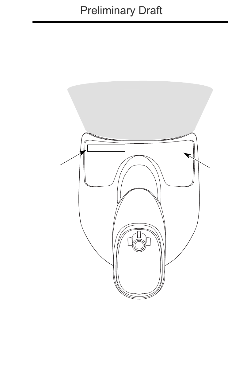
Required Safety Labels
Scanner
Compliance
Label
location
Item
Number, Serial
Number and
Revision
Information
location
Illumination output
Preliminary Draft
Page 12
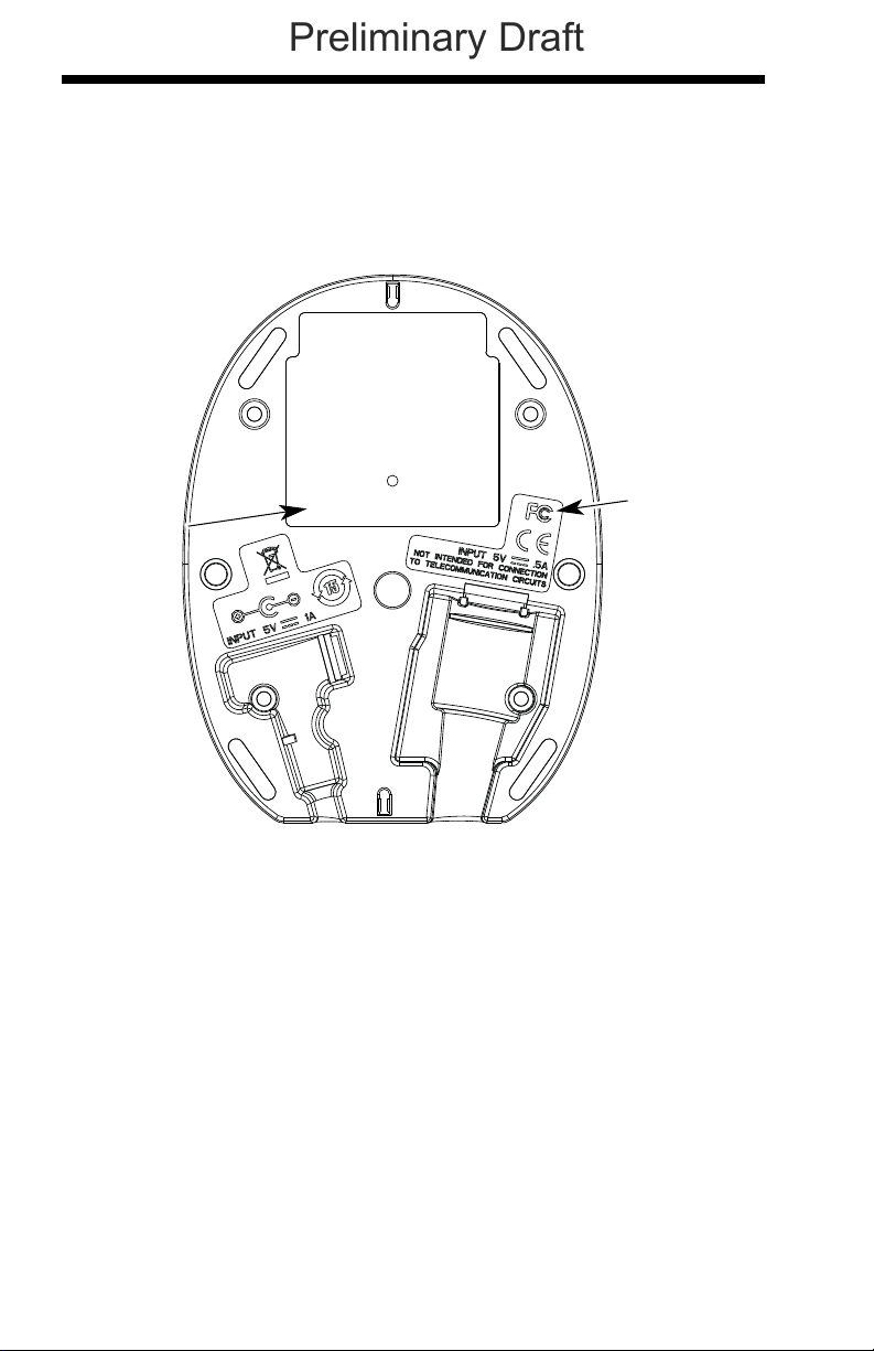
CCB01-010BT Base
Item Number,
Serial
Number and
Revision
Information
location
Compliance
Label
location
Preliminary Draft
Page 13

Table of Contents
Preliminary Draft
Chapter 1 - Getting Started
About This Manual ......................................................1-1
Unpacking Your Device............................................... 1-1
Connecting the Device ................................................ 1-2
Connecting with USB ............................................ 1-2
Connecting with Keyboard Wedge........................ 1-3
Connecting with RS232 Serial Port....................... 1-5
Connecting with RS485......................................... 1-6
Reading Techniques ................................................... 1-8
Menu Bar Code Security Settings ............................... 1-8
Resetting the Factory Defaults.................................... 1-9
Setting Custom Defaults ............................................. 1-9
Resetting the Custom Defaults ................................. 1-10
Chapter 2 - Programming the Interface
Introduction ................................................................. 2-1
Programming the Interface - Plug and Play ................ 2-1
Keyboard Wedge................................................... 2-1
Laptop Direct Connect........................................... 2-1
RS232 Serial Port.................................................. 2-2
RS485 ................................................................... 2-2
RS485 Packet Mode ............................................. 2-3
USB IBM SurePos................................................. 2-4
USB PC or Macintosh Keyboard........................... 2-4
USB HID................................................................ 2-5
USB Serial............................................................. 2-5
Verifone
Gilbarco
Honeywell Bioptic Aux Port Configuration............. 2-7
Datalogic™ Magellan
NCR Bioptic Aux Port Configuration...................... 2-8
Wincor Nixdorf Terminal Default Settings ............. 2-8
®
Ruby Terminal Default Settings ............ 2-6
®
Terminal Default Settings ..................... 2-7
©
Bioptic
Aux Port Configuration..................................... 2-7
i
Page 14

Wincor Nixdorf Beetle™ Terminal
Preliminary Draft
Default Settings................................................2-9
Keyboard Country Layout..........................................2-10
Keyboard Style ..........................................................2-17
Keyboard Conversion ................................................2-18
Control Character Output...........................................2-19
Keyboard Modifiers....................................................2-19
RS232 Baud Rate......................................................2-22
RS232 Word Length: Data Bits, Stop Bits,
and Parity ................................................................2-23
RS232 Receiver Time-Out.........................................2-24
RS232 Handshaking..................................................2-24
RS232 Timeout....................................................2-25
XON/XOFF ..........................................................2-25
ACK/NAK .............................................................2-25
Scanner to Bioptic Communication............................2-26
Scanner-Bioptic Packet Mode .............................2-26
Scanner-Bioptic ACK/NAK Mode......................... 2-27
Scanner-Bioptic ACK/NAK Timeout..................... 2-27
Chapter 3 - Cordless System Operation
How the Cordless Base Works....................................3-1
Linking the Scanner to the Base..................................3-1
Communication Between the Cordless System
and the Host..............................................................3-2
RF (Radio Frequency) Module Operation....................3-2
System Conditions.......................................................3-2
Linking Process .....................................................3-3
Scanner Is Out of Range .......................................3-3
Scanner Is Moved Back Into Range ......................3-3
Out of Range and Back into Range
with Batch Mode On.........................................3-3
Page Button.................................................................3-3
About the Battery.........................................................3-3
Charging Information .............................................3-4
Battery Recommendations ....................................3-4
ii
Page 15

Proper Disposal of the Battery .............................. 3-5
Preliminary Draft
Beeper and LED Sequences and Meaning................. 3-5
Scanner LED Sequences and Meaning ................ 3-6
Base LED Sequences and Meaning ..................... 3-6
Base Power Communication Indicator .................. 3-7
Reset Scanner ............................................................ 3-7
Scanning while in Base Cradle ................................... 3-7
Paging ......................................................................... 3-8
Paging Mode ......................................................... 3-8
Paging Pitch ......................................................... 3-8
Error Indicators............................................................ 3-9
Beeper Pitch - Base Error ..................................... 3-9
Number of Beeps - Base Error.............................. 3-9
Scanner Report ........................................................... 3-9
Scanner Address....................................................... 3-10
Base Address............................................................ 3-10
Single Scanner Modes .............................................. 3-10
Charge Only Mode .............................................. 3-10
Linked Modes...................................................... 3-11
Unlinking the Scanner ............................................... 3-11
Override Locked Scanner.................................... 3-12
Out-of-Range Alarm .................................................. 3-12
Alarm Sound Type............................................... 3-12
Flexible Power Management..................................... 3-13
Batch Mode ............................................................... 3-14
Batch Mode Beep................................................ 3-15
Batch Mode Storage............................................ 3-15
Batch Mode Quantity........................................... 3-16
Batch Mode Output Order ................................... 3-18
Delete Last Code................................................. 3-18
Clear All Codes ................................................... 3-18
Transmit Records to Host.................................... 3-19
Batch Mode Transmit Delay................................ 3-19
Multiple Scanner Operation....................................... 3-19
Scanner Name .......................................................... 3-20
Application Work Groups .......................................... 3-22
Application Work Group Selection....................... 3-23
iii
Page 16

Resetting the Factory Defaults:
Preliminary Draft
All Application Work Groups....................................3-23
Resetting the Custom Defaults:
All Application Work Groups....................................3-24
Using the Scanner with Bluetooth Devices................3-24
PCs/Laptops ........................................................3-24
PDAs/Mobility Systems Devices.......................... 3-25
Changing the Scanner’s Bluetooth PIN Code...... 3-25
Minimizing Bluetooth/ISM Band Network Activity ......3-25
Auto Reconnect Mode .........................................3-26
Maximum Link Attempts ......................................3-27
Relink Time-Out...................................................3-27
Bluetooth/ISM Network Activity Examples........... 3-28
Host Command Acknowledgment .............................3-29
Chapter 4 - Input/Output Settings
Power Up Beeper ........................................................4-1
Beep on BEL Character...............................................4-1
Trigger Click.................................................................4-2
Good Read and Error Indicators..................................4-2
Beeper – Good Read............................................. 4-2
Beeper Volume – Good Read................................ 4-3
Beeper Pitch – Good Read.................................... 4-3
Beeper Pitch – Error ..............................................4-4
Beeper Duration – Good Read ..............................4-4
LED – Good Read .................................................4-4
Number of Beeps – Good Read ............................4-5
Number of Beeps – Error....................................... 4-5
Good Read Delay ..................................................4-6
User-Specified Good Read Delay.......................... 4-6
Manual/Serial Trigger Modes.......................................4-6
Manual Trigger....................................................... 4-6
Serial Trigger .........................................................4-7
In-Stand Sensor Mode.................................................4-8
Presentation Mode.......................................................4-9
Presentation LED Behavior after Decode.............. 4-9
iv
Page 17

Presentation Sensitivity....................................... 4-10
Preliminary Draft
Streaming Presentation™ Mode ............................... 4-10
Mobile Phone Read Mode......................................... 4-11
Image Snap and Ship................................................ 4-11
Hands Free Time-Out ............................................... 4-11
Reread Delay ............................................................ 4-12
User-Specified Reread Delay.................................... 4-12
Illumination Lights ..................................................... 4-13
Aimer Delay............................................................... 4-13
User-Specified Aimer Delay ................................ 4-13
Scanner Time-Out..................................................... 4-14
Aimer Mode............................................................... 4-14
Centering................................................................... 4-14
Preferred Symbology ................................................ 4-16
High Priority Symbology...................................... 4-17
Low Priority Symbology....................................... 4-17
Preferred Symbology Time-out ........................... 4-17
Preferred Symbology Default .............................. 4-18
Output Sequence Overview ......................................4-18
Require Output Sequence................................... 4-18
Output Sequence Editor...................................... 4-18
To Add an Output Sequence............................... 4-19
Other Programming Selections ........................... 4-19
Output Sequence Editor...................................... 4-21
Partial Sequence................................................. 4-21
Require Output Sequence................................... 4-22
Multiple Symbols ....................................................... 4-22
No Read .................................................................... 4-23
Video Reverse........................................................... 4-23
Chapter 5 - Data Editing
Prefix/Suffix Overview ................................................. 5-1
To Add a Prefix or Suffix: ...................................... 5-1
To Clear One or All Prefixes or Suffixes................ 5-2
To Add a Carriage Return Suffix
to All Symbologies ........................................... 5-3
v
Page 18

Prefix Selections..........................................................5-3
Preliminary Draft
Suffix Selections ..........................................................5-4
Function Code Transmit ..............................................5-4
Intercharacter, Interfunction,
and Intermessage Delays..........................................5-4
Intercharacter Delay ..............................................5-5
User Specified Intercharacter Delay ......................5-5
Interfunction Delay.................................................5-6
Intermessage Delay............................................... 5-6
Chapter 6 - Data Formatting
Data Format Editor Introduction...................................6-1
To Add a Data Format .................................................6-1
Other Programming Selections.............................. 6-3
Terminal ID Table ........................................................6-4
Data Format Editor Commands...................................6-4
Move Commands................................................... 6-5
Search Commands ................................................6-6
Miscellaneous Commands..................................... 6-7
Data Formatter.............................................................6-8
Data Format Non-Match Error Tone ......................6-9
Primary/Alternate Data Formats ................................6-10
Single Scan Data Format Change .......................6-10
Chapter 7 - Symbologies
All Symbologies ...........................................................7-2
Message Length Description .......................................7-2
Codabar.......................................................................7-3
Codabar Concatenation......................................... 7-4
Code 39 .......................................................................7-6
Code 32 Pharmaceutical (PARAF) ........................7-8
Full ASCII............................................................... 7-9
Code 39 Code Page ..............................................7-9
Interleaved 2 of 5.......................................................7-10
NEC 2 of 5 .................................................................7-12
Code 93 .....................................................................7-14
vi
Page 19

Code 93 Code Page............................................ 7-14
Preliminary Draft
Straight 2 of 5 Industrial (three-bar start/stop) .......... 7-15
Straight 2 of 5 IATA (two-bar start/stop).................... 7-16
Matrix 2 of 5 .............................................................. 7-17
Code 11..................................................................... 7-18
Code 128................................................................... 7-19
ISBT 128 Concatenation ..................................... 7-19
Code 128 Code Page.......................................... 7-20
GS1-128.................................................................... 7-21
Telepen ..................................................................... 7-22
UPC-A ....................................................................... 7-23
UPC-A/EAN-13
with Extended Coupon Code .................................. 7-25
UPC-E0 ..................................................................... 7-26
UPC-E1 ..................................................................... 7-29
EAN/JAN-13.............................................................. 7-29
ISBN Translate.................................................... 7-31
EAN/JAN-8................................................................ 7-32
MSI............................................................................ 7-34
GS1 DataBar Omnidirectional................................... 7-36
GS1 DataBar Limited ................................................ 7-36
GS1 DataBar Expanded............................................ 7-37
Trioptic Code............................................................. 7-38
Codablock A.............................................................. 7-38
Codablock F .............................................................. 7-40
PDF417 ..................................................................... 7-41
MicroPDF417 ............................................................ 7-42
GS1 Composite Codes ............................................. 7-43
UPC/EAN Version ............................................... 7-43
GS1 Emulation .......................................................... 7-44
TCIF Linked Code 39 (TLC39).................................. 7-45
QR Code ................................................................... 7-45
Data Matrix................................................................ 7-47
MaxiCode .................................................................. 7-48
Aztec Code................................................................ 7-49
Chinese Sensible (Han Xin) Code ............................ 7-50
Postal Codes - 2D ..................................................... 7-51
vii
Page 20

Single 2D Postal Codes:...................................... 7-51
Preliminary Draft
Combination 2D Postal Codes:............................ 7-52
Postal Codes - Linear ................................................7-54
China Post (Hong Kong 2 of 5)............................ 7-54
Korea Post ...........................................................7-56
Chapter 8 - Imaging Commands
Single-Use Basis .........................................................8-1
Command Syntax ........................................................8-1
Image Snap - IMGSNP................................................8-2
IMGSNP Modifiers .................................................8-2
Image Ship - IMGSHP .................................................8-5
IMGSHP Modifiers .................................................8-5
Intelligent Signature Capture - IMGBOX....................8-14
Signature Capture Optimize ................................8-14
IMGBOX Modifiers...............................................8-15
RF Default Imaging Device........................................8-19
Chapter 9 - Interface Keys
Keyboard Function Relationships................................9-1
Supported Interface Keys ............................................9-3
Chapter 10 - Utilities
To Add a Test Code I.D. Prefix to All Symbologies ...10-1
Show Decoder Revision ............................................10-1
Show Scan Driver Revision .......................................10-1
Show Software Revision............................................10-1
Show Data Format.....................................................10-2
Test Menu..................................................................10-2
TotalFreedom ............................................................10-2
Application Plug-Ins (Apps) .......................................10-3
EZConfig Introduction................................................10-3
Installing EZConfig from the Web ........................10-4
viii
Page 21

Chapter 11 - Serial Programming Commands
Preliminary Draft
Conventions .............................................................. 11-1
Menu Command Syntax............................................ 11-1
Query Commands ..................................................... 11-2
Responses .......................................................... 11-3
Trigger Commands ................................................... 11-4
Resetting the Standard Product Defaults.................. 11-4
Menu Commands...................................................... 11-5
Chapter 12 - Product Specifications
1900 Scanner Product Specifications ....................... 12-1
1902 Scanner Product Specifications ....................... 12-2
CCB01-010BT Charge Base Product Specifications 12-3
Standard Cable Pinouts ............................................ 12-4
Keyboard Wedge................................................. 12-4
Serial Output ...................................................... 12-5
RS485 Output ..................................................... 12-6
USB..................................................................... 12-7
Chapter 13 - Maintenance
Repairs...................................................................... 13-1
Maintenance.............................................................. 13-1
Cleaning the Device ............................................ 13-1
Inspecting Cords and Connectors....................... 13-1
Replacing Cables in Corded Scanners .....................13-1
Replacing an Interface Cable.............................. 13-2
Replacing Cables and Batteries
in Cordless Systems ............................................... 13-2
Replacing an Interface Cable in a Base.............. 13-2
Changing a scanner Battery................................ 13-3
Troubleshooting a Xenon Scanner............................ 13-3
Troubleshooting a Cordless System ......................... 13-4
Troubleshooting a Base ...................................... 13-4
Troubleshooting a Cordless Scanner.................. 13-5
ix
Page 22

Chapter 14 - Customer Support
Preliminary Draft
Appendix A - Reference Charts
Symbology Chart ........................................................ A-1
ASCII Conversion Chart (Code Page 1252)............... A-4
Code Page Mapping of Printed Barcodes .................. A-6
x
Page 23

1
Preliminary Draft
Getting Started
About This Manual
This User’s Guide provides installation and programming instructions for the
Xenon™ 1900 and 1902 area-imaging scanners. Product specifications,
dimensions, warranty, and customer support information are also included.
Honeywell bar code scanners are factory programmed for the most common
terminal and communications settings. If you need to change these settings,
programming is accomplished by scanning the bar codes in this guide.
An asterisk (*) next to an option indicates the default setting.
Unpacking Your Device
After you open the shipping carton containing the product, take the following
steps:
• Check for damage during shipment. Report damage immediately to the
carrier who delivered the carton.
• Make sure the items in the carton match your order.
• Save the shipping container for later storage or shipping.
1 - 1
Page 24
Connecting the Device
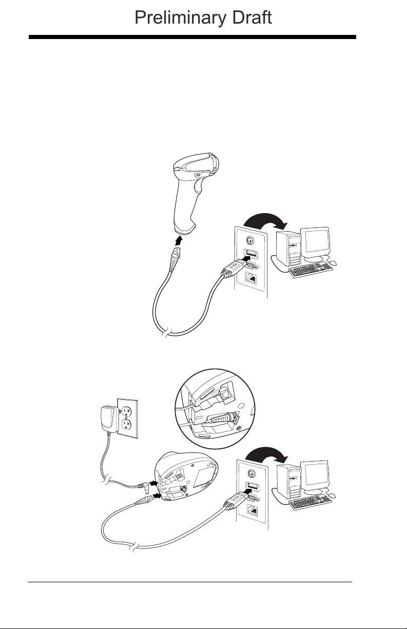
Corded Scanner USB
Connection:
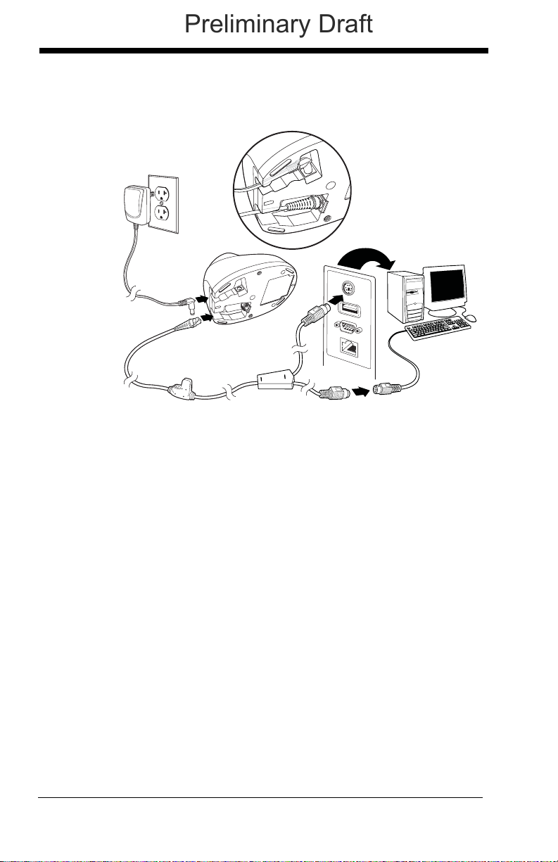
Cordless Base USB
Connection:
Preliminary Draft
Connecting with USB
A scanner or a cordless base can be connected to the USB port of a computer.
1. Connect the appropriate interface cable to the device first, then to the
computer.
1 - 2
Page 25
2. Make sure the cables are secured in the wireways in the bottom of the
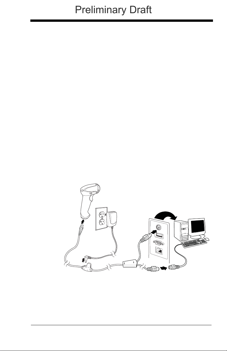
Corded Scanner
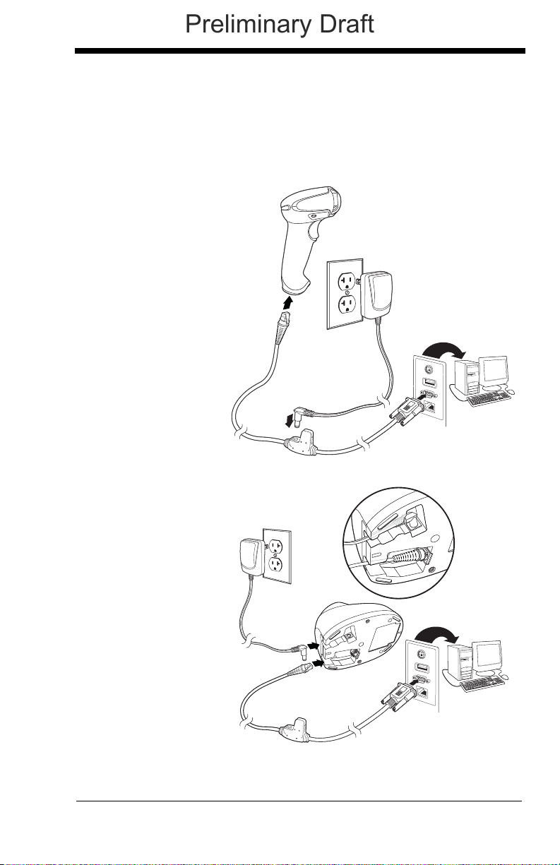
Keyboard Wedge
Connection:
Preliminary Draft
cordless base and that the base sits flat on a horizontal surface.
3. The scanner beeps.
4. Verify the scanner or cordless base operation by scanning a bar code
from the Sample Symbols in the back of this manual.
The unit defaults to a USB PC Keyboard. Refer to page 2-4 for other USB
terminal settings.
For additional USB programming and technical information, refer to “USB
Application Note,” available at www.honeywellaidc.com.
Connecting with Keyboard Wedge
A scanner or cordless base can be connected between the keyboard and
PC as a “keyboard wedge,” plugged into the serial port, or connected to a
portable data terminal in wand emulation or non decoded output mode.
The following is an example of a keyboard wedge connection:
1. Turn off power and disconnect the keyboard cable from the back of the
terminal/computer.
2. Connect the appropriate interface cable to the device and to the
terminal/computer.
1 - 3
Page 26
3. Make sure the cables are secured in the wireways in the bottom of the
Cordless Base
Keyboard Wedge
Connection:
Preliminary Draft
cordless base and that the base sits flat on a horizontal surface.
4. Turn the terminal/computer power back on. The scanner beeps.
5. Verify the scanner or cordless base operation by scanning a bar code
from the Sample Symbols in the back of this manual. The scanner
beeps once.
The unit defaults to an IBM PC AT and compatibles keyboard wedge interface with a USA keyboard. A carriage return (CR) suffix is added to bar
code data.
1 - 4
Page 27
Connecting with RS232 Serial Port
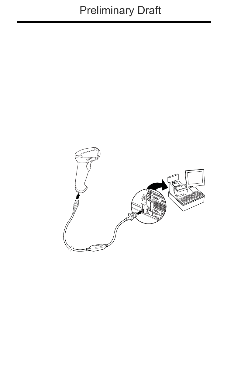
Corded Scanner
RS232 Serial Port
Connection:
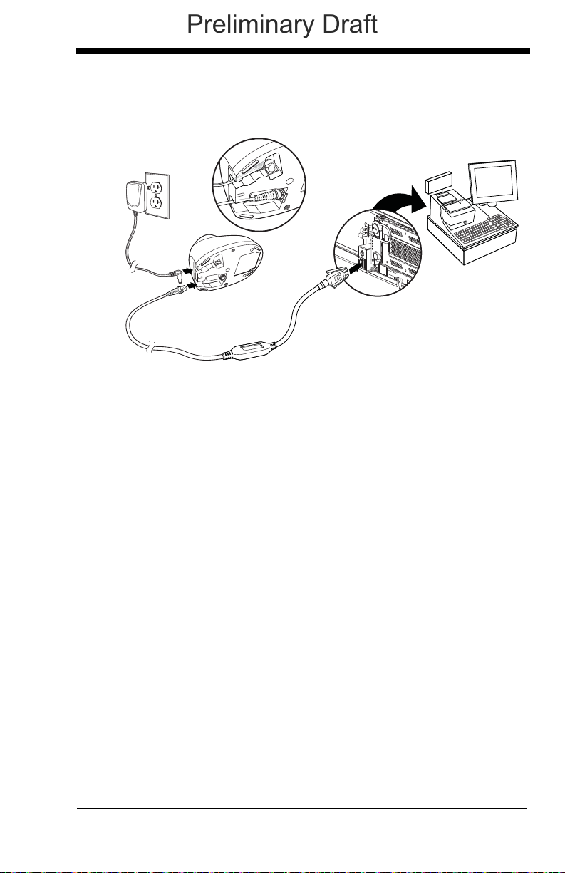
Cordless Base
RS232 Serial Port
Connection:
Preliminary Draft
1. Turn off power to the terminal/computer.
2. Connect the appropriate interface cable to the scanner.
Note: For the scanner or cordless base to work properly, you must have the
correct cable for your type of terminal/computer.
1 - 5
Page 28
3. Make sure the cables are secured in the wireways in the bottom of the
Corded Scanner
RS485
Connection:
Preliminary Draft
cordless base and that the base sits flat on a horizontal surface.
4. Plug the serial connector into the serial port on your computer.
Tighten the two screws to secure the connector to the port.
5. Once the scanner or cordless base has been fully connected, power
up the computer.
This interface programs 115,200 baud, 8 data bits, no parity, and 1 stop bit.
Connecting with RS485
A scanner or cordless base can be connected for an IBM POS terminal
interface
1. Connect the appropriate interface cable to the device, then to the computer.
1 - 6
Page 29
2. Make sure the cables are secured in the wireways in the bottom of the
Cordless Base
RS485
Connection:
Preliminary Draft
cordless base and that the base sits flat on a horizontal surface.
3. Turn the terminal/computer power back on. The scanner beeps.
4. Verify the scanner or cordless base operation by scanning a bar code
from the Sample Symbols in the back of this manual. The scanner
beeps once.
For further RS485 settings, refer to RS485, page 2-2..
1 - 7
Page 30
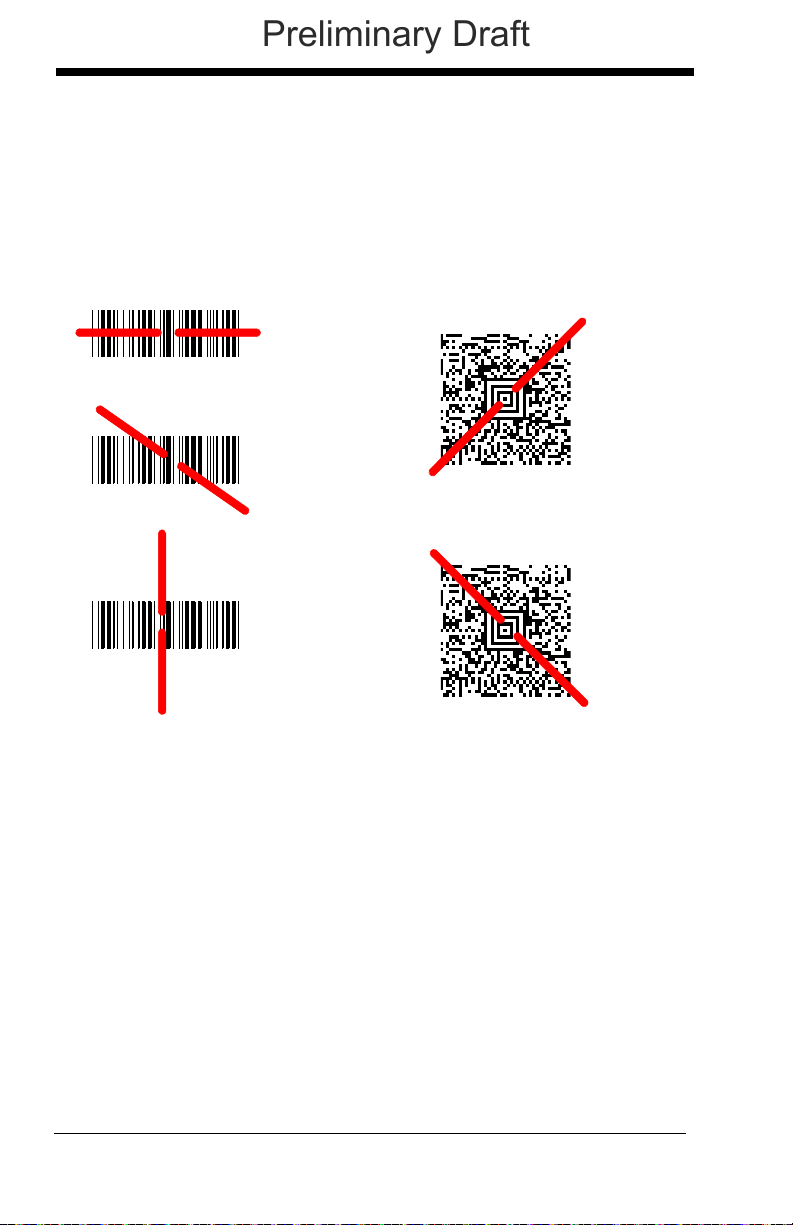
Reading Techniques
Linear bar code 2D Matrix symbol
Preliminary Draft
The scanner has a view finder that projects a bright red aiming beam that corresponds to the scanner’s horizontal field of view. The aiming beam should be
centered over the bar code, but it can be positioned in any direction for a good
read.
The aiming beam is smaller when the scanner is closer to the code and larger
when it is farther from the code. Symbologies with smaller bars or elements
(mil size) should be read closer to the unit. Symbologies with larger bars or elements (mil size) should be read farther from the unit. To read single or multiple
symbols (on a page or on an object), hold the scanner at an appropriate distance from the target, pull the trigger, and center the aiming beam on the symbol. If the code being scanned is highly reflective (e.g., laminated), it may be
necessary to tilt the code up 15° to 18° to prevent unwanted reflection.
Menu Bar Code Security Settings
Honeywell scanners are programmed by scanning menu bar codes or by sending serial commands to the scanner. If you want to restrict the ability to scan
menu codes, you can use the Menu Bar Code Security settings. Please contact
the nearest technical support office (see Technical Assistance on page 14-1)
for further information.
1 - 8
Page 31

Resetting the Factory Defaults
Restore Factory Defaults
Save Defaults
Preliminary Draft
If you aren’t sure what programming options are in your scanner, or you’ve
changed some options and want the factory default settings restored, first scan
the Restore Factory Defaults bar code, then scan Save Defaults. This resets
the scanner to the factory defaults.
Note: If using a cordless system, scanning the Save Defaults bar code also
causes both the scanner and the base to perform a reset and become
unlinked. The scanner must be placed in its base to re-establish the link
before any setup codes are entered. See Cordless System
Operation beginning on page 3-1 for additional information.
The Menu Commands, beginning on page 11-5 list the factory default settings
for each of the commands (indicated by an asterisk (*) on the programming
pages).
Setting Custom Defaults
You have the ability to create a set of menu commands as your own, custom
defaults. To do so, scan the Set Custom Defaults bar code below before each
menu command or sequence you want saved. If your command requires scanning numeric codes from the back cover, then a Save code, that entire
sequence will be saved to your custom defaults. Scan the Set Custom
Defaults code again before the next command you want saved to your custom
defaults.
1 - 9
Page 32

When you have entered all the commands you want to save for your custom
Save Custom Defaults
Set Custom Defaults
Custom Product Default Settings:
Current Application Group
Preliminary Draft
defaults, scan the Save Custom Defaults bar code.
Note: If using a cordless system, scanning the Save Defaults bar code also
causes both the scanner and the base to perform a reset and become
unlinked. The scanner must be placed in its base to re-establish the link
before any setup codes are entered. See Cordless System
Operation beginning on page 3-1 for additional information.
You may have a series of custom settings and want to correct a single setting.
To do so, just scan the new setting to overwrite the old one. For example, if you
had previously saved the setting for Beeper Volume at Low to your custom
defaults, and decide you want ithe beeper volume set to High, just scan the Set
Custom Defaults bar code, then scan the Beeper Volume High menu code,
and then Save Custom Defaults. The rest of the custom defaults will remain,
but the beeper volume settiing will be updated.
Resetting the Custom Defaults
If you want the custom default settings restored to your scanner, scan the Custom Product Default Settings bar code below. This resets the scanner to the
custom defaults. If there are no custom defaults, it will reset the scanner to the
factory defaults. Any settings that have not been specified through the custom
defaults will be defaulted to the factory default settings.
Note: If using a cordless system, scanning this bar code also causes both the
scanner and the base to perform a reset and become unlinked. The
scanner must be placed in its base to re-establish the link. See Cordless
System Operation beginning on page 3-1 for additional information.
1 - 10
Page 33

2
IBM PC AT and Compatibles with
CR suffix
Laptop Direct Connect
with CR suffix
Preliminary Draft
Programming the Interface
Introduction
This chapter describes how to program your system for the desired interface.
Programming the Interface - Plug and Play
Plug and Play bar codes provide instant scanner set up for commonly used
interfaces.
Note: After you scan one of the codes, power cycle the host terminal to have
the interface in effect.
Keyboard Wedge
If you want your system programmed for an IBM PC AT and compatibles
keyboard wedge interface with a USA keyboard, scan the bar code below.
Keyboard wedge is the default interface.
Note: The following bar code also programs a carriage return (CR) suffix.
Laptop Direct Connect
For most laptops, scanning the Laptop Direct Connect bar code allows
operation of the scanner in parallel with the integral keyboard. The following Laptop Direct Connect bar code also programs a carriage return (CR)
suffix and turns on Emulate External Keyboard (page 2-18).
2 - 1
Page 34
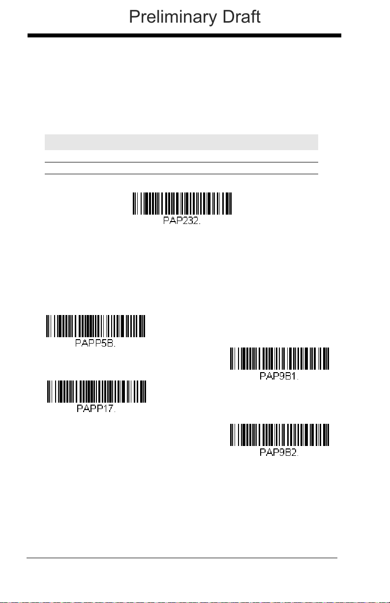
RS232 Serial Port
RS232 Interface
IBM Port 5B Interface
IBM Port 9B
HHBCR-1 Interface
IBM Port 17 Interface
IBM Port 9B
HHBCR-2 Interface
Preliminary Draft
The RS232 Interface bar code is used when connecting to the serial port
of a PC or terminal. The following RS232 Interface bar code also programs a carriage return (CR) and a line feed (LF) suffix, baud rate, and
data format as indicated below. It also changes the trigger mode to man-
ual.
Option Setting
Baud Rate 115,200 bps
Data Format 8 data bits, no parity bit, 1 stop bit
RS485
Scan one of the following “Plug and Play” codes to program the scanner for
an IBM POS terminal interface.
Note: After scanning one of these codes, you must power cycle the cash
register.
2 - 2
Page 35

Each bar code above also programs the following suffixes for each symbol-
Packet Mode On
* Packet Mode Off
Packet Length
Preliminary Draft
ogy:
Symbology Suffix Symbology Suffix
EAN 8 0C Code 39 00 0A 0B
EAN 13 16 Interleaved 2 of 5 00 0D 0B
UPC A 0D Code 128 * 00 0A 0B
UPC E 0A Code 128 ** 00 18 0B
* Suffixes programmed for Code 128 with IBM 4683 Port 5B, IBM 4683 Port 9B
HHBCR-1, and IBM 4683 Port 17 Interfaces
**Suffixes programmed for Code 128 with IBM 4683 Port 9 HHBCR-2 Interface
RS485 Packet Mode
The following selection allows you to break up large bar code data into
smaller packets on an IBM POS terminal. To break up large bar codes into
small packets, scan the Packet Mode On bar code below. Scan the Packet
Mode Off bar code if you want large bar code data to be sent to the host in
a single chunk.
Default = Packet Mode Off.
RS485 Packet Length
If you are using Packet mode, you can specify the size of the data
“packet” that is sent to the host. Scan the Packet Length bar code,
then then the packet size (from 20 - 256) from the Programming Chart
inside the back cover of this manual, then Save.
Default = 40
.
2 - 3
Page 36

USB IBM SurePos
USB IBM SurePos
(USB Handheld Scanner)
Interface
USB IBM SurePos
(USB Tabletop Scanner)
Interface
U
S
B
K
e
y
b
o
a
r
d
(
P
C
)
USB Keyboard (Mac)
USB Japanese Keyboard (PC)
Preliminary Draft
Scan one of the following “Plug and Play” codes to program the scanner for
an IBM SurePos (USB handheld scanner) or IBM SurePos (USB tabletop
scanner) interface.
Note: After scanning one of these codes, you must power cycle the cash
register.
Each bar code above also programs the following suffixes for each symbology:
Symbology Suffix Symbology Suffix
EAN 8 0C Code 39 00 0A 0B
EAN 13 16 Interleaved 2 of 5 00 0D 0B
UPC A 0D Code 128 00 18 0B
UPC E 0A Code 39 00 0A 0B
USB PC or Macintosh Keyboard
Scan one of the following codes to program the scanner for USB PC Keyboard or USB Macintosh Keyboard. Scanning these codes also adds a CR
and LF.
2 - 4
Page 37

USB HID
USB HID Bar Code Scanner
USB Serial
CTS/RTS Emulation On
* CTS/RTS Emulation Off
Preliminary Draft
Scan the following code to program the scanner for USB HID bar code
scanners.
USB Serial
Scan the following code to program the scanner to emulate a regular
RS232-based COM Port. If you are using a Microsoft® Windows® PC, you
will need to download a driver from the Honeywell website
(www.honeywellaidc.com). The driver will use the next available COM Port
number. Apple® Macintosh computers recognize the scanner as a USB
CDC class device and automatically uses a class driver.
Note: No extra configuration (e.g., baud rate) is necessary.
CTS/RTS Emulation
2 - 5
Page 38

ACK/NAK Mode
ACK/NAK Mode On
* ACK/NAK Mode Off
Verifone Ruby Settings
Preliminary Draft
Verifone® Ruby Terminal Default Settings
Scan the following Plug and Play code to program the scanner for a Verifone Ruby terminal. This bar code sets the baud rate to 1200 bps and the
data format to 8 data bits, no parity bit, 1 stop bit. It also also adds a line
feed (LF) suffix and programs the following prefixes for each symbology:
Symbology Prefix
UPC-A A
UPC-E A
EAN-8 FF
EAN-13 F
2 - 6
Page 39
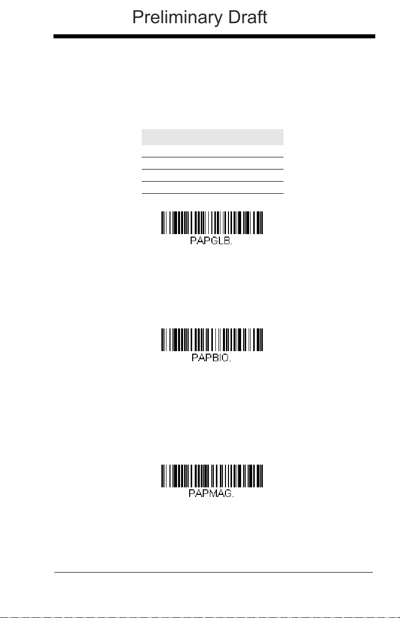
Gilbarco® Terminal Default Settings
Gilbarco Settings
Honeywell Bioptic Settings
Datalogic Magellan Bioptic Settings
Preliminary Draft
Scan the following Plug and Play code to program the scanner for a Gilbarco terminal. This bar code sets the baud rate to 2400 bps and the data
format to 7 data bits, even parity, 2 stop bits. It also also adds a carriage
return (CR) suffix and programs the following prefixes for each symbology:
Symbology Prefix
UPC-A A
UPC-E E0
EAN-8 FF
EAN-13 F
Honeywell Bioptic Aux Port Configuration
Scan the following Plug and Play code to program the scanner for a Honeywell bioptic scanner auxiliary port configuration. This bar code sets the
baud rate to 38400 bps and the data format to 8 data bits, no parity, 1 stop
bit.
Datalogic™ Magellan© Bioptic Aux Port Configuration
Scan the following Plug and Play code to program the scanner for a Datalogic Magellan bioptic scanner auxiliary port configuration. This bar code
sets the baud rate to 9600 bps and the data format to 8 data bits, no parity,
1 stop bit.
2 - 7
Page 40

NCR Bioptic Aux Port Configuration
NCR Bioptic Settings
Wincor Nixdorf Terminal Settings
Preliminary Draft
Scan the following Plug and Play code to program the scanner for an NCR
bioptic scanner auxiliary port configuration. The following prefixes are programmed for each symbology:
Symbology Prefix Symbology Prefix
UPC-A A Code 39 B1
UPC-E E0 Interleaved 2 of 5 B2
EAN-8 FF All other bar
codes
EAN-13 F
B3
Wincor Nixdorf Terminal Default Settings
Scan the following Plug and Play code to program the scanner for a Wincor
Nixdorf terminal. This bar code sets the baud rate to 9600 bps and the
data format to 8 data bits, no parity, 1 stop bit.
2 - 8
Page 41

Wincor Nixdorf Beetle™ Terminal Default Settings
Wincor Nixdorf Beetle Settings
Preliminary Draft
Scan the following Plug and Play code to program the scanner for a Wincor
Nixdorf Beetle terminal. The following prefixes are programmed for each
symbology:
Symbology Prefix Symbology Prefix
Code 128 K EAN-13 A
Code 93 L GS1-128 P
Codabar N Interleaved 2 of 5 I
UPC-A A0 Plessey O
UPC-E C Straight 2 of 5 IATA H
EAN-8 B All other bar codes M
2 - 9
Page 42
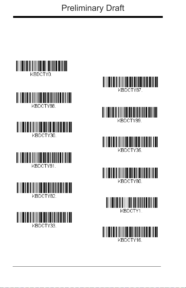
Keyboard Country Layout
* United States
United States (Dvorak left)
United States (International)
Albania
Azeri (Cyrillic)
Azeri (Latin)
Belarus
Belgium
United States (Dvorak)
United States (Dvorak right)
Bosnia
Brazil
Preliminary Draft
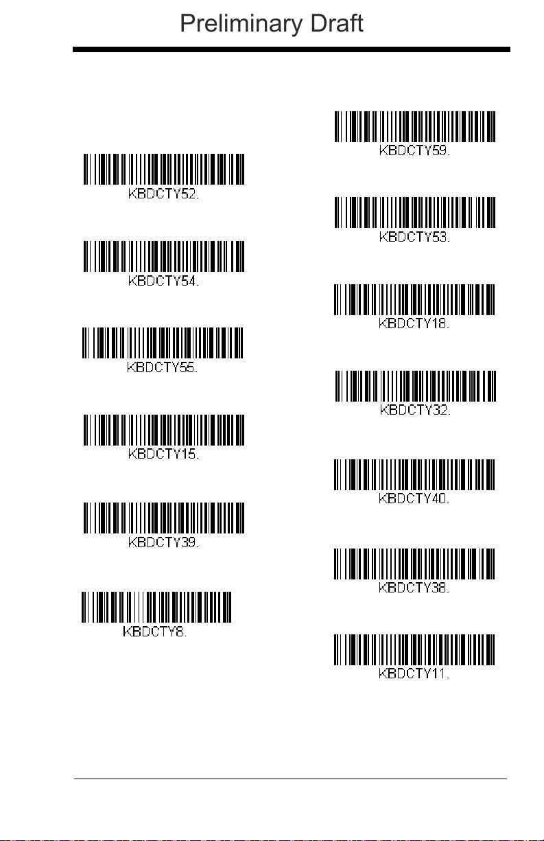
Scan the appropriate country code below to program the keyboard layout for
your country or language. As a general rule, the following characters are supported, but need special care for countries other than the United States:
@ | $ # { } [ ] = / ‘ \ < > ~
2 - 10
Page 43
Keyboard Country (continued)
Bulgaria (Latin)
Canada (French)
Canada (Multilingual)
Croatia
Czech
Czech (Programmers)
Czech (QWERTY)
Czech (QWERTZ)
Bulgaria (Cyrillic)
Canada (French legacy)
Brazil (MS)
Denmark
Dutch (Netherlands)
Preliminary Draft
2 - 11
Page 44

Keyboard Country (continued)
Finland
Gaelic
Germany
Greek
Greek (220 Latin)
Greek (220)
Greek (319 Latin)
Greek (319)
Faeroese
France
Estonia
Greek (Latin)
Greek (MS)
Preliminary Draft
2 - 12
Page 45

Keyboard Country (continued)
Italian (142)
Hungarian (101 key)
Iceland
Irish
Italy
Japan ASCII
Kazakh
Kyrgyz (Cyrillic)
Hebrew
Hungary
Greek (Polytonic)
Latin America
Latvia
Preliminary Draft
2 - 13
Page 46

Keyboard Country (continued)
Lithuania (IBM)
Malta
Mongolian (Cyrillic)
Norway
Poland
Polish (214)
Polish (Programmers)
Portugal
Lithuania
Macedonia
Latvia (QWERTY)
Romania
Russia
Preliminary Draft
2 - 14
Page 47

Keyboard Country (continued)
SCS
Serbia (Latin)
Slovakia
Slovakia (QWERTY)
Slovakia (QWERTZ)
Slovenia
Spain
Spanish variation
Russian (Typewriter)
Serbia (Cyrillic)
Russian (MS)
Sweden
Switzerland (French)
Preliminary Draft
2 - 15
Page 48

Keyboard Country (continued)
Turkey F
Ukrainian
United Kingdom
United Stated (Dvorak right)
United States (Dvorak left)
United States (Dvorak)
United States (International)
Uzbek (Cyrillic)
Tatar
Turkey Q
Switzerland (German)
Preliminary Draft
Refer to the Honeywell website (www.honeywell.com/aidc) for complete keyboard country support information and applicable interfaces. If you need to program a keyboard for a country other than one listed above, scan the Program
Keyboard Country bar code below, then scan the numeric bar code(s) for the
2 - 16
Page 49

appropriate country from the inside back cover, then the Save bar code.
Program Keyboard Country
* Regular
Caps Lock
Shift Lock
Automatic Caps Lock
Preliminary Draft
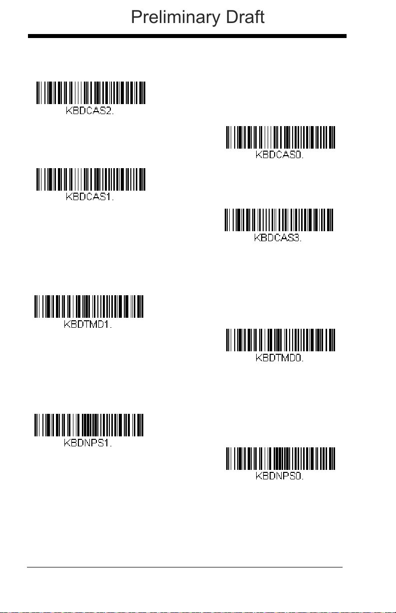
Keyboard Style
This programs keyboard styles, such as Caps Lock and Shift Lock. If you have
used Keyboard Conversion settings, they will override any of the following Keyboard Style settings.
Regular is used when you normally have the Caps Lock key off.
Caps Lock
Shift Lock
to U.S. keyboards).
is used when you normally have the Caps Lock key on.
is used when you normally have the Shift Lock key on (not common
Default = Regular.
Automatic Caps Lock is used if you change the Caps Lock key on and off.
The software tracks and reflects if you have Caps Lock on or off . This selection
can only be used with systems that have an LED that notes the Caps Lock status (AT keyboards).
2 - 17
Page 50

Autocaps via NumLock bar code should be scanned in countries (e.g., Ger-
Autocaps via NumLock
Emulate External Keyboard
* Keyboard Conversion Off
Convert All Characters
to Upper Case
Convert All Characters
to Lower Case
Preliminary Draft
many, France) where the Caps Lock key cannot be used to toggle Caps Lock.
The NumLock option works similarly to the regular Autocaps, but uses the NumLock key to retrieve the current state of the Caps Lock.
Emulate External Keyboard should be scanned if you do not have an external
keyboard (IBM AT or equivalent).
Note: After scanning the Emulate External Keyboard bar code, you must power
cycle your computer.
Keyboard Conversion
Alphabetic keyboard characters can be forced to be all upper case or all lowercase. So if you have the following bar code: “abc569GK,” you can make the
output “ABC569GK” by scanning Convert All Characters to Upper Case, or to
“abc569gk” by scanning Convert All Characters to Lower Case.
These settings override Keyboard Style selections.
Note: If your interface is a keyboard wedge, first scan the menu code for
Automatic Caps Lock (page 2-17). Otherwise, your ouput may not be as
expected.
Default = Keyboard Conversion Off
2 - 18
.
Page 51

Control Character Output
Control Character Output On
* Control Character Output Off
Preliminary Draft
This selection sends a text string instead of a control character. For example,
when the control character for a carriage return is expected, the output would
display [CR] instead of the ASCII code of 0D. Refer to ASCII Conversion Chart
(Code Page 1252) on page A-4. Only codes 00 through 1F are converted (the
first column of the chart).
Note: Control + ASCII Mode overrides this mode.
Default = Off.
Keyboard Modifiers
This modifies special keyboard features, such as CTRL+ ASCII codes and
Turbo Mode.
Control + ASCII Mode On: The scanner sends key combinations for ASCII
control characters for values 00-1F. Windows is the preferred mode. All keyboard country codes are supported. DOS mode is a legacy mode, and it does
not support all keyboard country codes. New users should use the Windows
mode. Refer to Keyboard Function Relationships, page 9-1 for CTRL+ ASCII
Val ues.
Windows Mode Prefix/Suffix Off: The scanner sends key combinations for
ASCII control characters for values 00-1F, but it does not transmit any prefix or
suffix information.
2 - 19
Page 52
Default = Control + ASCII Mode Off.
Windows Mode Control + ASCII
Mode On
* Control + ASCII Mode Off
DOS Mode Control + ASCII Mode
On
Windows Mode Prefix/Suffix Off
Turbo Mode On
* Turbo Mode Off
Numeric Keypad Mode On
* Numeric Keypad Mode Off
Preliminary Draft
Turbo Mode: The scanner sends characters to a terminal faster. If the terminal drops characters, do not use Turbo Mode.
Default = Off
Numeric Keypad Mode: Sends numeric characters as if entered from a
numeric keypad.
2 - 20
Default = Off
Page 53

Automatic Direct Connect Mode: This selection can be used if you have an
Automatic Direct Connect Mode
On
* Automatic Direct Connect
Mode Off
Preliminary Draft
IBM AT style terminal and the system is dropping characters.
Default = Off
2 - 21
Page 54

RS232 Baud Rate
300
2400
600
1200
4800
38400
* 9600
19200
115,200
57,600
Preliminary Draft
Baud Rate sends the data from the scanner to the terminal at the specified rate.
The host terminal must be set for the same baud rate as the scanner.
9600.
Default =
2 - 22
Page 55
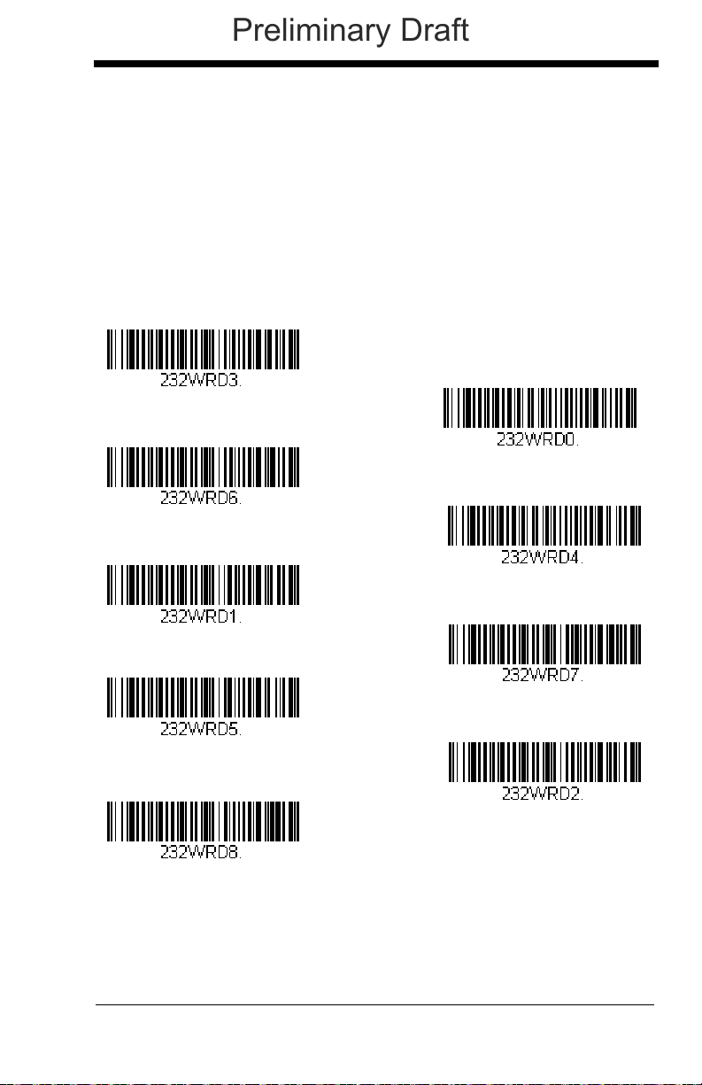
RS232 Word Length: Data Bits, Stop Bits,
7 Data, 1 Stop, Parity Even
7 Data, 1 Stop, Parity None
7 Data, 1 Stop, Parity Odd
7 Data, 2 Stop, Parity Even
7 Data, 2 Stop Parity None
* 8 Data, 1 Stop, Parity None
8 Data, 1 Stop, Parity Even
7 Data, 2 Stop, Parity Odd
8 Data, 1 Stop, Parity Odd
Preliminary Draft
and Parity
Data Bits sets the word length at 7 or 8 bits of data per character. If an applica-
tion requires only ASCII Hex characters 0 through 7F decimal (text, digits, and
punctuation), select 7 data bits. For applications that require use of the full
ASCII set, select 8 data bits per character.
Stop Bits sets the stop bits at 1 or 2.
Parity provides a means of checking character bit patterns for validity.
Default = None.
Default = 8.
Default = 1.
2 - 23
Page 56

RS232 Receiver Time-Out
RS232 Receiver Time-Out
Flow Control, No Timeout
* RTS/CTS Off
Two-Direction Flow Control
Flow Control with Timeout
Preliminary Draft
The unit stays awake to receive data until the RS232 Receiver Time-Out
expires. A manual or serial trigger resets the time-out. When an RS232
receiver is sleeping, a character may be sent to wake up the receiver and reset
the time-out. A transaction on the CTS line will also wake up the receiver. The
receiver takes 300 milliseconds to completely come up. Change the RS232
receiver time-out by scanning the bar code below, then scanning digits from the
inside back cover of this manual, then scanning Save. The range is 0 to 300
seconds.
Default = 0 seconds (no time-out - always on).
RS232 Handshaking
RS232 Handshaking allows control of data transmission from the scanner using
software commands from the host device. When RTS/CTS is turned Off, no
data flow control is used.
Flow Control, No Timeout: The scanner asserts RTS when it has data to
send, and will wait indefinitely for CTS to be asserted by the host.
Two-Direction Flow Control: The scanner asserts RTS when it is OK for the
host to transmit. The host asserts CTS when it is OK for the device to transmit.
Flow Control with Timeout: The scanner asserts RTS when it has data to
send and waits for a delay (see RS232 Timeout on page 2-25) for CTS to be
asserted by the host. If the delay time expires and CTS is not asserted, the
device transmit buffer is cleared and scanning may resume.
Default = RTS/CTS Off.
2 - 24
Page 57

RS232 Timeout
RS232 Timeout
* XON/XOFF Off
XON/XOFF On
Preliminary Draft
When using Flow Control with Timeout, you must program the length of the
delay you want to wait for CTS from the host. Set the length (in milliseconds) for a timeout by scanning the bar code below, then setting the timeout (from 1-5100 milliseconds) by scanning digits from the inside back
cover, then scanning Save.
XON/XOFF
Standard ASCII control characters can be used to tell the scanner to start
sending data (XON/XOFF On) or to stop sending data (XON/XOFF Off).
When the host sends the XOFF character (DC3, hex 13) to the scanner,
data transmission stops. To resume transmission, the host sends the XON
character (DC1, hex 11). Data transmission continues where it left off
when XOFF was sent.
Default = XON/XOFF Off
.
ACK/NAK
After transmitting data, the scanner waits for an ACK character (hex 06) or
a NAK character (hex 15) response from the host. If ACK is received, the
communications cycle is completed and the scanner looks for more bar
codes. If NAK is received, the last set of bar code data is retransmitted and
2 - 25
Page 58
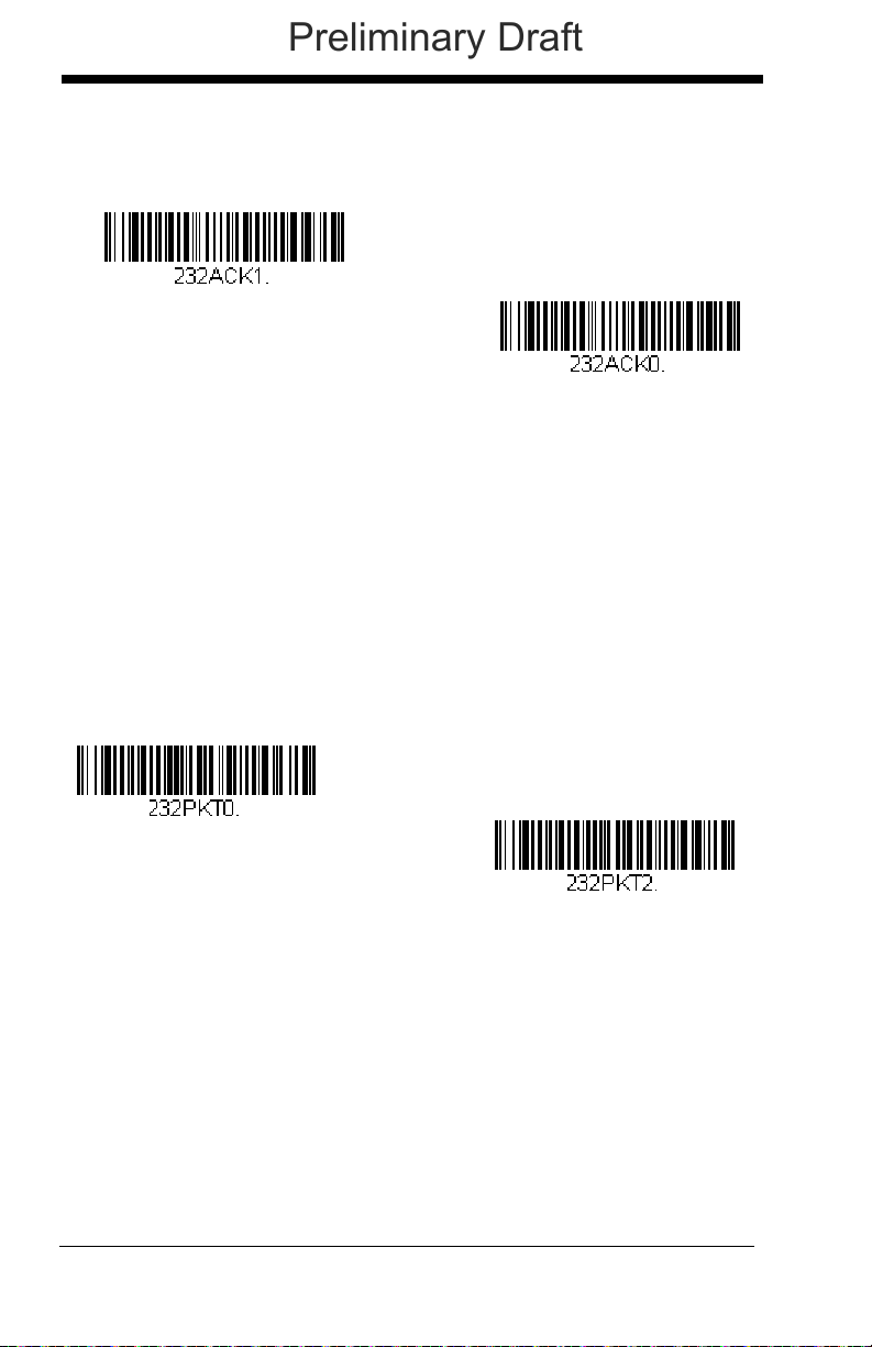
the scanner waits for ACK/NAK again. Turn on the ACK/NAK protocol by
ACK/NAK On
* ACK/NAK Off
* Packet Mode Off
Packet Mode On
Preliminary Draft
scanning the ACK/NAK On bar code below. To turn off the protocol, scan
ACK/NAK Off.
Default = ACK/NAK Off
.
Scanner to Bioptic Communication
The following settings are used to set up communication between Honeywell
scanners and bioptic scanners.
Note: The scanner’s baud rate must be set to 38400 and the RS232 timeout
must be set to 3000 in order to communicate with a bioptic scanner. See
RS232 Baud Rate on page 2-22, and RS232 Timeout on page 2-25 for
further information.
Scanner-Bioptic Packet Mode
Packet Mode On must be scanned to set the scanner’s format so it is com-
patible with a bioptic scanner.
Default = Packet Mode Off.
2 - 26
Page 59

Scanner-Bioptic ACK/NAK Mode
* Bioptic ACK/NAK Off
Bioptic ACK/NAK On
ACK/NAK Timeout
Preliminary Draft
Bioptic ACK/Nak On must be scanned so the scanner will wait for an ACK
or NAK from a bioptic scanner after each packet is sent. The ScannerBioptic ACK/NAK Timeout (below) controls how long the scanner will wait
for a response.
Default = Bioptic ACK/NAK Off.
Scanner-Bioptic ACK/NAK Timeout
This allows you to set the length (in milliseconds) for a timeout for a bioptic
scanner’s ACK/NAK response. Scan the bar code below, then set the timeout (from 1-30,000 milliseconds) by scanning digits from the inside back
cover, then scanning Save.
Default = 5100.
2 - 27
Page 60

2 - 28
Preliminary Draft
Page 61

3
Scanner
CCB01-010BT
Charge Base
Page Button and
Base LEDs
Preliminary Draft
Cordless System Operation
Note: This chapter applies only to cordless scanning systems. It does not apply
to corded scanners.
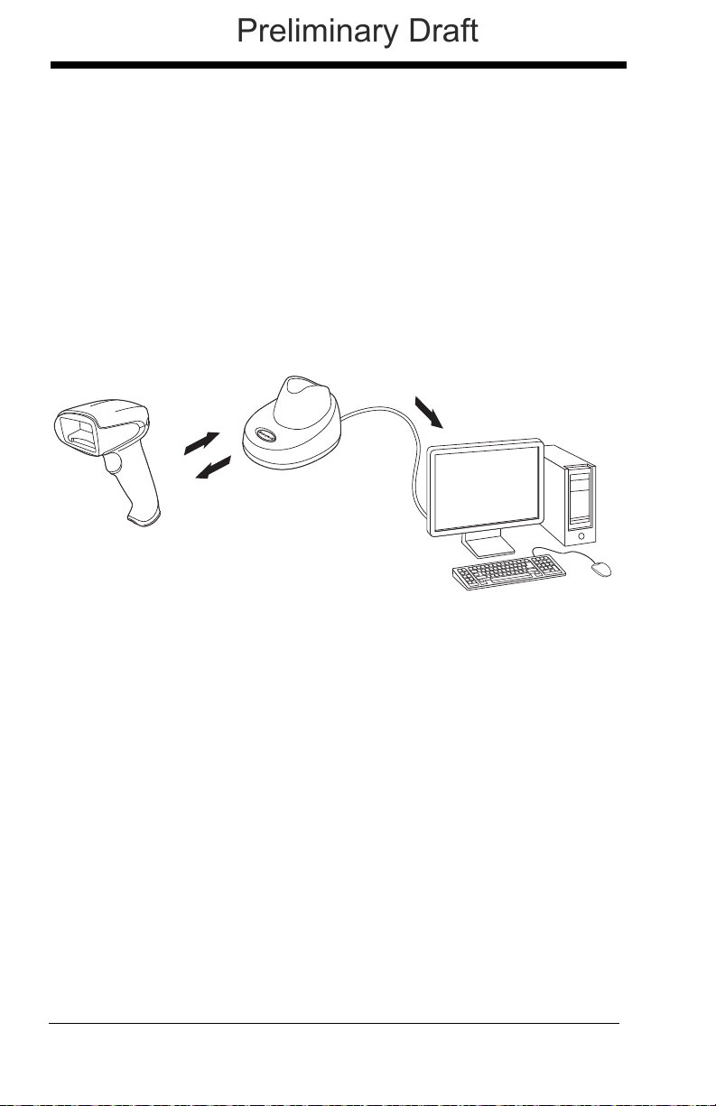
How the Cordless Base Works
The cordless base provides the link between the cordless scanner and the host
system. The base contains an interface assembly and an RF communication
module. The RF communication module performs the data exchange between
the cordless scanner and the interface assembly. The control assembly coordinates the central interface activities including: transmitting/receiving commands
and data to/from the host system, performing software activities (parameter
menuing, visual indicator support, power-on diagnostics), and data translation
required for the host system.
The base also is the scanner’s battery charger. Refer to Beeper and LED
Sequences and Meaning, page 3-5, for additional information.
Linking the Scanner to the Base
Turn off power before connecting the base, then power up the computer once
the base is fully connected. When the base is connected and powered up, put
the scanner in the base to establish a link. The green LED on the base flashes
to indicate the scanner’s battery is charging.
If the scanner and base have previously been linked, you do not receive any
feedback. If this is the first time that the scanner and base are linked, both
devices emit a short chirp when their radios link. At this point, that one scanner
is linked to one base.
To determine if your cordless system is set up correctly, scan one of the sample
bar codes in the back of this manual. If the scanner provides a single good read
beep and the green LED lights, the scanner has successfully linked to the base.
If you receive an error tone and the red LED lights, the scanner has not linked to
the base. Refer to page 13-5 for troubleshooting information.
3 - 1
Page 62
Communication Between the Cordless System
3) Base sends data to host
1
)
Go
o
d
Re
a
d
2
)
ACK
f
r
o
m
b
a
s
e
Preliminary Draft
and the Host
The cordless scanner provides immediate feedback in the form of a “good read”
indication (a green LED on the scanner and an audible beep) after a bar code is
scanned correctly and the base has acknowledged receiving the data. This is
possible since the cordless system provides two-way communication between
the scanner and the base.
When data is scanned, the data is sent to the host system via the base unit.
The cordless scanner recognizes data acknowledgement (ACK) from the base
unit. If it cannot be determined that the data has been properly sent to the
base, the scanner issues an error indication. You must then check to see if the
scanned data was received by the host system.
RF (Radio Frequency) Module Operation
The cordless system uses a two-way Bluetooth® radio to transmit and receive
data between the scanner and the base. Designed for point-to-point and multipoint-to-single point applications, the radio operates using a license free ISM
band, which sends relatively small data packets at a fast data rate over a radio
signal with randomly changing frequencies, makes the cordless system highly
responsive to a wide variety of data collection applications and resistant to
noisy RF environments. Bluetooth Class 2 power level provides a communication range of 33 feet (10m) between the scanner and base/Bluetooth adapter,
depending on the environment.
System Conditions
The components of the cordless system interact in specific ways as you associate a scanner to a base, as you move a scanner out of range, bring a scanner
back in range, or swap scanners between two cordless systems. The following
information explains the cordless system operating conditions.
3 - 2
Page 63

Linking Process
!
Preliminary Draft
Once a scanner is placed into the base, the scanner’s battery charge status
is checked, and software automatically detects the scanner and links it to
the base depending on the selected link mode.
Scanner Is Out of Range
The cordless scanner is in communication with its base, even when it is not
transmitting bar code data. Whenever the scanner can’t communicate with
the base for a few seconds, it is out of range. If the scanner is out of range
and you scan a bar code, the scanner issues an error tone indicating no
communication with the base. In addition, your scanner and base can
sound an alarm if programmed to emit an alarm. Refer to Out-of-Range
Alarm, page 3-12.
Scanner Is Moved Back Into Range
The scanner re-links if the scanner or the base have been reset or the
scanner comes back into range. If the scanner re-links, you will hear a single chirp when the re-linking process (uploading of the parameter table) is
complete.
OutofRangeandBackintoRange with Batch Mode On
The scanner may store a number of symbols (approximately 500 U.P.C.
symbols; others may vary) when out of range and then send them to the
base when back in range (see Batch Mode on page 3-14).
You will not hear a communication error tone in this mode, but you will hear
a short buzz when you pull the trigger if the radio communication is not
working. Once the radio connection is made, the scanner produces a
series of beeps while the data is being transferred to the base.
Page Button
When you press the Page button on the base, the scanners associated with
that base will begin beeping (3 short and 1 long beep). If you pull the trigger on a scanner that is beeping in response, that scanner will stop beeping. If you press the Page button on the base a second time, all associated
scanners will stop beeping. See Paging on page 3-8 for further information
about Page Button settings.
About the Battery
There is a danger of explosion if the batteries are incorrectly replaced.
Replace the batteries with only the same or equivalent type recommended by the manufacturer. Dispose of used batteries according to
the recycle program for batteries as directed by the governing agency
for the country where the batteries are to be discarded.
3 - 3
Page 64

Power is supplied to the cordless scanner by a rechargeable battery that is inte-
Preliminary Draft
grated in the scanner handle. Batteries are shipped approximately 30% to 60%
charged and should be fully charged for maximum charge capacity.
Charging Information
The battery is designed to charge while the scanner is positioned in the
cordless base unit. Refer to Base LED Sequences and Meaning, page 36, for an interpretation of the Charge Status indicators.
Place the scanner in the base that is connected to an appropriate power
supply.
Note: If you are powering the base through the interface cable (for
example, a USB cable) and not using an external power supply
plugged into the aux port, the current available for charging is
reduced and charge times are increased.
Battery Recommendations
• The battery is a lithium ion cell and can be used without a full charge, and
can also be charged without fully discharging, without impacting the
battery life. There is no need to perform any charge/discharge
conditioning on this type of battery.
• Keep the base connected to power when the host is not in use.
• Replace a defective battery immediately since it could damage the
scanner.
• Although your battery can be recharged many times, it will eventually be
depleted. Replace it after the battery is unable to hold an adequate
charge.
• If you are not sure if the battery or charger is working properly, send it to
Honeywell International Inc. or an authorized service center for
inspection. Refer to Customer Support on page 14-1 for additional
information.
Safety Precautions for Lithium Batteries
• Do not place batteries in fire or heat the batteries.
• Do not store batteries near fire or other high temperature locations.
• Do not store or carry batteries together with metal objects.
• Do not expose batteries to water or allow the batteries to get wet.
• Do not connect (short) the positive and negative terminals, of the
batteries, to each other with any metal object.
• Do not pierce, strike, or step on batteries or subject batteries to strong
impacts or shocks.
• Do not disassemble or modify batteries.
3 - 4
Page 65

Proper Disposal of the Battery
Preliminary Draft
When the battery has reached the end of its useful life,
the battery should be disposed of by a qualified recycler
or hazardous materials handler. Do not incinerate the
battery or dispose of the battery with general waste
materials. You may send the scanner’s battery to us.
(postage paid). The shipper is responsible for complying
with all federal, state, and local laws and regulations
ping of spent batteries. Contact the Product Service Department (page 14-
1) for recycling or disposal information. Since you may find that your cost
of returning the batteries significant, it may be more cost effective to locate
a local recycle/disposal company.
related to the packing, labeling, manifesting, and ship-
Beeper and LED Sequences and Meaning
The scanner contains LEDs on the top of the unit to indicate its power up, communication, and battery status. Simply stated, red LED = error; green
LED = success of any type. The unit’s audible indicators have meaning as well:
1 razz or error tone = error; 2 beeps = menu change; 1 beep = all other successes.
The table below lists the indication and cause of the LED illumination and beeps
for the scanner.
3 - 5
Page 66

Scanner LED Sequences and Meaning
Preliminary Draft
LED Indication Beeper Indication Cause
Normal Operation
Red Flash None Battery low
Green Flash 1 beep Successful
communication or linking
Red, blinking Razz or error tone Failed communication
Menu Operation
Green Flash 2 beeps Successful menu change
Red, blinking Razz or error tone Unsuccessful menu
change
Base LED Sequences and Meaning
The base contains a red LED that indicates the status of the unit and verifies its communication with the host system and a green LED that indicates
scanner battery charge condition.
Charge Condition Charge Status Indicator (Green LED)
Scanner inserted into base Three flashes
>80% charged On continuously
30% to 80% charged Slow flash, 1 second on, 1 second off
<30% charged Fast flash, 300 mSec on, 300 mSec off
Note: Charging only occurs with external power applied to the charge base
or 12 volt host power.
The table below lists the indication and cause of the LED illumination and
beeps for the CCB01-010BT charge base.
System Condition System Status Indicator (Red LED)
Power On/System Idle LED is on
Receiving Data (charge
base only)
Base requests status from
its own Bluetooth radio
3 - 6
Blink LED for short duration in multiple
pulses. Occurs while transferring data to/
from the RF module or the Host port.
Blink LED once (occurs approx. every 30
seconds)
Page 67
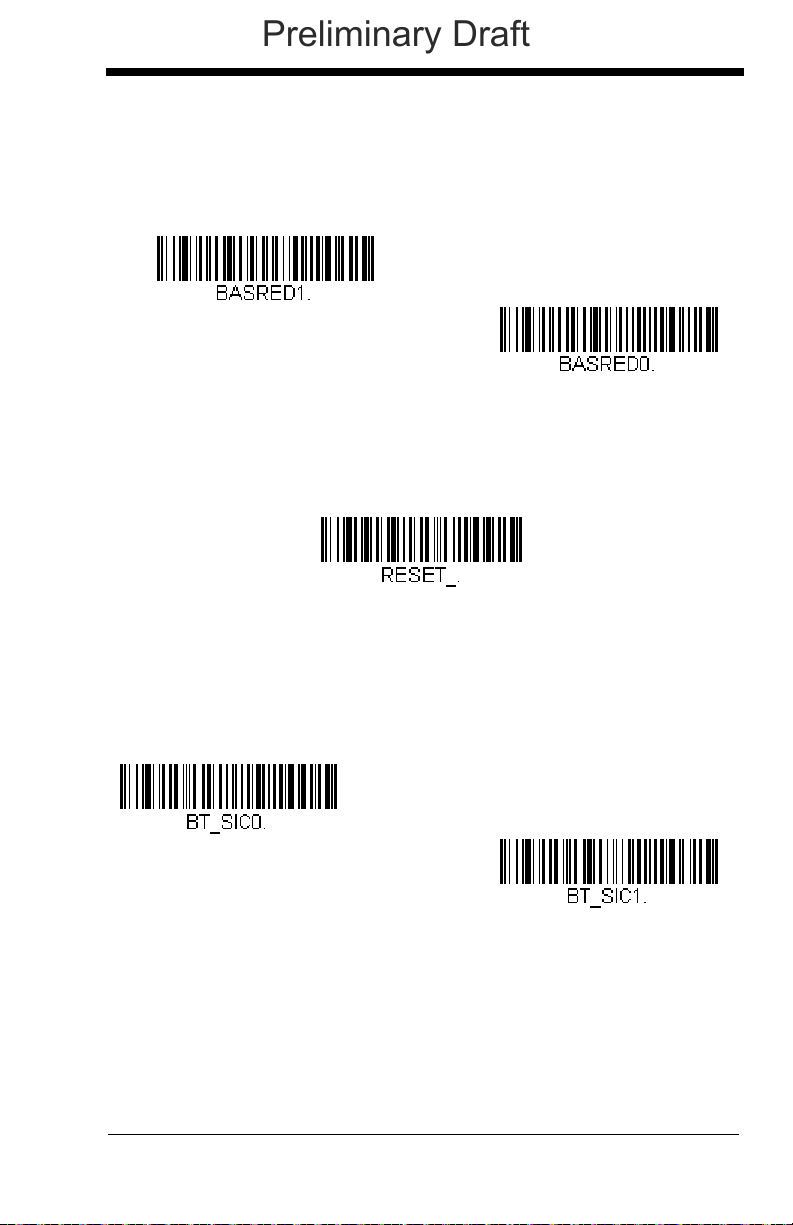
Base Power Communication Indicator
* Base Power Communication
Indicator On
Base Power Communication
Indicator Off
Reset Scanner
* Scanning in Cradle Off
Scanning in Cradle On
Preliminary Draft
To display the power indicator on the base, scan the Base Power Communication Indicator On bar code. To turn off the power indicator, scan the Off
bar code.
Default = On
.
Reset Scanner
Scanning this bar code causes the scanner to re-link with the base.
Scanning while in Base Cradle
If you want to be able to scan bar codes while the scanner is in the base cradle,
scan the Scanning in Cradle on bar code below. If you want to only allow scanning when the scanner is out of the base cradle, scan Scanning in Cradle Off.
Default = Scanning in Cradle Off
.
3 - 7
Page 68

Paging
* Paging Mode On
Paging Mode Off
* Low (1000 Hz)
Medium (3250 Hz)
High (4200 Hz)
Preliminary Draft
Paging Mode
By default, the paging button on the base pages the scanners associated
with that base. If you want the paging button on your base to be disabled,
scan the Paging Mode Off bar code, below. When Paging Mode is off, the
base will no longer page scanners when the button is pressed. The red
LED on the base will remain lit to indicate that Paging Mode is off. (This
light will go out when the button is pressed, then back on when it’s
released.)
Default = Paging Mode On.
Paging
When you press the Page button on the base, the scanners associated
with that base will begin beeping (see Page Button on page 3-3). You can
set the pitch of the paging beep for each scanner by scanning one of the
following bar codes.
Pitch
Default = Low.
3 - 8
Page 69

Error Indicators
* Razz (250 Hz)
Medium (3250 Hz)
High (4200 Hz)
Number of Base Error Beeps/LED Flashes
Scanner Report
Preliminary Draft
Beeper Pitch - Base Error
The base can be configured to beep at a particular pitch when an error
occurs, such as transmission problems to a host system. The beeper pitch
codes modify the pitch (frequency) of the error tone the base emits when
there is an error.
Number of Beeps - Base Error
The number of beeps and LED flashes emitted by the base for an error
condition can be programmed from 1 - 9. For example, if you program this
option to have five error beeps, there will be five error beeps and five LED
flashes in response to an error. To change the number of error beeps, scan
the bar code below and then scan a digit (1-9) bar code and the Save bar
code on the Programming Chart inside the back cover of this manual.
Default = 1.
Default = Low.
Scanner Report
Scan the bar code below to generate a report for the connected scanners. The
report indicates the port, work group, scanner name, and address. To assign a
name to your scanner, refer to Menu Command Syntax, page 11-1.
3 - 9
Page 70

Scanner Address
Scanner Address
Base Address
Charge Only Mode
* Charge and Link Mode
Preliminary Draft
Scan the bar code below to determine the address of the scanner you are
using.
Base Address
Scan the bar code below to determine the address of the base you are using.
Single Scanner Modes
The Xenon is capable of working in single scanner mode, multiple scanner
mode, or with Bluetooth devices other than the CCB01-010BT charge base.
Charge Only Mode
There may be times when you want to charge your scanner, but not link to
the base. For example, if the scanner is linked to a Bluetooth device and
you need to charge the scanner, but want to retain your existing link. To do
so, scan the Charge Only Mode bar code. If you want to charge the scanner and link to the base, scan Charge and Link Mode.
and Link Mode.
Default = Charge
Note: When in Charge Only Mode, the scanner periodically wakes up
and beeps. See "Power Up Beeper" on page 4-1 to change this
setting.
Note: If you have scanned Charge Only Mode, and then scan the
linking bar code on the base, the scanner will link to the base.
3 - 10
Page 71

Linked Modes
Locked Link Mode
(Single Scanner)
* Open Link Mode
(Single Scanner)
Unlink Scanner
Preliminary Draft
Locked Link Mode and Open Link Mode are the link modes that accommodate different applications. Scan the appropriate bar codes included in the
Open Link and Locked Link Mode explanations that follow to switch from
one mode to another.
Locked Link Mode - Single Scanner
If you link a scanner to a base using the Locked Link Mode, other
scanners are blocked from being linked if they are inadvertently placed
into the base. If you do place a different scanner into the base, it will
charge the scanner, but the scanner will not be linked.
To use a different scanner, you need to unlink the original scanner by
scanning the Unlink Scanner bar code. (See Single Scanner
Modes, page 3-10.)
Open Link Mode - Single Scanner
When newly shipped or defaulted to factory settings, the base and
scanner are not linked. By placing a scanner into the base, they establish a link. Placing a different scanner into the base establishes a new
link and the old scanner is unlinked. Each time a scanner is placed
into the base, it becomes the linked scanner; the old scanner is
unlinked.
Default = Open Link Mode
.
Unlinking the Scanner
If the base has a scanner linked to it, that scanner must be unlinked before a
new scanner can be linked. Once the previous scanner is unlinked, it will no
longer communicate with the base. To unlink a scanner from the base, scan the
Unlink Scanner bar code below.
3 - 11
Page 72

Override Locked Scanner
Override Locked Scanner
(Single Scanner)
Base Alarm Duration
Scanner Alarm Duration
Preliminary Draft
If you need to replace a broken or lost scanner that is linked to a base,
scan the Override Locked Scanner bar code below with a new scanner
and place that scanner in the base. The locked link will be overridden; the
broken or lost scanner’s link with the base will be removed, and the new
scanner will be linked.
Out-of-Range Alarm
If your scanner is out range of the base, an alarm sounds from both your base
and scanner. The alarm stops when the scanner is moved closer to the base,
when the base connects to another scanner, or when the alarm duration
expires. To activate the alarm options for the scanner or the base and to set the
alarm duration, scan the appropriate bar code below and then set the time-out
duration (from 0-3000 seconds) by scanning digits on the Programming Chart
inside the back cover, then scanning Save.
Default = 0 sec (no alarm).
Note: If you are out of range when you scan a bar code, you will receive an error
tone even if you do not have the alarm set. You receive the error tone
since the data could not be communicated to the base or the host.
Alarm Sound Type
If you have set the out-of-range alarm enabled, you may change the alarm
type for the scanner or base by scanning the appropriate bar code below
and then scanning a digit (0-7) bar code and the Save bar code on the
Programming Chart inside the back cover of this manual.
The sounds are as follows:
Setting Sound
0 3 long beeps, medium pitch
1 3 long beeps, high pitch
3 - 12
Default = 0.
Page 73

Setting Sound
Base Alarm Type
Scanner Alarm Type
F
u
l
l
P
o
w
e
r
R
e
d
u
c
e
d
P
o
w
e
r
1902
Scanner
802.11
LAN
Preliminary Draft
2 4 short beeps, medium pitch
3 4 short beeps, high pitch
4 single chirps, medium pitch
5 2 chirps, then 1 chirp, medium pitch
6 single chirps, high pitch
7 2 chirps, then 1 chirp, high pitch
Flexible Power Management
If you are experiencing network performance issues, and suspect the scanner is
interfering with other devices, you can turn down the power output of the scanner. This reduces the range between the scanner and the base as shown in the
following illustration:
Scan one of the bar codes below to set the scanner’s power output to Full
Power (100%) [2.5mW, 4dBm], Medium Power (35%) [.875mW, 0dBm],
Medium Low Power (5%) [.125mW, -9dBm], or Low Power (1%, .025mW,
-16dBm).
Default = Full Power.
3 - 13
Page 74
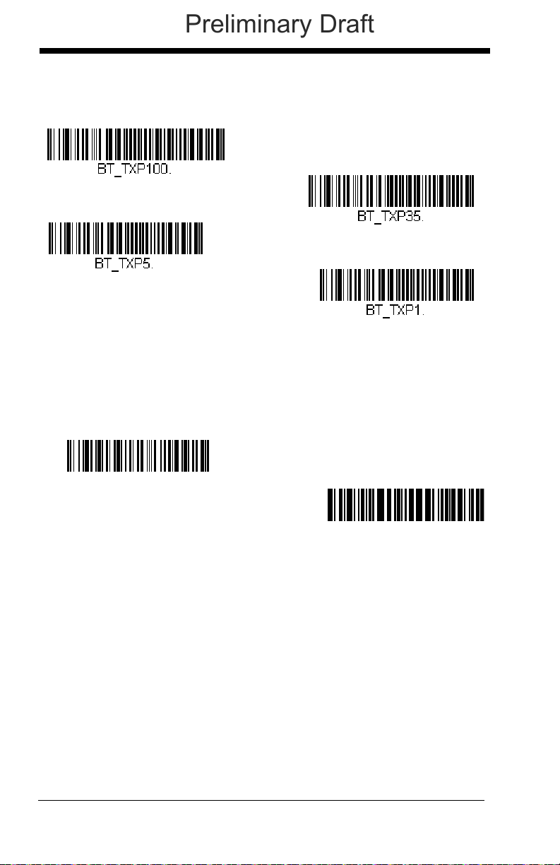
For the new power setting to take effect, the scanner and base must be reset.
* Full Power
Medium Power
Medium Low Power
Low Power
:*:RESET_.³
Reset Base
Reset Scanner
Preliminary Draft
See Reset Scanner and Base (page 3-14).
Reset Scanner and Base
Once the power level is set, you must scan the Reset Base bar code and
wait for the scanner to unlink and relink to the base. Once that is done,
scan the Reset Scanner bar code and wait for the base to unlink and relink
to the scanner.
Batch Mode
Batch mode is used to store bar code data when a scanner is out of range of its
base, or when performing inventory. The data is transmitted to the base once
the scanner is back in range or when the records are manually transmitted.
Note: Batch mode has limitations when using multiple scanners to one base. If
a cordless system is being used in "multiple link mode," where up to 7
scanners are to be connected to one base, some accumulated or batched
scans could be lost if scanners are constantly being moved in and out of
range.
Automatic Batch Mode stores bar code data when the scanner is out of range
of the base. The data is automatically transmitted to the base once the scanner
is back in range. When the scanner’s buffer space is full, any bar codes
scanned generate an error tone. In order to scan bar codes again, the scanner
must be moved back into range of the base so data can be transmitted.
3 - 14
Page 75
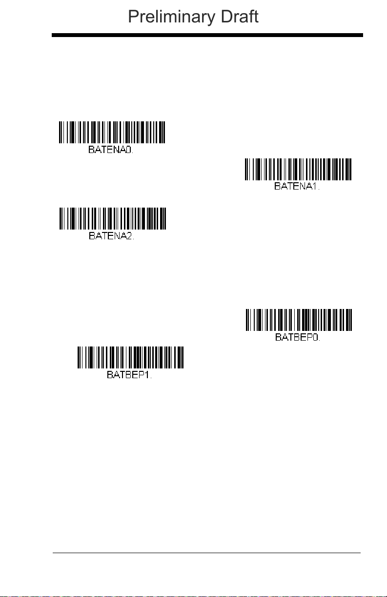
Inventory Batch Mode stores bar code data, whether or not you are in range of
Automatic Batch Mode
* Batch Mode Off
Inventory Batch Mode
* Batch Mode Beep On
Batch Mode Beep Off
Preliminary Draft
the base. To transmit the stored data to the base, either place the scanner in
the base, or scan Transmit Inventory Records (page 3-19). When the scanner’s
buffer space is full, any bar codes scanned generate an error tone. In order to
scan bar codes again, the data must be transmitted to the base.
Default = Batch Mode Off.
Batch Mode Beep
Scan Batch Mode Beep On to program the scanner to beep when it enters
Batch Mode.
Default = Batch Mode Beep On.
Batch Mode Storage
When a scanner is storing data during a Batch Mode process, you can
select whether the data is stored in Flash memory or in RAM.
Flash Storage: The scanner writes any untransmitted data to flash memory prior to powering down. The data will still be there when the scanner
powers back up. However, the scanner will power down, even with untransmitted data, if it reaches a power down timeout or if the battery power is
very low.
3 - 15
Page 76

RAM Storage: The scanner will not power down while it contains data that
RAM Storage
* Flash Storage
Batch Mode Quantity On
* Batch Mode Quantity Off
Preliminary Draft
has not been transmitted to the base, even if it reaches a power down timeout. However, if the scanner runs out of battery power, it will power down
and the data will be lost.
Default = Flash Storage.
Batch Mode Quantity
When in Batch Mode, you may wish to transmit the number of multiple bar
codes scanned, rather than a single bar code multiple times. For example,
if you scan three bar codes called XYZ with Batch Mode Quantity Off,
when you transmit your data it will appear as XYZ three times. Using
Batch Mode Quantity On and the Quantity Codes (page 3-17), you could
ouptut your data as “XYZ, 00003” instead.
Off.
Default = Batch Mode Quantity
Entering Quantities
Quantity Codes (page 3-17) allow you to enter a quantity for the last item
scanned, up to 9999 (default = 1). Quantity digits are shifted from right to
left, so if a 5th digit is scanned, the 1st digit scanned is discarded and the
2nd, 3rd and 4th digits are moved to the left to accommodate the new digit.
For example, if the Quantity 5 bar code is scanned after the quantity has
been set to 1234, then the 1 is dropped, the quantity will be 2345.
Example: Add a quantity of 5 for the last item scanned.
1. Scan the item's bar code.
2. Scan the quantity 5 bar code.
Example: Add a quantity of 1,500 for the last item scanned.
1. Scan the item's bar code.
3 - 16
Page 77
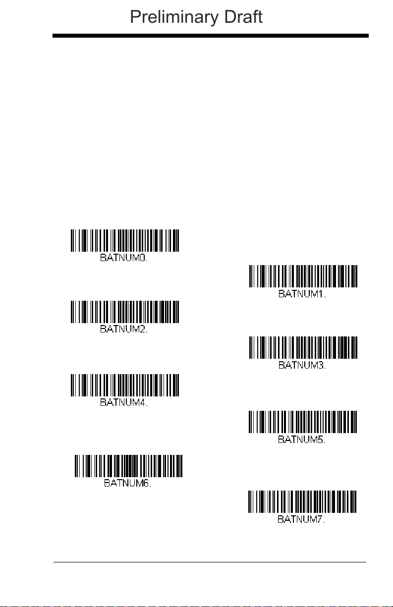
2. Scan the quantity 1 bar code.
1
0
3
2
4
6
5
7
Preliminary Draft
3. Scan the quantity 5 bar code.
4. Scan the quantity 0 bar code.
5. Scan the quantity 0 bar code.
Example: Change a quantity of 103 to 10.
To correct an incorrect quantity, scan the quantity 0 bar code to replace the
incorrect digits, then scan the correct quantity bar codes.
1. Scan the quantity 0 bar code to change the quantity to 1030.
2. Scan the quantity 0 bar code to change the quantity to 0300.
3. Scan the quantity 1 bar code to change the quantity to 3001.
4. Scan the quantity 0 bar code to change the quantity to 0010.
Default = 1.
Quantity Codes
3 - 17
Page 78
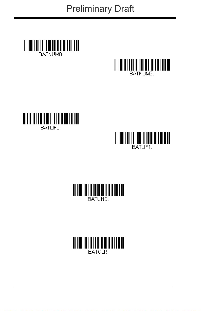
Quantity Codes (continued)
8
9
Batch Mode LIFO
Batch Mode FIFO
Delete Last Code
Clear All Codes
Preliminary Draft
Batch Mode Output Order
When data is transmitted to the base, select whether you want that data
sent as FIFO (first-in first-out), or LIFO (last-in last-out).
Delete Last Code
If you are accumulating data in Batch Mode and want to delete the last bar
code scanned, scan Delete Last Code.
Clear All Codes
If you want to clear the scanner’s buffer of all data accumulated in Batch
Mode, scan Clear All Codes.
3 - 18
Page 79
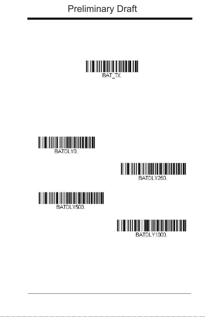
Transmit Records to Host
Transmit Inventory Records
* Batch Mode Transmit Delay Off
(No Delay)
Batch Mode Transmit Delay Short
(250 ms)
Batch Mode Transmit Delay Medium
(500 ms)
Batch Mode Transmit Delay Long
(1000 ms)
Preliminary Draft
If you are operating in Inventory Batch Mode (see Inventory Batch Mode on
page 3-15), you must scan the following bar code to transmit all the stored
data to the host system.
Batch Mode Transmit Delay
Sometimes when accumulated scans are sent to the host system, the
transmission of those scans is too fast for the application to process. To
program a transmit delay between accumulated scans, scan one of the following delays.
Note: In most cases, a short (250 ms (milliseconds) delay is ideal; however,
longer delays may be programmed. Contact Technical Support
(page 14-3) for additional information.
Default = Off.
Multiple Scanner Operation
Note: Multiple Scanner Operation Mode allows you to link up to 7 scanners to
one base. You cannot join an 8th scanner until you unlink one of the 7
scanners or take a scanner out of range.
3 - 19
Page 80

To put the scanner in multiple scanner mode, scan the bar code below. Once
Multiple Scanner Operation
Preliminary Draft
you scan this bar code, the scanner is unlinked from the base and must be
placed into the base to re-link.
Scanner Name
You may assign a name to each scanner you are using. When you have multiple scanners linked to one base, you may want to name each scanner so you
will be able to control the scanner receiving imaging commands sent from the
base.
The default name for a Xenon is “Xenon.” If you have more than one scanner
linked to a base, and they all have the default names, the first scanner linked to
the base receives commands. You can change the name of a scanner using a
serial command (refer to Scanner Name, page 11-15) or using a bar code command. To change the name serially, unlink all except one of the scanners from
the base. Send “:Xenon:BT_NAM
name. If you wish to change the names of additional scanners, re-link them one
at a time and repeat the “:Xenon:BT_NAM
name
.”, where
name.”
name
is the new scanner
command for each scanner.
3 - 20
Page 81

To rename scanners with sequential, numeric names, scan the bar codes
0001
0002
0003
0005
0007
0004
Reset
0006
Scanner Name
Preliminary Draft
below.
to re-link to the base before scanning another bar code to rename the next
scanner.
Scan the Reset code after each name change and wait for the scanner
Alternatively, you may change the name with a bar code command if you cannot
send serial commands to the base. One way to do this is to scan the bar code
below and scan a number for the scanner name. For example, if you had 7
scanners to one base, scan the bar code below with the first scanner, scan the
1 bar code on the Programming Chart inside the back cover of this manual and
scan Save. Then scan the Reset bar code and wait for the scanner to re-link to
the base before scanning the next bar code. Repeat that process for scanner
number 2, 3, 4, etc.
3 - 21
Page 82

If you want to assign an alphabetic name to the scanner, create a Code 128 bar
Preliminary Draft
code containing “~BT_NAM
83), where
21 or on the Programming Chart inside the back cover of this manual).
name
is the new scanner name. Scan the Reset bar code (page 3-
name
.” followed by a FNC3 character (hexidecimal
Application Work Groups
Your cordless system can have up to 7 scanners linked to one base. You can
also have up to 7 work groups. If you want to have all of the scanners’ settings
programmed alike, you don’t need to use more than 1 work group. If you want
each scanner to have unique settings (e.g., beeper volume, prefix/suffix, data
formatter), then you may program each scanner to its own unique work group
and may program each scanner independently. For example, you might want to
have multiple work groups in a retail/warehouse application where you need to
have different data appended to bar codes used in the warehouse area versus
the retail area. You could assign all the scanners in the retail area to one work
group and those in the warehouse to another. Consequently, any desired
changes to either the retail or warehouse area would apply to all scanners in
that particular work group. EZConfig (page 10-2) makes it easy for you to program your system for use with multiple scanners and multiple work groups.
The scanner keeps a copy of the menu settings it is using. Whenever the scanner is connected or reconnected to a base, the scanner is updated with the latest settings from the base for its work group. The scanner also receives menu
setting changes processed by the base. If a scanner is removed from one base
and placed into another base, it will be updated with the new base settings for
whatever work group that the scanner was previously assigned. For example, if
the scanner was in work group 1 linked to the first base, it will be placed in work
group 1 in the second base with the associated settings.
3 - 22
Page 83
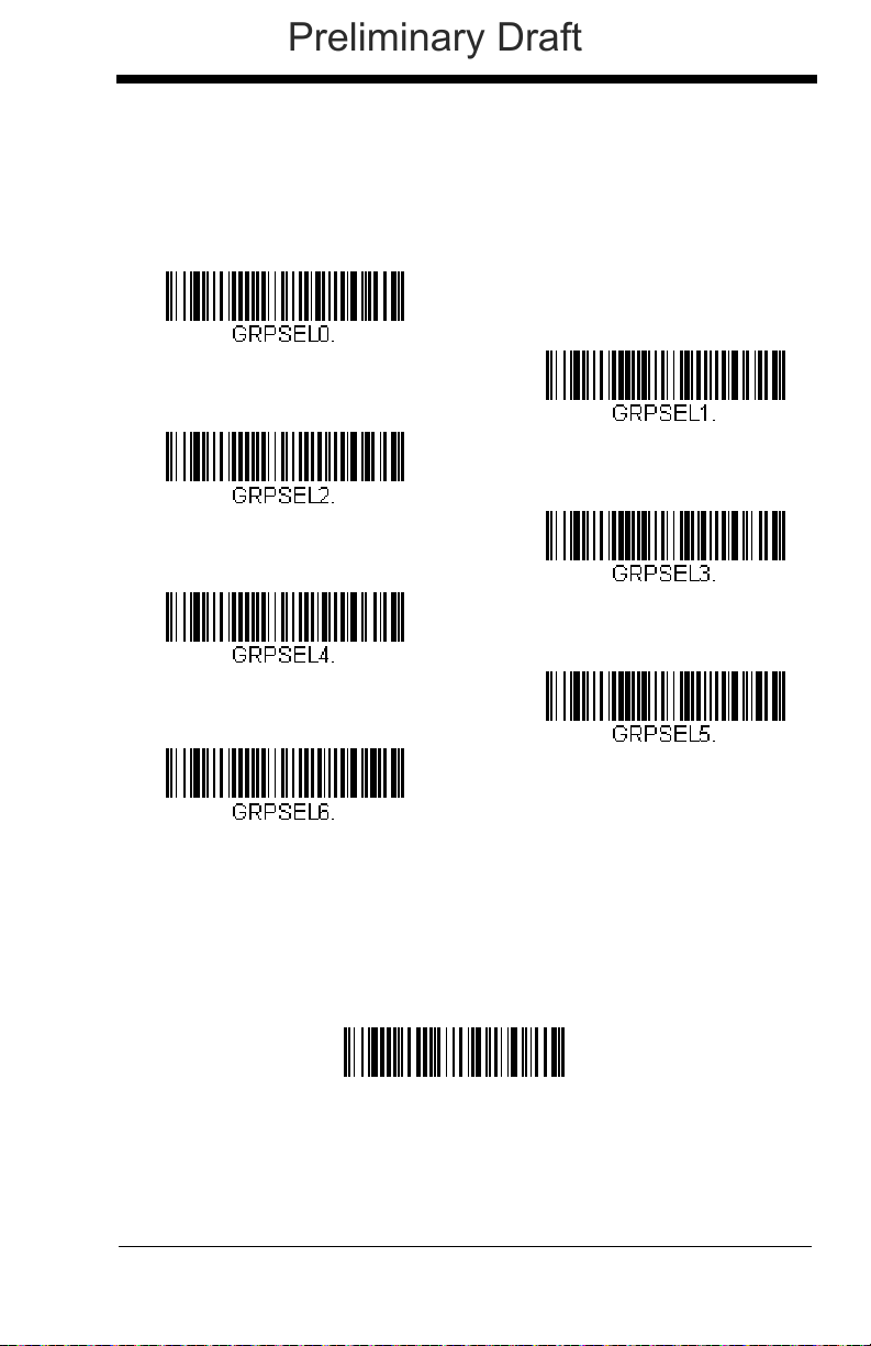
Application Work Group Selection
* Group 0
Group 1
Group 2
Group 4
Group 6
Group 5
Group 3
Factory Default Settings:
All Work Groups
PAPDFT&
Preliminary Draft
This programming selection allows you to assign a scanner to a work group
by scanning the bar code below. You may then program the settings (e.g.,
beeper volume, prefix/suffix, data formatter) that your application requires.
Default = Group 0.
Resetting the Factory Defaults: All Application Work Groups
The following bar code defaults all of the work groups to the factory default settings.
3 - 23
Page 84

To see what the factory default settings are, refer to the table of Menu
Custom Default Settings:
All Work Groups
Preliminary Draft
Commands, beginning on page 11-5. The standard product default settings for
each of the commands are indicated by an asterisk (*).
Note: Scanning this bar code also causes both the scanner and the base to
perform a reset and become unlinked. The scanner must be placed in its
base to re-establish the link. Refer to Single Scanner Modes, page 3-10
for additional information.
If your scanner is in multiple scanner mode, you will hear up to 30
seconds of beeping while all scanners are re-linked to the base and the
settings are changed.
Resetting the Custom Defaults: All Application Work Groups
If you want the custom default settings restored to all of the work groups, scan
the Custom Product Default Settings bar code below. (If there are no custom
defaults, it will reset the work groups to the factory defaults.) See Setting
Custom Defaults on page 1-9 for further information about custom defaults.
Note: Scanning this bar code also causes both the scanner and the base to
perform a reset and become unlinked. The scanner must be placed in its
base to re-establish the link. Refer to Single Scanner Modes, page 3-10
for additional information.
If your scanner is in multiple scanner mode, you will hear up to 30
seconds of beeping while all scanners are re-linked to the base and the
settings are changed.
Using the Scanner with Bluetooth Devices
The scanner can be used either with the CCB01-010BT charge base or with
other Bluetooth devices. Those devices include personal computers, laptops,
PDAs, and Honeywell mobility systems devices.
PCs/Laptops
Scanning the Non-Base BT Connection bar code below allows the scanner to be used with other Bluetooth devices (e.g., PC/laptop). After you
scan the bar code below, follow the instructions supplied with your Bluetooth device to locate the scanner and connect to it. If you go out of range
3 - 24
Page 85

with your scanner, the scanner will not reconnect to the Bluetooth device
Non-Base BT Connection
BT Connection - PDA/Mobility Systems Device
Bluetooth PIN
Preliminary Draft
when it is back in range. If you want to re-link to the charge base, refer to
Override Locked Scanner, page 3-12.
Note: The multiple work groups option is not available when you are using
the scanner with Bluetooth devices other than the charge base.
PDAs/Mobility Systems Devices
You may also use the scanner with a PDA or a Honeywell Mobility Systems
device. Scan the bar code below and follow the instructions supplied with
your Bluetooth device to locate the scanner, and connect with it.
Changing the Scanner’s Bluetooth PIN Code
Some devices require a PIN code as part of the Bluetooth security features.
Your scanner’s default PIN is 1234, which you may need to enter the first
time you connect to your PDA or PC. The PIN code must be between 1
and 16 characters. To change the PIN, scan the bar code below and then
scan the appropriate numeric bar codes from the Programming Chart
inside the back cover of this manual. Scan Save to save your selection.
Minimizing Bluetooth/ISM Band Network Activity
The settings described below can help you customize the re-linking behavior of
the cordless area-imaging system to obtain the best compromise between convenience and low interference.
Note: ISM band refers to the 2.4 to 2.48 GHz frequency band used by wireless
networks, cordless phones, and Bluetooth.
3 - 25
Page 86

Auto Reconnect Mode
* Auto Reconnect On
Auto Reconnect Off
Preliminary Draft
Auto Reconnect controls whether or not the scanner automatically begins
the re-link process when a loss of connection is detected. When the Auto
Reconnect On bar code is scanned, the scanner begins the re-link process immediately, without user intervention.
Note: If you are connecting to a Bluetooth Interface Module, set Auto
Reconnect to Off.
The table below shows the results of the Auto Reconnect On and Off settings:
Event Auto Reconnect On Auto Reconnect Off
Default = Auto Reconnect On.
Scanner out of
range
Base reset
(firmware upgrade
or power cycle)
Scanner power
down due to Power
Time-Out Timer
setting (see page 4-
7)
3 - 26
Re-link occurs
automatically. If
maximum number of link
attempts (see Maximum
Link Attempts on page
3-27) is unsuccessful,
then the trigger must be
pulled or the scanner
must be placed in the
base unit to re-link.
Scanner behaves as if
out of range.
Trigger must be pulled or the scanner must be
placed in the base unit to re-link.
(Note: scanner re-links on power up, but powers
on due to one of the above actions.)
The trigger must be
pulled to initiate relinking.
No attempt to re-link
made while base unit
is powered off.
Tri gg e r m u st b e
pulled to initiate relinking.
Page 87

Event Auto Reconnect On Auto Reconnect Off
Maximum Link Attempts
Preliminary Draft
Scanner reset due
to firmware
upgrade
Scanner reset due
to battery change
Scanner placed in
different base unit
Re-link occurs automatically.
Re-link occurs automatically.
Re-link to new base occurs automatically.
Maximum Link Attempts
The Maximum Link Attempts setting controls the number of times the scanner tries to form a connection with a base unit or PC. During the connection setup process, the scanner transmits in order to search for and
connect to a base unit. In order to prevent continuous transmissions that
could interfere with other users of the ISM band, the number of attempts to
connect is limited by this setting. After the maximum number of attempts is
reached, the scanner will not attempt to reconnect to the base unit. Pressing the trigger or placing the scanner in the cradle resets the attempt count
and the scanner will again try to link to the base unit. When set to zero, the
scanner will try to link until the Power Time-Out Timer setting (see page 4-
7) expires.
Scan the Maximum Link Attempts bar code, then scan the number of
attempts for the setting (from 0-100) from the inside back cover. Scan Save
to save the setting.
Default = 0.
Relink Time-Out
Relink Time-Out controls the idle time between re-link attempts. An
attempt to link a scanner to a base unit typically lasts up to 5 seconds. This
is the time when the scanner is actually attempting to contact base unit.
Relink Time-Out controls the amount of time, in seconds, that elapses
between the end of one connection attempt and the start of the next.
Note: The length of time for an attempt depends on the number of scanners
connected to a base unit. An extra 7 seconds may be required when
a connection is successful.
3 - 27
Page 88

Scan the Relink Time-Out bar code, then scan the number of seconds for
Relink Time-Out
Preliminary Draft
the setting (from 1-100) from the inside back cover. Scan Save to save the
setting.
Default = 3 seconds.
Bluetooth/ISM Network Activity Examples
Default values
When the scanner goes out of range, the scanner repeatedly attempts to
connect to base unit. Each attempt consists of approximately 5 seconds of
active time followed by 3 seconds of idle time. After one hour, the scanner
powers off and batch mode data is lost.
Maximum Link Attempts set to 15
Other values at default setting
When the scanner goes out of range, 15 attempts are made to link to the
base unit. Each attempt consists of approximately 5 seconds of active time
followed by 3 seconds of idle time. After 15 cycles (8*15 =120), or about 2
minutes, the scanner stops trying to connect to the base unit, but retains
any bar codes that may have been saved in batch mode. After one hour,
the scanner powers off and batch mode data is lost.
Auto Reconnect Mode set to 0
Maximum Link Attempts set to 15
Other values at default setting
When the scanner goes out of range, no action is taken to re-link. When
the trigger is pulled, 15 attempts are made to link to the base unit. Each
attempt consists of approximately 5 seconds of active time followed by 3
seconds of idle time. After 15 cycles (8*15 =120), or about 2 minutes, the
scanner stops trying to connect to the base unit, but retains any bar codes
that may have been saved in batch mode. After one hour, the scanner
powers off and batch mode data is lost. Refer to Auto Reconnect
Mode, page 3-26, to review other events that can start the re-link process.
Auto Reconnect Mode set to 1
Maximum Link Attempts set to 0
Relink Time-Out set to 10
Scanner Power Time-Out Timer set to 1800
Note: See Scanner Power Time-Out Timer on page 4-7.
The scanner attempts to connect to the base unit every 15 seconds, measured from start of attempt to start of attempt. After one half hour, the
scanner powers off.
3 - 28
Page 89

Host Command Acknowledgment
Preliminary Draft
Some applications require that the host terminal (or server) approve or reject
incoming bar code data and notify the operator of these actions. These applications require that the host maintain control over the response indicators emitted
from the scanner. Turning on Host ACK configures the scanner to respond to
commands from the host system.
Note: System performance degrades when using Host ACK at rates lower than
9600 baud.
The following criteria must be met for the Host ACK to work correctly:
• The cordless system must be configured for Host Port RS232 (terminal ID =
000) or USB COM Emulation (terminal ID = 130).
• RTS/CTS is defaulted off. You must enable it if the host system requires it.
• Host ACK must be set to On (page 3-30).
• The host terminal software must be capable of interpreting the bar code data,
make decisions based on the data content, and send out appropriate escape
commands to the scanner.
Escape commands are addressed to the scanner via “Application Work
Groups.” Once a command is sent, all scanners in a group respond to that command. Because of this situation, it is recommended that each scanner is
assigned to its own group in Host ACK mode.
The commands to which the scanner responds are listed on page 3-30. The
<ESC> is a 1B in hex. A typical command string is y <ESC> x, where “y” is the
application work group number, “<ESC> x” is the escape command, and the
comma is the terminator
Commands may be strung together to create custom response sequences. An
example of a command string is listed below.
0<ESC>4<ESC>5<ESC>6,
The above example will make a scanner in application work group zero beep
low, then medium, then high.
Once Host ACK is enabled, the system works as follows:
• The scanner reads a code and sends data to the base/host system. No
audible or visual indication is emitted until the scanner receives an escape
command. The scanner read illumination goes out when there’s a successful
read.
• Scanner operation is suspended until 1) a valid escape string is received from
the host system (via the base) or 2) the scanner times out.
• Once condition 1 or 2 above has been met, the scanner is ready to scan
again, and the process repeats.
A time-out occurs if the scanner does not receive a valid escape command
within 10 seconds. A time-out is indicated by an error tone. If a time-out occurs,
the operator should check the host system to understand why a response to the
scanner was not received.
, which is required.
3 - 29
Page 90

Host Acknowledgment On/Off
Host ACK On
* Host ACK Off
Preliminary Draft
Cordless Base Host Escape Commands
Command Action
<ESC> a Double beeps to indicate a successful menu change
was made.
<ESC> b Razz or error tone to indicate a menu change was
unsuccessful.
<ESC> 1 The green LED illuminates for 135 milliseconds followed
by a pause.
<ESC> 2 The green LED illuminates for 2 seconds followed by a
pause.
<ESC> 3 The green LED illuminates for 5 seconds followed by a
pause.
<ESC> 4 Emits a beep at a low pitch.
<ESC> 5 Emits a beep at a medium pitch.
<ESC> 6 Emits a beep at a high pitch.
<ESC> 7 Beeps to indicate a successful decode and
communication to host.
<ESC> 8 Razz or error tone to indicate a decode/communication
to host was unsuccessful.
3 - 30
Page 91
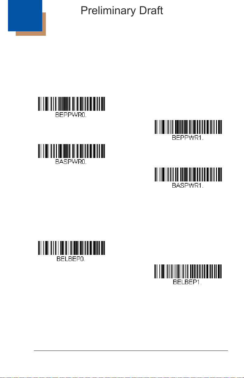
4
Power Up Beeper Off -
Scanner
* Power Up Beeper On -
Scanner
Power Up Beeper Off -
Cordless Base
Power Up Beeper On -
Cordless Base
*Beep on BEL Off
Beep on BEL On
Preliminary Draft
Input/Output Settings
Power Up Beeper
The scanner can be programmed to beep when it’s powered up. If you are
using a cordless system, the base can also be programmed to beep when it is
powered up. Scan the Off bar code(s) if you don’t want a power up beep.
Default = Power Up Beeper On - Scanner.
Beep on BEL Character
You may wish to force the scanner to beep upon a command sent from the host.
If you scan the Beep on BEL On bar code below, the scanner will beep every
time a BEL character is received from the host.
Default = Beep on BEL Off.
4 - 1
Page 92

Trigger Cl ick
Trigger Click On
*Trigger Click Off
* Beeper - Good Read On
Beeper - Good Read Off
Preliminary Draft
To hear an audible click every time the scanner trigger is pressed, scan the
Trigger Click On bar code below. Scan the Trigger Click Off code if you don’t
wish to hear the click. (This feature has no effect on serial or automatic triggering.)
Default = Trigger Click Off.
Good Read and Error Indicators
Beeper – Good Read
The beeper may be programmed On or Off in response to a good read.
Turning this option off, only turns off the beeper response to a good read
indication. All error and menu beeps are still audible.
Good Read On.
Default = Beeper -
4 - 2
Page 93
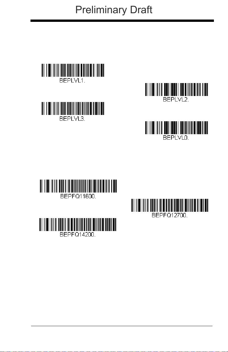
Beeper Volume – Good Read
* High
Medium
Off
Low
Low (1600 Hz)
* Medium (2700 Hz)
High (4200 Hz)
Preliminary Draft
The beeper volume codes modify the volume of the beep the scanner emits
on a good read.
Default = High.
Beeper Pitch – Good Read
The beeper pitch codes modify the pitch (frequency) of the beep the scanner emits on a good read.
Default = Medium.
4 - 3
Page 94
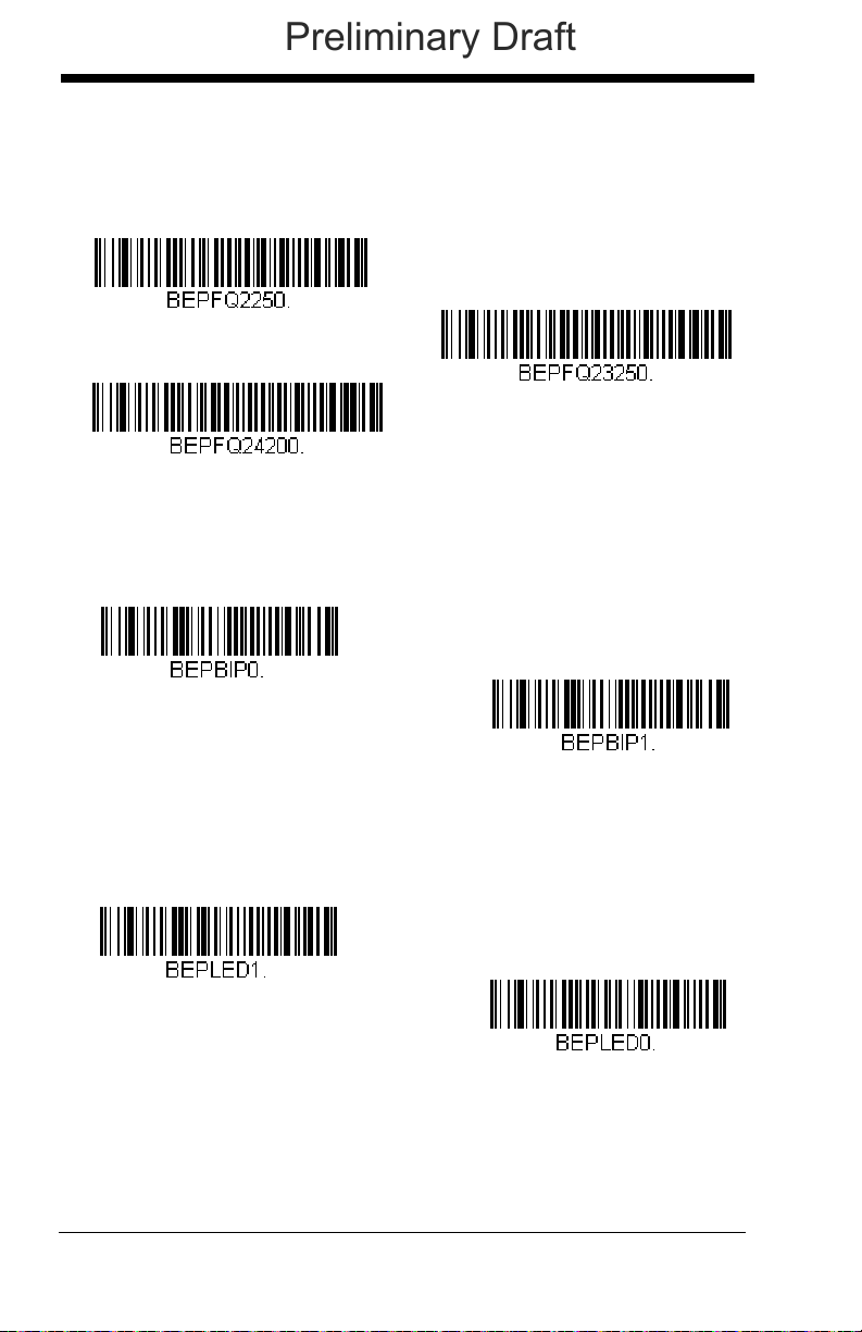
Beeper Pitch – Error
* Razz (250 Hz)
Medium (3250 Hz)
High (4200 Hz)
* Normal Beep
Short BeepShort Beep
* LED - Good Read On
LED - Good Read Off
Preliminary Draft
The beeper pitch codes modify the pitch (frequency) of the sound the scanner emits when there is a bad read or error.
Default = Low.
Beeper Duration – Good Read
The beeper duration codes modify the length of the beep the scanner emits
on a good read.
Default = Normal.
LED – Good Read
The LED indicator can be programmed On or Off in response to a good
read.
Default = On.
4 - 4
Page 95

Number of Beeps – Good Read
Number of Good Read Beeps/LED Flashes
Number of Error Beeps/LED Flashes
Preliminary Draft
The number of beeps of a good read can be programmed from 1 - 9. The
same number of beeps will be applied to the beeper and LED in response
to a good read. For example, if you program this option to have five beeps,
there will be five beeps and five LED flashes in response to a good read.
The beeps and LED flashes are in sync with one another. To change the
number of beeps, scan the bar code below and then scan a digit (1-9) bar
code and the Save bar code on the Programming Chart inside the back
cover of this manual.
Default = 1.
Number of Beeps – Error
The number of beeps and LED flashes emitted by the scanner for a bad
read or error can be programmed from 1 - 9. For example, if you program
this option to have five error beeps, there will be five error beeps and five
LED flashes in response to an error. To change the number of error beeps,
scan the bar code below and then scan a digit (1-9) bar code and the Save
bar code on the Programming Chart inside the back cover of this manual.
Default = 1.
4 - 5
Page 96

Good Read Delay
* No Delay
Short Delay (500 ms)
Medium Delay (1,000 ms)
Long Delay (1,500 ms)
User-Specified Good Read Delay
Preliminary Draft
This sets the minimum amount of time before the scanner can read another
bar code.
Default = 0 ms (No Delay).
User-Specified Good Read Delay
If you want to set your own length for the good read delay, scan the bar
code below, then set the delay (from 0-30,000 milliseconds) by scanning
digits from the inside back cover, then scanning Save.
Manual/Serial Trigger Modes
Manual Trigger
When in manual trigger mode, the scanner scans until a bar code is read,
or until the trigger is released. Two modes are available, Normal and
Enhanced. Normal mode offers good scan speed and the longest working ranges (depth of field). Enhanced mode will give you the highest possi-
4 - 6
Page 97

ble scan speed but slightly less range than Normal mode. Enhanced mode
* Manual Trigger - Normal
Manual Trigger - Enhanced
Read Time-Out
Preliminary Draft
is best used when you require a very fast scan speed and don’t require a
long working range.
Serial Trigger
You can activate the scanner either by pressing the trigger, or using a serial
trigger command (see Trigger Commands on page 11-4). When in serial
mode, the scanner scans until a bar code has been read or until the deactivate command is sent. The scanner can also be set to turn itself off after a
specified time has elapsed (see Read Time-Out, which follows).
Read Time-Out
Use this selection to set a time-out (in milliseconds) of the scanner’s
trigger when using serial commands to trigger the scanner. Once the
scanner has timed out, you can activate the scanner either by pressing
the trigger or using a serial trigger command. After scanning the Read
Time-Out bar code, set the time-out duration (from 0-300,000 milliseconds) by scanning digits on the Programming Chart inside the back
cover, then scanning Save.
Default = 30,000 ms.
Scanner Power Time-Out Timer
Note: Scanner Power Time-out Timer only applies to cordless systems.
It does not apply to corded scanners.
When there is no activity within a specified time period, the scanner
enters low power mode. Scan the appropriate scanner power time-out
bar code to change the time-out duration (in seconds).
Note: Scanning zero (0) is the equivalent of setting no time-out.
4 - 7
Page 98
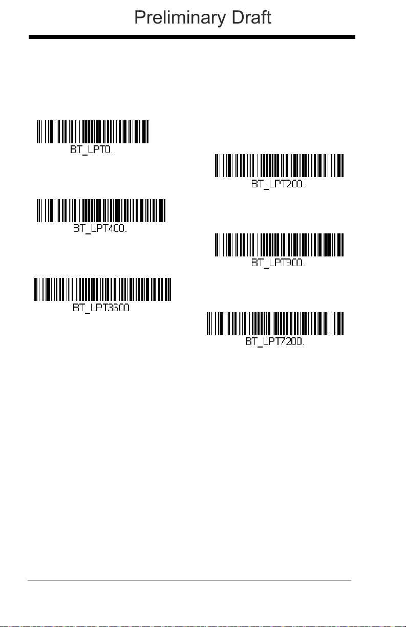
If there are no trigger pulls during the timer interval, the scanner goes
0 seconds
200 seconds
400 seconds
900 seconds
* 3600 seconds
7200 seconds
Preliminary Draft
into power down mode. Whenever the trigger is enabled, the timer is
reset. If the scanner is placed in the charge base cradle and the battery is in the process of being charged, the scanner will not go into
power down mode.
Default = 3600 seconds.
Note: When the scanner is in power down mode, pull the trigger to
power the unit back up. There will be a set of power up beeps
and a delay of up to a few seconds for the radio to join. The
scanner will then be ready to use.
In-Stand Sensor Mode
This feature senses when the scanner is removed from the stand and tells it to
begin manual triggering. When you scan Sensor On, the scanner goes into
manual trigger mode when it is removed from the stand. For example, if the
4 - 8
Page 99

scanner is programmed for Presentation Mode (page 4-9), it would be in pre-
* Sensor On
Sensor Off
Presentation Mode
* LEDs On
LEDs Off
Preliminary Draft
sentation mode whenever it is in the stand, and in manual trigger mode whenever it is removed from the stand.
Default = Sensor On.
Presentation Mode
Presentation Mode uses ambient light to detect bar codes. The LEDs remain
off until a bar code is presented to the scanner, then the LEDs turn on automatically to read the code. If the light level in the room is not high enough, Presentation Mode may not work properly.
Note: If you are using a cordless device in Presentation Mode, the battery will
not charge unless the power supply is plugged into the base’s auxiliary
power port.
Presentation LED Behavior after Decode
When a scanner is in presentation mode, the LEDs remain on and continue
scanning for a short time after a bar code is decoded. If you wish to turn
the LEDs off immediately after a bar code is decoded, scan the LEDs Off
bar code, below.
Default = LEDs On.
4 - 9
Page 100

Presentation Sensitivity
Sensitivity
Streaming Presentation Mode
- Normal
Streaming Presentation Mode
- Enhanced
Preliminary Draft
Presentation Sensitivity is a numeric range that increases or decreases the
scanner's reaction time to bar code presentation. To set the sensitivity,
scan the Sensitivity bar code, then scan the degree of sensitivity (from 0-
20) from the inside back cover, and Save. 0 is the most sensitive setting,
and 20 is the least sensitive.
Default = 1.
Streaming Presentation™ Mode
When in Streaming Presentation mode, the scanner’s aimer goes out after a
short time, but the scan illumination remains on all the time to continuously
search for bar codes. Two modes are available, Normal and Enhanced. Normal mode offers good scan speed and the longest working ranges (depth of
field). Enhanced mode will give you the highest possible scan speed but
slightly less range than Normal mode. Enhanced mode is best used when you
require a very fast scan speed and don’t require a long working range.
When using Preferred Symbology (page 4-16), a lower priority symbol must be
centered on the aiming pattern to be read in Streaming Presentation Mode.
Note: If you are using a cordless system, the base must have an external power
supply plugged into the aux port for Streaming Presentation to work
properly.
4 - 10
 Loading...