

Page 1
March 29, 2019 1 31-00198—01
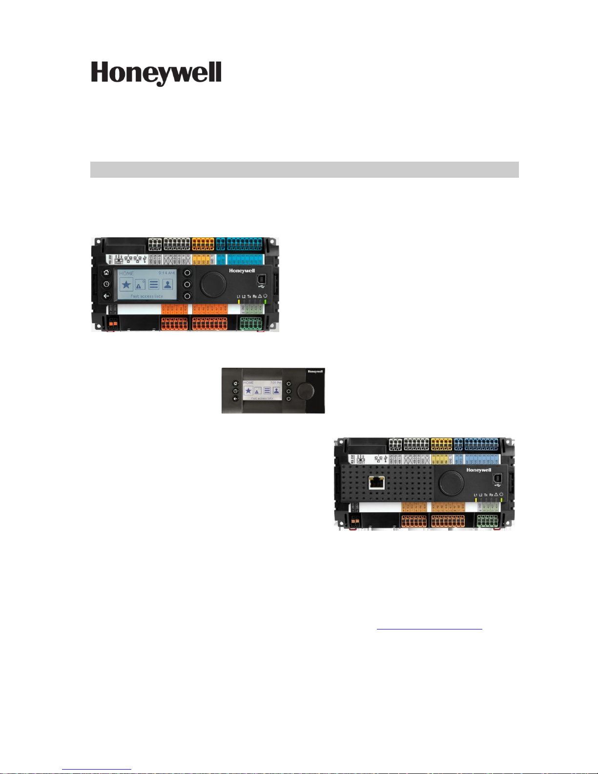
CIPer MODEL 50 CONTROLLER
USER GUIDE
IMPORTANT NOTE: Email your Host Id to Honeywell WEBs Customer Care (websliense@honeywell.com), so we
can move the license to your organization. For additional queries contact to the distributor.
Page 2

WEBs CIPer MODEL 50 – USER GUIDE
31-00198—01 2
TABLE OF CONTENTS
Order numbers (SKU) ................................................................................................................................................................................................4
HMI configuration principles .........................................................................................................................................................................4
HMI service ..............................................................................................................................................................................................................5
HMI pin ......................................................................................................................................................................................................................7
HMI user rights ......................................................................................................................................................................................................8
HMI PIN lock-out ..................................................................................................................................................................................................9
Enabling the alarming on the HMI ........................................................................................................................................................... 10
Enabling the alarm LED on the HMI ....................................................................................................................................................... 10
Adjusting alarm poll-rate for the HMI ..................................................................................................................................................... 11
Local language HMI menus - translation ............................................................................................................................................. 12
Login user into the HMI and control the translation ....................................................................................................................... 13
Filling the Fast Access Lists ......................................................................................................................................................................... 13
Setting the time format on the home screen ...................................................................................................................................... 15
Onboard Inputs and Outputs ............................................................................................................................................................................ 16
Dual Ethernet ............................................................................................................................................................................................................. 17
Separated networks .......................................................................................................................................................................................... 17
Network switching mode ....................................................................................................................................................................... 18
Combined network switching & separated networks ............................................................................................................. 19
Front USB/Ethernet interface ..................................................................................................................................................................... 19
Secure Boot – Increased Cyber Security ................................................................................................................................................ 21
Part numbers and supporting material .................................................................................................................................................. 22
Performance ........................................................................................................................................................................................................ 23
Performance tests ............................................................................................................................................................................................. 23
Panel-Bus capacity .................................................................................................................................................................................. 23
Panel-Bus Communication tuning .................................................................................................................................................. 24
Panel-Bus cable type and length ..................................................................................................................................................... 25
Compatibility .............................................................................................................................................................................................................. 26
WEBs compatibility .......................................................................................................................................................................................... 26
Spyder & Stryker tool compatibility .......................................................................................................................................................... 26
3rd party modules ............................................................................................................................................................................................. 26
CIPer Model 50 specific modules ............................................................................................................................................................. 27
Web-Browser compatibility .......................................................................................................................................................................... 29
Input/Output module compatibility ........................................................................................................................................................ 29
CIPer Model 50 Firmware .............................................................................................................................................................................. 30
Firmware & Hardware compatibility ................................................................................................................................................ 30
Firmware upgrade..................................................................................................................................................................................... 30
How to Restore the CIPer Model 50 – Installation of the “Clean Dist” file............................................................................ 31
Reset CIPer Model 50 controller credentials ....................................................................................................................................... 33
Technical Documentation ............................................................................................................................................................................ 34
Appendix ....................................................................................................................................................................................................................... 35
Page 3

WEBs CIPer Model 50 – USER GUIDE
3 31-00198—01
USB Driver Installation for Windows 7 .................................................................................................................................................... 35
USB Driver Installation for Windows 8 .................................................................................................................................................... 40
USB Driver Installation for Windows 10 ................................................................................................................................................. 44
Page 4
WEBs CIPer MODEL 50 – USER GUIDE
31-00198—01 4
Order numbers (SKU)
The onboard HMI is featured in the below listed order numbers:
• WEB-EAGLENX26D
• WEB-EAGLENX26ND
IMPORTANT:
To make efficient use of HMI functionality, it is required to do a few set-up steps in Honeywell WEBStation
N4.4.93.40.8 or higher. Refer section “HMI configuration principles” given below.
• WEB-EAGLENX26D
The XL2000HMI can be connected and operated with the below listed OS (SKU) numbers.
• WEB-EAGLENX26ND
HMI configuration principles
To get the onboard HMI or detached HMI operational, the following configuration principles need to be done
in WEBs N4:
1. Add & enable the HMI Service.
2. Set the PIN for the HMI access.
3. Add HMI and LED Alarm recipients.
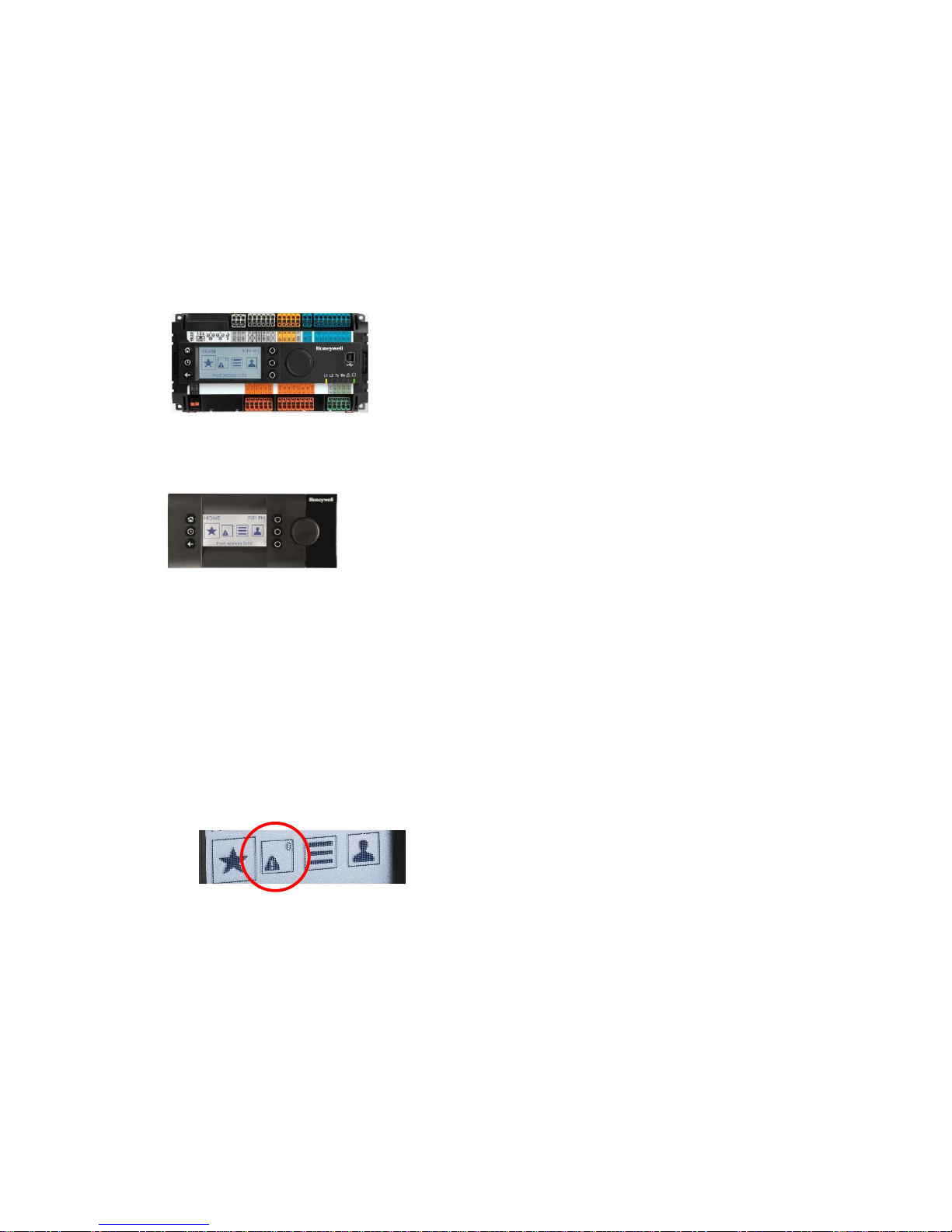
NOTE: As long as there are un-acknowledged alarms in the station, the alarm symbol will be blinking,
regardless if a user is logged-in to the HMI or not. See below picture:
4. Configure the alarming for the HMI.
5. Fill the Fast Access Lists (FAL) with data-points, schedules & parameters.
6. If desired, create a custom HMI sequence.
Page 5
WEBs CIPer Model 50 – USER GUIDE
5 31-00198—01
HMI service
The onboard and detached HMI will only work when the HMI Service, called
“HonEagleHawkHmiService” has been placed into “Services” of your station.
Important:
Always place the “HonEagleHawkHmiService” into the “Services” folder.
Do NOT place it under any service within “Services”.
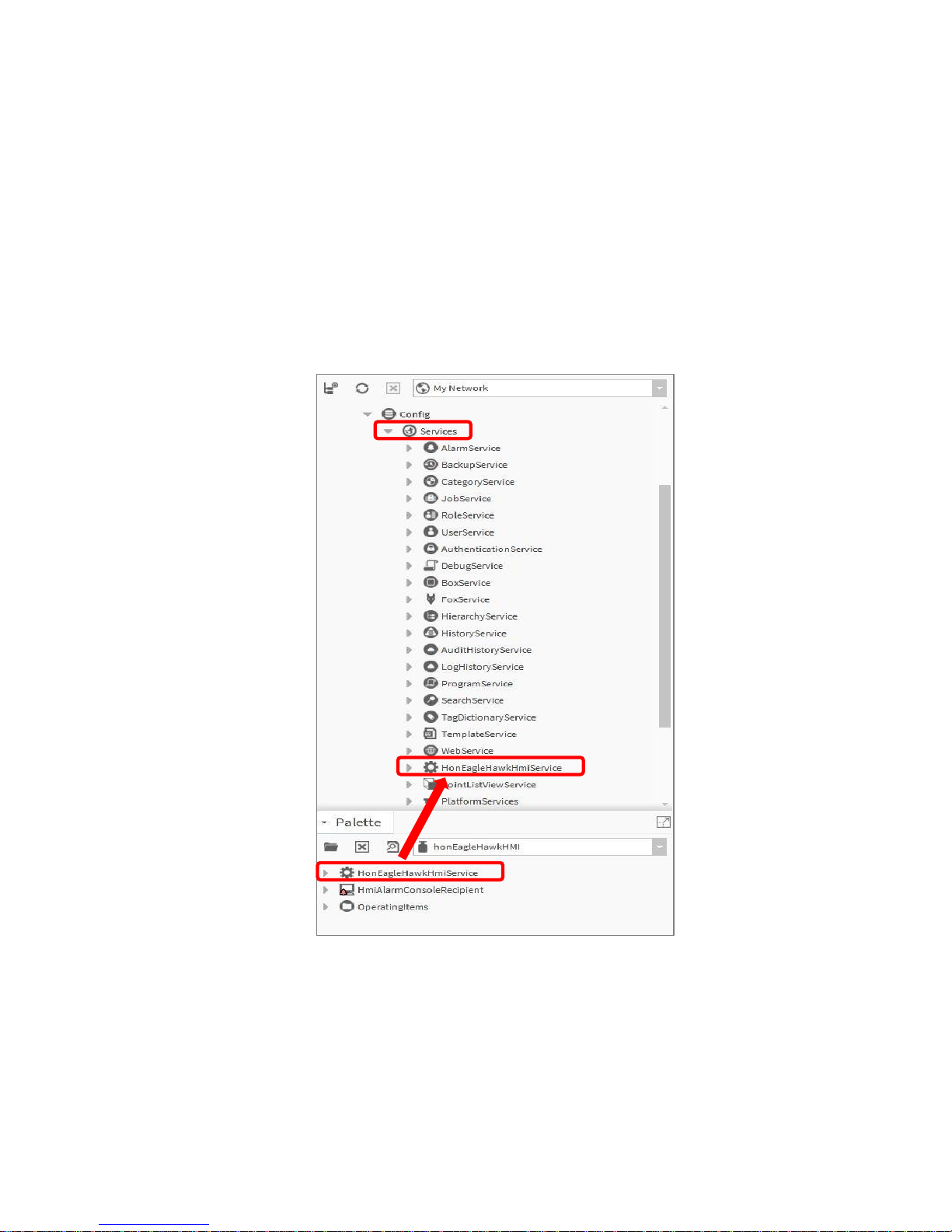
Step 1:
Select the “honEagleHawkHMI” palette and drag the “HonEagleHawkHmiService” into “Services” of
your station.
Page 6
WEBs CIPer MODEL 50 – USER GUIDE
31-00198—01 6
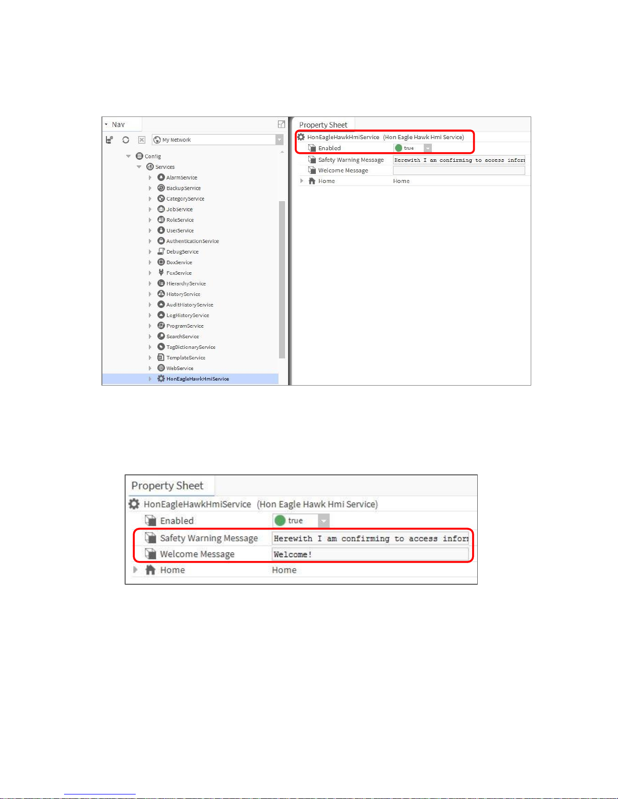
Step 2:
Enable the “HonEagleHawkHmiService”.
Step 3:
Changing, deleting or translating the messages on the HMI.
Changing or deleting can be done in the property sheet of the HMI Service – see below:
Page 7

WEBs CIPer Model 50 – USER GUIDE
7 31-00198—01
For translating the “Warning” and “Welcome” message of the HMI, you can also use the WEBs N4
Lexicon tool, see section “Local language HMI menus – translation” in this bulletin
HMI pin
PIN, PIN-configuration and log-off definition is fully integrated in the Niagara “User Service”. This makes it
secure and allows to re-use the user definitions already in place for the station.
NOTE: It is mandatory to enter a 5-digit (Numeric only) PIN here. For security reasons, there is no
default PIN.
If the PIN is not present, the controller will not function.
Page 8
WEBs CIPer MODEL 50 – USER GUIDE
31-00198—01 8
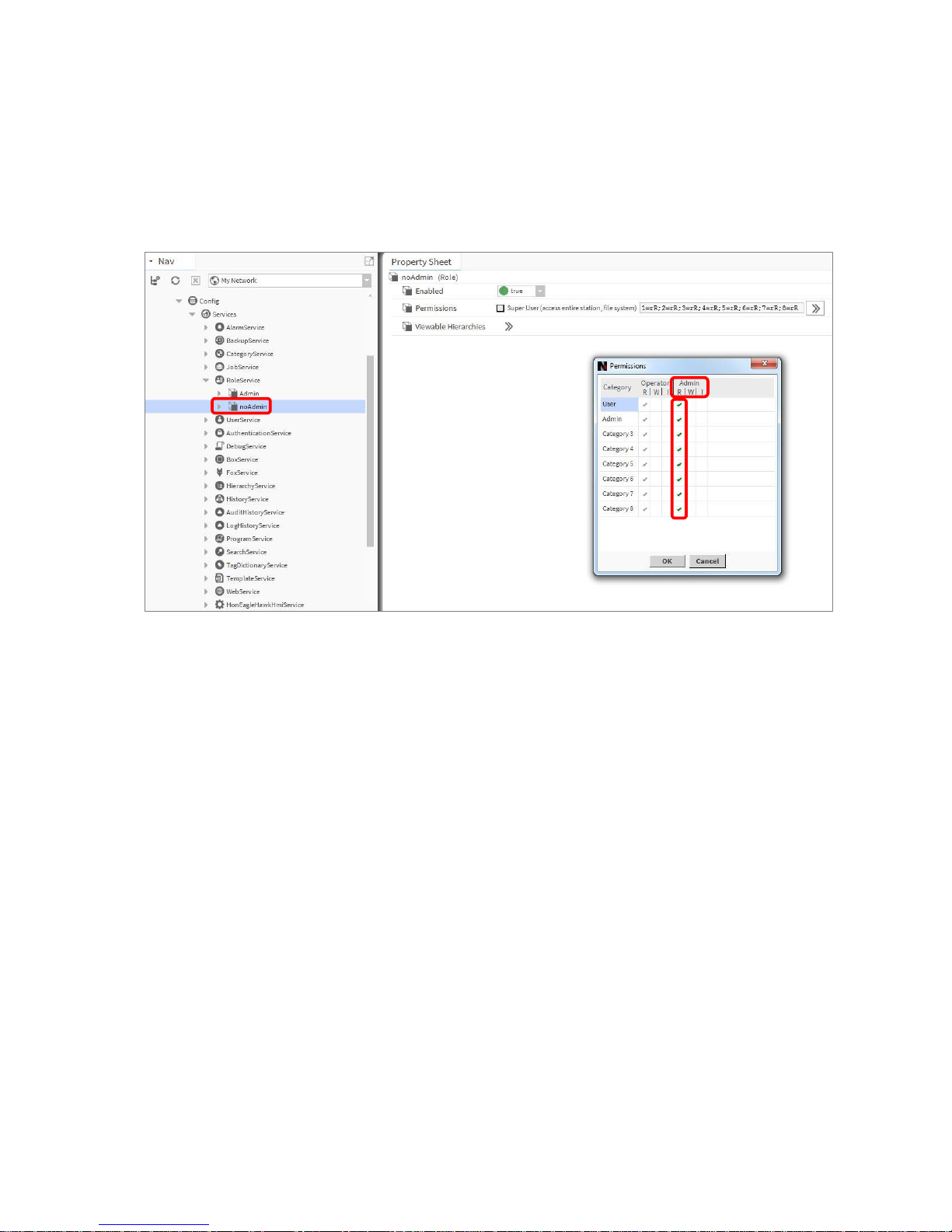
HMI user rights
In the Admin column (marked red) for the user permissions of the RoleService, it is mandatory to enable “Read”
rights to the categories you want access via HMI, otherwise the user will have no access.
You may also provide the “Write” and “Invoke” rights to a catogory as required.
.
Page 9
WEBs CIPer Model 50 – USER GUIDE
9 31-00198—01
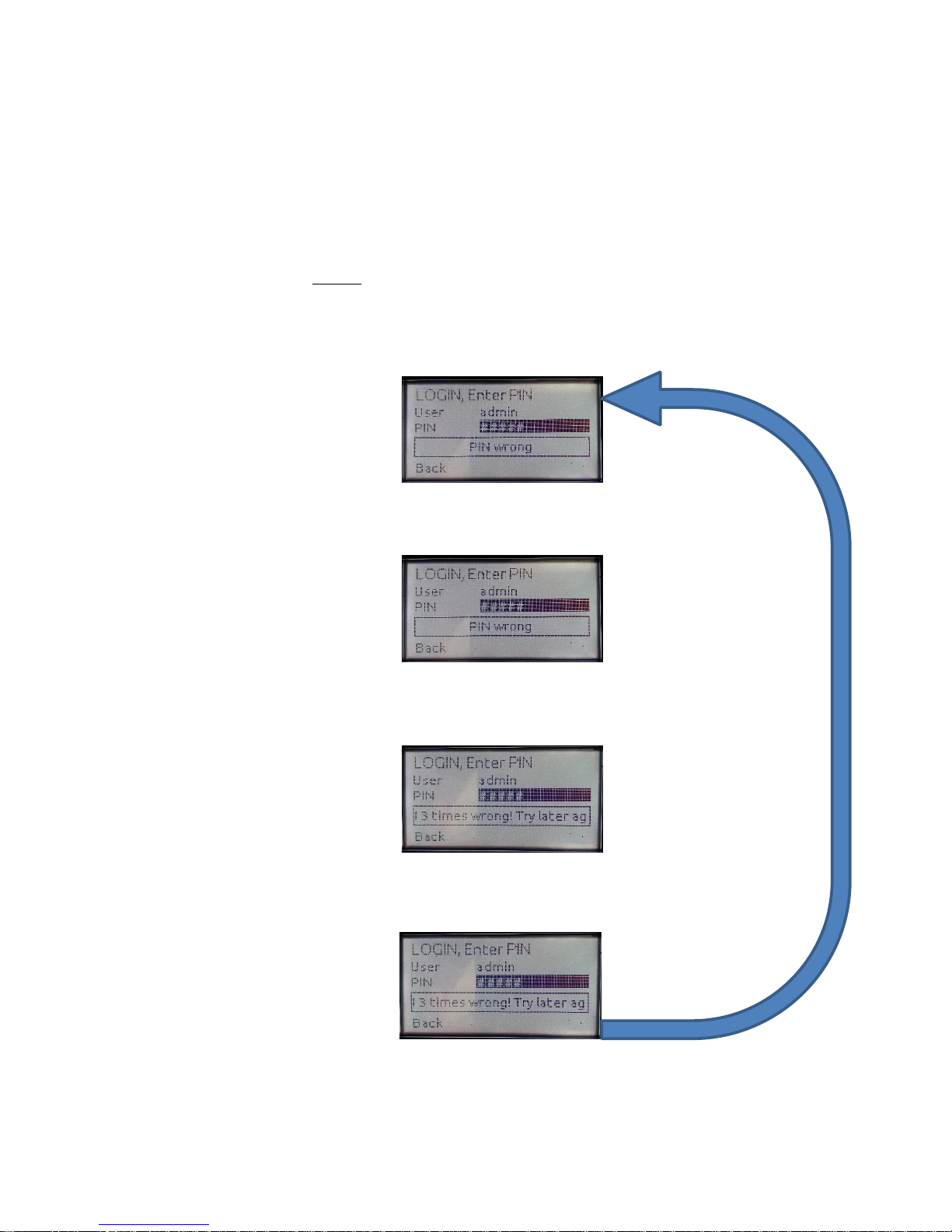
HMI PIN lock-out
For Cyber Security reasons, users will be locked-out after multiple entries of a wrong PIN:
• After three wrong PIN entries in a row, user login is blocked for 1 min. For each wrong PIN after this, the
user must wait for 1 min.
• This time sequence is repeated until a successful login is done.
NOTE:
For Cyber Security reasons, all users are blocked during the waiting time.
This is an intentional behavior.
1st time wrong PIN:
2nd time wrong PIN:
3rd time wrong PIN:
Wait time is 1 minute for all users.
4
th
/ 5th / 6th / … etc time wrong PIN:
Correct PIN entry will restart the lock-out sequence.
Page 10
WEBs CIPer MODEL 50 – USER GUIDE
31-00198—01 10
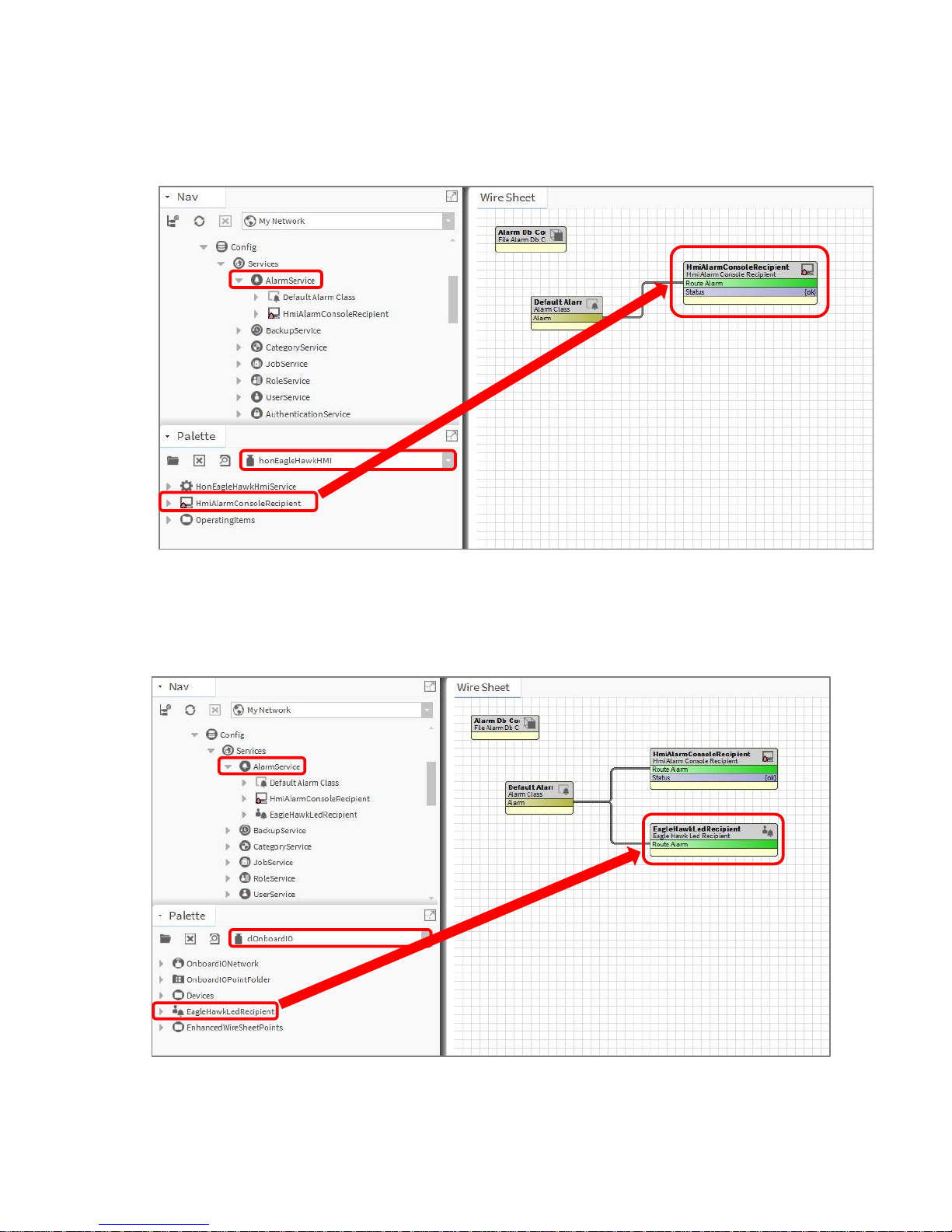
Enabling the alarming on the HMI
From the “honEagleHawkHMI” palette, drag the “HmiAlarmConsoleRecipient” into the “Alarm
Service” and connect it to the “Default Alarm Class”.
Enabling the alarm LED on the HMI
From the “clOnboardIO” palette, drag the “EagleHawkLedRecipient” into the “Alarm Service” and
connect it to the “Default Alarm Class”:
Page 11

WEBs CIPer Model 50 – USER GUIDE
11 31-00198—01
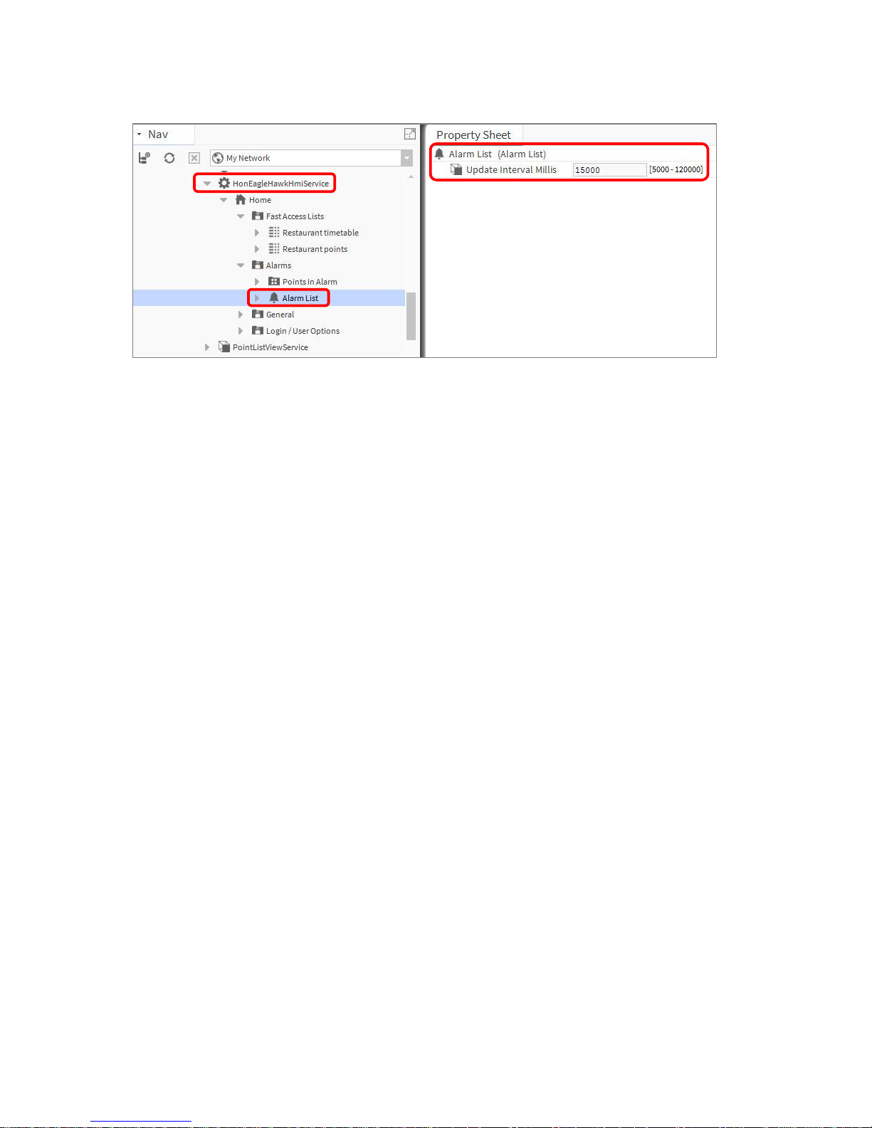
Adjusting alarm poll-rate for the HMI
The update rate for alarms and data-points on the HMI has a default setting.
This can be adjusted with the CPU performance, to balance the information demand.
IMPORTANT:
I) The faster the alarm and data-point poll rate, the more impact it will have on the performance of
the station. This might slower the CPU or station performance.
II) Default setting for alarm and data-point poll-rate is 15s (15.000 millisecond).
III) Adjustable range is from 5s to 120s (5.000…120.000 millisecond).
IV) By default, the poll-rate setting is hidden and can be made visible in the Slot Sheet.
When adjusting for faster polling, watch the CPU load of the station.
To change the alarm poll rate, select the alarm menu item and select the Slot Sheet:
Right click the “updateIntervalMillis” and uncheck the “Hidden” flag.
Page 12
WEBs CIPer MODEL 50 – USER GUIDE
31-00198—01 12
Double-click the Alarm List in “HonEagleHawkHmiService” and change the poll-rate as appropriate.
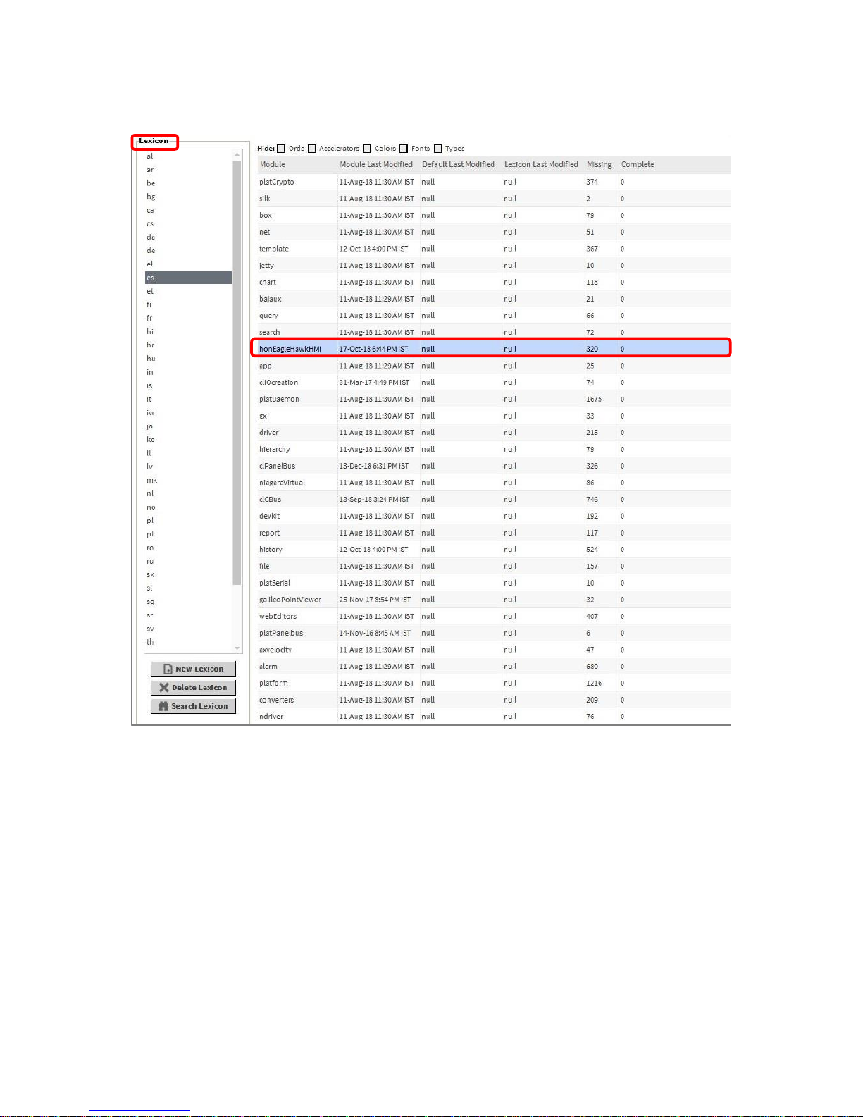
Local language HMI menus - translation
The HMI menus can be localized by making use of the standard Lexicon tool of WEBs N4:
- Open Lexicon tool of WEBs N4 and your local language lexicon file
- Open the “honEagleHawkHMI module
- Do the translations and save this lexicon file
- Commission the lexicon file into the controller
- Generate a new user which uses the new language file
Page 13
WEBs CIPer Model 50 – USER GUIDE
13 31-00198—01
Login user into the HMI and control the translation
Filling the Fast Access Lists
To fill the Fast Access Lists (FAL) with points, parameters and schedules, you have two options:
Option 1: Drag and drop points from the Navigation tree on the left into the Fast Access List on the property
sheet on the right.
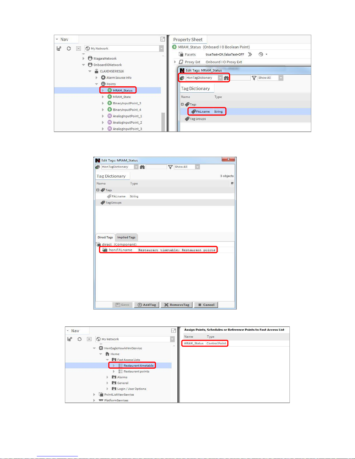
Option 2: Use tagging: Drag and Drop “HonTagDictionary” into the “TagDictionaryService”. Select the point(s)
you want to add, open the tag dialog, select the “HonTagDictionary” and select the tag “FALname”.
Page 14
WEBs CIPer MODEL 50 – USER GUIDE
31-00198—01 14
In the attached tag, add the name of the Fast Access List(s) you want to have this data point represented in.
Separate multiple Fast Access Lists by using a semicolon “;”.
Page 15

WEBs CIPer Model 50 – USER GUIDE
15 31-00198—01
Setting the time format on the home screen
Step 1:
Make sure that the Lexicon of the desired local language is installed. If not, use the Lexicon Installer
to install it.
Step 2:
Set the language in the Station/PlatformService “locale” field.
Page 16

WEBs CIPer MODEL 50 – USER GUIDE
31-00198—01 16
Onboard Inputs and Outputs
Onboard
Inputs/Outputs
Description
Max.
cable
length
WEBEAGLENX26D
WEBEAGLENX26ND
UI
(Universal
Input)
NTC10kΩ (Type II), NTC20kΩ,
0…10V, slow BI 0.4 Hz
Short-circuit protected against
24VAC
1200 ft 8 8
NTC10kΩ (Type II), NTC20kΩ,
0…10V fix pull-up, slow BI 0.4 Hz
Short-circuit protected against
24VAC
1200 ft 2 2
BI
(Binary Input)
open = 24 VDC, closed 2.0 mA,
totalizer @ 15 Hz max.
Short-circuit protected against
24VAC
1200 ft 4 4
AO
(Analog Output)
0..11 V (max. 1 mA)
1200 ft 4 4
BO
(Binary Output)
Relay Normally Open contact 3A,
250VAC, 30VDC
1200 ft 4 4
Relay Normally Open contact 10A,
250VAC, 30VDC
1200 ft 1 1
Relay Normally Open contact with
one common
1200 ft 3 3
For all technical details on Onboard Inputs/Outputs, please refer to the CIPer 50 Product Datasheet
(31-00197-01) and CIPer 50 Installation & Commissioning Instructions (31-00233EFS).
Page 17

WEBs CIPer Model 50 – USER GUIDE
17 31-00198—01
Dual Ethernet
The CIPer Model 50 is equipped with a Dual Ethernet interface.
All information about the Dual Ethernet can be found in the CIPer 50 Installation & Commissioning Instructions
(31-00233EFS).
Separated networks
SEPARATED NETWORKS = DEFAULT SETTING
For cyber security reasons, the default setting of the Dual Ethernet is with the following IP settings:
• Ethernet port 1: IP address 192.168.200.20, subnet 255.255.255.0
• Ethernet port 2: IP address 192.168.201.20, subnet 255.255.255.0
Page 18

WEBs CIPer MODEL 50 – USER GUIDE
31-00198—01 18
Network switching mode
Optionally, the Dual Ethernet can be operated in network switching mode.
If this mode is desired, disable one of the Ethernet ports in Niagara – see screenshot below.
Typical application scenarios are a closed BMS networks, like for daisy-chaining plant controllers
or daisy-chaining room controllers on Ethernet.
NOTE: The switching functionality will not work during power-fail of the CIPer 50 controller.
Important: Set a gateway address
For the Ethernet switching functionality to work, it is mandatory that you enter a Gateway address.
If there is no gateway in the subnet, then use a gateway address that relates to the IP address of the Ethernet
adapter that is enabled.
In the screenshot below, the gateway address is 192.168.1.1, hence the IP address of Ethernet adapter 1 must
be in the range of 192.168.1.2 to 192.168.1.255.
Page 19

WEBs CIPer Model 50 – USER GUIDE
19 31-00198—01
Combined network switching & separated networks
Optionally separating networks and switching functionality can be combined.
This allows to have one (or more) controllers connected to the customer intranet, and all other controllers
residing in a closed BMS network.
A typical application is the supervisory controller(s) accessible from the customer intranet, and the room
controllers residing in a closed network, and thus being not directly accessible from the customer intranet.
Front USB/Ethernet interface
All details regarding installation and commissioning of the CIPer Model 50 can be found within the Installation
& Commissioning Instructions 31-00233EFS.
All models of the CIPer Model 50 controller are equipped with a USB 2.0 Device interface at the front, which is
an Ethernet over USB connection.
The permanent IP address of this USB interface is 192.168.255.241.
This interface allows connection of WEBs N4 for programming and operation, and for web browsers or 3rd-party
touch panels.
If your WEBs N4 PC or your web browser does not connect to this USB interface, the WINDOWS driver may be
missing. In this case, please see APPENDIX chapters “USB Driver Installation for Windows 7”, “USB Driver
Installation for Windows 8” “USB Driver Installation for Windows 10” installation for WINDOWS 7/8/10”.
Page 20

WEBs CIPer MODEL 50 – USER GUIDE
31-00198—01 20
ATTENTION:
Due to the risk of short-circuiting (see figure above), it is strongly recommended that the CIPer Model 50
controller be supplied with power from a dedicated transformer.
However, if the Model 50 controller is to be supplied by the same transformer powering other controllers or
devices (e.g., the PW M-Bus Adapter), care must be taken to ensure that correct polarity is observed.
Page 21

WEBs CIPer Model 50 – USER GUIDE
21 31-00198—01
Secure Boot – Increased Cyber Security
The CIPer Model 50 is an IIoT (Industrial Internet of Things) device.
Its benefits and typical deployments include network access as well as browser access via Intranet and Internet.
Beginning with the firmware of this release, the CIPer Model 50 will only boot and run authenticated WEBs N4
firmware. This is achieved by a firmware signature.
To achieve the best possible cyber security, please note the following:
1) Read and apply the Honeywell General Best Practices (31-00129), which you will find
on the WEBs Building Forum
2) It is not possible to downgrade the released WEBs N4 firmware to a previous and older
firmware version due to Cyber Security reasons.
3) Operate controllers either in internal networks, or use a coded VPN connection for
internet access, to limit attacks from external Internet users.
4) Recommend your customers (network domain owners) to make use of HTTPS for
secure web-browser access to the controller.
5) Recommend your customers (network domain owners) to obtain a certificate from a
Certification Authority, and download this certificate into the controller.
6) If a web-access outside a VPN is to be realized, it should be handled through a firewall
with appropriate “Whitelisting”, although a VPN is strongly recommended, because it is the
best way to provide secure and encrypted communications to the controller.
7) Close all ports on the Internet router/gateway, and only open those ports that are
mandatory for operation or maintenance, to minimize the attack surface.
8) BACnet (e.g. port 47808) should never be exposed to the Internet, not even through a
firewall, but should only be exposed on internal networks or via a VPN, because the BACnet
protocol does not have security built-in.
9) Never use the default passwords, because they are widely available and are therefore
easily guessed.
10) Use “strong” passwords, because modern password "crackers" can break simple
passwords in a matter of minutes.
11) Never operate CIPer controllers unprotected on open Internet.
NOTE: “Whitelisting” stands for allowing explicit IP-Addresses or MAC addresses of dedicated and trusted PCs
to access the controller behind the firewall and router.
Page 22

WEBs CIPer MODEL 50 – USER GUIDE
31-00198—01 22
Part numbers and supporting material
Part Number
(SKU)
Description
Built-in IO
points
Built-in
HMI
WEBEAGLENX26ND
100 Global Points (Panel-bus, on-board I/O)
+10 Analytics Points + WEBS N4 Software
Maintenance Agreement
26
-
WEBEAGLENX26D
26
Yes
EAGLEH255PUP
255 Additional Panel-bus Expansion I/O Points
PIN-DEV-UP-1
+1 Device and +50 Global points (LON, Modbus, Panelbus, etc.)
TPU-11-01
Spare part for WEB-EAGLENX26ND and WEB-EAGLENX26D. Removable
terminal plugs: push-in type; set of 3 plugs;
TPU-45-01
Spare part for WEB-EAGLENX26D and ND: Removable terminal plugs; push-in
type; set of 9 plugs;
XS831
Set of 10 terminals for converting 0…20mA signals to 0…10VDC: Each set
consists of two groups of four pairs of push-in terminals, each with a 499 Ohm
resistor.
MVC-80-AC1
Terminal cover. Package of ten. Color RAL 9011
MVC-80-AC2
Door mounting frame. Package of ten. Color RAL 9011
MVC-40-AC3
Cabling strain relief. Package of ten.
Page 23

WEBs CIPer Model 50 – USER GUIDE
23 31-00198—01
Performance
Performance tests
The system boundaries are hard to define, as they depend on many factors, such the boundaries of
the hardware performance in general, the network performance, the “traffic” created by the
application, concurrent polls from Supervisors, Station Save intervals, Recovery Service intervals,
etc.
In addition to the general Tridium guidance of a maximum of 80% CPU load, Honeywell has
undertaken two exemplary performance tests.
The maximum recommended CPU usage is outlined in the two tables below.
no. of
modules
no. of
hardware
I/O points
points in
PX pages
freq. of
value
changes
histories
enabled
CPU usage
test result
Panel Bus (via
RS485-1)
46(A
491
491(B
2 sec
(poll rate)
--
30%
(occasionally:
50%)
OK for noncritical
applications
(C
BACnet
MS/TP (via
RS485-2)
13
559
559(D
2 sec
(COV)
(E
500
(A
9x 821A, 9x 822A, 9x 823A, 9x 824, 5x 825, 5x 830A
(B
Four (4) PX pages: AI, AO, BI, and BO points each in a dedicated PX page per point type
(C
About 0.5% of the BACnet MS/TP point updates are occasionally delayed.
(D
One (1) PX page with all points
(E
COV: Change of Value. COV frequency is rate of change in the value of an object property.
COV frequency
max. no. of COV updates per min.
across RS485-1 and RS485-2
together
CPU usage
test result
BACnet MS/TP at
38,500 bps
4 sec
4,000
25…35%
(occasionally:
60%)
OK
Panel-Bus capacity
128 Panel-Bus IO modules per CIPer Model 50 are supported:
Up to 64 Panel-Bus IO modules on RS485-1
• Max. 16 IO modules per type
Example 1:
16x XF830A + 16x XF821A + 16x XF823A + 16x XF824A
Example 2:
10x + 12x XF821A + 12x XF822A, + 12x XF823A + 12x XF824A + 6x XF825A
Up to 64 Panel-Bus IO modules on RS485-2
• Max. 16 IO modules per type
Example 1:
16x XF830A + 16x XF821A + 16x XF823A + 16x XF824A
Example 2:
10x + 12x XF821A + 12x XF822A, + 12x XF823A + 12x XF824A + 6x XF825A
Page 24

WEBs CIPer MODEL 50 – USER GUIDE
31-00198—01 24
Panel-Bus Communication tuning
The default polling time for all Panel-Bus points is set to “Normal = 10s”.
This means that the data from the field are updated every 10s.
Write commands are sent without time delay.
The polling frequency can be changed, and we do recommend that it must be updated more frequently.
Important: For CIPer Model 50, the fastest poll rate is 200 milliseconds.
Do NOT set a faster poll-rate, as this may overload the CPU in larger systems.
Editing the standard polling frequency can be done inside the “Poll Scheduler” of the Property
Sheet of the PanelbusNetwork:
Page 25

WEBs CIPer Model 50 – USER GUIDE
25 31-00198—01
The Assignment of the different Poll Intervals for each point is done inside the Panelbus Point Discovery Dialog.
Panel-Bus cable type and length
See CIPer Model 50 Installation and Commissioning Instructions 31- 00233EFS for all details.
Max. Panel Bus length:
120 ft for any type of cabling and topology. No additional end termination is permitted.
2400 ft for twisted-pair or telephone cable and daisy chain topology. The Controller must be
positioned at one end of the Panel-Bus, and an end termination (120 Ω) at the other end.
Furthermore, the three-position slide switch must be set to "END." Use Honeywell cable 3322 or
3251.
Page 26

WEBs CIPer MODEL 50 – USER GUIDE
31-00198—01 26
Compatibility
WEBs compatibility
N4.4U2 is mandatory for CIPer Model 50, also the related jar-files and modules in order to run the
CIPer 50 with HMI. Downloaded the workbench version N4.4.93.40.8 from the WEBs Building
Forum.
For compatibility of WEBs N4, please refer to the WEBs N4.4.93.40.8 Release Bulletin.
Spyder & Stryker tool compatibility
The Spyder tool is not supported on CIPer Model 50. Configured Spyder controllers LON and/or BACnet can
be integrated. They are supported as 3rd party LON and BACnet devices.
3rd party modules
Support and distribution of Niagara 4 modules that have been developed and distributed by 3rd
party companies lie with these 3rd party companies.
Page 27

WEBs CIPer Model 50 – USER GUIDE
27 31-00198—01
CIPer Model 50 specific modules
The following modules are CIPer Model 50 specific:
Module
Version
Available
from
How to install
into WEBs N4
honEagleHawkHMI-rt.jar
honEagleHawkHMI-wb.jar
honEagleHawkHMI-ux.jar
honTagDictionary-rt.jar
4.4.92.2.1.11
Honeywell
Buildings
Forum
1) Shut-down Model 50
2) Copy the *.jar files into the folder
“c:\Honeywell\WEBStation-N4-
4.4.93.40.30\modules\” on your PC
where the Niagara N4 installation
resides
3) Restart Niagara N4 and the platform
4) Run the “software manager” and
“update all out-of-date” files.
5) Start station
clIOCreation-rt.jar
clIOCreation-wb.jar
4.4.73.24.1.6
clOnboardIO-rt.jar
clOnboardIO-wb.jar
4.4.92.2.10
clPanelBus-rt.jar
clPanelBus-wb.jar
4.4.92.2.1.14
platPanelbus-rt.jar
4.4.73.24.1.8
clean-dist-honeywellnxubc.dist
clCBus-rt.jar
4.4.92.2.1.1
clCBus-ux.jar
4.4.73.24.1.9
clCBus-wb.jar
4.4.92.2.1.1
Page 28

WEBs CIPer MODEL 50 – USER GUIDE
31-00198—01 28
WEBs N4 Driver compatibility
Supported Drivers
Protocol
Default Port
NOTE: For Cyber Security
reasons, all ports ranging 1024 or
lower cannot be used for services
on the device.
Hardware Interface(s)
Platform Daemon
3011
Ethernet RJ45, IP via USB-B
Platform Daemon SSL
5011
Ethernet RJ45, IP via USB-B
Station (FOX)
1911
Ethernet RJ45, IP via USB-B
Station Secure (FOXS)
4911
Ethernet RJ45, IP via USB-B
HTTP *
80
Ethernet RJ45, IP via USB-B
BACnet/IP
47808
Ethernet RJ45
Email alarming, SMTP
25, 587 (check Email provider)
Ethernet RJ45
TCP/IP
N/A
Ethernet RJ45, IP via USB-B
SSH
N/A
Not supported
SNMP
10161, 10162
Ethernet RJ45
SMS
Check SMS provider
Ethernet RJ45
MQTT
1883
Ethernet RJ45
MQTT Secure
8883
Ethernet RJ45
KNX EIBnet/IP
3671
Ethernet RJ45
LON IP
2540, 2541
Ethernet RJ45
Modbus TCP
502
Ethernet RJ45
oBIX
80 or 8443
Ethernet RJ45
Open ADR
Check customer System Admin
(e.g. 80, 8443, 5222, 5223, 5269,
5280)
Ethernet RJ45
EnOcean
Check customer System Admin
Ethernet RJ45
Fidelio FIAS MICROS protocol
Check customer System Admin
Ethernet RJ45
C-Bus Driver (SUSI)
2499
Ethernet RJ45
BACnet MSTP
N/A
RS485-1, RS485-2
Panel-Bus
N/A
RS485-1, RS485-2
Modbus RTU/ASCII Master
N/A
RS485-1, RS485-2
Modbus RTU/ASCII Slave
N/A
RS485-1, RS485-2
M-Bus
N/A
RS232 plus PW3/20/60
* Information on HTTP and HTTPS ports:
WEBs N4 Version N4.4.93.40.8 includes a template which automatically changes these two ports
to 8080 (HTTP) and 8443 (HTTPS), when creating a new station.
Un-supported Drivers
Protocol
Hardware Interface(s)
CCTV
Not supported for performance reasons.
Ethernet RJ45
SMS
The Niagara framework does not support this protocol on N4.
RS232 plus modem
RdbmsNetwork
Ethernet RJ45
Drivers not tested
Protocol
Hardware Interface(s)
Other drivers than listed under “Supported Drivers” and “Unsupported Drivers” may well work but have not been tested.
Ethernet RJ45
Page 29

WEBs CIPer Model 50 – USER GUIDE
29 31-00198—01
Web-Browser compatibility
Supported browsers are Google Chrome, Mozilla Firefox, MS Internet Explorer 11 and MS Edge.
For best result, we recommend the current version of Google Chrome.
Input/Output module compatibility
All Panel-Bus module versions (XF8xxx…) are supported by CIPer Model 50.
• XF821A
• XF822A, XFR822A
• XF823A
• XF824A, XFR824A
• XFR825A
• XF830A
All LON IO modules (XFL8xxx) are supported by CIPer Model 50.
Please review license limitations if LON modules should be used.
• XFl821A
• XFL822A, XFLR822A
• XFL823A
• XFL824A, XFLR824A
• IFLON-2
The following LON IO modules from the Excel 500 system are supported by CIPer Model 50:
• XFL521B
• XFL522B, XFR522A
• XFL523B
• XFL524B, XFR524A
Page 30

WEBs CIPer MODEL 50 – USER GUIDE
31-00198—01 30
CIPer Model 50 Firmware
Firmware & Hardware compatibility
This firmware version 4.4.92.2.1.5 is compatible with all released CIPer Model 50 models, date code 1844 or
later, see table below:
Part Number (SKU)
Description
Built-in
IO points
WEB-EAGLENX26D
WEB-EAGLENX26ND
CIPer Model 50
including license for:
• 100 Global Points (Panel-bus,
on-board I/O) +10 Analytics
Points
• WEBS N4 Software
Maintenance Agreement
26
Firmware upgrade
Check the installed firmware version in your CIPer Model 50.
Open WEBs N4, go to the Platform/Platform Administration and check the Version of the Niagara
Runtime for the CIPer Model 50 installed.
Firmware updates may be available on the Honeywell Buildings Forum and the firmware upgrade procedure
will be available with the firmware updates. If there are any queries on firmware / Firmware updates, please
reach out to Honeywell WEBs technical support (WEBsSquad@honeywell.com).
Page 31

WEBs CIPer MODEL 50 – USER GUIDE
31 31-00198—01
How to Restore the CIPer Model 50 – Installation of the
“Clean Dist” file
To restore the CIPer Model 50 to the factory status, proceed as follows:
1. Know the logon credentials for the CIPer Model 50 platform.
2. Connect/logon to the CIPer Model 50 platform.
3. Select “Distribution File Installer”.
Page 32

WEBs CIPer MODEL 50 – USER GUIDE
31-00198—01 32
4. Select the file “clean-dist-honeywell-nxubc.dist” and press the “Install”-button.
5. Let the installation complete.
After the installation has been completed:
Page 33

WEBs CIPer MODEL 50 – USER GUIDE
33 31-00198—01
• The CIPer Model 50 will disconnect and reboot.
• The default platform passphrase will be active after reboot.
• The default login/password for the platform will be active after reboot.
• The Licenses and Certificates are retained.
• The TCPIP Address Settings are retained.
• Modules are erased.
• Station and station data are erased.
• Firmware is retained.
Upon “installation complete”, press the “Close” button.
Reset CIPer Model 50 controller credentials
For “Resetting platform credentials in the CIPer Model 50 controller”, refer to Honeywell Technical Bulletin
T019-004.
Page 34

WEBs CIPer MODEL 50 – USER GUIDE
31-00198—01 34
Technical Documentation
Product
Document type
Document name
CIPer Model 50
Honeywell General Best Practices
31-00129
CIPer Model 50
Product data sheet
31-00197-01
CIPer Model 50
Mounting Instructions
31-00234EFS
CIPer Model 50
Installation and commissioning instructions
31-00233EFS
CIPer Model 50
Sell sheet
01-00110
CIPer Model 50
Guide Specification in
PDF, WORD and ODT formats
Version 4.2 dated
4-May-2018
Page 35

WEBs CIPer Model 50 – USER GUIDE
35 31-00198—01
Appendix
USB Driver Installation for Windows 7
1. Insert the A Male connector of the USB cable into an USB interface jack of the PC and
insert the B Male connector into the controller´s USB device interface jack.
RESULT: The Found New Hardware Wizard is enabled in the Windows Task Line.
2. In the Windows Task Line, double-click the icon.
RESULT: The Driver Software Installation message box displays.
3. If no RNDIS/Ethernet Gadget driver was found as indicated by the message ´X No driver
found`, click Change setting… button.
RESULT: The Device Installation Settings dialog box displays.
Page 36

WEBs CIPer MODEL 50 – USER GUIDE
31-00198—01 36
4. Select No, let me choose what to do, and then select Install driver software from
Windows Update if it is not found on my computer.
5. Click Save Changes button.
RESULT: Software tries to install the RNDIS/Ethernet Gadget driver. If the driver is
successfully installed, it can be seen in the following locations within Windows (see figures
below):
In Control Panel\Hardware and Sound \ Devices and Printers
Page 37

WEBs CIPer Model 50 – USER GUIDE
37 31-00198—01
In Control Panel \ Network and Internet \ Network Connections
Page 38

WEBs CIPer MODEL 50 – USER GUIDE
31-00198—01 38
In Control Panel \ Device Manager \ Network Adapters
6. If the driver has still not been successfully installed, do the following:
7. Right-click on the driver in the Network adapters folder in the Device Manager, and then
click Update Driver Software.
8. Click Browse my computer for driver software.
9. Click Let Me Pick from a list of device drivers on my computer.
10. Click Have Disk…
11. Click Browse… and navigate to the folder <drive:>\CARE\drivers.
12. Depending on your Windows operating system type (32 bit or 64 bit), select the RNDIS
USB driver (32Bit) or the RNDIS USB driver (64Bit) file, and then click Open.
13. Click OK.
14. Select Linux USB Ethernet/RNDIS Gadget, and then click Next>.
15. If a warning message displays, click Continue Anyway.
RESULT: Windows will install the driver.
16. Click Close.
Page 39

WEBs CIPer Model 50 – USER GUIDE
39 31-00198—01
17. Check the successful installation of the driver as described in step 5.
18. If this still does not work, use the driver shipped with Windows.
19. Right-click on the driver in the Network adapters folder in the Device Manager, and then
click Update Driver Software.
20. Click Browse my computer for driver software.
21. Click Let Me Pick from a list of device drivers on my computer.
22. Uncheck the Show compatible hardware box.
23. Select the Manufacturer Microsoft Corporation.
24. Select Remote NDIS Compatible Device.
25. Check the successful installation of the driver as described in step 5.
26. If the device status is “This device cannot start. (Code 10)”, reboot your PC.
Page 40

WEBs CIPer MODEL 50 – USER GUIDE
31-00198—01 40
USB Driver Installation for Windows 8
1. Insert the A Male connector of the USB cable into an USB interface jack of
the PC and insert the B Male connector into the controller´s USB device interface jack.
2. In Windows, start the device manager.
3. Click Other devices, then right-click RNDIS/Ethernet Gadget and then select Update
Driver Software…
RESULT: The Update Driver Software – RNDIS/Ethernet Gadget dialog displays.
Page 41

WEBs CIPer Model 50 – USER GUIDE
41 31-00198—01
4. Click Browse my computer for driver Software…
5. Click Let me pick from a list of device drivers on my computer.
Page 42

WEBs CIPer MODEL 50 – USER GUIDE
31-00198—01 42
6. Select Network adapters.
7. Select Microsoft.
Page 43

WEBs CIPer Model 50 – USER GUIDE
43 31-00198—01
8. Select USB-RNDIS-Adapter, and then click Next button.
RESULT: The Update Driver Warning message box displays.
9. Confirm the warning by clicking Yes button.
RESULT: The driver will be installed successfully as indicated by the final message box.
10. Click Close button.
Page 44

WEBs CIPer MODEL 50 – USER GUIDE
The material in this document is for information purposes only. The content and the product described are subject to change without notice. Honeywell
makes no representations or warranties with respect to this document. In no event shall Honeywell be liable for technical or editorial omissions or
mistakes in this document, nor shall it be liable for any damages, direct or incidental, arising out of or related to the use of this document. No part of
this document may be reproduced in any form or by any means without prior written permission from Honeywell.
Honeywell
1985 Douglas Drive
Golden Valley MW
For more information: www.customer.honeywell.com
© 2019 Honeywell, Inc.
31-00198 | U.G | Rev. 01-19
USB Driver Installation for Windows 10
Typically, the appropriate driver is automatically installed with Windows update.
If you have issues with the installation, please contact the manufacturer of your PC to obtain updates of the
chipset driver.
 Loading...