

Page 1
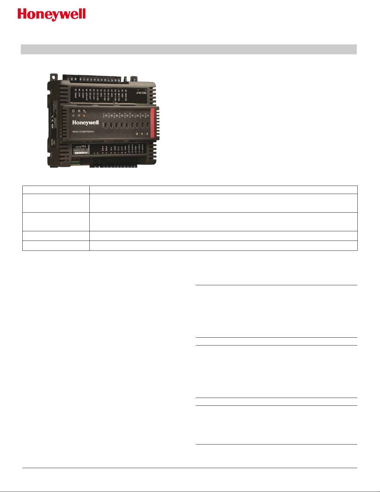
CIPer Model 30 Controller
INSTALLATION INSTRUCTIONS
Introduction
The Honeywell CIPer Model 30 is a compact, Internet
Protocol (IP) edge controller for VAV, Unitary and Plant
applications. With its native Niagara N4 on-board
programming platform; the CIPer controller provides
Internet connectivity, Web serving capability, integrated
control, data logging, alarming, trending, and scheduling
management. The controller can be used to aggregate
information (including real-time data, alarms, trends,
and history) and integrate this data to the Sentience
Cloud for value-added data analytics.
Tabl e 1 Parts and description
Model number Description
WEB-C3036EPUBNH
WEB-C3036EPVBNH
WEB-O3022H
WEB-O9056H
Honeywell CIPer - IP controller with 3 universal inputs, 6 Binary Outputs, 3 Universal I/O and
HOA switches
Honeywell CIPer - IP controller with 3 universal inputs, 6 Binary Outputs, 3 Universal I/O, VAV
airflow sensor and HOA switches
IO module with 3 universal inputs, 2 Binary Outputs, 2 Universal I/O and HOA switches
IO module with 9 universal inputs, 6 Binary Outputs, 5 Universal I/O and HOA switches
Specifications:
Power consumption: AC: Max 100VA
Rated input voltage: 20-30 VAC; 50/60Hz
Impulse voltage: 330V
Ambient temperature: -4 to 131F (-20 to 55C)
Storage temperature: -4 to 150F (-20 to 65C)
Humidity: 5% to 95% non-condensing
Differential pressure sensor range (VAV mo
WC (0 to 374 Pa) 32 to 122F (0 to 55C)
Universal Inputs / Analog Outputs (configurable)
UI
/ 3 configurable as AO
Flexible UI’s to connect external sensors like
20KNTC, PT1000 and other resistive sensors
Digital Output type / rating: Solid-State Relay, 1.5A
Continuous, 3.5A inrush for 100 mS.
Digital Output voltage rating: 20 to 30 VAC
Hz
Pulse Inputs: 100Hz max, minimum
ON / 5 mS OFF.
Purpose of Control: Operating Control,
Management Equipment
Action
Pollution degree: 2
ELV limits realized: 24V
: Type 1
duty cycle: 5 mS
del): 0-2”
@ 50/60
Open Energy
: 6
Before Installation
WARNING! Install all equipment in accordance with the
National Electric Code and in a manner acceptable to the local
authority having jurisdiction. Read these instructions and the
CIPer Model 30 controller Installation Instructions (31-00183-
01) carefully before installing equipment. Failure to follow all
instructions may result in equipment damage or a hazardous
condition.
Attention! Installez tout le matériel en conformité avec le
Code national de l'électricité et d'une manière acceptable pour
l'autorité localecompétente. Lisez ces instructions et le guide d'
installation et fonctionnement de l'ACM (LT-ACMIOG) avant
l'installation du matériel. Le non respect des instructions peut
entraîner desdes dommages matériels ou une situation
dangereuse.
WARNING! The CIPer 30 controller and its components may
be susceptible to electrostatic discharge (ESD). Use
appropriate ESD grounding techniques while handling the
product. When possible, always handle the product by its nonelectrical components.
© Honeywell Page 1 31-00183-02
Page 2
The CIPer 30 controller is available in two models (See table 1).
Review the power, input, and output specifications before installing the controller.
Installation
The CIPer Model 30 controller must be mounted in a position that allows clearance for wiring, servicing, removal,
connection of the terminal blocks and access to the MAC address DIP switches. It may be mounted in any
orientation.
Mounting
The CIPer controller mounts on a standard DIN rail in one of two ways:
vertically, with the connections on the right and left sides of the unit.
horizontally, with the connections on the top and bottom of the unit.
The controller also has a locking clip, as do both type of I/O expansion modules. Mounting on DIN rail ensures
accurate alignment of connectors between all modules. The controller can also be screw-mounted using the four
mounting tabs, accessible under the covers. These mounting tabs may be broken off if needed to save space when
DIN rail mounting.
As per the Construction of this controller, it can be mounted independently for Panel mounting.
Note: Mount the controller prior to mounting any necessary items (I/O modules).
WARNING! Be sure the CIPer controller does not have power connected while mounting.
Attention! Assurez-vous que l'appareil n'est pas connecté à l'alimentation lors du montage.
To mount the CIPer controller on a DIN rail:
1 Holding the controller with its top tilted in towards the DIN rail, hook the two top flex snaps on the back of
the controller onto the top of the DIN rail.
2 Push down and in to latch the two bottom latching tabs of the controller onto the DIN rail.
3 Properly ground the panel, then terminate grounded components of power, communications, and I/O
wiring.
To remove the CIPer controller from the DIN rail:
1 Push straight down from the top to release the bottom tabs.
2 Rotate the bottom of the controller out towards you and pull the controller up and away from the DIN rail to
release the bottom latching tabs.
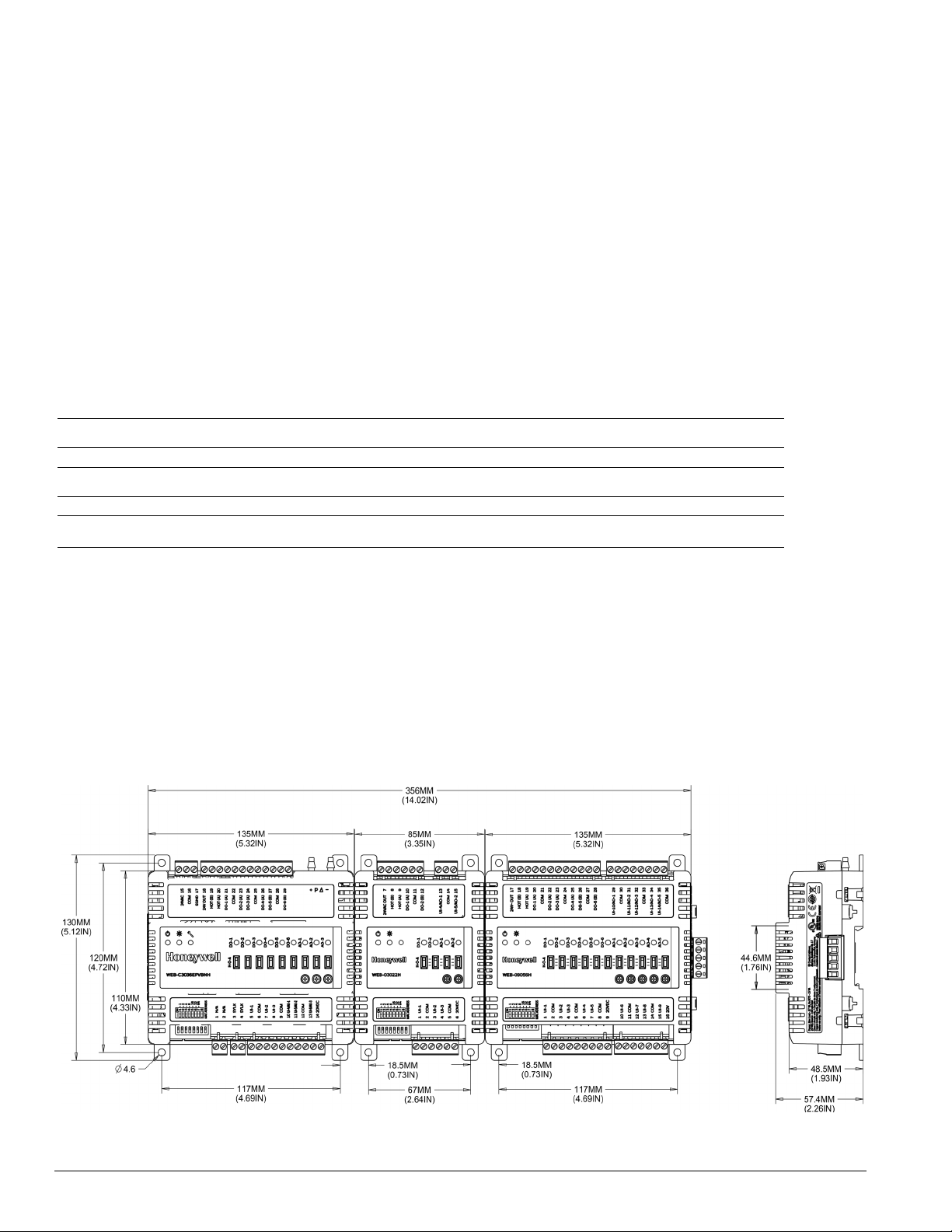
Fig. 1 Panel mounting - controller dimensions in mm (inches)
© Honeywell Printed in USA 31-00183-02
Page 3
IMPORTANT! Avoid mounting in areas where acid fumes or other deteriorating vapors can attack the metal parts of the
controller, or in areas where escaping gas or other explosive vapors are present.
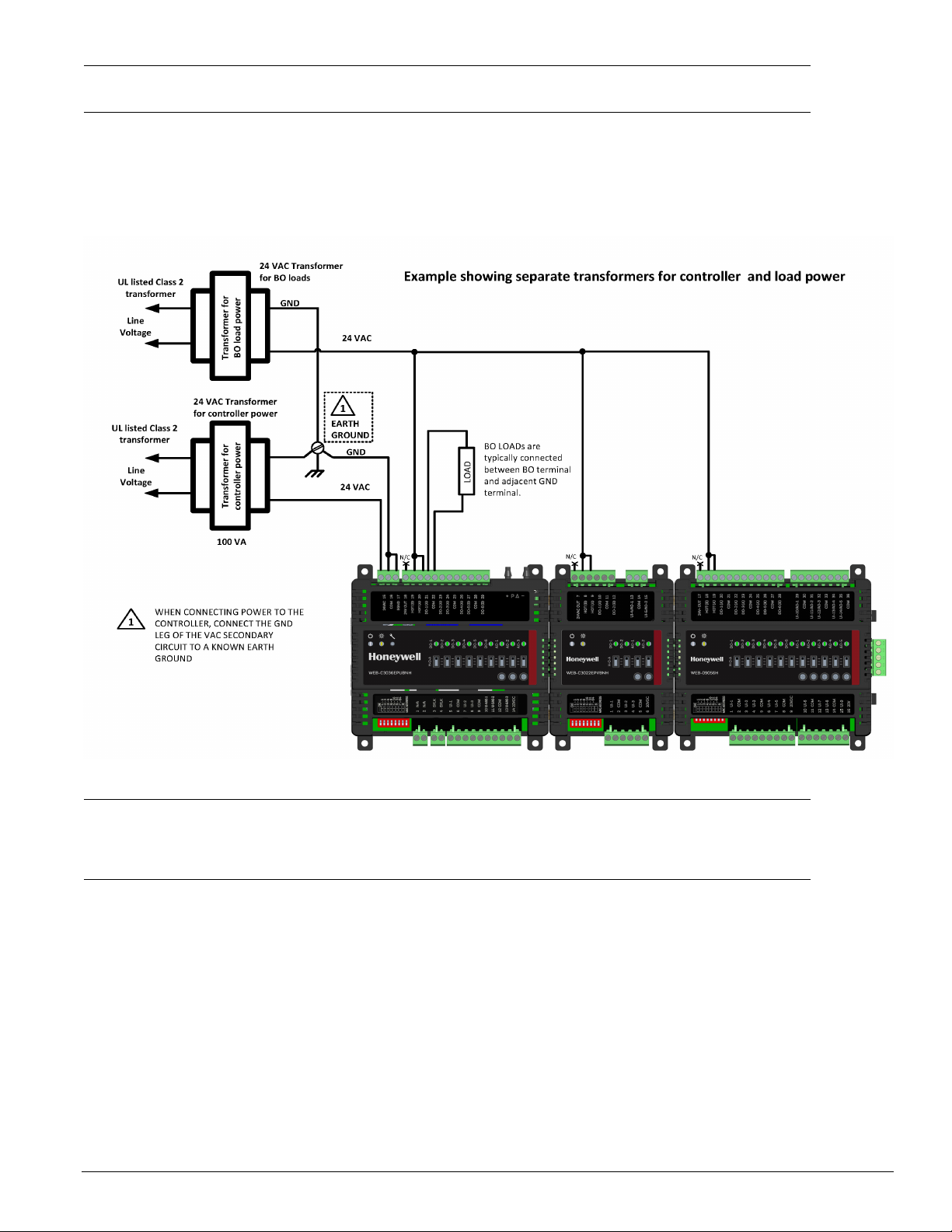
Power
The CIPer controller requires 20-30 VAC, 50/60Hz. Power consumption is based on the sum of the VA rating for
each controller and should not exceed 100VA. If additional modules are required then they must be powered from
a separate transformer. Refer VA rating for each module in the note below.
Fig. 2 Use separate transformers for controllers and load power
Note: Transformer VA load for module power only (no BO loads)
a) WEB-C3036EPVBNH = 50VA
b) WEB-O9056H = 35VA
c) WEB-O3022H = 15VA
Using Terminal blocks
The CIPer controller uses removable terminal blocks to simplify field wiring of power and cabling. If desired, you
can remove the terminal blocks from the unit, terminate cable, and reset the block when you finish.
To termina te cable:
1 Strip a wire jacket from the end of the cable.
2 Use a small screwdriver to turn the adjustment screw fully counter-clockwise. The clamps in the wire slot
separate as you turn the screw.
3 When the clamps in the wire slot are fully open, insert the stripped end of the cable (the insulation end
must be flush with the terminal block). Be sure to insert all cable strands into the wire slot.
4 Hold the cable in place and turn the adjustment screw clockwise to tighten it until the clamps in the wire
slot secure the cable. Tug gently on the cable to ensure that it’s securely terminated
© Honeywell Page 3 31-00183-02
Page 4

5 Both type of I/O modules WEB-O3022H and WEB-O9056H can be connected directly to the WEB-
C3036EPVBNH controller as shown in Fig. 3.
Fig. 3 Stacked Controller and IO modules
Fig. 4 Remotely mounted expansion module
© Honeywell Printed in USA 31-00183-02
Page 5

Table 2
Terminal Description
Terminal Descriptio
n for WEB-C3036EP controller
1,2 Not used
3, 4 2 wire SYLK bus to connect SYLK modules
5, 7, 8 Universal inputs UI-1 to 3. Software
controlled input type selection supports 10k
Thermistor (type II), Dry Contact, 0-10Vdc,
0-20mA, and Pulse (In-1, -2, -3)
6 COM terminal for UI-1 & UI-2
9 COM terminal for UI-3 & UI-4/AO-1
10, 11, 13Universal Inputs/Outputs as UI-4 to 6
Analog Outputs: selectable 0-10vDC or 0-
20mA
12 COM terminal for UI-5/AO-2 or UI-6/AO-3
14 Supplies 20V DC
15 Controller input supply voltage 24VAC
16 Supply voltage GND
17 Electrical grounding / Earth
18 24VAC output from controller's power
(terminal 15) for DO devices
19 HOT B. Supplies power to common side of
controller's DO (For DO 5,6)
20 HOT A. supplies power to common side of
controller's DO (DO 1, 2, 3, 4)
22, 25, 28GND terminal for DO-1&2, DO-3&4, DO-5&6
respectively
21, 23,
DO-1 to DO-4
24, 26
27, 29 DO-5, DO-6
Ether
net Connections
Table 3 Ethernet Connections
Ethernet
RJ-45 jack
An RJ-45 jack for connection to Ethernet is
on top of the CIPer controller. Pin
designations for the RJ-45 jack are shown.
+‒ ‒ ‒ ‒+++
Pin Assignment
1 Bi-directional pair
A+
12345678
2 Bi-directional pair
A-
3 Bi-directional pair
B+
4 Bi-directional pair
C+
5 Bi-directional pair
C-
6 Bi-directional pair
B-
7 Bi-directional pair
D+
8 Bi-directional pair
D-
Cable type
and
length
Use an approved Category 5e or better
Ethernet drop cable with RJ-45 plugs. Use
professionally manufactured cables of no
more than 328 feet (100 meters).
Disposal
The product should not be disposed of with other
household waste. Check for the nearest authorized
collection centers or authorized recyclers. The correct
disposal of end-of-life equipment will help prevent
potential negative consequences for the environment
and human health. Do not burn this device.
Conformance statement
Fig. 5 Ethernet Connections
CIPer controller has a built-in four-port 1Gig Ethernet
switch that supports 10BASE-T (10 Mbps), 100BASETX (100 Mbps), and 1000BASE-T (1000 Mbps)
Ethernet connections. It automatically operates at
1000 Mbps if other devices and cabling support it.
© Honeywell Page 5 31-00183-02
This Class B digital apparatus complies with Canadian
ICES-003.
This device complies with Industry Canada
licenseexempt RSS standard(s). Operation is subject to
the following two conditions: (1) this device may not
cause interference, and (2) this device must accept
any interference, including interference that may
cause undesired operation of the device.
Le présent appareil est conforme aux CNR d'Industrie
Canada applicables aux appareils radio exempts de
licence. L'exploitation est autorisée aux deux
conditions
suivantes: (1) l'appareil ne doit pas produire de
brouillage, et (2) l'utilisateur de l'appareil doit accepter
tout brouillage radioélectrique subi, même si le
brouillage est susceptible d'en compromettre le
Page 6

fonctionnement.
This equipment has been tested and found to comply
with the limits for a Class B digital device, pursuant to
part 15 of the FCC Rules. These limits are designed to
provide reasonable protection against harmful
interference in a residential installation. This
equipment
generates uses and can radiate radio frequency energy
and, if not installed and used in accordance with the
instructions, may cause harmful interference to radio
communications. However, there is no guarantee that
interference will not occur in a particular installation. If
this equipment does cause harmful interference to
radio
or television reception, which can be determined by
turning the equipment off and on, the user is
encouraged
to try to correct the interference by one or more of the
following measures:
Reorient or relocate the receiving antenna.
Increase the separation between the equipment
and receiver.
Connect the equipment into an outlet on a circuit
different from that to which the receiver is
connected.
Cet équipement a été testé et jugé conforme aux
limites de Classe B pour un appareil numérique, en
vertu de l’article 15 de la réglementation de la FCC. Ces
limites ont été instaurées pour fournir une protection
raisonnable contre toute interférence nuisible dans
une installation résidentielle. Cet équipement génère,
utilise et peut émettre de l’énergie radiofréquence. S’il
n’est pas installé et utilisé conformément aux
instructions, il peut provoquer des interférences sur les
communications radio. Cependant, il n’est pas garanti
que des interférences ne se produiront pas dans
certaines installations. Si cet équipement cause des
interférences à la réception radio ou télévisée (ce qui
peut être vérifié en éteignant l’appareil puis en le
remettant sous tension), l’utilisateur peut tenter de les
résoudre en suivant une ou plusieurs des mesures ciaprès:
Réorienter ou déplacer l’antenne réceptrice.
Augmenter l’espace entre l’appareil et le récepteur.
Brancher l’appareil à une prise de courant
différente de celle sur laquelle le récepteur est
branché.
Pour obtenir de l’aide, contacter le vendeur ou un
technicien radio/télévision expérimenté.
Notice
This device complies with Part 15 of the FCC rules.
Operation is subject to the following two conditions:
(1) this device may not cause harmful interference,
and
(2) this device must accept any interference received,
including interference that may cause undesired
operation.
© Honeywell Printed in USA 31-00183-02
Page 7

Honeywell Building Technologies
Honeywell International Inc.
1985 Douglas Drive North
Golden Valley, MN 55422
customer.honeywell.com
® U.S. Registered Trademark
© 2019Honeywell International Inc.
31-00183-02
 Loading...